1
®
®
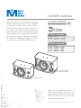
OWNER'S MANUAL
Passionate about Music
Better Music Builder is a leader in the Audio and
Karaoke equipment industry. We are committed
to offering you high quality audio products.
Unlike any others brand, we deliver the best cost
and value to you directly. We may update our
manual on short notice, so we highly recommend
downloading the latest update information including operation manuals, installation instructions,
and other new technologies updates, etc. from
our website www.BetterMusicBuilder.com.
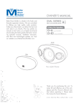
CLASSIC SERIES
PRO - Line Loudspeaker
3-Way Loudspeaker
PREMIUM GRADE
CS-600 G2
10-inch WOOFER
3-Way Loudspeaker
SUPERIOR GRADE
CS-612 G2
CS-812 G2
12-inch WOOFER
12-inch WOOFER
CS-612 G2 (PVC PLYWOOD)
CS-812 G2 (PIANO WOOD)
CS-600 G2 (PIANO WOOD)
Thank you for purchasing this unit. To
make full and effective use of this unit,
please read this Owner's Manual carefully before operating it. Please retain this
manual for future reference.
w w w. B e t t e rM usic B uil d e r.c o m
CONTENTS
INTRODUCTION............................................................................................................................................... 3
Intro
Features
SYSTEM FEATURES........................................................................................................................................... 3
SAFETY INSTRUCTIONS............................................................................................................................. 4~5
Safety
Applications
Speaker
Set Up
SYSTEM APPLICATIONS.................................................................................................................................. 6
...................................................................................................................... 6
....................................................................................................................................... 6
!"................................................. 7
#!"............................................................. 8
CONTROLS AND FUNCTIONS...................................................................................................................... 9
!$%!
&(!%)**+/0000000000000000000000000000009
!$%!
&(!%)1/+/231/+/0000009
SYSTEM SETUP GUIDELINES........................................................................................................................ 10
4
.................................................................................................................................................... 1*
10.............................................................................................1*
/0&.................................................................................................11
0!..............................................................1/
50:.................................................................................1/
%;
............................................................................................................................................ 1
<%.......................................................................................................................................................... 1
PHYSICAL DIMENSIONS....................................................................................................................... 14~15
Dimensions
SPECIFICATIONS............................................................................................................................................ 15
Spec
TROUBLESHOOTING.............................................................................................................................. 16~17
Troubleshooting
FINAL WORDS TO USER.............................................................................................................................. 17
Final Words
WARRANTY..................................................................................................................................................... 18
Warranty
AGENCY REGULATORY NOTICES.............................................................................................................. 19
Notices
CONTACT INFORMATION........................................................................................................................... 20
Contact Us
2
Intro
INTRODUCTION
Features
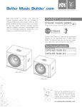
Better Music Builder is excited to introduce the next generation of the Classic Series speaker, the G2 (Generation 2). The
high performance speakers consist of three models: CS-600
G2, CS-612 G2 and CS-812 G2.
SYSTEM FEATURES
CS-600 G2 (Premium Grade)
!!"#
$%
&"#
$%
'""#
"%
*!
+$
/$
&3banana plug or insert type)
#
4'*579*5
$;<
=
>9'
/>"?*
>"
3@@
under balcony)
They are high performance speakers using dymanic audio
computer simulation design technology. Our development
enables these speakers to produce high quality sound,
precise clarity and strong reliability. They are made using high
temperature treated magnesium diaphragm, voice coil with
copper cladding aluminum wire, and compression cavity
designed with linear phase technology. Magnetic circuit of
tweeter generates high magnetic energy, low distortion,
excellent ventilation function, and high strength plywood that
can absorb unwanted noise for high performance.
The greatest improvement in terms of structure from the first
generation Classic Series is the added mid frequency
tweeter, making the second generation three-way speakers.
The midrange driver may very well be the most significant
part of the audio sound spectrum as it creates sounds which
are most familiar to the human ear such as musical instruments
and human voice.
CS-612 G2 (Superior Grade)
A/E
H!!"#
$%
4H&"#
$%
H""#
"%
*!
+$
/$
&3banana plug or insert type)
#
HJ*579*5
$;<
=
>9'
/>"?*
>"
3@@
under balcony)
Unchanged is its elegant design. The CS-600 G2 and the
CS-812 G2 speakers are designed with a black and smooth
MDF (medium density fiberboard) wood gloss layered finish.
It provides stronger foundation for both structure and sound.
The material is utilized based on the principle that softer
wood provides smoother and clearer audio output like a
grand piano.
CS-812 G2 (Superior Grade)
HIGH
HF
MID
MF
H!!"#
$%
4H&"#
$%
H""#
"%
*!
+$
/$
&3banana plug or insert type)
#
HJ*579*5
$;<
=
>9'
/>"?*
>"
3@@
under balcony)
BASS
LF HIGH
HF
MID
MF
CLASSIC SERIES
PRO - Line Loudspeaker
3
Safety
ABNORMALITY
SAFETY INSTRUCTIONS
V"!
>&"&@ or if there is a sudden loss of sound during use of the
device, or if any unusual smells or smoke should appear to
be caused by it, immediately turn off the power switch,
disconnect the electric plug from the outlet, and have the
device inspected by qualified Better Music Builder service
personnel.
V"!$!
>&@&&
turn off the power switch, disconnect the electric plug from
the outlet, and have the device inspected by qualified
Better Music Builder service personnel.
We will not notify you any errors or changes in this manual in
advance. If there are any errors and changes in this manual,
we will make the corrections in a timely manner. The
corrections and changes will be on our website. Therefore,
please visit our website at BetterMusicBuilder.com frequently to
find out the most updated information, corrections on errors
and changes in this manual. You may also contact us at toll
free at 1-800-318-2218.
LOCATION
RISK OF ELECTRIC SHOCK
DO NOT OPEN
CAUTION: TO REDUCE THE RISK OF ELECTRIC SHOCK DO NOT
REMOVE COVER (OR BACK) NO USER-SERVICEABLE PARTS
INSIDE REFER SERVICING TO QUALIFIED PERSONNEL
X
#
"<Z
<
$
personnel if the device installation requires construction
work, and make sure to observe the following precautions.
/!&
!
that can support the weight of the device.
X$!$>L
CAUTIONS FOR INSTALLATION
POWER SUPPLY / POWER CORD
?
!$""!$L The required voltage is printed on the name plate of the
device.
N!
L
P!!
! heaters or radiators, and do not excessively bend or
otherwise damage the cord, place heavy objects on it, or
place it in a position where anyone could walk on, trip
over, or roll anything over it.
&$!
"&!
!!$
not to be used for extended periods of time, or during
electrical storms.
!&$!
"&!$ outlet, always hold the plug itself and not the cord. Pulling
by the cord can damage it.
NO GOOD
DO NOT OPEN
P!$&&>!
internal parts or modify them in any way. The device
contains no user-serviceable parts. If it should appear to
be malfunctioning, discontinue use immediately and have
it inspected by qualified Better Music Builder service
personnel.
V!$L
!&$!$@
&LX&"!$>
"
may damage your back, result in other injury, or cause
damage to the device itself.
<"&$!$@&$>L
P
!$"@$
location. If this device is to be used in a small space
!![VX@&
!!
adequate space between the device and surrounding
walls or other devices: at least 30cm at the sides, 30cm
behind and 30cm above. Inadequate ventilation can
result in overheating, possibly causing damage to the
device(s), or even fire.
WATER WARNING
P!$@
damp or wet conditions, or place containers on it containing
liquids which might spill into an openings.
R$&$
!!L
4
P
!\!"
L
P
&=
L
P!$$
$>@ &!3
!
!@ !@
!]$!> ""
&!
&L
P!$
>! &!"$L
^!!$&!$
L
CONNECTIONS
IMPORTANT: P$3LL@_``_]
!&LP
&
&!>L
<"!$!$@
""! "$L<"
!"" "$@$
&$&&
&L
^
@!_&!
>"!&"$!$_3]
&!L/!`3>]&
&L!\
!
!
&"@$$"&
L
ADJUSTING
CAUTION
/!!">@">!&
$
&&&
&$@!>
&L"$&
$
&!&$
&&"
>$L
!
!X/
&@
!$+X^@$&L
!
!""@!$!
>
""V^"!&L
P
"!
!$3@L]L
X$">=3@@
&@L]!$
3@L]LV"!!@
""!&& !"&!X/
L^!
!$!$>#
"<Z
<
$L
P
!$""&!! &">$
&$@!
&!LV"
!
!@
!L
P!$"!
L
!
$!
"L
P
!!$!$
>=@$
$"!
>
@!L
NOTE
{
!
!>
!"#
&LV"@!
!
!5"&!&
!!&"&!L
^!&
">
!!&#
>"">
&>""""@
!
&\5!@!
&
>
!&@!\$!@
!"!!&L
+$"&
!>$L
V"!&
!>@&$!"&
>L/$@"
!
!@!>&>
L
CARING
[!
!"!!#
&L!@
"!&$
"
"&!
L
GETTING STARTED
WIRING
IMPORTANT: Z
#
&
"">"
&L
@
!!#
!
L^!"!!!
$L
V"@
<Z
<
!
NOTE
"L
5
Applications
SYSTEM APPLICATIONS
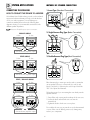
METHODS OF SPEAKER CONNECTION
CONNECTING THE SPEAKERS
1. Insert Type (Standard Connection)
HOW TO CONNECT THE SPEAKER TO AMPLIFIER
We at Better Music Builder always provide you the technical
support and relevant information to help you make the best
use of your audio equipment. To avoid damages in
connection mistakes please refer to the following three
diagrams showing our recommended connections for the
different speaker impedance.
NOTE
GOOD
NO GOOD
Please turn off amplifier power prior to connection.
2. Single Banana Plug Type (Better Connection)
PARALLEL WIRING
4 ohm
4 ohm
4 ohm transformer (amplifier output)
3. Double Banana Plug Type (Best Connection)
SERIES WIRING
8 ohm
8 ohm
3/4”
19 mm
8 ohm transformer (amplifier output)
SERIES / PARALLEL WIRING
8 ohm
8 ohm
8 ohm
Either banana plug or insert type can be used to connect the
unit to speakers. Be sure to connect red (+) to red (+) and
black (–) to black (–). Otherwise, the sound output would be
180° out of phase and distorted.
Follow these steps if you are inserting the wire directly into the
speaker terminal.
8 ohm
1. Strip off the vinyl covering and twist the tip of the wire core.
2. Loosen the knob and insert the wire core into the
terminal hole.
3. Tighten the knob to fix the wire core in place.
Do not allow the wire core to protrude or touch other terminals
or wires. If the cores of differing wires touch, damage may
result to your components.
8 ohm transformer (amplifier output)
6
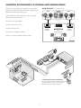
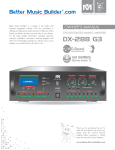
CONNECTING THE SPEAKER WITH 3-D POSITIONAL AUDIO (PREMIUM FORMAT)
Please refer to the diagram on the right for connecting the
speakers to the 3-D Positional Audio system designed by the
Better Music Builder engineering team.
Model: DX-222 G2 3-D Positional Audio
With 3-D Positional Audio technology, user can actually
experience the following effects:
MAIN
CENTER
VOCAL
MAIN
RIGHT
SUBWOOFER
LEFT
<Q
0
Q0
CENTER MONITOR
MAIN LEFT
SPEAKER
CS-600 G2
(0
MAIN LEFT
SPEAKER
CS-600 G2
HD TV
%Q
0
Small Room 300 sq ft
:
:
0
M
2
0 G FS - 3
D
- 60
CS ITOR
R
N
KE
O
A
E
M
SP
/
ER
HT
R I G C EN T
N
I
A
06
MA
IN
RI G
HT
S PE
D
VO
Y
PL A
ER
DP
DV
E
L AY
R
od
/iP
ne
o
i P h o r Y ER
A
PL
D
O
K
REA
R
MIC
INP
UT
MIC
VO
D
4
MP3
or
Comp
iPhon
atible
REM
e
OTE
VID
MIC
EO
5
INP
KOD
PowCen
er ter
Sel Out
ect put
or
ter
UT
TER
KOD
SENS
DVD
MIN
DVD
SAIS
Prio
rit
AL
ITIVIT
Cen
VID
EO
OUT
VOD
Y
SUB
LINE
OUT
KOD
SUBW
Sub
wo
CEN
OOFER LINE TER
y
ofe
r
VOCOUT
MON AL
ITOR
VOD
MA
RECO
IN
RD
AUX
AUD
IO
PRE-
INP
UT
AMP
SAIS
Prio
rit
RIG
TER
MIN y
AL
L
CEN
VO TER
CA
L
HT
AUD
IO
OUT
PUT
R
SU
BW
MA
OO
IN
FER
SP
EA
CAT
4-16ION
:SYS
Ohm
KE
LEF
RS
T
OU
TEM
/SP
AKEIMP
R EDA
®
3-CH
TP
Bett
UT
NCE
ANN er
CALIF
Mus
EORNIEL
mail:
ic
w
Build
A, MOD
w
w inf UNITE EL:
. B o@b
er®
ENGIN
et
D
DXt e e t t STATE
EERE
r M erm
22
D
u s u si S OF
AND
2
i c c bui AMER
3
Bu
G2
6
DESIG
i l ld e ICA
1
0
N d e r r.c o
IN . c m
9
U.S.Ao
L NO.:
0
m
9
.
0
SERIA
Fan
when
turns
1
-
0
WA
RISK
RN
OF
ELEC
DO
ING
NOTTRIC
OPEN
SHO
1
CPU the on
auto
FrequINTEG temp
mati
Powe ency RATE eratu
cally
AC r
re
Range D
Consu
Powe
MIXIN reac
: 20Hz
mptio
r Input
hes
G
AMP
n:
~ 20KH
Volta
300W
LIFIE
ge:
z
R
AC~12
CK
0V~2
40V
AK
ER
+
CS
CD
- 60
dio
Au
nal VI E W
o
i
t
R
i
Pos REA
3- D 2 G2
2
2
DX
G
0G
2
VI D
EO
MO
NIT
OR
PC
STE
- SY
M
N
CO
T RO
PC MANAGED EFFECT CONTROL SOFTWARE SUITE
L
Passionate about Music
®
®
Better Music Builder
w w w. B e t t e r M u s i c B u i l d e r.c o m
G2 Series is great for home live concert and KTV business
DX-222 G2 3-D Positional Audio is great for 300sq ft
DX-288 G2 5-D Pro Audio is great for 800sq ft
7
Effect Control
Sof tware Suite
Pro-Audio
CPU Amplifier
G2 SERIES
Generation 2
©
20
10
B et
ter
Mus
. <e
ic B ui
l d er. All rights re se r Qed
g al
t ra
de
ma
rk .
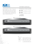
CONNECTING THE SPEAKER WITH 5-D PRO AUDIO (SUPERIOR FORMAT)
Please refer to the diagram
on the right for connecting
the speakers to the 5-D Pro
Audio system designed by
the Better Music Builder
engineering team.
The concept of 5-D Pro
Audio technology is the
same as that of the 3-D
Positional Audio technology.
The 5-D Pro Audio
technology factors in the
echo and reverb generated
by the size and shape of the
room as well as the materials
used in the construction of
the room into the Digital
Signal Processing equation.
The control feedback can
easily be done from the front
panel as with the adjustment
of vocal and music effects
between the center and main
speakers.
Model: DX-288 G2 5-D PRO Audio
GROUP-A
GROUP-A
CENTER
VOCAL
GROUP-B
GROUP-B
LEFT
RIGHT
SUBWOOFER
LEFT
RIGHT
OR
CENTER MONITOR
MAIN LEFT SPEAKER
CS-612 G2/CS-812 G2
MAIN RIGHT SPEAKER
CS-612 G2/CS-812 G2
ACTIVE SPEAKER
PS-310A
HD TV
Large Room 800 sq ft
MAIN RIGHT SPEAKER
CS-612 G2/CS-812 G2
MAIN RIGHT SPEAKER
CS-612 G2/CS-812 G2
G2 306
12
S - 8 R DFS
C
A
MA
ER
TO
310
I
K
IN
S
A
N
P
RI G
S PE / M O
K ER
HT
T
A
H
R
S PE
PE
G
E
I
S
T
R
E
N
AK
N
V
E
I
I
T
C
ER
A
M
AC
CS
- 81
2G
2
D
VO
Y
PL A
ER
DP
DV
E
L AY
R
od
/iP
ne
o
i P h o r Y ER
A
PL
D
O
K
REA
R
MIC
INP
UT
MIC
VO
4
MP3
D
or
Comp
iPhon
atible
REM
e
OTE
VID
MIC
EO
5
INP
KOD
PowCen
er ter
Sel Out
ect put
or
ter
UT
TER
KOD
SENS
DVD
MIN
DVD
SAIS
Prio
rit
AL
ITIVIT
Cen
VID
EO
OUT
VOD
Y
SUB
LINE
OUT
KOD
SUBW
GR
Sub
wo
CEN
OOFER LINE TER
y
OU
P-A
ofe
r
VOCOUT
MON AL
ITOR
VOD
GR
RECO
LEF
RD
OU
T
P-A
AUX
AUD
IO
PRE-
INP
UT
AMP
SAIS
Prio
rit
RIG
TER
MIN y
AL
L
CEN
VO TER
CA
L
HT
AUD
IO
OUT
PUT
SU
R
GR
BW
OO
SP
P-B
GR
EA
CAT
4-16ION
:SYS
Ohm
KE
LEF
RS
OU
T
OU
TEM
/SP
AKEIMP
R EDA
®
5-CH
TP
Bett
UT
NCE
ANN er
CALIF
Mus
EORNIEL
mail:
ic
w
Build
A, MOD
w
w inf UNITE
. B o@b
EL:
er®
ENGIN
et
D
DXt e e t t STATE
EERE
r M er musi
S OF288
D
us
AND
i c c builAMER
3
Bu
G2
6
DESIG
i l de ICA
1
0
N d e r r.c o
IN . c m
9
U.S.Ao
L NO.:
0
m
9
.
0
P-B
RIG
HT
SERIA
1
Fan
when
turns
the on
-
0
WA
RISK
RN
OF
ELEC
DO
ING
NOTTRIC
OPEN
SHO
9
CPU
FrequINTEG temp
mati
Powe ency RATE eratu
cally
AC r
re
Range D
Consu
Powe
MIXIN reac
: 20Hz
mptio
r Input
hes
G
AMP
n:
~ 20KH
Volta
300W
LIFIE
ge:
z
R
AC~12
auto
CK
0V~2
40V
+
CD
VI D
EO
MO
G
DX
NIT
OR
PC
RE A
R
H
RI G
TS
PE A
K ER
DFS
RL
EF
PE
TS
AK
ER
6
-20
DFS
STE
- SY
M
dio
Au I E W
RO A R V
P
5 - D 2 RE
8G
-28
N
CO
T RO
L
6
-20
Passionate about Music
®
®
Better Music Builder
w w w. B e t t e r M u s i c B u i l d e r.c o m
Effect Control
Sof tware Suite
Pro-Audio
CPU Amplifier
G2 SERIES
Generation 2
©
RE A
OU
FER
20
10
B
et te
r
Mus
. Le
ic B ui
l d er. All rights re se r ved
g al
t ra
de
ma
rk .
PC MANAGED EFFECT CONTROL SOFTWARE SUITE
G2 Series is great for home live concert and KTV business
DX-222 G2 3-D Positional Audio is great for 300sq ft
DX-288 G2 5-D Pro Audio is great for 800sq ft
8
CONTROLS AND FUNCTIONS
FRONT & REAR PANEL: features are available for 3-WAY FULL RANGE SPEAKER model CS-600 G2
Front View
Top View
Rear View
2
3
1
6
4
CS-600 G2
Speaker
5
1
3-INCH TWEETER: PAPER CONE HIGH FREQUENCY DRIVER
2
MOUNTABLE SCREW: TWO 8mm SCREW SIZE
3
10-INCH WOOFER: PAPER CONE LOW FREQUENCY DRIVER
4
3-INCH TWEETER: PAPER CONE MIDDLE FREQUENCY DRIVER
5
FRONT GRILL COVER
6
SPEAKER INPUT TERMINAL
Front View
Top View
Rear View
3
1
4
8
5
2
6
7
1
3-INCH TWEETER: PAPER CONE HIGH FREQUENCY DRIVER
2
4-INCH TWEETER: PAPER CONE MID FREQUENCY DRIVER
3
MOUNTABLE SCREW: TWO 8mm SCREW SIZE
4
3-INCH TWEETER: PAPER CONE HIGH FREQUENCY DRIVER
5
12-INCH WOOFER: PAPER CONE LOW FREQUENCY DRIVER
6
4-INCH TWEETER: PAPER CONE MID FREQUENCY DRIVER
7
FRONT GRILL COVER
8
SPEAKER INPUT TERMINAL
9
5
CS-612 G2/CS-812 G2
FRONT & REAR PANEL: features are available for 3-WAY FULL RANGE SPEAKER model CS-612 G2/CS-812 G2
Set Up
SYSTEM SETUP GUIDELINES
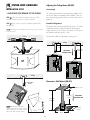
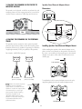
Adjusting the Ceiling Mount (NB-901)
INSTALLATION SETUP
Precise Angle
1. MOUNTING THE SPEAKER TO THE CEILING
The Ceiling Mount allows swing adjustment, slightly loosen
an screw to make an adjustment, then re-tighten. Once you
have set up the right position, then you can use the screw to
tight it up.
STEP 1 : Place the wall mount panel on the top of the
speaker cabinet and use two screws to fasten it.
Extended Ceiling Mount
STEP 2 : Then, use four screws to hold the speaker firmly
into the wall.
The length of the arm for the wall/ceiling mount is 7.5 inches
without any extension. With full extension, the maximum
length of the arm is 12.5 inches. Since there are 5 drops on
the extension and each drop is 1 inch.
The structure of the ceiling must be strong enough to hold at
least 50 pounds.
NOTE
Ceiling
Part Number: NB-901 (Optional) for ceiling mount.
2
Ceiling
7.5 inches
19 cm
1
ADJUSTABLE
EXTENSION TUBE
12.5 inches
31.8 cm
Ceiling
Dimensions: Wall Mount (NB-901)
ADJUSTABLE
ANGLE
4.3 inches
11 cm
4.3 inches / 11 cm
-6 d
80
We recommend that the
speakers be tiled at an angle, so that it
aims at audience’s ear level in order to
achieve the best accoustic quality.
Deg
7.5 inches
19 cm
B
9.3 inches
23.5 cm
re e
ADJUSTABLE
EXTENSION TUBE
NOTE
4.5 inch
11.5 cm
-6 dB
7.1 inch
18 cm
20 Feet
10
2. MOUNTING THE SPEAKER TO THE WALL
Adjusting the Wall Mount (NB-901)
STEP 1 : Place the wall mount panel on the top of the
speaker cabinet and use two screws to fasten it.
Precise Angle
The Wall Mount allows swing adjustment, slightly loosen an
screw to make an adjustment, then re-tighten. Once you
have set up the right position, then you can use the screw to
tight it up.
STEP 2 : Then, use four screws to hold the speaker firmly
into the wall.
NOTE
The structure of the ceiling must be strong enough to hold at
least 50 pounds.
Extended Wall Mount
The length of the arm for the wall/ceiling mount is 7.5 inches
without any extension. With full extension, the maximum
length of the arm is 12.5 inches. Since there are 5 drops on
the extension and each drop is 1 inch.
Wall
2
1
Part Number: NB-901 (Optional) for wall mount.
ADJUSTABLE
ANGLE
Wall
Mounting to Solid Wood or Wood Studs
In North America, most of the houses have 2”x4” wood studs
inside the panel walls. You may use stud finder to locate the
wood studs. Then, you can drive the screw into the wood
stud to mount the speaker bracket and hold it firmly.
PANEL WALL
2”X4” WOOD STUD
ADJUSTABLE
EXTENSION TUBE
12.5 Inches
31.8 cm
2”X4” WOOD STUD
Wall
PANEL WALL
11
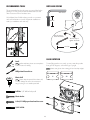
3. PLACING THE SPEAKER ON THE FLOOR TO
MONITOR SINGING
Speaker Stand External Adapter Mount
Dimensions:
This speaker can be placed on the floor to perform the vocal
monitoring function for live singing experience. It can also be
used for business conference, coffee shop and church, etc.
2 inches
5.2 cm
7.1 inches
18 cm
4.75 inches
12 cm
0.5 inches
1.3 cm
Floor
4. PLACING THE SPEAKERS ON THE PORTABLE
STAND
The speakers can be mounted on to the optional portable
stand (see figure below). Make sure that the mounting system
(hardware, stand, etc.) is capable of supporting four times the
weight (approximately 25 lbs per speaker) of the speakers.
Installing Speaker Stand External Adapter Mount
When installing the speaker to the external adapter mount,
please use the screws already on the speaker. If the head of
the screw is too small for the rectangular gap on the external
adapter mount, place a flat washer in between the screw
and the gap.
Part Number: AMS001B (Optional).
SCREW
FLAT WASHER
LEFT SPEAKER
(Stand is not included)
RIGHT SPEAKER
(Stand is not included)
Please do not stack two-pieces
of speakers onto the adjustable
speaker stand. If you need two more
speakers to increase the output volume,
we recommend you to use a high
power speaker instead of stacking
two-pieces of speaker on the
adjustable speaker stand for safety
purpose. You may also contact us at
www.bettermusicbuilder.com for
professional advice.
To stabilize the hold on external adapter mount to the pole,
apply the tightening knob to the external adapter mount.
NOTE
CAUTION
TIGHTENING KNOB
12
RECOMMENDED TOOLS
NUTS AND SCREWS
The recommended tools in this page are not included in the
package. You may purchase the recommended tools and
other accessories from a hardware store.
Allen Screw
We at Better Music Builder always provide our customers
with useful information on audio equipment installation to
make your installation safe and easy.
8 mm
30 mm
Turn this way to
loosen the screw.
Turn this way to
tighten the screw.
4 inches
LOGO ROTATION
Pencil
To install the speaker on a stand, you may rotate the speaker
front grill 180 degrees, so that the logo is upright.
Before installation, please use a template to
mark the location for drilling.
NOTE
NOTE
Phillips Head Screw Driver
DRILL
Electric Drill
NOTE
Please adjust the speed of the electric drill,
or it may damage the screw. We recommend
using a screw gun or a variable speed drill.
Drill Bits: 1/8” drill bit for drywall
Plastic Anchor
8-32x1/2” Phillips pan head machine screw
3/32” Drill Bit
13
Please wear gloves when rotating grill as it has sharp edges!
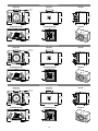
CS-600 G2 (10-inch Woofer)
FRONT VIEW
4 inch/10 cm
11.4 inch
29 cm
REAR VIEW
4 inch/10 cm
12.4 inch
31.5 cm
19.7 inch/50 cm
SIDE VIEW
12.4 inch
31.5 cm
19.7 inch/50 cm
SEE-THROUGH TOP VIEW
12.4 inch
31.5 cm
11.4 inch/29 cm
SEE-THROUGH SIDE VIEW
PERSPECTIVE
11.4 inch
29 cm
19.7 inch/50 cm
CS-612 G2 (12-inch Woofer)
FRONT VIEW
4 inch/10 cm
13.6 inch
34.5 cm
REAR VIEW
4 inch/10 cm
13.8 inch
35 cm
24.1 inch/61.2 cm
SIDE VIEW
13.8 inch
35 cm
24.1 inch/61.2 cm
SEE-THROUGH TOP VIEW
13.8 inch
35 cm
13.6 inch/34.5 cm
SEE-THROUGH SIDE VIEW
PERSPECTIVE
13.6 inch
34.5 cm
24.1 inch/61.2 cm
CS-812 G2 (12-inch Woofer)
FRONT VIEW
4 inch/10 cm
13.6 inch
34.5 cm
REAR VIEW
4 inch/10 cm
13.8 inch
35 cm
24.1 inch/61.2 cm
13.8 inch
35 cm
24.1 inch/61.2 cm
SEE-THROUGH TOP VIEW
SIDE VIEW
SEE-THROUGH SIDE VIEW
13.6 inch
34.5 cm
24.1 inch/61.2 cm
14
13.8 inch
35 cm
13.6 inch/34.5 cm
PERSPECTIVE
Dimensions
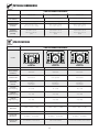
PHYSICAL DIMENSIONS
3-WAY FULL RANGE LOUDSPEAKER
MODEL
CS-600 G2
CS-612 G2
CS-812 G2
NET WEIGHT
23.8 lbs / 10.8 kg (each)
36 lbs / 16.3 kg (each)
38 lbs / 17.2 kg (each)
SHIPPING WEIGHT
54 lbs / 24.5 kg (pair)
40.6 lbs / 18.4 kg (each)
42.6 lbs / 19.3 kg (each)
DIMENSIONS
(WXHXD)
19.7 x 12.4 x 11.4 in
50 x 31.5 x 29 cm (each)
24.1 x 13.8 x 13.6 in
61.2 x 35 x 34.5 cm
24.1 x 13.8 x 13.6 in
61.2 x 35 x 34.5 cm
PACKING
DIMENSIONS
(WXHXD)
27 x 24 x 15.7 in
68.5 x 61 x 40 cm
(pair)
17.9 x 27.4 x 16.1 in
45.5 x 69.5 x 41 cm
(each)
17.9 x 27.4 x 16.1 in
45.5 x 69.5 x 41 cm
(each)
Spec
SPECIFICATIONS
3-WAY FULL RANGE LOUDSPEAKER
MODEL
CS-600 G2
CS-612 G2
CS-812 G2
TYPE
Front
Front
Front
MAX. POWER
HANDLING
450 Watts
600 Watts
600 Watts
CABINET TYPE
Piano Wood
PVC, Plywood
Piano Wood
SUPPORTED
FIXTURE
Ceiling,
Wall Mount,
Floor Stand
Ceiling,
Wall Mount,
Floor Stand
Ceiling,
Wall Mount,
Floor Stand
WOOFER
[Low Frequency]
10” (1 unit)
12” (1 unit)
12” (1 unit)
TWEETER
[Middle Frequency]
3” (1 units)
4” (2 units)
4” (2 units)
TWEETER
[High Frequency]
3” (1 units)
3” (2 units)
3” (2 units)
RATED IMPEDANCE
8 ohms
8 ohms
8 ohms
FREQUENCY
RESPONSE
40Hz ~ 18kHz ( ± 3 dB)
25Hz ~ 18kHz ( ± 3 dB)
25Hz ~ 18kHz ( ± 3 dB)
SENSITIVITY
91 dB/1W/1M
93 dB/1W/1M
93 dB/1W/1M
CROSSOVER
FREQUENCY
HIGHLIGHTED
FEATURES
LF: 300Hz
HF: 6.3kHz
3-Ch Karaoke / Piano Wood
LF: 300Hz
HF: 6.3kHz
3-Ch & 5-Ch Karaoke
15
LF: 300Hz
HF: 6.3kHz
3-Ch & 5-Ch Karaoke / Piano Wood
Troubleshooting
TROUBLESHOOTING
1. SYMPTOM: NO SOUNDS COMING OUT FROM THE
SPEAKERS
3. SYMPTOM: NOISES FROM THE SPEAKER.
Probable cause:
Probable causes:
The A/C power cord of the speaker is not grounded.
1. The A/C power of the speaker is not turned on.
Remedy:
2. Chose the wrong A/C power selection (i.e. 110V~
220V).
Change a new magnet cord of the A/C power cord.
Remedy:
4. SYMPTOM: MICROPHONE VOLUME IS TOO LOW.
A. Turn on the A/C power of the speaker.
Probable causes:
B. Check the receiver or amplifier if it is on and the source is
playing.
A. The microphone is poorly connected to the speaker.
B. The volume on the speaker is too low.
C. Check all wires and connections between receivers,
amplifiers and speakers. Make sure all wires are connected.
None of the speaker wires are frayed, cut or punctured, and
no wires are touching each other.
Remedy:
A. Check the connection between the microphone and the
speaker. Make sure that they are connected properly.
Condense microphone doesn't work with the speaker. You
may need to change to a dynamic vocal microphone.
D. Review proper operation of your receiver or amplifier.
E. Choose the right A/C power.
B. Turn the volume to an appropriate level. If the volume is
still not high enough, you may need to upgrade your existing
audio system to a system with much higher output.
2. SYMPTOM: NO SOUNDS COMING OUT FROM ONLY
ONE SPEAKER
Probable cause:
5. SYMPTOM: CRACKING NOISES FROM THE SPEAKER.
The A/C power of the speaker is not turned on.
Probable cause:
Remedy:
The tweeter may be burned out.
A. Check the "Balance" control on your receiver or amplifier.
Remedy:
B. Check all wires and connections between receiver,
amplifier and speaker. Make sure all wires are connected.
Make sure none of the speaker wires are frayed, cut or
punctured, and that no wires are touching each other.
Replace with a new tweeter.
Note: we recommend hiring a professional to change a
tweeter in order to do it properly.
C. In Dolby® Digital or DTS ® mode, make sure that the
receiver or processor is configured so that the speaker in
question is enabled.
6. SYMPTOM: SOUNDS LIKE DAZZ, DAZZ, DAZZ ........
COMING FROM THE SPEAKER.
D. Turn off all electronics and switch the speaker in question
with another speaker that is working correctly. Turn
everything back on, and determine whether the problem is in
the same place: i.e., the speaker that was working previously
now has no sound and the speaker that was not working
now sounds fine. If the problem is in the same place, the
source of the problem is most likely with your receiver or
amplifier, and you should consult the owner's manual for
further information. If the problem is with the speaker, consult
your dealer for further assistance, or visit our web site for
technical support.
Probable cause:
The speakon cable (with small gauges) is over 100 feet for
connection.
Remedy:
Change to a cable with 12 or 14 gauges or a high quality
cable with bigger size.
16
Final Words
7. SYMPTOM: TOO MUCH MICROPHONE FEEDBACK
FROM THE SPEAKER.
FINAL WORDS TO USER
The engineering team of Better Music Builder has many
years of experience in audio equipment design. The team
constantly develops new audio technologies, designs
innovative audio and karaoke equipment to suit your specific
needs and provides you great ideas for home entertainment.
Probable cause:
Incorrect tremble and bass adjustments on the speaker.
Remedy:
Our engineering team also designs audio equipments for
commercial use by restaurants, coffee shops, churches, and
school auditoriums, etc. If the commercial area for audio
equipment installation exceeds 2,000 square feet, we highly
recommend hiring audio professionals to handle the
installation to avoid damaging the equipment with improper
installation and safety protection purposes.
Adjust the tremble and bass to an appropriate level to avoid
microphone feedback.
8. SYMPTOM: NO SOUND FROM THE MAIN SPEAKERS
Probable cause:
Speakon connectors are not connected properly.
We also provide educational and technical information on
audio equipments and technologies. For example, we
provide free installation diagrams to make it easier to
connect the system. In addition, to get best connections for
the sharpest image and sound quality, we provide hot tip for
choosing high quality A/V cables. Free information on audio
equipments and technologies is available for download on
our website, w w w.B et terM usicB uil d er.com.
Remedy:
Please make sure that the speakon connectors are locked
tight. Please also note that there are two groups of speakon
connectors (i.e. Group 1 +1, –1, Group 2 +2, –2). Make
sure that your speakers have the multifunction that enables the
connection to Group 2 for different signal inputs. The basic
connection is on Group 1 (+1, –1).
Please do not remove the “Yellow Label”
in the rear of the machine; otherwise, the
warranty will be void automatically. We
design it to protect your own safety. If
repair and maintenance service is needed,
Any form of
tampering with this
please contact us directly or hire a
product, will void
the warranty.
professional technician. To learn more
about the technical aspects, visit our website
w w w.B et terM usic B uil d er.com and download relevant
information for review.
9. SYMPTOM: SOMETIMES THE SPEAKERS HAVE NO
SOUND.
Probable cause:
When the master volume reaches the maximum level, the
speaker automatically shuts down because this speaker has
a built-in auto circuit to protect itself when the master volume
becomes too high.
Remedy:
Before hooking up the system, turn off the AC powers on all
machines including audio/video equipment and TV.
Otherwise, it may damage the equipment, especially on the
HDTV in which a spot might appeared on the TV screen.
After hooking up the system, double check the audio/video
connections to ensure that they are connected correctly.
Change to a higher power amplifier to work with the
speakers. Please make sure the output power of the amplifier
can match that of the speakers. Another option is to add
more speakers or subwoofers for higher output as below.
1. Add one more loudspeaker.
2. Add one more powered subwoofer.
NOTE
Sometimes, loose or poor cable quality would affect
the microphone effects, picture quality, or even cause the
machine to shut down suddenly.
We highly recommend hiring an audio professional for
advise on the right engineering for the amplifier and
speakers.
Again, we must thank you for choosing a Better Music
Builder product. We hope you can make the best use of the
machine and enjoy it for years to come. If you have any
questions regarding our product, please feel free to contact
us at w w w.B et terM usicB uil d er.com.
17
Warranty
WARRANTY
ONE-YEAR LIMITED WARRANTY FOR HOME USE
EQUIPMENT
ADDITIONAL NOTES:
1. Limited warranty for home use equipment is only valid in
North America.
Our one-year warranty covers both parts and labors. The
warranty becomes effective from the date of your purchase
for one year.
2. Limited warranty is valid only if you purchase our products
from our authorized dealers (including both regular retailers
and online retailers) in North America. If you choose to
purchase our products from an authorized dealer, we will not
provide any limited product warranty for you. To protect your
limited product warranty, please purchase our products from
one of our authorized dealers in North America near you.
Our warranty only covers defects due to product
defectiveness with free of defects in materials or
workmanship. However, our warranty does not cover defects
due to normal wears, damage in transit, improper use, abuse
or failure to follow the proper instructions for maintenance.
This warranty is void in the event of unauthorized repairs,
alternations, modifications and removing of the product label.
3. Limited warranty is automatically void if the yellow label
stating “No Warranty After Opening” is removed from the
product.
Please also note that our warranty does not cover any
shipping cost for the return of defective products to us for
inspection, repair and maintenance. Our warranty for Better
Music Builder products can only be executed in North
America.
TO REGISTER YOUR WARRANTY
Please fill out the warranty card that came with your unit,
download or submit online warranty form. However, we need
the invoice for your purchase in order to process this warranty.
You may also register your warranty online.
Please visit our website at w w w.b et termusicbuilder.com.
90-DAY LIMITED WARRANTY FOR PUBLIC AND
COMMERCIAL USE EQUIPMENT
Our 90-day warranty applies to speakers, amplifiers, mixers
and microphones for both public and commercial use such as
restaurant, coffee shop, KTV nightclub, church and school,
etc. It covers both parts and labors. The warranty becomes
effective from the date of your purchase for 90 days.
Our warranty only covers defects due to product
defectiveness with free of defects in materials or
workmanship. However, our warranty does not cover defects
due to normal wears, damage in transit, improper use, abuse
or failure to follow the proper instructions for maintenance.
This warranty is void in the event of unauthorized repairs,
alternations, modifications and removing of the product label.
Please also note that our warranty does not cover any
shipping cost for the return of defective products to us for
inspection, repair and maintenance. Our warranty for Better
Music Builder products can only be executed in North
America.
18
Notices
AGENCY REGULATORY NOTICES
Federal Communications Commission Notice
your waste equipment at the time of disposal will help to
conserve natural resources and ensure that it is recycled in a
manner that protects human health and the environment. For
more information about where you can drop off your waste
equipment for recycling, please contact your local city office,
your household waste disposal service or the shop where you
purchased the product.
These limits are designed to provide reasonable protection
against harmful interference in a residential installation. This
equipment generates, uses, and can radiate radio frequency
energy and, if not installed and used in accordance with the
instructions, may cause harmful interference to radio
communications. However, there is no guarantee that
interference will not occur in a particular installation. If this
equipment does cause harmful interference to radio or
television reception, which can be determined by turning the
equipment off and on, the user is encouraged to try to correct
the interference by one or more of the following measures:
%Q0
4
:
receiver.
from that to which the receiver is connected.
Q
technician for help.
Japanese Notice
Japanese Power Cord Notice
Modifications
;!
:(
modifications made to this device that are not approved may
void the user’s authority to operate the equipment.
Japanese Material Content Declaration
Cables
Q
:
:
%!424
!
0
A Japanese regulatory requirement, defined by Specification
4*#*/**#
Q
(1/**)0
Materials Disposal
Korean Notice
Disposal of this material can be regulated because of
environmental considerations. For disposal or recycling
(
4
4"2200"0
Recycling Program
Disposal Of Waste Equipment By Users In
Private Households In The European Union
The terms and availability of these programs vary by
geography because of differences in regulatory requirements
and local customer demand.
This symbol on the product or on its packaging indicates that
this product must not be disposed of with your other
household waste. Instead, it is your responsibility to dispose of
your waste equipment by handing it over to a designated
collection point for the recycling of waste electrical and
electronic equipment. The separate collection and recycling of
ഖѰ൞ᖉ൦Ⲻⴇ㇗㾷≸ૂᇘᡭⲺ䴶≸θ䘏ӑᶗԬૂぁᓅⲺ
߫уੂȾ
19
Contact Us
CONTACT INFORMATION
MAILING ADDRESS
B E T TER M USI C BU I L D ER
2930 0 Kohoutek Way #150
Union Cit y, CA 94587
U.S.A.
TELEPHONE NUMBERS
USA Region
USA Toll Fre e: 1-80 0 -318-2218
S ale s & M arketing: 510 - 477-9 955
Customer S er vice: 510 - 477-9955
FAX NUMBERS
USA Region
S ale s & M arketing: 510 - 477-9 922
Customer S er vice: 510 - 477-9922
WORLD WIDE WEB
E-mail: [email protected]
Website: www.bettermusicbuilder.com
MAINTENANCE
With proper maintenance and regular service, it would maintain the machine quality and prolong its life. We recommend you to
print the following information clearly for future reference on maintenance and warranty.
MODEL#_________________________________ DATE PURCHASED (MM/DD/YYYY)_____________________________
DEALER NAME_______________________________ CITY_____________ ST./PROV._______ ZIP/P.C._______________
DEALER WEBSITE http://www.______________________________________________ INVOICE #__________________
DEALER PHONE #_____________________________ DEALER E-MAIL_________________________________________
20
21
22
23
®
®
Unlike any others ... that’s cost & value for you
Passionate about Music
w w w. B e t t e rM us i c B u i l d e r.c o m
Thank you for purchasing this unit. To make full
and effective use of this unit, please read this
Owner's Manual carefully before operating it.
Please retain this manual for future reference.
361110615000
Printed on 100% Recycled Paper
Code: 20110810
Comments E-mail to [email protected]
Copyright © 2011 Better Music Builder. All rights reserved. Legal trademark.