1
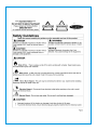
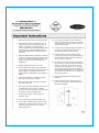
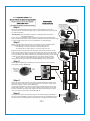
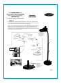
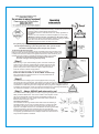
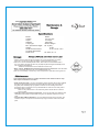
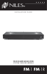
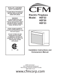
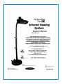
60253
This appliance MUST be grounded.
* When using outdoors, we recommend using a certified GFI (Ground
Fault Interrupt) outlet to protect against electrical shock.
* All installation must be in accordance with I.E.E. safety regulations or
equivalent.
* Do not place any objects such as furniture, papers, clothing or curtains
closer than 3 ft to the front and the side of the heater.
2
1. - IR Head unit w/Protective steel with powder coated
- Pre-installed safety shut off, tilt switch
- Preassembled aluminum main heating unit
w/1500W quartz halogen lamp, swivel bracket
& 12ft.,16/3 grounded electrical cord.
2 - Mounting Bracket-Head unit to telescopic stand
3 - Curved Upper Arm-tubular black powder coated steel
4 - Inner support tube section for telescopic body
5 - Telescopic Body - black powder coated steel,
adjustable, 2 sections with 2 easy release clamp collars.
6 - Support Collar/Flange for Telescopic Body
- black powder coated steel
7 - Base Assembly w/Wheels
8 - Hardware - 20 threaded bolts/screws, Phillips
pan head
3
5
4
6
1
Pre-installed
Iron shield
1. Read all instructions before using this heater.
2. This heater will get very hot while in use .To
avoid burning, do not let bare skin touch hot
surface. If provided, use handles when
moving this heater. Keep flammable materials,
such as furniture, pillows, bedding, papers,
cloths and curtains at least 3 feet(0.9m) from
the heater.
3. DO NOT LEAVE heater unattended. Extreme
caution is necessary when any heater is used
by, or near ,children or disabled persons, and
whenever the heater is left operating and
unattended.
4. Always unplug heater when not in use.
5. Do not operate any heater with a damaged
cord or plug, if the heater malfunctions, or has
been dropped or damaged in any manner.
Return heater to authorized service facility for
repairs.
6. Can be used indoors or outdoors ,operate
feet (0.9m) from people or objects.
7. Never operate heater near water or where it
can be knocked over.
8. Do not run cord under carpeting. Do not cover
cord with throw rugs, runners, or similar
coverings. Arrange cord away from traffic area
and where it will not be tripped over.
9. To disconnect heater ,remove plug from
electrical outlet.
10. Connect to properly grounded outlets only.
11. Do not insert or allow foreign objects to enter
ventilation or exhaust opening; doing so may
cause an electrical shock or fire, or may
damage the heater.
12. To Prevent a possible fire, do not block air
intakes or exhaust in any manner. Do not use
on soft surfaces, like a bed ,where openings
may become blocked.
13. A heater has hot and sparking parts inside. Do
not use it in area where gas line, paint, or
flammable liquids are used or stored.
14. Use this heater only as described in this
manual. Any other use not recommended by
the manufacturer may cause fire, electrical
shock or injury to persons.
15. Avoid the use of an extension cord because
the extension cord may overheat and cause a
risk of fire. However, if you have to use an
extension cord, use either a 12 or 14 gauge
wire which is rated not less then 1900 watts.
The recommended length for a 14 gauge is 050 feet, but if need be long use a 12 gauge no
longer then 100 feet.
16. SAVE THESE INSTRUCTIONS for future
reference.
17. Please keep each side of the head unit at
least 11.8 inch from the objects.[Please see
the below illustration.
Mounting bracket &
curved upper arm
assembled in proper
upright position.
Step 1
Be sure to read and familiarize yourself with the overall assembly process and
instructions in this manual before beginning. It may be helpful to have someone assist
you with the assembly.
Fig. 1
Tools Required: #2 or #3 Philips Screwdriver (or standard slotted screwdriver),
and Adjustable Wrench.
Find a clean, level, preferably carpeted location to assemble your IR Heater. A flat
piece of cardboard will works as well. Unpack and identify all components listed on page
3 of this manual and lay them out on the carpeted floor or cardboard piece.
Fig. 2
Step 2
Attach mounting bracket for head unit to curved upper arm using 4 threaded bolts.
The bracket base will fit inside the upper arm. Securely tighten all bolts.
Note: See Fig. 1 for proper orientation of bracket to upper arm.
The bracket will only align properly to one correct end of the arm.
Beginning at the mounting bracket end, thread the entire electrical cord from the IR
head unit & tilt switch component thru the curved upper arm. Attach head unit bracket
to the mounting bracket using 4 threaded bolts. Apply all bolts loosely for easier alignment & positioning. Now attach tilt switch box to mounting bracket using 2 bolts. Check
to make sure all components fit together properly, then tighten all bolts securely.
NOTE: Junction box and electrical cord coming out of the head unit & tilt
switch MUST be facing downward when installed. See Fig. 2 for proper position.
Electrical junction
box points down,
tilt switch box is
on top
Step 3
Attach support collar/flange to weighted base. Thread collar thru hole in base and
Hand tighten securely. See Fig. 2A
Inner support tube
positioned up thru
telescopic pole
Base & Wheel
assembly with
support
collar/flange
Telescopic
Pole
Fig. 3
Lever Clamps
& Knobs
Inner support
tube
Fig. 3a
Step 4
Rivets - bottom of
inner support tube
Slide inner support tube (end with rivets must be towards bottom) thru bottom of telescopic pole & up thru The top. Pull out upper release lever and loosen clamp knob to
allow tube to pass thru the top section. See Fig. 3
Pull out second release lever and loosen clamp knob and slide both sections to their
lowest position (about 1'' from the top of each respective clamp collars). Do not allow
sections to fall below the clamp collar. Tighten both clamp knobs and push in clamp
levers to secures to secure both sections. See Fig. 3a
Step 5
Carefully lift and position the telescopic body into the installed support collar/flange of
the cast iron base. See Fig. 4. Align the holes and attach using 4 threaded bolts. Apply
all 4 bolts loosely for easier alignment and positioning. Then tighten all bolts securely.
Electrical cord
outlet opening
Step 6
Carefully lift the completed head unit assembly from step 2 over the telescopic body
and completely route the electrical cord down thru the top of the body and pull the end
thru the large outlet opening at the base of the body. See Fig. 5.
Position the completed head unit assembly onto the upright telescopic body assembly.
See Fig.6. The bottom end of upper curved arm from the assembly will fit over the
smaller top tube of the telescopic body. Attach the head unit assembly & arm to the
telescopic pole using 4 threaded bolts, tighten securely. Pull all slack from the electrical
cord at the base of the telescopic body.
Tilt Switch
Completed head
unit & curved
arm assembly
Assembled IR System
in full elevated telescopic position.
FOR REFERENCE
ONLY
Heating Unit
Bracket
Head Post
Lever clamps
and adjustment
knobs
Upright
telescopic pole
assembly
Telescope
Body
Base
Electrical cord
routed thru
telescopic body
and out thru
outlet opening
near base
This appliance MUST be grounded.
* When using outdoors, we recommend using a certified GFI (Ground Fault
Interrupt) outlet to protect against electrical shock.
* All installation must be in accordance with I.E.E. safety regulations or
equivalent.
* Avoid the use of an extension cord with this appliance, if one is used,
it MUST be at least a 14/3 wire, grounded cord, 50 ft max. length.
* Do not place any objects such as furniture, papers, clothing or curtains
closer than 3 ft to the front and the sides of the heater.
* ALWAYS unplug the IR heater unit when not in use.
For optimal performance and safety concerns, we HIGHLY RECOMMEND
that the Infrared Heating System be operated at a min. of 98'' ht. Or the
maximum extended length of the telescopic body sections.
To Adjust The IR Telescopic Body:
Pull up on release levers of tightening clamps and adjust tension using the black knobs.
Raise and lower the telescopic sections and/or swivel to desired position and then push
in clamp levers to secure. Do NOT over tighten tension knobs. There should only be a
moderate amount of tension to maintain the telescopic position of your heater.
Note: Be sure to adjust the slack as needed on the electrical
cord when raising or lowering telescopic body.
Fig.7
Step 1
Before turning on your Infrared Heating System, extend all 3 telescopic
sections to their maximum extended length. Release clamp levers and
pull up on each of the sectional steel tubes until each tube stops. Then
push in clamp levers to secure sections in place. Adjust the tension
knobs as needed to maintain height position.
45degrees
Angle of
Heat spread
98"
10 ft
Refer to coverage area in Fig. 7 for best positioning location.
Creates a
generous zone
of comfort!
Place the infrared heater on FLAT, LEVEL surface only.
Move and position the electrical cord so it is not a trip hazard and not
exposed to water or moisture.
10.5 ft
19 ft
Step 2
The infrared electric heating system comes equipped with a heavy duty.
16/3 gauge wire and grounded plug. This appliance must be used with an outlet that has been installed
and grounded in accordance with all local codes and ordinances. Make sure that the heater is
connected to an outlet having the same configuration as the plug shown in Fig.8 Do NOT use
an adapter with this product. Check with a licensed electrician if the grounding instructions are
not understood completely or if the wall outlet does not match the plug.
Step 3 Always UNPLUG unit when not in use!
Your infrared electric heating system is ready to enjoy. Plug the appliance in and beginning enjoying the warmth!
Safety Tilt Switch Mechanism: This unit has a built in shut off system. Power
will shut off automatically should the unit be accidentally knocked over or
tilted past 15 degrees .To reset, unplug unit from wall outlet, reposition on
flat level surface and plug in again.
Grounding instructions
The instruction manual of grounded heaters shall include the following or
equivalent wording: (In the case of a heater rated for a nominal 120 voilts.)
This heater is for use on 120 voits.The cord has a plug as shown at Ain
Figure 65.1 An adapter as shown at C is available for connecting three-blade
grounding-typeplugs to two-slot receptacles.The gree grounding lug
extending from the adapter must be connected to a permanent ground such
as a properly grounded outlet box.The adapter should not be used if a threeslot grounded receptacle is available.
Grounding Pin
Model:
Voltage:
Amps:
Wattage:
Lamp Type:
Min. Operational Height:
Weight:
Head Unit Dimensions:
Complete Assembled
Dimensions:
60253
110-125 volts
13.0 amps
1500 watts
Quartz Halogen
8ft. 2'' (96'')
53 lbs.
18.72'' x 9.85'' x 6.7''
22'' base, 87'' ht.
* Always cover the head unit with the outdoor vinyl cover included with your heater
when not in use. Be sure to allow the heater to cool down before covering.
*When not in use for extended periods of time, store under a covered location that is
dry, out of water, safe and out of the way of people & pets that might accidentally knock
over or damage the appliance.
- Make sure the electrical cord is coiled and out of the way.
* When storing, ALWAYS reduce the telescopic pole to it's lowest level. This will make it
easier to store and reduce the risk of an accidental knock over.
Note: It is not necessary to remove any of the components or parts when storing this unit.
Your infrared heating system is virtually maintenance free! A few minutes to wipe
down exposed surfaces is all it takes.
* Head Unit & glass plate - Use any non-abrasive cleaner and soft cloth to wipe off debris
and dirt from the exposed surfaces of the glass plate and outer body of the heat unit
and glass plate. NEVER spray any liquids or cleaners into the housing area where
the halogen lamp is located. Do not try to disassemble or clean the inner cavity where
the halogen lamp is located.
Note: For any maintenance on the head unit, please call the toll free customer
service hotline.
* Telescopic Pole & Curved Arm Components - These are all made from stainless steel
materials and can easily be wiped clean using any non-abrasive cleaners and a soft
cloth.
* Cast Iron Base w/Wheel Assembly - Use non-abrasive cleaners and a soft cloth. Any
scratches, chips or rust spots can be touched up using an exterior matte finish, black
paint.
Contact toll free customer service hotline to order approved replacement lamps and parts.
NOTE: do NOT touch the new halogen lamp with your bare fingers. Oils from your
hand could reduce the life of the lamp by causing a heat spot. Recommend using
clean cotton or plastic gloves. A clean paper towel may also work.
Quartz Halogen Lamp Replacement:
* Be sure unit is unplugged from wall outlet!
* Remove head unit assembly from telescopic pole stand (refer to step 6 for reference)
* Remove 2 screws from each end of the head unit as shown in the figure as step 1 and 2
Remove 4 bolts from the front glass plate as shown in step 3
* Pull out & remove the left & right, front air vent panels and protective glass plate.(see #3)
- Note position of end clips on vent panel. They must be aligned as close to end connectors
of lamp tube as possi ble when re-assembled. Pull out and/or pushed into place.
* Gently pull out entire old lamp assembly from the clips at the terminal connection ends.
(see #4 & #5). Slide and lift the connection ends out from the friction clips by gently pushing apart
the clips. Unscrew wire leads from terminal. Remove entire old lamp assembly.
* Gently re-insert connection ends of the NEW lamp assembly into the friction clips(see #4). Pull
apart the clips slightly and gently push the connectors into place. Do not allow the
metal clips to touch the actual lamp tube. The clips should be about at the center point of the
end connectors.
* Reconnect the wire leads to terminal connectors Re-insert vent panels by gently
pushing the end clips into housing body, align clip ends close to lamp end connectors and push
into place. Insert the 2 screws in each end of the head unit (#1 and #2)
Replace front glass plate ,for best results,insert the 2 bolts for the top of the glass plate first,then
insert the 2 bolts for the bottom of the glass plate Do not tighten until all four bolts are inserted
Do NOT over tighten a gap between the glass and steel housing in necessary for heat venting
Heatproof
casing pipe
Clip ends must be
aligned as close to
end connectors of lamp
tube when installed. Do NOT
allow to touch tube lamp itself.
a casing/
electric wire
Connecting wire
lead
Metal friction clips
Push apart sligtly
to remove
lamp tube end
connectors
4 small
bolts
Remove & Replace ENTIRE Lamp assembly
including lamp, end connectors & wire lead
NOTE: do NOT allow any metal to contact actual lamp tube
Gently re-insert connector
ends of the NEW lamp
assembly into the friction
clips (see #4). Pull apart the
clips slightly and gently push
the connectors into place. Do
not allow the metal clips to
touch the actual lamp tube.
The clips should be about at
the center point of the end
connectors when
re-assembled.
Problem
Solution
Unit fails to turn on.
Check electrical plug connection at wall outlet for
complete, snug fit.
Check GFI circuit, reset breaker if necessary
Possibly connected to wall switch that is in off position
Damaged halogen lamp, call customer service hotline
Reset safety"tilt switch" shut off mechanism. Unplug
unit from wall outlet, re-position unit on level surface
and plug in again.
Telescopic pole slips down
Telescopic pole is unsteady
Telescopic pole will NOT adjust up or down
Tighten black tension knobs on clamp collars.
Tighten screws on support collar at support base.
Electrical cord may be bunched. Gently pull end of
cord taught to remove any kinks or bunching.
Head unit is loose or unsteady
Head unit is hard to adjust
Tighten screws on curved upper arm mounting bracket
Loosen connecting bolts/nuts at adjustment bracket
Smoke appears from head unit
Unplug IMMEDIATELY & call customer service hotline
Weak light output from halogen lamp
Life span of lamp has been reached or damaged lamp
Call customer service hotline for assistance.
R
Fire Sense R and Well Traveled Living R are registered trademarks of Well Traveled Imports, lnc
. All assembly instruction presentation
s are the property of Well
Traveled Imports, lnc.R and are protected by U.S.
copyrights and trademarks. All rights reserved.