1
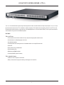
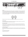
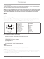
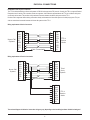
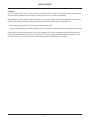
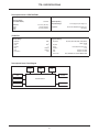
Vocia®
TTS-1 and TTS-1nc
Operation Manual
January 2013
Biamp Systems, 9300 SW Gemini Drive, Beaverton, Oregon 97008 U.S.A. (503) 641-7287 www.biamp.com
TABLE OF CONTENTS
VOCIA TEXT-TO-SPEECH SERVER 1 (TTS-1) FEATURES. . . . . . . . . . . . . . . . . . . . . . . . . . . . . . . . 3
SETUP AND USE . . . . . . . . . . . . . . . . . . . . . . . . . . . . . . . . . . . . . . . . . . . . . . . . . . . . . . . . . . . . . . . . . . . . . . . . . . . . . . . . 4
FRONT PANEL. . . . . . . . . . . . . . . . . . . . . . . . . . . . . . . . . . . . . . . . . . . . . . . . . . . . . . . . . . . . . . . . . . . . . . . . . . . . . . . . . . . 5
REAR PANEL. . . . . . . . . . . . . . . . . . . . . . . . . . . . . . . . . . . . . . . . . . . . . . . . . . . . . . . . . . . . . . . . . . . . . . . . . . . . . . . . . . 6-7
Device ID . . . . . . . . . . . . . . . . . . . . . . . . . . . . . . . . . . . . . . . . . . . . . . . . . . . . . . . . . . . . . . . . . . . . . . . . . . . . . . . . . . . . . .
Network Connection. . . . . . . . . . . . . . . . . . . . . . . . . . . . . . . . . . . . . . . . . . . . . . . . . . . . . . . . . . . . . . . . . . . . . . . . . . . . .
LAN-1 Connector (Control). . . . . . . . . . . . . . . . . . . . . . . . . . . . . . . . . . . . . . . . . . . . . . . . . . . . . . . . . . . . . . . . . . . . . . . .
LAN-2 Connector (CobraNet). . . . . . . . . . . . . . . . . . . . . . . . . . . . . . . . . . . . . . . . . . . . . . . . . . . . . . . . . . . . . . . . . . . . . .
LAN-3 and LAN-4 Connectors (Spares). . . . . . . . . . . . . . . . . . . . . . . . . . . . . . . . . . . . . . . . . . . . . . . . . . . . . . . . . . . . . .
AC Power Entrance (IEC). . . . . . . . . . . . . . . . . . . . . . . . . . . . . . . . . . . . . . . . . . . . . . . . . . . . . . . . . . . . . . . . . . . . . . . . .
USB Ports. . . . . . . . . . . . . . . . . . . . . . . . . . . . . . . . . . . . . . . . . . . . . . . . . . . . . . . . . . . . . . . . . . . . . . . . . . . . . . . . . . . . . .
RS-232 Port . . . . . . . . . . . . . . . . . . . . . . . . . . . . . . . . . . . . . . . . . . . . . . . . . . . . . . . . . . . . . . . . . . . . . . . . . . . . . . . . . . . .
VGA Port. . . . . . . . . . . . . . . . . . . . . . . . . . . . . . . . . . . . . . . . . . . . . . . . . . . . . . . . . . . . . . . . . . . . . . . . . . . . . . . . . . . . . . .
6
6
6
6
6
7
7
7
7
PHYSICAL CONNECTIONS. . . . . . . . . . . . . . . . . . . . . . . . . . . . . . . . . . . . . . . . . . . . . . . . . . . . . . . . . . . . . . . . . . . . 8
INSTALLATION. . . . . . . . . . . . . . . . . . . . . . . . . . . . . . . . . . . . . . . . . . . . . . . . . . . . . . . . . . . . . . . . . . . . . . . . . . . . . . . . . . . 9
SPECIFICATIONS & BLOCK DIAGRAM. . . . . . . . . . . . . . . . . . . . . . . . . . . . . . . . . . . . 10
WARRANTY . . . . . . . . . . . . . . . . . . . . . . . . . . . . . . . . . . . . . . . . . . . . . . . . . . . . . . . . . . 11
COMPLIANCE . . . . . . . . . . . . . . . . . . . . . . . . . . . . . . . . . . . . . . . . . . . . . . . . . . . . . . . . 12
2
VOCIA TEXT-TO-SPEECH SERVER 1 (TTS-1)
The TTS-1 is a networked text-to-speech engine that supports the creation of browser-based courtesy announcements. The TTS-1nc performs the same functions as the TTS-1 in addition it is able to integrate to TAP enabled nurse call systems. The TTS-1 and TTS-1nc use
Ethernet-based control protocols in conjunction with A Vocia Message Server 1 to function within a Biamp® Vocia® system and constructs
announcements using a set of user-defined templates.
FEATURES
TTS-1 and TTS-1nc
• Text-to-speech announcement creation from any computer with appropriate network access
• Announcements in multiple languages and voices
• User-defined templates
• CobraNet audio/control with dynamic use of available bundles over a single Ethernet cable
• Status LED
• Rotary switches for unit identification
• Rack mountable (1RU)
• CE marked and RoHS compliant
• Covered by BIAMP Systems’ warranty
TTS-1nc Specific Features
• Interface to nurse call system via RS-232C
• Ability to create rules and groups for delivery of messages via a Vocia MS-1
3
TTS-1 SETUP AND USE
Overview
The Vocia Text to Speech Server 1 (TTS-1) and The Vocia Text to Speech Server 1 Nurse Call (TTS-1nc) are designed to work in conjunction with a Vocia Message Server 1 (MS-1) to enable text to speech messaging as part of a Vocia system solution.
Voice fonts are available to suit regional languages.
The TTS-1nc also facilitates integration via RS-232 to Nurse call systems that make use of the TAP protocol. Rauland Responder 4 and 5
are supported natively.
Setup and Use
The Vocia software provides an intuitive interface for configuration of the TTS-1. In addition, the Vocia Text-to-Speech server supports a web
brower to enable user configuration of custom text strings. The information supplied by this manual relates to physical connections and assignment. For more details on software setup, please consult the Vocia Help File.
4
TTS-1 FRONT PANEL
Power/
Network
Front Panel
The TTS-1 features one power indication LED on the front panel:
1. Not illuminated: The device is not powered.
2. Flashing green: The unit is receiving power but not data, or the unit has not been configured correctly.
3. Solid green: The unit is operational. Power supply and network traffic are functional.
5
TTS-1 REAR PANEL
MSB
LSB
Device ID
LAN1: Control
LAN2: CobranetTM
LAN3: Spare
LAN4: Spare
O
Model TTS-1
BIAMP SYSTEMS
RS232 Port
AC Power
Entrance (IEC)
USB Ports
LAN-1
LAN-3
Device ID
(control)
(Spare)
LAN-2
LAN-4
(CobraNet) (Spare)
Device ID
The rotary ID switches are located on the back of the TTS-1 and give the unit a unique Device ID. The switches are in hexadecimal format.
All TTS-1 units must have a unique Device ID to function properly within a Vocia Paging World (i.e., it is not possible to have two TTS-1
units with the same Device ID of hex 07). To assign a Device ID of hex 07, turn the LSB switch to 7 and leave the MSB switch on
0. To create an ID of hex B7, turn the LSB switch to 7 and turn the MSB switch to B. Device ID switches should be set using a 0.1 inch
(2.5mm) to 0.12 inch (3.0mm) flat blade screwdriver. More information on setting IDs and the hexadecimal numbering scheme used in
Vocia can be found in the Vocia Help File.
Please note: Changes made to the Device ID while connected to the network require a power cycle in order to take effect.
Network Connection
The TTS-1 has four RJ45 Ethernet connectors located on the rear panel (Control, Vocia Network, and Spare). Each connector has two
green LEDs, which display Ethernet Link (left LED) and Activity (right LED).
LAN-1 Connector (Control)
This port connects the TTS-1 to a control network. This should be separate to the LAN that is being used by the CobraNet port either
physically or through the use of managed switches and VLANs. The TTS-1 can be configured in the Vocia software via this port, and as
such it should be connected to the same network as any Vocia Message Server 1 (MS-1) devices and computer running Vocia Software.
The Default IP address is 192.168.1.201.
LAN-2 Connector (CobraNet)
This port is used to communicate with local Vocia devices and as such should be connected to the same network as the local Vocia system. The data from the CobraNet network should be placed on its own LAN, either physically or through the use of managed switches and
VLANs.
LAN-3 and LAN-4 Connectors (Spares)
These ports are inactive at this time.
6
TTS-1 REAR PANEL
AC Power Entrance (IEC)
The IEC power entrance provides for connection of the appropriate power cord (included with unit). An internal universal switching power
supply accepts 100–240VAC @ 50/60Hz, with a maximum power consumption of 350 watts.
CAUTION: Do not remove or defeat the ground prong on the power cord, as this will constitute a shock hazard. Equipment should be connected
to a mains socket outlet with a protective earthing connection. This plug is the main disconnecting device and should remain readily operable.
There are no user interchangeable parts. Please contact Biamp Technical Support or your local distributor for all service requirements.
USB Ports
These ports are inactive at this time.
RS-232 Port
This port is is not used for the TTS-1.
This port is used for the TTS-1nc to facilitate interfacing to a external nurse call system. The port interfaces to a TAP enabled device in
order to generate Text to Speech or recorded messages or play specified configured Vocia Page Codes. The Vocia software allows customization of the rules and messages. Please refer to the RS-232 Physical connections section for cabling details.
1
5
9
6
Male DB-9
On TTS-1
1 DCD Carrier Detect
2 RxD Receive Data
3 TxD Transmit Data
4 DTR Data Terminal Ready
5 SG Signal Ground
6 DSR Data Set Ready
7 RTS Request To Send
8 CTS Clear To Send
9 RI Ring Indicator
Default Settings:
Baud Rate 9600
Stop Bits 1
Parity None
Data Bits 8
RTS Enabled
DTR Enabled
Flow Control RTS
Nurse Call RS-232 Serial Port Options supported settings:
• Baud Rate can be set to - 300, 1200, 2400, 4800, 9600, 19200, 38400, 57600, 115200.
• Stop bits can be set to 1 or 2.
• Parity can be set to None, Odd, Even, Mark, Space.
• Data Bits can be set to 7 or 8.
• RTS and DTR can be enabled or disabled.
• Flow Control can be None, XOn/XOff, RTS and RTS XOff/RTS XOn.
VGA Port
This port is inactive at this time.
Please note: connection of external devices to inactive ports is not required or recommended.
WARNING: Replacing the Lithium Battery
Incorrect replacement of the lithium battery may lead to a risk of explosion. The lithium battery must be replaced with an identical battery
or a battery type recommended by the manufacturer. Do not throw lithium batteries into the trash can. They must be disposed of in
accordance with local regulations concerning special waste.
7
PHYSICAL CONNECTIONS
RS-232 Nurse Call Physical Connection
The TTS-1nc allows interfacing to Nurse call systems via RS-232 and supports the TAP protocol. Currently the TTS-1nc supports Rauland
Responder 4 and 5 natively. Two connection modes are supported. Active Mode is supported where the TTS-1nc and Nurse call system
are the only devices used. This provides a fully monitored connection between the Nurse call system and the TTS-1.
Passive mode is supported where existing connections already exist between the Nurse Call system and a third party system. This provides an unmonitored connection between the Nurse call system and the TTS-1.
Wiring requirements of Active Connection
CD
RxD
TxD
DTR
SG
DSR
RTS
CTS
RI
Nurse Call
System
1
2
3
4
5
6
7
8
9
1
2
3
4
5
6
7
8
9
Not Connected
D-9 Female
CD
RxD
TxD
DTR
SG
DSR
RTS
CTS
RI
TTS-1
Active
Mode
D-9 Female
Wiring requirements of Passive Connection
Nurse Call
System
CD
RxD
TxD
DTR
SG
DSR
RTS
CTS
RI
1
2
3
4
5
6
7
8
9
1
2
3
4
5
6
7
8
9
Not Connected
D-9 Female
CD
RxD
TxD
DTR
SG
DSR
RTS
CTS
RI
Third
Party
System
D-9 Female
1
2
3
4
5
6
7
8
9
CD
RxD
TxD
DTR
SG
DSR
RTS
CTS
RI
TTS-1
Passive
Mode
D-9 Female
The enclosed diagram is indicative. Connection wiring may vary depending on the interfacing hardware. Suitable isolating and
8
INSTALLATION
Installation
The TTS-1 requires one 1.75 inch (44.45 mm) high and 19 inch (483 mm) wide rack space with 17inch (432 mm) depth. Mounting the unit
using four screws with washers will prevent marring of the front panel. PVC or nylon washers are appropriate.
When installing the rack ears, please note that the hardware is not symmetrical. Please install the rack ear labeled “left” on the left side of
the TTS-1 (when looking at the equipment facing the front plate) and the rack ear labeled “right” to the right of the unit.
•First, remove the screw from the TTS-1 chassis (with a Phillips P2 screw driver)
•A
ttach the appropriate rack ear and re-affix the Phillips screw to the chassis and 4 additional Philips screws supplied with the rack ears.
Please install the unit away from heat sources, such as vents and radiators, and in rooms with adequate ventilation. Ensure that air can
circulate freely behind, beside, and above the unit. Do not exceed the maximum ambient operating temperature of 113 degrees F (45°C).
Be aware of conditions in an enclosed rack that may cause the temperature to exceed ambient room conditions.
9
TTS-1 SPECIFICATIONS
Text-to-Speech Server 1 SPECIFICATIONS
Default IP address
Power Consumption
(100–240VAC 50/60Hz):
Weight:
192.168.1.201
Ambient Operating
Temperature Range:
< 350 watts
Dimensions:
Height:
Width:
Depth:
12 lb (5.4 kg)
0.75 inches (44.5 mm)
19 inches (483 mm)
17.5 inches (444 mm)
32-113 degrees F (0-45 degrees C)
Compliance:
EU Directive 2002/95/EC, RoHS directive
CE marked
RS-232 Port
Default Settings
Baud Rate
Stop Bits
Parity
Data Bits
RTS
DTR
Flow Control
Supported Settings
Baud Rate
9600
1
None
8
Enabled
Enabled
RTS
Stop Bits
Parity
Data Bits
RTS
DTR
Flow Control
300, 1200, 2400, 4800, 9600, 19200, 38400,
57600, 115200
1 or 2
None, Odd, Even, Mark, Space
7 or 8
Enabled or Disabled
Enabled or Disabled
None, XOn/XOff, RTS and RTS XOff/RTS XOn
Text-to-Speech Server 1 Block Diagram
RS-232
USB
VGA
LED
ID Switches
Control
Host Processor
Storage Drive
CobraNet®
10
TTS-1 WARRANTY
BIAMP SYSTEMS IS PLEASED TO EXTEND THE FOLLOWING 5-YEAR LIMITED WARRANTY TO THE ORIGINAL PURCHASER OF
THE PROFESSIONAL SOUND EQUIPMENT DESCRIBED IN THIS MANUAL
1. BIAMP Systems warrants to the original purchaser of new products that the product will be free from defects in material and
workmanship for a period of 5 YEARS from the date of purchase from an authorized BIAMP Systems dealer, subject to the
terms and conditions set forth below.
2 If you notify BIAMP during the warranty period that a BIAMP Systems product fails to comply with the warranty, BIAMP Systems
will repair or replace, at BIAMP Systems’ option, the nonconforming product. As a condition to receiving the benefits of this warranty,
you must provide BIAMP Systems with documentation that establishes that you were the original purchaser of the products. Such
evidence may consist of your sales receipt from an authorized BIAMP Systems dealer. Transportation and insurance charges to
and from the BIAMP Systems factory for warranty service shall be your responsibility.
3. This warranty will be VOID if the serial number has been removed or defaced; or if the product has been altered, subjected to
damage, abuse or rental usage, repaired by any person not authorized by BIAMP Systems to make repairs; or installed in any
manner that does not comply with BIAMP Systems’ recommendations.
4. Electro-mechanical fans, electrolytic capacitors, gooseneck microphones, cords connecting handheld microphones, hard-drives,
displays, and normal wear and tear of items such as paint, knobs, handles, keypads and covers are not covered under this warranty. All server-based devices are warranted for 3 years only.
5. This warranty is in lieu of all other warranties, expressed or implied. BIAMP Systems disclaims all other warranties, expressed or
implied, including, but not limited to, implied warranties of merchantability and fitness for a particular purpose.
6. The remedies set forth herein shall be the purchaser’s sole and exclusive remedies with respect to any defective product.
7. No agent, employee, distributor or dealer of BIAMP Systems is authorized to modify this warranty or to make additional warranties on behalf of BIAMP Systems. Statements, representations or warranties made by any dealer do not constitute warranties by
BIAMP Systems. BIAMP Systems shall not be responsible or liable for any statement, representation or warranty made by any
dealer or other person.
8. No action for breach of this warranty may be commenced more than one year after the expiration of this warranty.
9. BIAMP Systems shall not be liable for special, indirect, incidental, or consequential damages, including lost profits or loss of use arising out of the purchase, sale, or use of the products, even if BIAMP Systems was advised of the possibility of such damages.
013013_ 585.0298.90C
11
COMPLIANCE
12