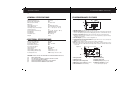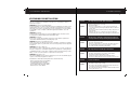
1
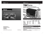
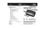
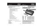
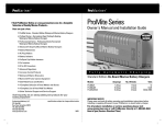
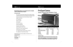
On Board
ProMa r i ne r
Solutions
™
A ProMariner Company
Visit ProMariner Online at www.promariner.com, for a Complete
Selection of Quality Marine Products...
Here are just a few:
On Board
ProMa r i ne r
Solutions
™
A ProMariner Company
TruePower400PS Series
Owner's Manual and Installation Guide
ProMite Series - Recreational Grade Waterproof Marine Battery Chargers
ProTournament Series - Professional Grade Waterproof Marine
Battery Chargers
ProNautic C3 Series All Digital Dry Mount Battery Chargers
ProTech-i Series Dry Mount Battery Chargers
Digital Mobile Charge In-Transit Chargers
Battery Maintainers
AC Plug Holders
Battery Isolators
Isolation Transformers
Galvanic Isolators and Monitored Systems
D C
Corrosion Control Products
A C
P o w e r
I n v e r t e r
400 Watt Inverter with Automatic Crossover
Waterproof Marine Binoculars
Models
A Complete Line of Hand Held Test Meters
TruePower400PS
TruePower400PS
Online Technical Support and Service Support
Part No.
79400
79405
Description
GFCI Protected Outlets
Hardwired
IMPORTANT SAFETY NOTICE
SAVE THESE INSTRUCTIONS
Visit frequently, we are always adding new products for your
boating enjoyment!
Factory Service
TEL: 1-800-824-0524
www.promariner.com
8:30 - 5:00 Eastern Time
200 International Drive, STE 195
Portsmouth, NH 03801
t o
specifications subject to change without notice
Please read all safety, operating and installation instructions before installing
or applying AC power to your ProMariner / On Board Solutions power inverter.
For all product, installation or service questions please visit
www.promariner.com or call ProMariner directly at: 1-800-824-0524
8:30 am to 5pm (Eastern Time)
090308
TABLE OF CONTENTS
Safety Instructions...
TruePower400PS Overview...
TruePower400PS Features...
Installation Guidelines...
Operation...
Troubleshooting...
Specifications...
Customer Service and Warranty...
Page 1 - 2
Page 2
Page 3 - 4
Page 5 - 10
Page 11 - 12
Page 13
Page 14
Page 15
INTRODUCTION
Thank you from all of us at Professional Mariner and Onboard Solutions.
Congratulations on your recent purchase of the TruePower400PS Power Inverter!
For over 30 years ProMariner has been a leading designer and manufacturer of
power conversion products. On Board Solutions serves customers in the automotive,
recreational vehicle, industrial and mobility markets and is a proud division of
ProMariner. We have expanded our offering to include our latest line of
TruePower400PS Power Inverters.
Please save and read this manual carefully and fully understand the safety
instructions before installing your new TruePower400PS Power Inverter.
Safety Instructions
1
GENERAL SAFETY INSTRUCTIONS
Before installing and using your new inverter, read all appropriate sections of this guide
and any cautionary markings on the inverter, batteries and on your appliances.
1) SAVE THESE INSTRUCTIONS
This manual contains important safety and operating instructions for inverter models
79400 and 79405.
2) CAUTION:
Do not operate the inverter if the carton or unit has significant damage from being dropped
or crushed, received a direct hit of force or is otherwise damaged.
3) CAUTION:
Do not dismantle the inverter. Call the factory directly when service or repair is required.
Incorrect assembly may result in risk of electrical shock or fire.
4) CAUTION:
To reduce the risk of electrical shock, disconnect both AC and DC power from the inverter
prior to any maintenance or cleaning.
5) CAUTION:
Protect the inverter from rain, snow, water and spray.
6) CAUTION:
Use of an attachment not recommended or sold by ProMariner my result in a risk
of fire, electric shock, or injury to persons.
7) CAUTION:
Connect and disconnect DC output connections ONLY after setting any inverter
switches to the off position and removing any AC or shorepower cords from electric
outlet or opening an AC disconnect.
PERSONAL SAFETY PRECAUTIONS
Someone should be within the range of your voice or close enough to come to your aid
when installing power inverters or working near lead acid batteries.
Wear complete eye protection and protective clothing. Avoid touching eyes while working
on or with batteries. Have plenty of soap and water nearby in case of battery acid comes
in contact with skin, clothing or eyes.
If battery acid comes in contact with skin or clothing, wash immediately with soap and
water. If acid enters the eye (s) flood eye (s) with running water for at least 10 minutes and
get medical attention immediately.
TruePower400PS Overview
2
PERSONAL SAFETY PRECAUTIONS CONTINUED
Never smoke or allow a spark or a flame in the vicinity of a battery or engine.
Be extra cautious to reduce the risk of dropping a metal tool onto a battery. It may spark
or short-circuit the battery or other electrical parts that may cause an explosion.
Remove all personal metal items such as rings, bracelets, necklaces, watches and jewelry
when working near a battery. A battery can produce a short circuit high enough to weld
a ring or any metal, causing serious burns.
Never charge a frozen battery.
WARNING: RESTRICTIONS ON USE
The TruePower400PS sine wave inverter shall not be used in connection with life support
systems or other medical equipment devices.
GUIDE TO OPERATION
General Advisory
Install your TruePower400PS Inverter to the guidelines recommended in this manual.
The TruePower400PS Inverter is designed to meet UL 458.
General Operation
The TruePower400PS Inverter is a sine wave inverter which converts 12 volt directcurrent (DC) power from your batteries to 120 volts alternating current (AC) power. This
AC power is the same quality as the electricity you get from your utility. The TruePower400PS
Inverter comes equipped with numerous protection features to guarantee safe and
worry-free operation.
GENERAL OVERVIEW
The TruePower400PS provides 400 watts of clean sine wave AC power for your sensitive
entertainment electronics.
Offering superior quality sine wave output, the TruePower400PS sine wave inverter is
designed to power entertainment systems in boats and recreational vehicles. Its clean
utility-grade output does not produce noise and distortion on televisions, LCD and Plasma
TV’s, VCR’s, DVD’s and stereo’s. The TruePower400PS supplies up to 400 watts of
continuous power and with a surge rating of 1000 watts, it can power complete
entertainment systems including two 27” televisions, or it could also power small appliances,
chargers, and power tools.
The TruePower400PS sine wave inverter includes a built-in transfer switch that
automatically transfers between inverter and incoming AC power. The inverter comes
standard with dual AC outlets and AC hardwire connections that increase installation
options and safety.
TruePower400PS Features
Customer Service & Warranty
3
16
INVERTER FEATURES
CUSTOMER SERVICE & WARRANTY
Product Features
We are committed to customer satisfaction and value your business. If at any time
during the warranty period you experience a problem with your new TruePower400PS
inverter simply call us at 1-800-824-0524 during standard business hours (8:30 AM –
5 PM Eastern Standard Time) for technical support.
- 400 watt inverter with 1000 watt surge provides sufficient power for entertainments systems
- Built-in transfer switch automatically transfers between inverter power and
incoming AC power, rated at 10 Amps
- Certified to UL 458
- Dual GFCI protected AC outlets and hardwire AC connections
- Flush mount remote control with 3 meter cable
- Filtered sine wave output will not produce distortion on sensitive electronics
- One year warranty
- Part number # 79400 with plugs and Part number # 79405 for hardwired only
- Remote control panel with status indicator
Protective Features
- Automatic overload protection
- Battery over-voltage and under-voltage protection
- Ground Fault Protection (GFCI)
- Over temperature shutdown
- Short circuit protection
PROTECTION FEATURES
Low Voltage Shutdown protects the battery from becoming completely discharged by
shutting down automatically if the input voltage drops below 10.5 volts. The TruePower400PS
recovers automatically when the input voltage comes up to 12.4.
High Voltage Shutdown protects the TruePower400PS by disabling the AC output when the
input voltage rises to 15.6 volts or more. The AC output is enabled when the input voltage drops
to 15.5 volts. Over-temperature Shutdown disables the AC output of the TruePower400PS
when the internal temperature rises or overloading occurs. The TruePower400PS recovers
automatically after it cools down.
Overload Protection disables the AC output of the TruePower400PS if the appliance
connected to the inverter exceeds the 400 watt rating of the inverter. The TruePower400PS
will then automatically reset after the overload has been removed.
Short Circuit Protection disables the AC output of the TruePower400PS when a short
circuit is applied on the last AC output. Once the short circuit is cleared, the TruePower400PS
will automatically be reset.
(GFCI) Ground Fault Circuit Interrupter trips and disables the output of the TruePower400PS
when a ground fault current is detected. The output can be enabled again by resetting
the GFCI, once the ground fault is cleared. (GFCI is available in the 79400 model only)
TruePower 400PS
One Year Limited Factory Warranty
& Lifetime Repair or Replacement Policy
Each TruePower400PS model is guaranteed against defects in material and workmanship to the original consumer
in normal use for 1 year from the date of purchase. Professional Mariner, LLC will at it's discretion repair or
replace free of charge any defects in material or workmanship. The following conditions apply:
• Warranty is calculated from manufacture date if not registered within
30 days of purchase.
• Warranty void if unauthorized repairs attempted.
• Customer is responsible for returning the product to Professional Mariner, LLC.
Inbound shipping costs must be paid by customer.
• This warranty does not cover blemishes due to normal wear and tear or
damaged caused by accidents, abuse, alterations or misuse.
• Cosmetic repairs can be done at owner's request and expense.
Purchase or other acceptance of the product shall be on the condition and agreement that Professional Mariner
SHALL NOT BE LIABLE FOR INCIDENTAL OR CONSEQUENTIAL DAMAGES OF ANY KIND. (Some states do not
allow the exclusion or limitation of incidental or consequential damages, so the above limitations may not apply
to you.) Professional Mariner neither assumes nor authorizes any person for any obligation or liability in connection
with the sale of this product.
To make a claim under warranty, call 1-800-824-0524 or visit www.promariner.com indentifying the product and
giving its locations. Follow the company's return instructions, which will then be provided by the company.
Professional Mariner will make its best effort to repair or replace the product, if found defective within the terms
of the warranty, within (30) days after return of the product to the company. Professional Mariner will ship the
repaired or replaced product back to the purchaser.
After the 1 year limited factory warranty expires, all product replacement is pro-rated based on list price and
will never exceed 50% of list price.
This warranty gives you specific legal rights, and you may also have other rights, which vary from state to state.
This warranty is in lieu of all others expressed or implied.
Factory Service Center & Technical Offices
Professional Mariner, LLC
200 International Drive STE 195
Portsmouth, NH 03801
Tel: 1-800-824-0524 www.promariner.com
Professional Mariner, LLC Headquarters
Tel: (603) 433-4440 / Fax: (603) 433-4442
Specifications
TruePower400PS Features
4
15
ELECTRICAL SPECIFICATIONS
Battery Low Shutdown:
Continue Output Power:
Input Voltage Range:
Input Full Load Current:
No Load Power Draw
Output Frequency:
Output Power:
Output Voltage (At No Load):
Output Voltage (At Full Load):
Peak Output Power:
10.5 VDC
400 W
10.5 – 15.3 VDC
40 A
0.5 A
60 +/- 0.05 Hz
400 Watts
120 Vac Rms +/- 3 V
120 Vac Rms +/- 5 V
1000 Va Surge For 5 Seconds
Figure 1
4
6
7
AC SHORE
BREAKER
RESET
RESET
2 – Dual Three-prong
Yes (Fuse)
70 A
13 x 6.25 x 3.75
88%
Yes (Button Breaker)
Pure Sine Wave (<3% Thd)
32° F – 158° F (0° Fc – 40° C)
Yes
-22° F - 158° F (-30° C – 70° C)
79400 With Outlets
79405 Hardwired
50 +/-5 Deg C
13 Lbs
TEST
AC Receptacle:
Battery Polarity Protect:
DC Fuse (Recommended):
Dimension (L x W x H):
Efficiency:
Output Short Protect:
Output Waveform:
Operating Temperature Range:
Overload Protect:
Storage Temperature Range:
Part Number:
Part Number:
Thermal Protect:
Weight:
TRUEPOWER 400PS FEATURES
TEST
GENERAL SPECIFICATIONS
POWER
POWER STATUS
Shore ON
Green: Inverter ON
Red: Inverter Fault
3
2
5
1
1. ON / Off Switch turns the inverter to ON or to OFF.
2. Shore Power light illuminates when you are connected to shorepower. (shorepower
refers to the AC input power from a utility grid, generator or external AC source)
3. Inverter / Fault Light illuminates Green when the inverter is operating and
illuminates Red for fault conditions such as over temperature, output overload,
or battery over voltage.
4. Two AC Outputs to power connected appliances.
5. Supplemental Circuit Protection Button may trip if there is an over-current (over
10 amps) or a short circuit.
6. GFCI opening enables the Reset and Test monthly capabilities.
7. Fan (internal) activates when the internal temperature of the inverter increases.
The fan speed varies with the internal temperature and turns off when the inverter
cools down.
4
2
Figure 2
9
AC Output
Remote
DC Input
AC Input
8
5
DC Grounding
Connector
CAUTION: ALWAYS PLACE THE INVERTER IN AN ENVIRONMENT WHICH IS:
1
(A)
(B)
(C)
(D)
(E)
WELL VENTILATED
NOT EXPOSED TO DIRECT SUNLIGHT OR HEAT SOURCE
OUT OF REACH FROM CHILDREN
AWAY FROM WATER / MOISTURE, OIL OR GREASE
AWAY FROM ANY FLAMMABLE SUBSTANCE
6
1. DC Input Cables
2. AC Receptacles
3. AC Input cord for shorepower
4. Wiring box access panel (Top panel)
5. AC Strain Relief for hardwiring
3
7
6. Chassis ground lug
7. Remote control jack
8. Mounting flanges (Side panel)
9. Ventilation openings provides
air circulation (Side panel)
Tr o u b l e s h o o t i n g
Installation Guidelines
5
14
PREPARING FOR INSTALLATION
Problem:
No output voltage. Inverter light is illuminated.
Cause:
Inverter may be overloaded.
Battery voltage may be too high.
Over temperature.
Solution:
-Disconnect all appliances connected to the inverter &
reset the inverter by turning the ON/Off switch to Off then
back to ON.
-The inverter will restart if the battery voltage drops below
15.5 volts DC.
-Allow the inverter to cool down. The inverter will start
automatically. No output voltage. NO Lights are illuminated.
WARNING: Fire Hazard
Do not cover or obstruct the ventilation openings. Do not install this equipment in a
compartment with limited airflow; Overheating may result.
Problem:
AC input cord is connected to shorepower, but appliance(s)
are not powered from shorepower. AC Input light is illuminated.
Cause:
GFCI has tripped.
WARNING: This devise is not Ignition Protected
Avoid serious injury or death from explosion. Do not install in compartments containing
gasoline fueled engines or gasoline tank, or in areas where ignition protected equipment
is required.
Solution:
-Reset the external breaker
-Disconnect all appliances. Check the AC wiring and press
the supplemental circuit protection button to reset it.
-Clear the ground fault and reset the GFCI.
Problem:
No output voltage. Fault LED light is illuminated.
Cause:
Poor DC wiring.
Solution:
-Recharge the batteries to more than 12.6 volts DC.
The inverter will automatically restart.
-Turn the inverter to Off. Disconnect the DC wiring.
Use proper wiring and ensure all connections are secure.
Problem:
Fan runs all the time.
Cause:
The power rating of the appliance is too high.
The ambient temperature is high.
Solution:
-No action. The fan will run at full speed when the inverter
is powering a higher rated appliance.
-No action. The fan will run at a higher ambient temperature
to keep the inverter cool.
Read this entire installation section so you can plan the installation from beginning to
end. Prior to beginning your installation, review the “Personal Safety Precautions”
information on page 2.
WARNING: Electrical shock and fire hazards
Professional Mariner recommends all wiring be done by qualified personnel. Disconnect
all AC and DC power sources to prevent accidental shock. Disable and secure all AC
and DC disconnect devices and automatic generator starting devices. It is the installer’s
responsibility to ensure compliance with all the applicable installation codes and
regulations.
WARNING: Fire Hazard
To meet regulatory requirements, the TruePower400PS must be mounted on a flat
horizontal surface with the label panel in the upright position.
WARNING: Risk of Fire or Explosion
This equipment contains components that could produce arcs or sparks. To reduce the
risk of fire or explosion, do not install this equipment in compartments containing batteries
or flammable materials, or in a location containing gasoline-powered machinery, or joints,
fittings, or other connections between components of the fuel system.
WARNING: Restrictions on Use
The TruePower400PS sine wave inverter shall not be used in connection with life support
systems or other medical equipment or devices.
Installation Recommendations & Requirements include the following:
- American Boat and Yacht Council (ABYC)
- The Canadian Electrical Code (CEC)
- Canadian Standards Association (CSA)
- The U.S. National Electrical Code (NEC)
- RV Industry Association (RVIA)
Installation Guidelines
Tr o u b l e s h o o t i n g
13
6
TROUBLE SHOOTING GUIDE
MOUNTING YOUR INVERTER
This section is designed to accommodate you in identifying and troubleshooting
common problems that may result with a Sine Wave inverter. Review this section
before contacting customer service. If you can not resolve the problem, record the
data of the instance based on information provided here with in this manual.
To mount the TruePower400PS Inverter:
1. Turn the On/Off switch on the front panel of the inverter to Off position.
2. Select an appropriate mounting location and orientation.
3. Hold the inverter against the mounting surface, mark the position of the mounting
screws, and then remove the inverter.
4. Drill pilot holes for the four mounting fasteners.
5. Fasten the inverter to the mounting surface with four #10 hardware fasteners.
Mount your inverter prior to connecting any wires or cables: For the best load starting performance,
the DC cables should be short and large as possible. See table 3 for minimum recommended
cable size. Using a smaller cable may cause the inverter to shut down under a heavy load.
This troubleshooting section will aid you in identifying the source of common
problems you may encounter. If you are unable to resolve the problem from the
troubleshooting reference table, contact your dealer or customer service.
331mm
Figure 6
Cause:
The switch is in Off position.
No input power to the inverter.
DC fuse is open.
Solution:
-Turn the ON/Off switch to the ON position.
-Check the DC wiring to the inverter for loose connections
or frayed wiring.
-Have a qualified service technician check & replace the fuse.
32mm
63.25mm
150.5mm
No output voltage. No indicator lights are illuminated.
AC OUTPUT
WIRING
Problem:
267mm
163.5mm
WARNING: Electrical shock and fire hazards. Professional Mariner recommends
that all wiring be done by qualified personnel. Disconnect all AC and DC power
sources to prevent accidental shock. Please do not attempt to disassemble the
TruePower400PS inverter. It does not contain any user-serviceable parts. Attempting
to service the unit yourself could result in electrical shock or fire.
L
N
G
Minimum Recommended DC Input cable (copper) – AWG
Problem:
No output voltage. Inverter light is illuminated.
Cause:
Circuit breaker has tripped.
GFCI has tripped.
Solution:
-Disconnect all appliances to reduce the overload, check
the AC wiring, and reset the breaker by turning the ON/Off
switch to Off and then back to ON.
-Clear the ground fault, and reset the GFCI by pressing the
reset on the GFCI button.
Problem:
Fan does not turn on.
Cause:
The power rating of the appliance may be too low or the
ambient temperature is too cool.
Solution:
-No action. The fan will run at full speed when the inverter
is powering a higher rated appliance.
Cable Length: Battery to Inverter
(Each Cable)
Minimum Recommended
Cable Size – AWG
0 – 10 Feet
10 – 15 Feet
15 – 30 Feet
30 – 40 Feet
No.
No.
No.
No.
6
4
2
0
DC Fuse and Disconnect or DC Circuit Breaker: The DC fuse and disconnect switch or
the DC circuit breaker shall be rated 60 amps. Additionally, the fuse type must be selected
to match code requirements.
Connecting the Chassis Ground: The chassis ground lug is used to connect the chassis
of the inverter to your system’s chassis grounding point, as required by installation codes.
Use copper cable that is provided with green insulation. Do not use the chassis ground
lug for your AC output grounding wire.
Installation Guidelines
General Operation
12
7
INSTALLATION CONTINUED
OPERATION CONTINUED
To Connect the Chassis Ground: Refer to figure 3
Resetting the Inverter: To reset the TruePower400PS, turn the ON/Off switch to Off and
then back to ON.
Figure 3
DC Input
Remote
Resetting the Supplemental Circuit Protection Button: If there is a short circuit or an
overload condition, the supplemental circuit protection button trips. To reset the TruePower400PS,
clear the overload condition then press the supplemental circuit protection button.
Ground
Termination
Resetting the Ground Fault Circuit Interrupter (GFCI): Function- The GFCI receptacle
protects the receptacle output against a ground fault.
DC Grounding
Connector
1.Using the #3 standard Phillips screwdriver, loosen the screw on the chassis ground lug.
2.Using a #8 Ring Terminal connect a No. 8 AWG copper cable between the inverter’s
chassis ground lug and the DC grounding point for your system. Tighten the screw to a
torque of 15 inch pounds.
Monthly Testing - Once a month, with either shorepower or the TruePower400PS turned
ON, press the Test button on the GFCI receptacle. The Reset button should trip. Press
it to reset the GFCI and to continue with normal operation. If the Reset button does not
trip, the GFCI may have failed. Contact your dealer or ProMariner to have a qualified
technician inspect the unit.
Connecting the DC Cables: Refer to figure 4
AC OUTPUT WIRING
AC OUTPUT WIRING
L
N
G
L
N
G
Battery
Battery
Figure 4
Correcting a Ground When a ground fault condition is detected, the Reset button on the
GFCI receptacle Fault- will trip and the power to an appliance is interrupted. To resume
normal operation, determine and correct the ground fault, then press the Reset button.
7" Maximum
Distance
from battery
7" Maximum
Distance
from battery
Resetting as the Result of an Overload:
The TruePower400PS has a high surge capacity of 1000 watts for 5 seconds.
If the appliance(s) connected to the unit try to draw excess power for more than
5 seconds, the TruePower400PS will shut down and the Red Fault light will illuminate.
After removing the overload condition, the TruePower400PS will cycle through a
15 second self check and automatically reset to operating levels.
Battery Switch
Figure 4 - Connecting the DC Cables
1. Switch the inverter On/Off switch to the Off position.
2. Route the DC cables from the inverter towards the battery.
3. Using a #8 AWG or larger red wire install a 70 Amp DC fuse or a DC circuit breaker
within 7 inches of the battery or battery switch as shown in fig. 4. Remove the fuse or
switch off the breaker for the remainder of the installation.
4. Connect the RED positive (+) lead coming from the inverter DC input to the output
side of the fuse or circuit breaker. Tighten the connection terminals to the
manufacturer’s recommendations. Test that the cable is secure.
5. Connect the BLACK negative (-) lead coming from the inverter DC input to the
negative battery terminal [or to the current shunt if an amp hour counting device is
used. Tighten the connection terminals to the manufacturer’s recommendations.
Test that the cable is secure.
Operating Several Appliances at the Same Time:
If you are going to operate several appliances from the TruePower400PS at the
same time, turn them on independently, after you have powered up the inverter.
This action ensures that the TruePower400PS does not have to deliver the starting
current for all of the appliances at once. The TruePower400PS can accommodate
several appliances at once as long as they do not exceed more than a combined
total of 400 watts.
Recharging Your Batteries:
We recommend you recharge your batteries before they are 50% discharged. This
will provide a much longer life cycle than recharging them when they are almost
completely discharged. It is recommended to use a Remote Battery Status indicator
to monitor the battery levels and determine optimum recharge times and cycles.
General Operation
Installation Guidelines
11
8
OPERATION
INSTALLATION CONTINUED
The ON/Off switch turns the TruePower400 PS to ON or to Off.
- In the ON position, the Inverter / Fault LED light will illuminate Green. The TruePower400PS
begins inverting and provides 400 watts of sine wave power, if shorepower is not present.
- In the Off position with no shorepower present, the TruePower400PS draws no current
from the battery.
- In the Off position with the AC input cord plugged into shorepower, the AC Input LED
light illuminates Green and the appliances connected to the TruePower400PS inverter
can be operated.
6. Check that the polarity of the DC connections are correct: RED to positive (+) at
the battery and BLACK to negative (-) at the battery.
7. Replace the fuse and/or switch on the breaker. A small spark is normal when this
connection is made.
NOTE: When the ON/Off switch is in the Off position with the TruePower400PS
connected to shorepower, AC voltage will be present at the output.
LED Indicators: The two indicator lights on the front panel of the inverter illustrate the
operating status of the TruePower400PS. See table 4 below.
Table 4 ~ Status of Indicator Lights
Hardwiring the AC Output:
WARNING: Fire, Shock and Energy Hazards
Make sure wiring is disconnected from all electrical sources before handling. All
wiring must be done in accordance with local and national wiring codes. Do not
connect the output leads of the inverter to any incoming AC source.
To Hardwire the AC Output Connections:
1. Turn the inverter On/Off switch to Off.
2. Locate the wiring box access panel, and remove the two screws to access the
wiring box as illustrated in Figure 5.
Figure 5
Light
Color
Status
Result
Shorepower
ON
Green
When the TruePower400PS is
connected to shorepower, the AC
Input illuminates.
Can run all your appliances from
shorepower.
Inverter/Fault
Green
When the TruePower400PS unit
is on, the Inverter light illuminates.
Can run your appliances through the
TruePower400PS from the battery.
The Fault light illuminates
whenever there is a battery overvoltage fault condition (in excess
of 15.6 volts), an output overload
condition or over-temperature
fault condition.
Can not run appliances as the AC
output is disabled in the invert mode.
Clear the fault condition. Reset the
TruePower400PS by turning the ON/Off
switch to Off and then back to ON, or
by connecting to shorepower.
Inverter/Fault
Red
Access screw location
Access screw location
AC OUTPUT WIRING
L Line
N Neutral
G Ground
14 or 16 ga.
3 conductors
Stranded
AC OUTPUT WIRING
L Line
N Neutral
G Ground
14 or 16 ga.
3 conductors
Solid
Stranded Wire
Solid Wire
Figure 5 ~ Removing the Two Screws on the Wiring Box Access Panel
3. Remove the wiring box access panel from the unit.
4. Loosen the clamping nut of the Strain Relief.
5. Locate the terminal block.
The three terminals are labeled as follows;
- L Line
- N Neutral
- G Ground
6. Strip about 2 inches off the jacket of the AC output cable. The AC output cable
must be with in range of No. 14 to No. 16 AWG, have three conductors and be solid
or stranded.
Installation Guidelines
Installation Guidelines
9
10
INSTALLATION CONTINUED
INSTALLATION CONTINUED
7. Strip approximately 3/8 inch off the insulation of the cable.
8. Run the AC cable through the clamp and into the wiring box.
9. Using a screwdriver, loosen the wire attachment screws on the terminals by
about five turns.
10. Insert and fasten the Ground wire into the corresponding terminal.
11. Insert and fasten the Line and Neutral wires into the corresponding terminals.
12. Tighten the Strain Relief screws, leaving some slack inside the output wiring box.
To test the TruePower400PS Inverter:
1. Turn the On/Off switch to the ON position. The Inverter/Fault LED light illuminates Green.
2. Plug an appliance of 400 watts or less into the AC outlet.
3. Turn the appliance ON to verify that it operates.
4. If the Inverter/Fault light illuminates Red, see the TruePower400PS Inverter
“Troubleshooting” section.
Note: If using standard wire it is recommended that you use proper crimp terminal connectors.
Chassis Ground Connection
Using a length of wire no smaller than one size smaller than the DC power cables. Connect
one end of this cable to the DC grounding connector at the inverter and the other end to
the vehicle chassis or bending system
PERFORMING CHECKS PRIOR TO INSTALLATION
Before starting up your inverter, ensure these conditions are met:
- Verify the chassis ground is properly installed.
- Verify the On/Off switch is in the Off position.
- Verify the Positive (+) battery cable is connected to the positive (+) battery terminal.
- Verify the Negative (-) battery cable is connected to the negative (-) battery terminal.
- Verify the battery voltage is within the proper range for this unit (10.5-15.3 volts DC).
- Verify the DC fuse is intact.
PERFORMING CHECKS PRIOR TO INVERTER START-UP
Shorepower Mode: When the shorepower source is connected, the TruePower400PS
inverter transfers the appliances to the shorepower source and goes directly into
shorepower mode. The AC Input LED light illuminates Green. The inverter will transfer
power with the ON/Off switch in either the ON or Off position.
Inverter Mode: If the ON/Off switch is in the ON position, the TruePower400PS will
automatically supply the appliance(s) with the inverter power if the shorepower source
fails or becomes disconnected.
INSTALLING YOUR REMOTE CONTROL
1. Find a location for the remote with enough area to mount the 1-3/4" by 2-1/4" panel.
2. Using tape (painters masking tape is preferred) cover the area where the remote
is to be mounted.
3.Create a center drill point. Measure out to both sides 31/32' and create a drill
point on each side of center.
4. The center hole is drilled to 1-5/16". The two side holes are drilled to 3/32".
5. Remove the tape and sand smooth any rough edges.
6. Mount the remote into the panel using the two supplied screws.
7. Run the remote cable to the inverter and plug the connector into the jack labeled
"Remote"
When you are ready to test your installation and operate the TruePower400PS Inverter,
close the DC fuse and disconnect or the DC circuit breaker to supply DC power to the
TruePower400PS inverter.
Display Functions of the On/Standby Switch and Light Pattern:
The ON/OFF switch turns the TruePower400PS inverter to ON or to OFF:
- In the On position, the Inverter Fault LED light illuminates Green. The TruePower400PS
begins inverting and provides 400 watts of sine wave power, if shore power is not present.
- In the Off position with no shorepower present, the TruePower400PS Inverter draws
no current from the battery. None of the front panel LED lights are illuminated.
- In the Off position, with the AC input cord plugged into shorepower, the Green AC Input
light illuminates and the appliances connected to the TruePower400PS can be operated.
1-5/16"
2.25"
3/32"
1.75"
31/32"
31/32"