1
OWNER'S HANDBOOK
LS Pro
apricot
MITSUBISHI ELECTRIC
OWNER'S HANDBOOK
apricot
Chapter
LOC Technology, KeyLOC and Integrated Network Architecture are trademarks of Apricot
Computers Limited.
Crystal and CrystalWare are trademarks of Crystal Semiconductor Corporation.
AMD and PCnet are trademarks of Advanced Micro Devices.
Microsoft and MS-DOS are registered trademarks, and Windows and Windows NT are
trademarks, of Microsoft Corporation.
Intel is a registered trademark, and Intel486, IntelDX4, Pentium and OverDrive are trademarks,
of Intel Corporation.
PC Card is a trademark of the Personal Computer Memory Card International Association.
Phoenix is a registered trademark of Phoenix Technologies Ltd.
Ad Lib is a registered trademark of Ad Lib Inc.
Information contained in this document is subject to change without notice and does not
represent a commitment on the part of Apricot Computers Limited. Any software described in
this manual is furnished under a license agreement. The software may be used or copied only in
accordance with the terms of this agreement. It is against the law to copy any disk supplied for any
purpose other than the purchaser’s personal use.
All rights reserved; no use or disclosure without written consent.
Copyright © Apricot Computers Limited 1994
Published by
Apricot Computers Limited
3500 Parkside
Birmingham Business Park
Birmingham B37 7YS
MITSUBISHI ELECTRIC
Printed in the United Kingdom
Part No. 15289131
Revision 02
Safety and Regulatory Notices
Safety and Regulatory Notices
The computer uses a safety ground and must be earthed. The
system unit AC power cord is its “disconnect device”. Ensure
that the system unit is positioned close to the AC power
outlet, and that the plug is easily accessible.
It is imperative that the system unit is set to the correct voltage
range before use. If not, the machine may be irreparably
damaged.
To prevent fire and electric shock, do not expose any part of
the computer to rain or moisture.
Turn off the computer and unplug all power cords before
moving the system unit, cleaning the computer or removing
the system unit top cover.
When positioning the system unit, monitor and keyboard, take
into account any local or national regulations relating to
ergonomic requirements.
Microphone and headphone cables must be less than 2 metres
long.
Power cord requirements
The power cord packed with the computer complies with the
safety standards applicable in the country in which it is first
sold. Use only this power cord; do not substitute a power cord
from any other equipment.
LS PRO OWNER'S HANDBOOK
I
Safety
Read the separate Power Connection Guide before using the
computer for the first time. Information in the Owner’s
Handbook relating to connection to the AC power supply may
not apply outside the United Kingdom.
Safety and Regulatory Notices
Safety
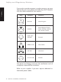
If you wish to use the computer in another country, you must
ensure that you use a power cord and plug which complies
with the safety standards of that country.
Plug
Standard
Countries
BS1363A
United Kingdom
SHUCO
Austria, Belgium, Finland,
France, Germany, Holland,
Italy, Norway, Sweden
250V
E
L
N
250V
E
N
L
250V
N
L
SRAF 1962/
DB16/87
Denmark
NEMA 5-15P
USA, Canada
ASE 1011
Switzerland
AS 3112-1981
Australia
E
125V
E
N
L
250V
250V
The power cord fittings must bear the certification mark of
the agency responsible for evaluation.
Refer to your supplier if you ever require additional or
alternative power cables.
II
LS PRO OWNER'S HANDBOOK
Safety and Regulatory Notices
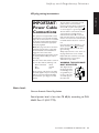
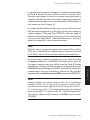
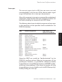
UK plug wiring instructions
This equipment is supplied with a mains
lead that has a non-removable moulded
plug. If the socket outlets are not suitable
for the plug supplied with this appliance,
it should be cut off and an appropriate
three-pin plug fitted.
Note: The plug severed from the mains
lead must be destroyed, as a plug with
the bared flexible cord is hazardous if
engaged in a live socket outlet.
The following wiring information should
be employed when adding the replacement plug.
The wires in the mains lead are coloured
in accordance with the following code:
Green and Yellow
Blue
Brown
Earth
Neutral
Live
As the colours of the wires in the mains
lead of this appliance may not correspond
with the coloured markings identifying
the terminals in your plug, proceed as
follows.
Safety
IMPORTANT:
Power Cable
Connections
The wire which is coloured green-andyellow must be connected to the
terminal in the plug which is marked with
the letter E, or by the earth symbol
or coloured green or green-and-yellow.
The wire which is coloured blue must be
connected to the terminal which is
marked with the letter N or coloured
black. The wire which is coloured brown
must be connected to the terminal which
is marked with the letter L or coloured
red.
Use a fuse approved to BS1362, i.e. one
or mark. Only
which carries the
replace the fuse with one of the same
type and rating.
ASA
Always replace the fuse cover, never use
the plug with the fuse cover omitted.
Replace with same colour fuse cover only.
Replacement fuse covers may be
obtained from your dealer.
WARNING: THIS APPLIANCE
MUST BE EARTHED
This diagram shows
the wiring inside the
moulded plug. Use it
as a guideline if you
need to re-fit a plug N
of a similar type to
the mains lead.
E
L
Noise levels
German Acoustic Noise Regulation
Sound power level is less than 70 dB(A) according to DIN
45635 Part 19 (ISO 7779).
LS PRO OWNER'S HANDBOOK
III
Safety and Regulatory Notices
Safety
Refer to the labels on the underside of the computer to establish which of the following warnings
apply.
FCC Class A
Warning - this equipment has been tested and found to comply with the limits for a Class A
computing device, pursuant to Subpart J of Part 15 of FCC rules. Only peripherals (computer
input/output devices, terminals, printer, etc.) certified to comply with the Class A limits may be
attached to this computer. Operation of this equipment in a residential area may cause
unacceptable interference to radio and television reception requiring the operator to take
whatever steps are necessary to correct the interference.
FCC Class B
Warning - this equipment has been certified to comply with the limits for a Class B computing
device, pursuant to Subpart J of Part 15 of FCC rules. Only peripherals (computer input/output
devices, terminals, printer, etc.) certified to comply with the Class B limits may be attached to this
computer. Operation with non-certified peripherals is likely to result in interference with radio
and TV reception.
Radio and television interference
The computer described in this manual generates and uses radio frequency energy for its
operation. If it is not installed and used properly, in strict accordance with the manual, it may
cause interference with radio and television reception.
The computer has been tested and found to comply with the RF emission limits for an FCC Class
B computing device which is intended to provide reasonable protection against such interference
in a residential installation. However, there is no guarantee that interference will not occur in a
particular installation.
If this equipment does cause interference with radio or television reception, which can be
determined by turning the equipment off and on, the user is encouraged to try to correct the
interference by one or more of the following measures:
•
•
•
•
•
•
•
Move the computer away from the receiver being interfered with.
Turn the computer with respect to the receiver.
Turn the receiver with respect to the computer.
Plug the computer into an outlet that is on a different branch circuit from the receiver.
Disconnect and remove any I/O cables that are not being used.
Unplug and remove any expansion cards that are not being used, and replace the relevant
blanking plates.
Make sure that the computer is plugged into a grounded outlet.
If you need additional help, consult your supplier. You may find the following booklet helpful: How
to Identify and Resolve Radio-TV Interference Problems. This booklet is available from the US
Government Printing Office: Washington DC 20402 - Stock No. 004-000-000345-4.
DOC Class A
The computer described in this manual complies with: Canadian DOC radio interference
regulations CRCc 1374 governing Class A digital devices.
DOC Class B
The computer described in this manual complies with: Canadian DOC radio interference
regulations CRCc 1374 governing Class B digital devices.
IV
LS PRO OWNER'S HANDBOOK
CONTENTS
apricot
Chapter
Contents
CONTENTS
1
Introducing…
Summary of features 1/1
Unpacking 1/3
Pictorial guide 1/6
Contents
2
Getting Started
General advice 2/1
Connecting the components 2/2
Turning on and booting the computer 2/4
Backing up pre-installed software 2/9
Using the 3.5" diskette drive 2/10
Using the BIOS Setup utility 2/12
Using Apricot Help 2/13
3
Using the BIOS Setup Utility
Accessing BIOS Setup 3/1
Using BIOS Setup dialogs 3/2
Basic configuration options 3/4
Advanced configuration options 3/9
4
Networking
What is Integrated Network Architecture? 4/1
Finding out about your network 4/2
Selecting thick- or thin-Ethernet 4/3
Connecting Ethernet cables 4/3
5
Using the Audio System
Connecting audio devices and controlling output volume 5/1
Using the audio system under Microsoft Windows 5/4
Using the audio system under MS-DOS 5/4
LS PRO OWNER'S HANDBOOK
I
Contents
Contents
6
Using the Security System
Features of the security system 6/1
Configuring the security system 6/4
Setting up a security configuration 6/6
Defining user accounts 6/9
Understanding the logon sequence 6/14
Changing a password at logon 6/17
Unattended mode for Microsoft Windows 6/18
Telling users about the security system 6/19
7
Using PCMCIA Cards
What is PCMCIA? 7/1
Installing PCMCIA cards 7/2
Inserting and removing PCMCIA cards 7/2
Configuring PCMCIA cards 7/4
8
Maintaining and Transporting
Cleaning the computer 8/1
Recharging the configuration battery 8/3
Transporting the computer 8/4
Using the computer in another country 8/4
9
Upgrading
Adding more memory 9/2
Upgrading the processor 9/5
Adding an external cache 9/9
Adding a diskette drive 9/10
Adding a hard disk drive 9/13
Adding both drives at once 9/15
A
Inside the System Unit
Anti-static precautions A/1
Opening the system unit A/2
Changing jumper settings A/3
II
LS PRO OWNER'S HANDBOOK
Contents
B
Technical Information
Specifications B/1
Physical characteristics B/2
Electrical characteristics B/2
Port characteristics B/3
System resources B/8
C
Quick Guide To Security
Contents
LS PRO OWNER'S HANDBOOK
III
INTRODUCING...
apricot
Chapter
Chapter
1
Introducing
1
INTRODUCING
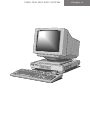
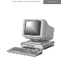
This chapter gives you a quick tour of your Apricot LS Pro
computer. The initial summary of features is intended mostly
for people who know a bit about computers and want to get
an idea of what this one can do. But the unpacking instructions
and pictorial guide will be helpful to everyone.
Don’t worry if you’re unfamiliar with some of the computer
terminology used in this chapter. It’s provided simply as a useful
“shorthand” for more experienced readers. Be assured, you
don’t need to understand any jargon to use the Apricot LS
Pro safely and efficiently. (On the other hand, it can’t hurt to
learn; introductory books about computers can be found in
your local bookshop or library.)
Summary of features
Standard features
The standard features of the Apricot LS Pro range include:
• Intel486 or IntelDX4 system processor with Pentium
OverDrive upgrade capability.
• 4 Mbytes of motherboard memory, upgradable to 64
Mbytes by the use of standard SIMMs (single in-line
memory modules).
• Graphical BIOS Setup configuration utility in read-only
memory (ROM).
• Cirrus Logic CL-GD543x/VL VESA local bus Enhanced
Video Graphics Array (EVGA) controller with at least
1 Mbyte of video memory.
LS PRO OWNER'S HANDBOOK 1/1
Chapter 1
Warning
Read the separate Power Connection Guide before using the
computer for the first time.
Introducing
• Integrated Network Architecture (INA): Advanced
TM
Micro Devices PCnet-32 VESA local bus Ethernet
adapter with ports for thick, thin and twisted-pair
Ethernet, and RPL (Remote Program Load) support in
BIOS.
• Enhanced Business Audio system: based on a Crystal
Semiconductor CS4231 chipset (featuring 16-bit digital
audio, stereo analog mixer and an Ad Lib-compatible
FM synthesizer), with stereo input/output sockets and
master volume control.
• Apricot LOC Technology v2.0 proprietary ROM-based
TM
on-board security system.
• PCMCIA module with Type II and Type III PC Card
sockets. Supports “Plug and Play” (PnP) interface.
Chapter 1
• Integrated Drive Electronics (IDE) disk drive system
(various capacities) and a 1.44 Mbyte 3.5" diskette drive
(optional).
• Parallel port with standard or ECP/EPP (Extended
Capabilities Port/Enhanced Parallel Port) functionality;
dual-channel serial port; extended keyboard; twobutton mouse.
Energy-efficient features
Most models in the range comply with the requirements of
the US Environmental Protection Agency’s “Energy Star”
programme for energy-efficient computers. These models
support:
• System Management Mode (SMM) of Intel SL Enhanced
processors.
• VESA BIOS Extensions for Power Management (VBE/
PM), for use with energy-efficient monitors that support
Display Power Management Signalling (DPMS).
Models fitted with very-high-capacity hard disk drives may be
unable to comply with Energy Star. Ask your supplier for more
information.
1/2
LS PRO OWNER'S HANDBOOK
Introducing
Advanced features
The following advanced features are available on some models
in the range:
• 256 Kbyte external (second-level) memory cache.
• 2 Mbytes of video memory (offering, for example,
800x600 resolution in 24-bit or ñtrueî colour).
Unpacking
On unpacking the computer, you should find:
• Apricot LS Pro system unit.
• Apricot/Mitsubishi monitor and accompanying UserÍs
Guide.
mono microphone.
• System unit AC power cord and monitor power cord
appropriate for the country of sale.
• System documentation (this OwnerÍs Handbook, etc.)
• Microsoft MS-DOS pack.
• Microsoft Windows for Workgroups pack (if the system
has a hard disk).
More elaborate systems may include software or hardware
options with accompanying installation diskettes and additional
documentation. Some of these options may have been factoryconfigured or installed by your supplier.
Keep the cartons, boxes and packaging materials; you will need
them again if you have to transport the computer elsewhere.
Make a note of the manufacturerÍs data recorded on the
various components (product codes, serial numbers, etc.). A
service engineer may need this information if the computer
develops a fault.
LS PRO OWNER'S HANDBOOK 1/3
Chapter 1
• Apricot extended keyboard, two-button mouse and
Introducing
1
2
3
4
5
apricot
Chapter 1
6
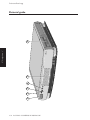
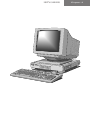
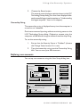
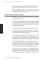
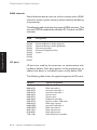
Pictorial guide
1/4
LS PRO OWNER'S HANDBOOK
Introducing
1
POWER button: press to turn the system on or off.
2
power indicator:
powered.
3
infrared sensor: detects the coded signals produced
by a KeyLOC card (an optional hand-held infrared
device that can be used with the security system).
4
activity indicators, from left to right:
lights when the system unit is
lights when the diskette drive is in use
lights when the hard disk is in use (depending on
the operating system)
lights when the computer accesses the network
(depending on the network software)
speaker grille.
6
3.5" diskette drive (optional).
There are air vents along the front and right-hand sides of
the system unit; do not block these vents or the system will
overheat.
LS PRO OWNER'S HANDBOOK 1/5
Chapter 1
5
1/6
LS PRO OWNER'S HANDBOOK
4
5 6
7
10101
1 2
PCMCIA
3
8
2
1
9
10 12
IEEE
802.3
11
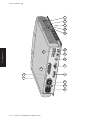
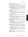
Chapter 1
13 14 15 16 17
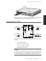
Introducing
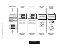
Introducing
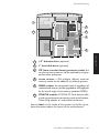
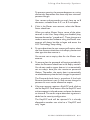
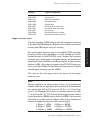
security loop: you can put a padlock through this
loop to secure the top cover.
2
handle: to remove the top cover, remove the retaining
screws at each side, then grasp and pull this handle firmly.
3
PCMCIA slots: suitable for all types of Personal
Computer Memory Card International Association
(PCMCIA) PC Card devices.
4
AC power outlet: where the monitor power cord
can plug in.
5
voltage selection switch: the system unit can be
set to operate with a 100-120 volt or 220-240 volt
AC power supply.
6
AC power inlet: where the system unit power cord
plugs in.
7
dual-channel serial port (50 baud to 19,200 baud):
typically used for connecting an external modem or
a serial printer signal cable.
8
parallel port: typically used for a printer signal cable.
9
monitor port: connect the monitor signal cable to
this port.
10 TPE Ethernet port: connect a cable with an RJ-45
connector to this port, to link the computer into a
twisted-pair Ethernet (10Base-T) network.
11 AUI Ethernet port (optional): connect an
attachment unit interface transceiver “drop” cable to
this port, to link the computer into a thick-Ethernet
(10Base-5) network.
12 BNC Ethernet port: connect a BNC T-connector
to this port, to link the computer into a thin-Ethernet
(10Base-2) network.
13 mouse port: connect the mouse to this port.
14 keyboard port: connect the keyboard to this port.
LS PRO OWNER'S HANDBOOK 1/7
Chapter 1
1
Introducing
15 audio input socket: allows you to connect a
microphone, a personal stereo (tape or CD), or a stereo
line-in signal from a high-fidelity tape deck or CD player,
to be used as a recording or monitoring source.
16 audio output socket: allows you to connect a
stereo headset or a pair of self-powered speakers.
Alternatively, it can provide a stereo line-out signal
to a high-fidelity amplifier or tape deck.
Chapter 1
17 volume control: a rotary control that adjusts the
volume of sound through the internal speaker and the
audio output socket.
1/8
LS PRO OWNER'S HANDBOOK
Introducing
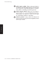
1
3
2
4
5
6
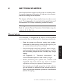
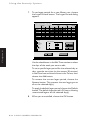
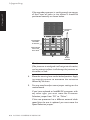
3.5" diskette drive (optional).
2
1" hard disk drive (optional).
3
ZIF (zero insertion force) processor socket: the
current system processor can be replaced by a higher
performance processor.
4
cache socket: a 256 kilobyte (Kbyte) external
memory cache can be added if not already present.
5
SIMM sockets: the computerÍs base 4 megabytes of
motherboard memory can be upgraded to 64 megabytes
by the use of single in-line memory modules (SIMMs).
6
PCMCIA module: PCMCIA PC Card devices offer
a wide range of expansion options such as fax/modem,
Token-Ring adapter or removable hard drives.
See the label on the inside of the system unit lid for up-todate information about the layout of the motherboard.
LS PRO OWNER'S HANDBOOK 1/9
Chapter 1
1
GETTING STARTED
apricot
Chapter
Chapter
2
Getting Started
2
GETTING STARTED
You should read this chapter even if you do not read any other.
It provides important information to help you site, connect,
power and configure the computer.
This chapter will tell you all you need to know in order to start
work. The chapters after this one deal with the special features of
the computer: BIOS Setup, networking, audio and security.
Warning
Read the separate Power Connection Guide before using the
computer for the first time.
General advice
This computer is designed to be used in a normal office
environment. Here are a few hints for choosing a suitable site:
• Place the system unit flat on a sturdy, level surface.
Remember to allow enough room on the right for you
to use the diskette drive, if one is fitted.
and extremes of heat and cold. Avoid situations in which
the surrounding temperature or humidity may change
rapidly.
See Appendix B, “Technical Information”, for
recommended temperature and humidity ranges.
• When positioning the system unit, monitor and
keyboard, take into account any local or national
regulations relating to ergonomic requirements.
For example, you should ensure that as little ambient
light as possible is reflected off the monitor screen as
glare, and that the keyboard is placed in a comfortable
position for typing.
LS PRO OWNER'S HANDBOOK 2/1
Chapter 2
• Site the computer away from moisture, direct sunlight,
Getting Started
• Give the computer plenty of room so that air can
circulate on all sides. Air is drawn into the system unit
through the vent under the front bezel and expelled
through a vent on the right-hand side. Ensure that these
vents are never obstructed.
• Do not allow any cables, particularly power cords, to
trail across the floor where they can be snagged by people
walking past.
Warning
The computer uses the system unit AC power cord as its “disconnect
device”. Ensure that the system unit is positioned close to the AC
power outlet, and that the plug is easily accessible.
To prevent fire and electric shock, do not expose any part of the
computer to rain or moisture.
Connecting the components
Chapter 2
See Chapter 1, “Introducing...”, if you need help identifying the
various ports on the system unit.
Checking the AC power supply
When your computer is delivered, it is ready for the commercial
AC power supply generally available in the country in which it
is first sold. It has been set for the correct voltage range, and
is supplied with an AC power cord and plug which comply with
the relevant safety standards.
Before using the computer in a country other than that in which
it was originally sold, you must discover the voltage and frequency
of that country’s AC power supply, and the type of power cord
required there. Check the power rating labels on the rear of
the computer’s system unit and its monitor to ensure that they
are compatible with the AC power supply.
If necessary, the AC voltage setting of the system unit can be
adjusted by the voltage selection switch on the rear of the
system unit. Refer to Chapter 8, “Maintaining and
2/2
LS PRO OWNER'S HANDBOOK
Getting Started
Transporting”, for instructions on how to do this. It is likely
that the monitor’s voltage setting will also need adjusting;
consult the User’s Guide that accompanies the monitor, or ask
your supplier for help.
The “Safety and Regulatory Notices” section at the start of this
Owner’s Handbook includes advice about suitable power cords.
Installing add-on options
If your computer arrived with uninstalled add-on options, (such
memory modules) consult Chapter 9, “Upgrading”, for stepby-step instructions for installing them. Some items may have
their own documentation that supplements or overrides the
instructions in this manual.
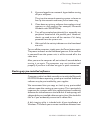
Connecting the components
Having assured yourself that the voltage settings and the AC
power cords of the computer, the monitor and any other
peripherals are correct, use the procedure below to connect
these components together. It is important that you take each
step the in order indicated.
If your AC power outlets have switches, set them to
their Off positions.
2.
Ensure that the system unit, the monitor, and any
peripherals are turned off.
3.
Connect the monitor signal cable between the monitor
and the monitor port on the rear of the system unit.
If the monitor signal cable is connected after the
computer is turned on, the display may appear in
monochrome (or not at all).
4.
Where appropriate, connect other signal cables between
your peripherals and their respective ports on the system
unit. Make sure the signal cables are connected securely.
5.
Plug the keyboard cable into the keyboard port on the
system unit. Be careful not to plug it into the mouse
port by mistake.
LS PRO OWNER'S HANDBOOK 2/3
Chapter 2
1.
Getting Started
6.
Plug the mouse into the mouse port on the system unit.
Never connect either the keyboard or the mouse while
the system unit is turned on.
7.
Where appropriate, connect the computer to the
network. See Chapter 4, “Networking”, for guidance
on connecting the computer to Ethernet networks.
8.
Connect the monitor power cord between the monitor
and the AC power outlet on the rear of the system unit.
9.
Connect the system unit power cord between the AC
power inlet on the rear of the system unit and a nearby,
grounded AC power outlet.
10. Where appropriate, connect power cords between your
peripherals and nearby, grounded AC power outlets.
11. If your AC power outlets have switches, set them to
their On positions.
The computer is now ready to use. The rest of this chapter
tells you how to turn the computer on and off, and how to
configure it using the BIOS Setup utility.
Chapter 2
Turning on and booting the computer
Turning the power on
To turn on the computer, simply press the POWER button. The
green indicator next to the POWER button lights to show that the
system unit is powered. Remember that the monitor has its own
power control; see the monitor’s User’s Guide for details.
If the computer does not start when the POWER button is
pressed, check that the system unit and monitor power cords
are securely connected and that the AC power supply is
switched on.
In the United Kingdom, and some other countries, AC plugs
contain fuses. If the fuse in the system unit’s AC plug blows
when you turn it on, this may be caused by an AC power surge,
2/4
LS PRO OWNER'S HANDBOOK
Getting Started
but is more often a symptom of problems with the computer
or its peripherals. Follow these steps:
1.
Turn off the computer and unplug all power cords.
2.
Unplug all peripherals.
3.
Try to discover the cause of the fault. If none is
apparent, replace the blown fuse with one of the same
rating, reconnect the system unit power cord and try
to turn it on again.
4.
If the replacement fuse blows, call an authorized
maintainer.
If the replacement fuse does not blow, reconnect a
peripheral and turn it on. Repeat this step for each
peripheral in turn.
Caution
Always make sure that the system unit is turned on before turning
on any attached peripherals, particularly a printer attached to the
parallel port. The parallel port is vulnerable to surges in the AC power
supply which may be passed on by the printer’s signal cable.
Power-on self-test
A configuration discrepancy might arise if you have just installed
or removed a hardware option (for example, if you have added
or replaced a SIMM). In this case the BIOS Setup utility is started
automatically.
LS PRO OWNER'S HANDBOOK 2/5
Chapter 2
Whenever the computer is turned on, the power-on self-test
(POST) routine tests various hardware components, including
memory, and compares the actual configuration of the
computer with that recorded in its memory. During this time,
various sign-on and POST messages are displayed, and you have
the opportunity of invoking the BIOS Setup utility to reconfigure
the computer (described later in this chapter). The appearance
of the screen during POST depends on whether you have
chosen the Text or Graphics startup option with BIOS Setup.
Getting Started
If POST detects a hardware fault, one or more error messages
are displayed. You may also be prompted to “Press the F1 key
to continue.” Your first action should be to turn off the
computer, wait at least 30 seconds, and then turn it on again
to see if the error is transient or persistent. Persistent POST
errors may indicate a fault in your system. If you press F1, the
computer attempts to continue despite the error indication
(for example, if a memory chip fails POST, the computer can
continue with less memory). If the problem persists, make a
note of the error messages, and consult your supplier or
authorized maintainer.
Beep codes
The computer uses special audio beep codes to signal certain
hardware faults. If you hear a beep code which is not
accompanied by a POST error message, call your supplier or
authorized maintainer.
The boot sequence
Chapter 2
Provided that POST succeeds without discovering any serious
errors or configuration discrepancies, the computer attempts
to find an operating system; that is, it attempts to boot. There
are three possibilities it may try: a system diskette, a bootable
hard disk partition, or remote booting.
System diskette
A system diskette is a diskette bearing at least the rudiments of an
operating system. If the computer finds such a diskette in the
diskette drive, it will boot from it. If it finds a non-system diskette,
the computer invites you to replace it and press the F1 key.
The BIOS Setup utility can be used to disable booting from a
system diskette.
Hard disk partition
The computer will try its hard disk if it can’t find a system
diskette. A hard disk may contain more than one bootable
2/6
LS PRO OWNER'S HANDBOOK
Getting Started
partition, for different operating systems, but only one of these
can be active at any one time. The computer loads its operating
system from the currently active partition.
Computers with a hard disk normally arrive with the Microsoft
MS-DOS/Windows operating system already in place or preinstalled.
If necessary, your operating system manuals should tell you how
to format a blank diskette as a system diskette or how to
partition and format a hard disk.
Caution
Partitioning or formatting a hard disk erases all the programs and
data recorded on that disk. Always make a backup copy of the
contents of the hard disk before you start.
Remote booting
Remote or network booting means that the computer loads
its operating system from a server elsewhere on the network.
The computer has a built-in ability to do this, by virtue of the
Remote Program Load (RPL) code in its BIOS ROM.
Remote booting won’t work unless there’s a RPL server
somewhere in your network. Don’t attempt to boot your
computer in this way without first checking with the network
administrator.
LS PRO OWNER'S HANDBOOK 2/7
Chapter 2
You have to enable RPL (pronounced “ripple”) with the BIOS
Setup utility. If your computer has a diskette or hard disk drive,
you will be asked each time the computer boots whether or
not you want to boot remotely this time.
Getting Started
Chapter 2
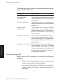
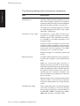
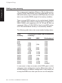
The following table lists some of the messages that might appear
during the boot sequence.
Message
Explanation
Non-system disk
or disk error
The diskette drive contains a non-system
diskette. Replace it with a system diskette
and press F1.
Diskette read failure
The diskette is either not formatted or
defective. Replace it with a system diskette
and press F1.
No boot sector
on fixed disk
The hard disk has no active, bootable
partition or is not formatted. Insert a
system diskette, press F1, and format the
hard disk as described in your operating
system manuals.
Fixed disk read failure
The hard disk may be defective. Press F1
to retry. If the problem persists, insert a
system diskette, press F1, back-up the data
held on the defective hard disk and try
reformatting it.
No boot device available This may indicate a fault in the diskette or
hard disk drive, or perhaps a damaged
system diskette. Press F1 to retry, using
another system diskette if possible. If the
problem persists, consult your supplier or
an authorized maintainer.
Turning the power off
Before turning off the computer, run through the following
checklist:
1.
Quit or exit from the applications you are running; be
sure to save any files you have altered.
Any unsaved information still held in the computer’s
system memory will be lost when you turn off the
computer.
2/8
LS PRO OWNER'S HANDBOOK
Getting Started
2.
If you are logged-in to a network, logout before turning
off your computer.
This gives the network operating system a chance to
free up the network resources you’ve been using.
3.
Close down or quit any software that employs virtual
memory or disk-caching (for example, Microsoft
Windows with SMARTDrive).
4.
Turn off any attached peripherals first, especially any
peripheral attached to the parallel port. However,
there’s no need to turn off the monitor if it’s being
powered from the system unit.
5.
Wait until all the activity indicators on the front bezel
are unlit.
To turn off the computer, simply press the POWER button again.
The power indicator on the front bezel goes out. If the monitor
is powered from the system unit, it will be turned off at the
same time.
After you turn the computer off, wait at least 5 seconds before
turning it on again. The computer may not initialize itself
properly if you turn it off then on again in quick succession.
Computers with a hard disk normally arrive with the Microsoft
MS-DOS/Windows operating system pre-installed. Additional
software may be pre-installed by your supplier.
We recommend that you copy or back up any pre-installed
software soon after setting up your system. This is particularly
important for systems which are supplied without installation
diskettes for the software on the hard disk. A backup copy will
safeguard the pre-installed software against loss if the hard disk
fails or if you accidentally overwrite or delete files.
A disk imaging utility is included with all pre-installations of
Windows. This allows you to create installation diskettes from
LS PRO OWNER'S HANDBOOK 2/9
Chapter 2
Backing-up pre-installed software
Getting Started
disk images present on the hard disk. Once you have done this,
you can delete the disk images from your hard disk. See the
utility’s on-line help for more information.
To back up other pre-installed software, use Backup for DOS
or Backup for Windows as described in your MS-DOS manual.
It is a good idea to begin by creating a bootable system diskette
containing the programs needed to partition and format the
hard disk and to restore the backed up copy. In this way, you
should be able to recover any programs or data lost by a hard
disk failure.
Note
Any copy you make of pre-installed software must be used only as
a backup copy, in case the pre-installed version is lost or needs reinstalling or reconfiguring. In particular, you are not allowed to use
installation diskettes created from disk images to install the software
onto another computer.
Using the 3.5" diskette drive
Chapter 2
The (optional) 3.5" diskette drive can read and write doublesided diskettes with a formatted capacity of either 1.44 Mbytes
(if marked “HD” or “high density”) or 720 Kbytes (if marked
“DD” or “double density”).
Each diskette has a rigid plastic cover with a metal shutter that
guards the disk surface. The drive automatically moves the
shutter aside to read the diskette. Never touch the exposed
surface under the shutter; you could deform the disk or leave
a fingerprint that might make the diskette difficult to read.
Keep diskettes well away from dust, moisture, magnetic objects,
and equipment that generates magnetic fields. Also, avoid
extremes of temperature and exposure to direct sunlight.
Otherwise, data recorded on the diskette may become
corrupted.
2/10
LS PRO OWNER'S HANDBOOK
Getting Started
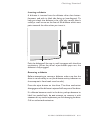
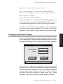
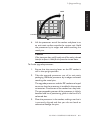
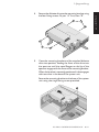
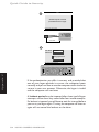
Inserting a diskette
A diskette is inserted into the diskette drive slot shutterforemost, and with its label side facing up (see diagram). To
help you check the diskette is the right way round, there’s
usually a small arrow on the face of the diskette which must
point towards the drive when you insert it.
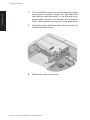
Removing a diskette
Before attempting to remove a diskette, make sure that the
drive is not currently in use (the diskette activity indicator on
the computer’s front bezel must be unlit).
Press the eject button on the drive. The drive mechanism
disengages and the diskette is ejected half-way out of the drive.
If a diskette becomes stuck in the drive, perhaps because its
label has peeled back, do not attempt to remove it with
tweezers or any similar implement; you risk damaging the drive.
Call an authorized maintainer.
LS PRO OWNER'S HANDBOOK
2/11
Chapter 2
Push the diskette all the way in until it engages with the drive
mechanism. When the drive's eject button pops out, the
diskette is fully engaged.
Getting Started
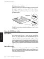
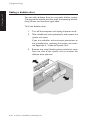
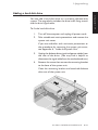
Write-protecting a diskette
A diskette can be write-protected by sliding a small tab towards
the edge of the diskette to expose the little hole beneath it
(see diagram). With the tab in this position, you can read, copy
or print files from the diskette, but you cannot create, rename
or delete any files.
PROTECTED
UNPROTECTED
The BIOS Setup utility can disable the diskette drive, or make
it read-only.
Chapter 2
Using the BIOS Setup utility
What is BIOS?
BIOS (pronounced “bye-oss”) stands for basic input/output
system. The BIOS operates at the boundary between the
computer’s hardware (the system processor, memory, diskette
and hard disk drives, and so on) and its software (the operating
system and applications), and effectively mediates between the
two. The BIOS is permanently encoded in an area of read-only
memory (ROM), although it can be modified if necessary by an
authorized maintainer.
What is BIOS Setup?
BIOS Setup is a utility programmed into the computer’s BIOS
ROM. Its main purpose is to allow you to view and alter your
computer’s configuration. BIOS Setup is also used to configure
the on-board security system.
2/12
LS PRO OWNER'S HANDBOOK
Getting Started
To configure (set up) a computer means to declare or describe
its hardware components and to say how you want them to
behave. Configuring your computer is necessary to ensure that
the software you use can recognise and exploit the hardware’s
capabilities.
A record of the current configuration is kept in a special part of
the computer’s memory, known as CMOS memory. This type of
memory is easily sustained by a small battery, so that its contents
can be preserved while the computer is turned off.
Your computer arrives already configured, but may need to be
configured again if you add upgrades such as memory modules
or an external memory cache.
Accessing BIOS Setup
BIOS Setup can be invoked whenever you turn on or reboot
your computer, by pressing the ALT+S key combination (text
startup) or choosing the Setup button (graphics startup) during
the initial power-on self-test (POST) routine.
To prevent unauthorized reconfiguration, the security system
can disable access to BIOS Setup for individual users.
Using Apricot Help
Along with the diskettes provided with your computer, or the
software pre-installed on its hard disk, you will often find one
or more Apricot Help files. These will explain any special
features of the system, and tell you how to install the software
needed to exploit those features.
LS PRO OWNER'S HANDBOOK
2/13
Chapter 2
For more information, see Chapter 3, “Using the BIOS Setup
Utility”, and Chapter 6, “Using the Security System”.
Getting Started
For example, the files provided with the Apricot LS Pro include
help on:
•
•
•
•
Cirrus Logic CL-GD543x EVGA video drivers
AMD PCnet-32 network drivers
CrystalWare audio driver and utilities
The Energy Star Programme
Apricot Help may be supplied in various forms, depending on
the intended operating system; for the Microsoft MS-DOS/
Windows operating system they are usually Windows help files
or ASCII text files.
Viewing Windows help files
Windows help files can be displayed only by the Microsoft
Windows Help program (v3.1 or later). Windows help files
may be identified by their .HLP file extensions, although this is
not an infallible guide as some other help formats also use the
.HLP extension. They are often accompanied by .ICO icon files
of the same name.
Chapter 2
If your computer has a hard disk on which Apricot has preinstalled Microsoft Windows, copies of some Windows help
files may already be available as icons in the “Apricot” program
group. To view the help file simply double-click on its icon, or
select the icon and press ENTER. For more information about
using Help, see your Windows documentation.
If the Windows help file you want to view is not already installed,
or if for any other reason you need to view a Windows help
file directly from a diskette:
2/14
1.
Insert the diskette into a suitable drive.
2.
Use Windows File Manager to view the contents of
the diskette.
LS PRO OWNER'S HANDBOOK
Getting Started
3.
Choose the .HLP help file you want either by doubleclicking on its filename or by selecting the filename with
the cursor and then pressing ENTER.
The Windows Help program starts, displaying the first
topic in the help file.
Alternatively, you can copy the Windows help file from the
diskette to a hard disk or network drive, and create a program
item for it using Program Manager. The help file can then be
viewed at any time simply by double-clicking on its icon. To do
this:
Insert the diskette into a suitable drive. Copy the .HLP
help file, and its associated .ICO icon file if it has one,
from the diskette to a hard disk or network drive.
2.
Choose New from the File menu in Program Manager.
Select the Program Item option in the New Program
Object dialog box, then choose OK. The Program Item
Properties dialog box appears.
3.
In the Description text box, type a suitable title for
the help file.
4.
In the Command Line text box, type the path and
filename of the help file (including its .HLP extension).
Alternatively, choose the Browse button, find the help
file, and choose OK.
Skip the next step if the help file doesn’t have an
associated icon file.
5.
Choose Change Icon. The Change Icon dialog box
appears. In the File Name text box, type the path and
filename of the .ICO file. Choose OK.
6.
In the Program Item Properties dialog box, choose OK.
LS PRO OWNER'S HANDBOOK
2/15
Chapter 2
1.
Getting Started
Viewing text files
ASCII text files, identified by their .TXT file extensions, can be
read by most text editors and wordprocessing programs.
Alternatively they can be displayed, one screenful at a time,
using the DOS commands type and more; for example:
type helpfile.txt | more
Version numbers
Chapter 2
All the help files provided by Apricot have a version number
so you can tell whether you’re looking at the most up-to-date
version. You can discover the version number of a Windows
help file by viewing it with Help and choosing About Help from
the Help menu.
2/16
LS PRO OWNER'S HANDBOOK
USING THE BIOS SETUP UTILITY
apricot
Chapter
Chapter
3
Using the BIOS Setup utility
3
USING THE BIOS SETUP
UTILITY
BIOS Setup is a utility programmed into the computer’s readonly memory (ROM). Its main purpose is to allow you to view
and alter the computer’s hardware configuration. It is also used
to configure the on-board security system. The current
configuration is kept in a special area of memory, called CMOS
memory, and maintained by a small battery. BIOS Setup can be
accessed whenever the computer is turned on or rebooted.
This chapter describes how to access and use BIOS Setup, with
the exception of the security system functions. For information
on configuring the security system, see Chapter 6, “Using the
Security System”.
Accessing BIOS Setup
To prevent unauthorized reconfiguration, the security system
can disable access to BIOS Setup for individual users.
To access the BIOS Setup utility:
1.
Turn on or reboot the computer (for example, press
CTRL+ALT+DEL in MS-DOS).
2.
If the security system is enabled, logon to the computer
using an account that includes the right to access the
BIOS Setup utility.
3.
In text mode, press the ALT+S key combination when
invited to do so. In graphics mode, use the mouse to
click on the Setup button (or press ALT+S while the
button is displayed).
The main BIOS Setup dialog box appears once POST
is completed.
LS PRO OWNER'S HANDBOOK 3/1
Chapter 3
BIOS sign-on and hardware configuration messages are
displayed, either in text or graphics format according
to how the startup mode is currently configured.
Using the BIOS Setup utility
4.
Use the BIOS Setup dialog to set basic configuration
options. Choose the Advanced button to set advanced
configuration options. Choose the Security button to
configure the security system (see Chapter 6). The
Security button is greyed-out if your user account does
not include the right to access the LOC Technology
Setup dialog.
BIOS Setup’s dialog boxes look like Microsoft
Windows dialog boxes, and work in a similar way. You
can select and choose items with the mouse or the
keyboard.
5.
After you have made your changes, choose the Save
button in the main BIOS Setup dialog to save the new
configuration. Or choose the Cancel button to
abandon all the changes you have made while in BIOS
Setup.
If you have saved any changes, the computer will reboot
automatically when you exit BIOS Setup.
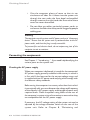
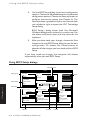
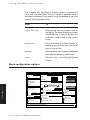
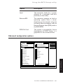
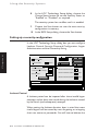
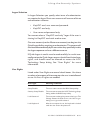
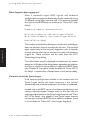
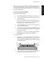
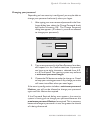
Using BIOS Setup dialogs
Information box
Setup
Option group
Hard Disk
Disk 1
LPS 525
Chapter 3
Option button
Check box
Memory
Save
Total
3712 KB
Cancel
None
Autodetect
User-defined
Disk 2
None
None
Autodetect
User-defined
User HDs...
Floppy Disk
3 '' 1.44M
None
3 '' 1.44M
Extended
3072 KB
Default
Power on sound
Low
High
Advanced...
Test
Enable
Enable ********
Boot Device
Monitor type
Local
Ethernet RPL
PCMCIA Card
SVGA
VGA/EVGA
EVGA (high refresh)
Enter user defined hard disk parameters
Help bar
3/2
LS PRO OWNER'S HANDBOOK
Security...
Startup
Graphics
Text
Power on password
Scroll bar
Text box
Button
Using the BIOS Setup utility
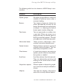
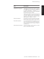
The following table lists the elements of BIOS Setup’s userinterface.
Description
Option groups
An option group collects a number of
related or exclusive items under a
common heading.
Buttons
You choose a button to initiate the
action described by the text on the
button. Some buttons are marked with
an ellipsis (...); choosing this kind of
button opens another dialog box.
Text boxes
You can type words or numbers into
a text box. When you move to an
empty text box, an insertion point (a
flashing vertical bar) appears. The text
you type starts at the insertion point.
Information boxes
These present information; their
contents cannot be altered by you.
Option buttons
Option buttons represent a group of
mutually exclusive options. You can
select only one option at a time.
Check boxes
A check box presents non-exclusive
options; you can select as many checkbox options as needed.
Scroll bars
Scroll bars behave like slide controls.
They are adjusted by pointing and
clicking on the scroll arrows at each
end of the bar.
Greyed-out options
When an option is dimmed or greyedout it cannot currently be selected or
chosen.
Help bar
The help bar displays information
about the currently-selected option.
LS PRO OWNER'S HANDBOOK 3/3
Chapter 3
Element
Using the BIOS Setup utility
The simplest way to select or choose items is to point and
click with a mouse. Note that the mouse is disabled while a
text box is selected. If you prefer using the keyboard, you can
use the following keystrokes:
Press
TAB
To
or SHIFT+TAB
Move to the next or previous item in
the dialog. To move directly to an item
hold down the ALT key and press the
character underlined in the item’s
name.
ARROW KEYS
Move between the items within an
option group. Also to move the scroll
box in a scroll bar.
SPACEBAR
Select or clear the currently-highlighted
item (option button or check box).
ENTER
Choose the currently-highlighted
button.
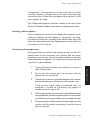
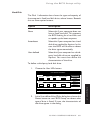
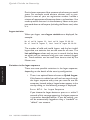
Basic configuration options
Setup
Hard Disk
Disk 1
LPS 525
Disk 2
None
None
Autodetect
User-defined
User HDs...
Floppy Disk
3 '' 1.44M
None
3 '' 1.44M
Extended
LS PRO OWNER'S HANDBOOK
3072 KB
Default
Power on sound
Low
High
Advanced...
Enable
Power on password
Enable ********
Monitor type
SVGA
VGA/EVGA
EVGA (high refresh)
Enter user defined hard disk parameters
3/4
Save
3712 KB
Cancel
None
Autodetect
User-defined
Chapter 3
Memory
Total
Test
Security...
Startup
Graphics
Text
Boot Device
Local
Ethernet RPL
PCMCIA Card
Using the BIOS Setup utility
Hard Disk
The Disk 1 information box shows the type and capacity of
the computer’s fixed hard disk drive, where known. Beneath
this are three option buttons:
Option
Description
None
Select this if your computer does not
have a fixed hard disk. This prevents
the BIOS looking for a hard disk, and
so speeds up the boot sequence.
Autodetect
Select this if your computer has a hard
disk drive supplied by Apricot. In this
case the BIOS will be able to detect
the drive type automatically.
User-defined
Select this if your computer has a thirdparty hard disk drive not supplied by
Apricot. You must then define the
characteristics of the drive.
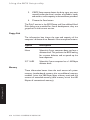
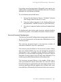
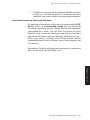
To define a third-party hard disk drive:
1.
Choose the User HDs button.
User defined hard disks
Heads
Sectors
097
10
17
Disk 2
Cylinders
Heads
Sectors
097
10
17
Capacity (MB)
0008
Capacity (MB)
0008
Save
Cancel
Detect 1
Detect 2
In the User-defined Hard Disks dialog box, choose the
Detect button to see if BIOS Setup can detect what
type of drive is fitted. If it can, the characteristics of
the drive appear in the dialog.
LS PRO OWNER'S HANDBOOK 3/5
Chapter 3
2.
Disk 1
Cylinders
Using the BIOS Setup utility
3.
If BIOS Setup cannot detect the drive type, you must
manually enter the drive’s number of cylinders, heads
and sectors, and its capacity, in the text boxes provided.
4.
Choose the Save button.
The Disk 2 entries in the BIOS Setup and User-defined Hard
Disk dialogs are provided for future development; they are
greyed-out in the current version.
Floppy Disk
The information box shows the type and capacity of the
computer’s diskette drive. Beneath it are two option buttons:
Option
Description
None
Select this if your computer does not have a
diskette drive. This prevents the BIOS looking
for a system diskette, and so speeds up the
boot sequence.
3.5" 1.44M
Select this if your computer has a 1.44 Mbyte
diskette drive.
Memory
Chapter 3
These information boxes show the total amount of system
memory (motherboard memory plus any additional memory
modules, minus the 384 Kbyte upper memory area) and the
amount of extended memory (total memory minus the 640
Kbytes of conventional memory).
3/6
LS PRO OWNER'S HANDBOOK
Using the BIOS Setup utility
Power-on Sound
When this option is enabled a tone will sound whenever the
computer is turned on.
To set the power-on sound:
1.
In the Power-on Sound group, select the Enable check
box.
2.
Choose the Test button to audition the power-on sound.
3.
Use the scroll bar to adjust the volume of the poweron sound as required.
Power-on Password
If this option is enabled a password must be entered every time
the computer is turned on.
To set a power-on password:
1.
In the Power-on Password group, select the Enable
check box.
2.
Select the text box, and type a password of up to seven
characters using A-Z and 0-9. The password is not
case-sensitive and cannot include space characters. To
preserve security, the password is not displayed as you
type but is shown as a string of asterisks.
The power-on password operates in addition to the security
system features, if enabled.
Monitor Type
It is important that you make the correct selection for your
monitor. Check the documentation that accompanies the
monitor to discover what resolutions and refresh rates (vertical
scan frequencies) it supports.
LS PRO OWNER'S HANDBOOK 3/7
Chapter 3
These three options alter the timings of the video signals
provided by the computer to suit a variety of different types of
monitor.
Using the BIOS Setup utility
Option
Resolution and refresh rates
SVGA
640x480 @ 60 Hz
800x600 @ 56 Hz
1024x768 @ 87 Hz Interlaced
VGA/EVGA
640x480 @ 60 Hz
800x600 @ 72 Hz
1024x768 @ 70 Hz
EVGA (high refresh)
640x480 @ 75 Hz
800x600 @ 75 Hz
1024x768 @ 75 Hz
1280x1024 @ 60 Hz
Startup
Chapter 3
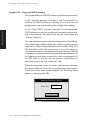
The Startup options control how the display looks during POST,
when BIOS sign-on and hardware configuration messages are
displayed.
Option
Description
Graphics
During POST, a dialog box is displayed giving
information about your computer, including
the BIOS version, type of video controller and
Ethernet node address. The dialog includes a
Setup button for accessing BIOS Setup.
Text
The same information is displayed, but using
only text. A message invites you to “Press
Alt+S for SETUP”.
Boot Device
These options allow you to select where you want the
computer to look for an operating system when it boots.
Remote or network booting using Ethernet RPL won’t work
unless there’s an RPL server somewhere in your network. Don’t
attempt to boot your computer in this way without first
checking with the network administrator.
3/8
LS PRO OWNER'S HANDBOOK
Using the BIOS Setup utility
Option
Description
Local
The computer looks for a system
diskette or a bootable hard disk
partition (in that order).
Ethernet RPL
The computer attempts to load an
operating system from a server
elsewhere on the network, using the
on-board Ethernet adapter and the
Remote Program Load (RPL) code in
the BIOS ROM.
PCMCIA Card
This option is provided for future
development of BIOS Setup; it is
greyed-out in the current version.
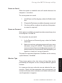
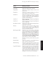
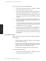
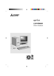
Advanced configuration options
Advanced
Parallel Port
Standard
EPP Compatible
ECP Compatible
Energy Conservation
Disable
CPU Power Management
Hard Disk Power Down
CPU Power Management
Floppy Disk
Keyboard
Floppy Write
Mouse
Floppy Boot
Parallel port
Parallel Port
Serial port
Serial Port 1
Hard Disk Controller
Serial Port 2
Ethernet
Hard Disk Controller
Floppy disk
Ethernet
PCMCIA
Save
Default
Cancel
BIOS Copy At 16MB
External Cache
BIOS Shadowing
Inactivity timer (min.) 5
Large HD Translation
Enhanced Parallel Port (EPP) Compatible
LS PRO OWNER'S HANDBOOK 3/9
Chapter 3
i486 Cache
Using the BIOS Setup utility
Parallel Port
These three options allow you to set the mode of the parallel
port.
Option
Description
Standard
Standard IBM AT-compatible bidirectional “Centronics” mode.
EPP Compatible
Compatible with the Enhanced Parallel
Port standard.
ECP Compatible
Compatible with the Microsoft/
Hewlett Packard Extended Capabilities
Port standard.
Disable
These check boxes allow you to disable various motherboard
features or components. Obviously, you should not do this unless
you are certain you will not need those features or components.
In particular, there is normally no reason to disable the internal
or external memory cache, as doing so severely degrades the
computer’s performance. Some old software which is speed
sensitive may not work with caching enabled, but this is very
unlikely nowadays.
Chapter 3
However, you might want to disable some features for security
reasons. For example, disabling the ability to boot from the
diskette drive can help prevent the introduction of computer
viruses into the system.
Occasionally, you may need to disable motherboard
components to free system resources for use by PCMCIA cards
(although in general the BIOS’s support for Plug and Play
PCMCIA should make this unnecessary).
More information about the computer’s use of interrupts, DMA
channels, memory and I/O ports is given in Appendix B,
“Technical Information”.
3/10
LS PRO OWNER'S HANDBOOK
Using the BIOS Setup utility
Option
Meaning if selected
Disables the diskette drive controller.
Disables the computer’s ability to write to the
diskette drive.
Floppy Boot
Disables the computer’s ability to boot from a
system diskette in the diskette drive.
Parallel Port
Disables the parallel port, freeing interrupt IRQ7
and I/O ports 3BCh-3BFh. However, IRQ7 can
usually be “double-booked” without affecting the
operation of the parallel port.
Serial Port 1
Disables serial port 1, freeing interrupt IRQ4 and
I/O ports 3F8h-3FFh.
Serial Port 2
Disables serial port 2, freeing interrupt IRQ3 and
I/O ports 2F8h-2FFh.
Hard Disk Controller
Disables the hard disk controller, freeing I/O ports
1F0h-1F8h and 3F6h-3F7h.
Ethernet
Disables the on-board network adapter, freeing
interrupt IRQ5 and I/O ports 300h-317h.
(However, interrupt IRQ5, even if free, cannot be
used by the PCMCIA interface.)
BIOS Copy At 16MB
Disables the “copy” of the computer’s BIOS ROM
which normally appears in the computer’s address
space just below 16 Mbytes (between FE0000h and
FFFFFFh). This is not a real copy, just the same
ROM addressed through a different (higher) set
of memory addresses. This copy must be disabled
if your computer actually has 16 Mbytes (or more)
system memory, or the two will conflict.
i486 Cache
Disables the memory cache inside the system
processor.
External Cache
Disables the external, or second-level memory
cache, outside the system processor.
BIOS Shadowing
Disables the scheme whereby the contents of the
computer’s BIOS ROM are copied into system
memory, where they can be accessed more quickly.
Large HD Translation
Disables the scheme (known as Extended CHS)
whereby the BIOS is able to access hard disk drives
of greater than 504 Mbytes capacity. You might
need to do this if your operating system does not
support Extended CHS, in which case the drive
will appear to have less than its full capacity.
LS PRO OWNER'S HANDBOOK
3/11
Chapter 3
Floppy Disk
Floppy Write
Using the BIOS Setup utility
Energy Conservation
These options control the computer’s power management
features. If you disable them, the computer’s system unit will
no longer be Energy Star compliant (although the monitor may
continue to comply).
Option
Meaning if selected
Hard Disk Power Down
Enables the feature that automatically spins down the hard disk
after 20 minutes of inactivity.
CPU Power Management Enables the feature that automatically slows down the system
processor during periods of
inactivity.
CPU Power Management
These options control the feature that automatically cuts the
system processor’s external clock speed down to around
8␣ MHz during periods of inactivity (to reduce power
consumption) and restores it to 25/33␣ MHz again when needed.
This option group is greyed-out if CPU Power Management is
disabled.
The check boxes allow you to select what events or activity
will wake the processor.
Chapter 3
In the Inactivity Timer text box, specify the period of inactivity
after which the system processor will be slowed down.
3/12
LS PRO OWNER'S HANDBOOK
NETWORKING
apricot
Chapter
Chapter
4
Networking
4
NETWORKING
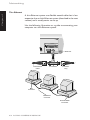
The physical network connection is only the first step in
establishing a networking environment; you will also need the
appropriate network software. Consult your network
documentation or the person (or department) responsible for
administering the network.
You must not attempt to connect your computer to the
network without first informing the network administration
or the other users of the network.
What is Integrated Network Architecture?
Integrated Network Architecture (INA) is Apricot’s term for
technology that makes it easier to connect your computer to
an Ethernet network. (“Ethernet” is the more common name
for the networking standard defined by the 802.3 Committee
of the Institute of Electrical and Electronics Engineers or IEEE.)
At the heart of INA is the Advanced Micro Devices’ PCnet-32
VESA local bus Ethernet adapter.
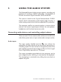
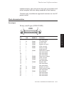
There are three network ports on the rear of the computer,
one for each of three alternative types of Ethernet cabling: thinEthernet (formally designated as 10Base-2), thick-Ethernet
(10Base-5) and twisted-pair Ethernet or TPE (10Base-T). You
can only use one port at a time, and must set a jumper inside
the computer accordingly.
Support for remote booting using the industry-standard
Remote Program Load (RPL) protocol is provided directly in
BIOS, so a separate remote boot ROM is not needed.
LS PRO OWNER'S HANDBOOK 4/1
Chapter 4
This chapter tells you how to physically connect your computer
to an Ethernet network.
Chapter 4
Networking
Apricot provides a comprehensive set of network drivers for
the PCnet adapter. For more information, view the Apricot
Help file that accompanies the drivers.
Finding out about your network
An Ethernet network may contain as few as two computers or
many hundreds. Obviously, the size and complexity of your
network will determine exactly how you should go about
making the connection to it.
If yours is a large or well-established network, you may find
that the network cabling has been laid in ducts under the floor,
or in the walls, of your workplace, and that suitable network
outlets have been provided nearby for you to plug into. There
may also be a network administrator (or possibly a network
administration department) whose job it to help new users
connect to the network.
On the other hand, if your network is small, the procedure
may be more informal. This is particularly likely to be the case
if you are running a peer-to-peer network. The network cabling
may be in plain view, and connection of your computer may
simply involve attaching, with the cooperation of your fellow
networkers, the correct cable to the correct Ethernet port.
So, before you connect your computer, you should find out
the answers to a few questions about your network:
1.
Is there a network administrator or network
administration department?
If there is, tell them that you want to add a new node
and ask for connection instructions. All but the smallest
networks require some form of network
administration, and any instructions you get from them
will always be more pertinent than the guidelines
contained in this manual.
4/2
LS PRO OWNER'S HANDBOOK
Networking
2.
You will need to ensure that the adapter is correctly
configured for your network.
3.
Is there a nearby network outlet you can plug
into, or must you must connect directly to the
network cabling?
Obviously a pre-installed network outlet makes your
task much easier. If you must connect directly to the
network cabling, you will have to keep in mind the
various technical limitations of your particular type of
Ethernet cabling.
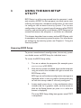
Selecting thick- or thin-Ethernet
If your network uses thick-Ethernet cabling, you may have to
change a jumper setting inside the computer, as it is usually set
to use thin-Ethernet. For more information, see the section
on “Changing jumper settings” in Appendix A, “Inside the
System Unit”.
Connecting Ethernet cables
Remember to find out if your network has a network
administrator or a network administration department, and if
so seek their prior authorization and assistance. Their
instructions will always be more pertinent than those provided
here.
Warning
Before connecting any network cables, turn off the computer and
unplug all power cords. Make sure that network is not in use; existing
network users should be logged off.
LS PRO OWNER'S HANDBOOK 4/3
Chapter 4
What type of cabling does your network use:
thin, thick or twisted pair?
Networking
Chapter 4
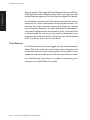
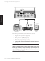
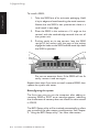
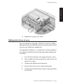
Thin Ethernet
A thin-Ethernet system uses flexible coaxial cable that is less
expensive than a thick-Ethernet system (described in the next
section) and is usually easier to set up.
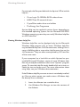
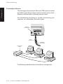
Use the following illustration as a guide to connecting your
computer to a thin-Ethernet system.
10 BASE-5
IEEE
802.3
10 BASE-T
10 BASE-2
BNC Port
Thin-Ethernet
Cable
T-Connector
Connector
Plug
BNC
Terminator
BNC Barrel
Connector
Grounded BNC
Terminator
4/4
LS PRO OWNER'S HANDBOOK
Networking
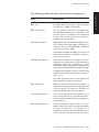
The following table describes the hardware components.
Description
BNC port
The BNC port on the back of the computer
connects it to a BNC T-connector.
BNC T-connector
The T-connector connects to the BNC port,
and thin-Ethernet cables are connected to the
crossbar of the T-connector. (For computers
at the ends of the network, a terminator
replaces one of the cables.)
Thin-Ethernet cable
High-quality thin coaxial cable (RG-58 A/U or
C/U), with a nominal impedance of 50 ohm, for
networks that use the IEEE 802.3 10Base-2
standard (e.g. Belden 9907).
A thin-Ethernet cable has BNC connectors at
each end, for connection to BNC T-connectors
or barrel connectors.
Thin-Ethernet segment
Thin-Ethernet cable can normally be used in
segments up to 185 metres long, and can have a
maximum of 30 nodes (computers or other
networked devices) per segment. Neighbouring
nodes must be separated by at least 50 cm of cable.
A segment must always be a line; however many
twists and turns it has it must never branch or
form a loop.
Up to five segments can be joined together by
signal repeaters, bridges and routers.
BNC terminator
When a computer is at the end of a segment, a
terminator must be connected to the open end
of the computer’s T-connector. Terminators
used with RG-58 cable must be 50 ohm.
Grounded terminator
It is recommended that the terminator at one
end of the network is a grounded terminator.
The grounded terminator has a grounding wire
connected to it.
BNC barrel connector
A barrel connector can be used to join two
pieces of Ethernet cable. Keeping the number
of barrel connections on a network to a
minimum increases network reliability. Do not
use T-connectors in place of barrel connectors.
LS PRO OWNER'S HANDBOOK 4/5
Chapter 4
Item
Networking
Chapter 4
Apricot supplies Thin-cable Ethernet Network Starter and Thincable Ethernet Node Addition packs which can help you build
simple Ethernet segments. Ask your Apricot supplier for details.
It is possible to remove the T-connector from the rear of your
computer for a short time without disrupting the network. For
example, you might remove it temporarily while you relocate
your computer. However, the open end of the T-connector is
a source of interference to the network signals, so do not leave
it disconnected for too long. If you have to disconnect your
computer from the network for a long time, you should replace
the T-connector with a barrel connector.
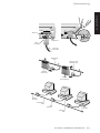
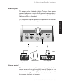
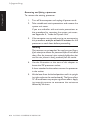
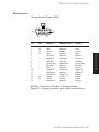
Thick Ethernet
A thick-Ethernet system uses rugged, heavily-insulated coaxial
cable. With thick cable, you can connect more computers and
the distance between them can be greater, but the cable is more
expensive and more difficult to install than thin-Ethernet cable.
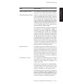
Use the following illustration as a guide to connecting your
computer to a thick-Ethernet system.
4/6
LS PRO OWNER'S HANDBOOK
Networking
Chapter 4
LOCKED
IEEE
802.3
10 BASE-5
OPEN
IEEE
802.3
10 BASE-5
Slide-Lock
10 BASE-T
10 BASE-2
10 BASE-T
10 BASE-2
AUI (DIX) Port
Male
Connector
Transceiver
"Drop" Cable
Thick Ethernet
Cable
Female Connector
(With Slide-Lock)
MAU With
Intrusive Tap
MAU With
Non-Intrusive Tap
N-Series
Terminator
Thick-Ethernet
Cable
MAU
Transceiver
N-Series
Terminator
Transceiver
Cable
LS PRO OWNER'S HANDBOOK 4/7
Networking
Chapter 4
The following table describes the hardware components.
Item
Description
AUI (DIX) port
The AUI or attachment unit interface port on the
back of the computer connects it to a length of
transceiver cable. The AUI port has a sliding latch
that locks the cable connector onto the port.
The AUI port is sometimes referred to as a DIX
port (after Digital, Intel and Xerox, the original
developers of Ethernet).
Transceiver “drop” cable
A transceiver or drop cable connects your
computer to an MAU transceiver on a thickEthernet system. (The thick-Ethernet cable is
too inflexible to be attached directly to the
computer itself.)
A male connector is located at one end of the
transceiver cable; this attaches to the computer.
A female connector (with slide-lock) is located
at the other end; this attaches to the MAU
transceiver (or to a network outlet).
Maximum length for a transceiver cable is 50
metres.
MAU transceiver
An MAU (media attachment unit) transceiver
connects the computer to the thick-Ethernet
cable.
MAUs are of two basic types: intrusive or
vampire tap, and non-intrusive or N-series tap.
An intrusive tap attaches by piercing the coaxial
cable; the advantage of this is that the cable can
be tapped at any convenient point. An nonintrusive tap can normally be installed only
where the cable is interrupted by an N-series
barrel connector.
MAU transceivers are sometimes hidden behind
network outlets. In this case the computer’s
transceiver cable attaches to a nearby network
outlet.
Thick-Ethernet cable
4/8
LS PRO OWNER'S HANDBOOK
Thick coaxial cable with a nominal impedance
of 50 ohm and marks at 2.5 metre intervals
where it can be tapped, for networks that use
the IEEE 802.3 10Base-5 standard (e.g. Belden
9880). Also known as “standard” cable.
Networking
Description
Thick-Ethernet segments
Thick-Ethernet cable can be used in segments
up to 500 metres long, and can have a maximum
of 100 transceivers connected to it.
Neighbouring transceivers must be separated
by at least 2.5 metres of cable.
Typically, a thick-Ethernet network is composed
of a main segment or spine, with additional
segments or ribs attached to the spine through
signal repeaters, bridges or routers.
N-series terminator
A terminator must be connected to the thickEthernet cable at each endpoint of the network.
Grounded terminator
It is recommended that the terminator at one
end of the network is a grounded terminator.
The grounded terminator has a grounding wire
connected to it.
N-series barrel connector
A barrel connector can be used to join two
pieces of thick-Ethernet cable.
LS PRO OWNER'S HANDBOOK 4/9
Chapter 4
Item
Networking
Chapter 4
Twisted-pair Ethernet
The advantages of twisted-pair Ethernet (TPE) systems are that
the cable is generally less expensive than systems such as thickEthernet, and the cable is relatively easy to install.
Use the following illustration as a guide to connecting your
computer to a twisted-pair Ethernet system.
TPE Port
(RJ-45 Socket)
IEEE
802.3
10 BASE-T
10 BASE-5
10 BASE-2
RJ-45
Connector
Twisted-Pair
Ethernet Cable
Concentrator
(HUB)
The following table describes the hardware components.
4/10
LS PRO OWNER'S HANDBOOK
Networking
Description
TPE port (RJ-45 socket)
The TPE port on the back of the computer
connects it to the twisted-pair Ethernet cable.
Twisted-pair Ethernet cable
Cable for a twisted-pair Ethernet system can be
either unshielded twisted-pair (UTP) or shielded
twisted-pair (STP). Both types of cable consist of
two or more pairs of twisted copper wires;
however, STP has a shielding layer of foil and
copper braid around the inner cable that protects
the wiring from electromagnetic interference or
“noise”. Shielded cable is more expensive, but
recommended (e.g. Belden 9855).
The cable should meet at least the minimum
requirements of the IEEE 802.3i 10Base-T
standard: it should be of 100 ohm impedance
for a 5-10 MHz signal, and 0.5 mm or 24 AWG
in diameter. 8-core untwisted and unshielded
cable (e.g. FCC-68) is generally unsuitable and
should only be used to connect the computer
to an RJ-45 wall socket less than 2 metres away.
Maximum cable length is 100 metres. If the path
includes more than four RJ-45 plug/socket
connections, reduce the maximum length by 15
metres for each additional connection. Do not
add connections by splicing the cable.
RJ-45 connector
An RJ-45 connector is located at each end of
the twisted-pair cable. To connect the cable to
the system unit, align the connector so the small
plastic tab is in line with the slot in the TPE port
(RJ-45 socket), and push in the connector until
you hear a click. (The connector is similar to
the plastic plug used to connect a telephone
cord to a wall outlet.)
Concentrator or hub
The computers in a TPE system are connected
to each other by using a concentrator or hub.
Cable from each computer is plugged into a
socket at the hub.
Hubs of various capacities are readily available,
from desktop models with connectors for only
a dozen computers to rack-mounted models
which can interface over a hundred nodes.
A small network can be built by connecting a
group of computers using a single hub. For a
larger network, twisted-pair cabling can be used
to connect hubs. For greater distances still, hubs
can be connected to an Ethernet segment.
LS PRO OWNER'S HANDBOOK
4/11
Chapter 4
Item
USING THE AUDIO SYSTEM
apricot
Chapter
Chapter
5
Using the Audio System
5
USING THE AUDIO SYSTEM
The Enhanced Business Audio system supports recording and
playback of waveform (WAV) audio files, and playback of
Musical Instrument Digital Interface (MIDI) audio files.
The computer itself has an internal speaker, a master volume
control, and stereo input/output sockets for microphone,
headphones and line-level consumer audio.
Connecting audio devices and controlling output volume
There are two 3.5 mm stereo audio sockets on the left-hand
side of the system unit; an input socket and an output socket.
Audio inputs
icon, allows the
The input socket, labelled with the
connection of audio sources to be used when monitoring or
recording sound. You can connect a microphone (such as the
one supplied), a personal stereo (tape or CD), or a line-in signal
from a high-fidelity tape deck or CD player.
The mono microphone provided with the computer can be
worn clipped to your clothing, or mounted on the keyboard.
The microphone is switched on by sliding the cover back to
expose the grille.
LS PRO OWNER'S HANDBOOK 5/1
Chapter 5
The system is based on the Crystal Semiconductor CS4231
chipset which incorporates 16-bit digital audio circuitry, a
stereo analog mixer and an Ad Lib-compatible FM synthesizer.
Chapter 5
Using the Audio System
Headphone
socket
Line-Out
sockets
1
A
Num
Lock
7
Home
/
8
*
+
4
5
6
1
End
2
3
Pg Dn
Hi-Fi Tape or CD
Microphone
.
Del
0
Ins
-
9
Pg Up
Enter
Personal
stereo
The audio system blends sounds from four sources:
•
•
•
•
Digital audio (waveform playback)
FM synthesizer (MIDI playback)
PC audio (simple “beep” sounds)
Audio input socket (microphone, personal stereo or
line-in)
Note
Copies of recorded music or other media should not be made
without the publisher’s prior permission. Apricot accepts no
responsibility in cases where this equipment has been used to make
copies which infringe copyright.
5/2
LS PRO OWNER'S HANDBOOK
Using the Audio System
Audio outputs
icon, allows you to
The output socket, labelled with the
connect headphones or a pair of self-powered stereo speakers.
Alternatively, it can provide a stereo line-out signal to a highfidelity amplifier or tape deck.
The computer’s internal speaker is disabled when an external
device is connected to the output socket.
Chapter 5
Line-In
sockets
Self-powered
speakers
Headphones
Hi-Fi amplifier
Volume control
The master volume control allows you to change the absolute
volume of sound output through the internal speaker or the
audio output socket. This physical control moderates any
software control. Turn the knob anti-clockwise to decrease
the volume, clockwise to increase.
LS PRO OWNER'S HANDBOOK 5/3
Using the Audio System
Using the audio system under Microsoft Windows
Support for the Enhanced Business Audio system under
Microsoft Windows is provided by a CrystalWare audio device
driver and some additional Windows utilities. See the
accompanying Apricot Help file for more information.
Chapter 5
Using the audio system under MS-DOS
The FM synthesizer component of the audio system is Ad Libcompatible and can be used with most MS-DOS applications
which support the Ad Lib standard.
5/4
LS PRO OWNER'S HANDBOOK
USING THE SECURITY SYSTEM
apricot
Chapter
Chapter
6
Using the Security System
6
USING THE SECURITY SYSTEM
The Apricot LOC Technology v2.0 security system offers the
ability to control who is allowed to use the computer, when,
and to what extent. Properly used, the system helps to prevent
misuse and deter theft.
The security system operates in addition to the power-on
password that may be defined using the computer’s BIOS Setup
utility (see Chapter 3).
You need to read this chapter only if you are responsible for
configuring the security system. If you are simply a user of the
computer, turn to Appendix C, “Quick Guide To Security”,
for a brief overview.
Security Setup in BIOS
The security system is enabled and configured from the LOC
Technology Setup dialog within the BIOS Setup utility. Access
to the BIOS Setup utility, and the LOC Technology Setup dialog,
can be controlled by the security system on a per-user basis.
KeyLOC card, user name and password
The security system obliges users to logon every time the
computer is turned on or rebooted. The logon sequence
intervenes before the power-on self-test (POST).
For a fully-authenticated logon the user must present three
items: a hand-held infrared device called a KeyLOC card, a user
name, and a password. In situations where full authentication
is deemed unnecessary, either the KeyLOC card or the user
name and password may be omitted.
LS PRO OWNER'S HANDBOOK 6/1
Chapter 6
Features of the security system
Using the Security System
1
LOGON
Activate KeyLOC Card Now
(Press ESC For User Logon)
Security is active, logon required
1.5 METRES
MAXIMIUM
2
USER LOGON
User Name John Doe
Chapter 6
Password
********
Change password
OK
Enter your user name and password
apricot
F2
F1
Esc
2
Q
A
Caps Lock
|
\
Ctrl
E
D
S
X
Z
Alt
6
T
F
C
H
G
V
U
B
N
0
O
M
<
,
:
;
>
.
F11
F12
+
=
{
[
P
L
K
J
_
-
)
9
I
F10
F9
(
*
8
7
Y
F8
F7
&
^
5
R
F6
F5
%
$
4
3
W
F4
F3
£
!
1
}
]
@
'
~
Scroll
Lock
Pause
Break
1
A
Insert
Home
Page
Up
Num
Lock
Delete
End
Page
Down
7
Home
8
9
Pg Up
4
5
6
1
End
2
3
Pg Dn
/
*
-
+
#
?
/
Alt Gr
Print
Scrn
SysRq
Ctri
0
Ins
.
Enter
Del
In addition, the user can be assigned logon periods that specify on
what days of the week, and between what times, he is permitted
to logon (for example, from 9:00 to 17:30, Monday to Friday).
A user is usually permitted to change his password when he
logs on. He may also be forced to change his password every
few days. Alternatively, a user may be barred from changing
his password altogether.
The security system also supports a “Quick Logon” facility. This
allows the creation of a “default” user account which has
restricted user rights but which does not require any
authentication at logon. This is helpful in situations where the
computer has a majority of users with identical security
6/2
LS PRO OWNER'S HANDBOOK
Using the Security System
requirements. These users would rely on the Quick Logon
account, whereas fully- or partially-authenticated logons would
be reserved for special users such as the Master user.
Lockout period and alarm
A lockout period can be imposed after three consecutive invalid
logon attempts. This means that the computer is “locked” in
the logon sequence. No further logons can be attempted until
the lockout period expires. The user cannot circumvent the
lockout period; the security system keeps track of elapsed time
even when the computer is turned off.
Optionally, an alarm can be set to sound after four invalid logons
(that is, during the second and subsequent lockouts).
User rights and account expiry
Master user
One user account must be given “Master” status. The Master
user can logon at any time and is always allowed to access the
BIOS Setup utility and the LOC Technology Setup dialog. The
Master user account can never expire, nor can it be given the
Quick Logon facility (in other words, some authentication is
always required).
Having a Master user account makes it impossible to set up a
security configuration that no-one can alter.
Ownership string
The ownership string identifies the owner of the computer,
whether it is a person or an organization. The string is
prominently displayed every time the computer is turned on
or rebooted. The string cannot be altered or deleted except
by those users who are permitted access to the LOC
Technology Setup dialog.
LS PRO OWNER'S HANDBOOK 6/3
Chapter 6
The security system can deny an individual user access to the
BIOS Setup utility and/or the LOC Technology Setup dialog. In
addition, each user account can be given an expiry date (with
the exception of the Master user account).
Using the Security System
The purpose of the ownership string is to deter theft by making
the provenance of the computer clear.
Logon statistics
The total number and last recorded date of valid logons and invalid
logon attempts are displayed after each successful logon. These
statistics can be reset from the LOC Technology Setup dialog.
This information can aid the detection of attempts to breach
security.
System Identification Number
Chapter 6
The security configuration is stored in an area of protected
memory and can only be changed from the LOC Technology
Setup dialog. In exceptional circumstances it may be necessary
to erase the configuration and start from scratch. This can be
done by removing a jumper on the motherboard (see Appendix
A for details).
When the computer is next turned on the security system asks
for the computer’s unique System Identification Number (SIN),
at which point the BIOS Setup utility is started. The SIN
therefore provides a “fail-safe” mechanism in case the jumper
is removed maliciously in an attempt to by-pass security.
Caution
The SIN is printed on a small label stuck onto the motherboard. To
preserve security, this label must be removed and the SIN recorded
in a safe, secure place.
Configuring the security system
The security system is enabled and configured from the LOC
Technology Setup dialog within the BIOS Setup utility. Once
the system is enabled, individual users may be barred from
accessing the BIOS Setup utility and/or the LOC Technology
Setup dialog.
6/4
LS PRO OWNER'S HANDBOOK
Using the Security System
To configure the security system:
1.
Turn on or reboot the computer (for example, press
CTRL+ALT+DEL in MS-DOS).
2.
If the security system is already enabled, logon to the
computer using an account that includes the right to
access the LOC Technology Setup dialog.
BIOS sign-on and hardware configuration messages are
displayed, either in text or graphics (Windows-like)
format according to how the startup mode is currently
configured.
3.
In text mode, press the ALT+S key combination when
invited to do so. In graphics mode, use the mouse to
click on the Setup button (or press ALT+S while the
button is displayed).
4.
In the BIOS Setup dialog, choose the Security button.
5.
In the LOC Technology Setup dialog, set up the global
options you want. See the section on “Setting up a
security configuration” later in this chapter for details.
6.
To define user accounts, choose the Set Users button.
7.
In the User Setup dialog, set up the account details
you want. See the section on “Defining user accounts”
later in this chapter for details.
Choose the Delete User button to make this account
vacant.
Choose the Next User button to cycle through the
accounts to find a vacant account or the next account
you want to edit.
When you have finished, choose the OK button.
LS PRO OWNER'S HANDBOOK 6/5
Chapter 6
The main BIOS Setup dialog box appears once POST
is completed.
Using the Security System
8.
In the LOC Technology Setup dialog, choose the
Change Status button to set the Security Status to
“Enabled” or “Disabled”, as required.
The security system has no effect until it is enabled.
9.
Choose the Save button to save the new security
configuration in memory.
10. In the BIOS Setup dialog, choose the Save button.
Setting up a security configuration
In the LOC Technology Setup dialog box you can configure
Lockout Control, Security Password Configuration, Logon
Administration and the Ownership String.
Chapter 6
LOC Technology Setup
Security Status
Lockout Control
Save
Enabled
Alarm Enabled
Cancel
Lockout Duration:
2
Minutes
Change Status
Set Users...
Logon Administration
Security Password Configuration
Total successful logons:
132
Total Invalid logon attempts:
9
Date last reset:
01/01/94
Reset
Minimum Password Length:
6
Minimum Password Lifetime:
0
Days
Minimum Password Lifetime:
255
Days
Ownership String
Imperial Assurance Co Ltd
Lockout Control
A lockout period can be imposed after three invalid logon
attempts, and an alarm can sound during the lockouts caused
by the fourth (and subsequent) attempts.
When setting the lockout duration, bear in mind that most
invalid logons will be caused by users forgetting or mistyping
their user names or passwords. You will have to balance the
6/6
LS PRO OWNER'S HANDBOOK
Using the Security System
frustration caused to legitimate (if forgetful) users against the
need to deter repeated attempts to breach security. It is always
advisable to have lockouts enabled.
To set a lockout period and alarm:
1.
Ensure that the Security Status is “Enabled” (choose
the Change Status button if it is not).
2.
Type the lockout duration in the Lockout Duration
box (between 1 and 255 minutes, or up to 4.25 hours).
3.
If an alarm is required, select the Alarm Enabled check
box.
To disable both the lockout and the alarm without disabling
the security system, set a lockout duration of zero minutes.
The Security Password Configuration settings apply restrictions
on the use of passwords to increase the effectiveness of the
security system.
The minimum password length is the minimum number of
characters allowed in any user’s password.
The minimum password lifetime is the minimum number of days
that must elapse before any user can change his password.
Sometimes a user, annoyed at being forced to change his
password (or worried about forgetting the new one) will be
tempted to change back to the old one soon afterward. The
minimum password lifetime feature will prevent this.
The maximum password lifetime is the number of days that a
user’s password will remain valid; after this, the user will be
forced to change his password at the next logon attempt. The
maximum password lifetime applies only to those users who
have the Expiry (Password) attribute set in their user accounts.
LS PRO OWNER'S HANDBOOK 6/7
Chapter 6
Security Password Configuration
Using the Security System
To set the security password configuration:
1.
Ensure that the Security Status is “Enabled” (choose
the Change Status button if it is not).
2.
Type the minimum password length in the Minimum
Password Length box (between 1 and 8 characters).
Set a minimum length of at least 6 characters; the more
characters a password has, the more difficult it will be
to guess.
3.
Type the minimum password lifetime in the Minimum
Password Lifetime box (between 0 and 255 days, or
up to 9 months).
Chapter 6
A minimum lifetime of 0 days allows a user to change
his password at any time, unless the Lock Password
attribute is set in his user account.
4.
Type the maximum password lifetime in the Maximum
Password Lifetime box (between 1 and 255 days).
Set a relatively short maximum; the longer a password
remains current, the greater the chance of its being
discovered.
Logon Administration
Logon Administration shows the history of logon attempts at
the computer:
• Total number of successful logons since the logon
statistics were last reset.
• Total number of invalid logons since the logon statistics
were last reset. This total includes attempted logons
outside a user’s permitted logon periods.
• The date when the logon statistics were last reset.
To reset the logon statistics:
1.
6/8
Ensure that the Security Status is “Enabled” (choose
the Change Status button if it is not).
LS PRO OWNER'S HANDBOOK
Using the Security System
2.
Choose the Reset button.
This not only resets the logon statistics shown in the LOC
Technology Setup dialog, but also those displayed after
each successful logon (see the section on “Understanding
the logon sequence”, later in this chapter).
Ownership String
The ownership string is displayed every time the computer is
turned on or rebooted.
Don’t set an ownership string without restricting access to the
LOC Technology Setup dialog. Otherwise, anyone using the
computer will be able to change or delete the ownership string.
To set the ownership string:
Ensure that the Security Status is “Enabled” (choose
the Change Status button if it is not).
2.
Type the ownership string into the Ownership String
box. You can use up to 40 characters.
Defining user accounts
You set up user accounts using the User Setup dialog box.
User Setup
User Information
OK
User Account:
User1
Master Status
Password:
Cancel
********
Expiry
Expiry Date:
User Account:
21 / 09 / 94
Delete User
Password:
Next User...
Set KeyLOC card...
Login Periods...
KeyLOC card NOT SET
Logon Selection
Don't ask for Authentication at logon (Quick logon)
Ask for the following items at logon
User Rights
BIOS Setup Disable
Security Setup Disable
KeyLOC Card
Lock Password
User name and Password
Lock Keyboard
LS PRO OWNER'S HANDBOOK 6/9
Chapter 6
1.
Using the Security System
If you define any user accounts, you must include one (and
only one) Master user account. You do not have to enable the
security system before defining user accounts. The number of
user accounts is limited by the capacity of the CMOS memory.
This may vary for different models.
User Information
Under User Information you provide details of the user name,
password, KeyLOC card (if any) and logon periods.
Each account must have a unique user name, even if you don’t
plan to ask for it at logon (see “Logon Selection” below). You
are also recommended to set a password. Users are allowed
to share KeyLOC cards, but it is best if they have one each.
Chapter 6
For ordinary users, you can set a date when the user account
will expire. After this date, the user will be unable to logon,
and attempts to do so will be counted as invalid logons.
You can also set a date when the user’s password will expire,
by applying the maximum password lifetime. After this date
the user is allowed to logon one more time with his old
password, but is then forced to change it, at which point the
password expiry date is recalculated.
If you don’t set a password expiry date, the password will never
expire. However, the user can still change his password
voluntarily, provided that the Lock Password attribute is not
set (see “User Rights” below).
Again for ordinary users, you can set a permitted logon period
for each day of the week.
To set the user information:
6/10
1.
Type the user name in the User Name text box. You
must use a different name for each user account.
2.
Type the password in the Password text box and press
ENTER. Then re-type the password to confirm it.
LS PRO OWNER'S HANDBOOK
Using the Security System
To preserve security, the password appears as a string
of asterisks. Remember that there may be a minimum
password length.
User names and passwords can each have up to 8
characters, selected from A-Z, a-z, 0-9 and space.
3.
If this is the Master user account, select the Master
Status check box.
When you select Master Status, some of the other
controls in the User Setup dialog are disabled (they
become dimmed or “greyed-out”). These changes are
made to ensure that someone using the Master user
account will always be able to logon and access the
LOC Technology Setup dialog.
4.
You cannot set an expiry date for the Master user
account.
5.
To ensure that the password will expire periodically,
select the Password check box in the Expiry section.
You do not need to type a date as it is automatically
set to today’s date plus the maximum password
lifetime. Thereafter, the expiry date is automatically
re-calculated every time the user changes his password.
The Password check box is greyed-out if the Lock
Password attribute is set; if a user cannot change his
password it must not be allowed to expire.
6.
If the user account requires a KeyLOC card, click on
the Set KeyLOC Card button. Aim the KeyLOC card
at the computer’s infrared sensor and press the button
on the card. The card’s unique electronic signature is
added to the security configuration.
The KeyLOC card will be rejected if it is already
allocated to another user who has a “KeyLOC card
only” logon.
LS PRO OWNER'S HANDBOOK
6/11
Chapter 6
To set a date when the user account will expire, select
the User Account check box in the Expiry section and
then type the date next to it.
Using the Security System
7.
To set logon periods for a non-Master user, choose
the Logon Periods button. The Logon Periods dialog
appears.
Logon Periods
Graphical representation of logon times
Midnight
6:00
12:00
18:00
Midnight
Monday:
Tuesday:
Wednesday:
Thursday:
Friday:
Saturday:
Sunday:
Edit Times
Chapter 6
Monday
Tuesday
Wednesday
Thursday
Friday
Saturday
Sunday
Times (24 Hour)
From:
Add
8 : 00
Remove
To:
OK
16 : 00
Default
Cancel
Use the check boxes in the Edit Times section to select
the days of the week you want to edit.
To set a specific logon period for the selected day or
days, type the start time (to the nearest 30 minutes)
in the From box and the end time in the To box, then
choose the Add button.
To remove the current logon period, choose the
Remove button. This prevents the user logging-on at
all on the selected day(s).
To apply the default logon period, choose the Default
button. The default logon period is 24 hours, allowing
unrestricted logons on the selected day(s).
8.
6/12
When you are satisfied, choose the OK button.
LS PRO OWNER'S HANDBOOK
Using the Security System
Logon Selection
In Logon Selection you specify what items of authentication
are required at logon. Most user accounts will use one of three
authentication schemes:
• KeyLOC card, user name and password.
• KeyLOC card only.
• User name and password only.
You cannot select a “KeyLOC card only” logon if the user is
sharing his KeyLOC card with another user.
If Quick Logon is used it must be used carefully. In a multi-user
configuration the Quick Logon account should have limited user
rights, and should never be allowed to access the LOC
Technology Setup dialog. See “User Rights” for more
information.
User Rights
Listed under User Rights are several check boxes. Use these
to select what aspects of the computer the user is not allowed
to use. At first, all rights are enabled.
User right
Meaning if selected
Setup Disable
The user cannot access the BIOS Setup utility.
Security Setup Disable
The user cannot access the LOC Technology Setup
dialog within the BIOS Setup utility.
Lock Password
The user cannot change his password at logon. The
Change Password check box in the User Logon
dialog box is ignored if selected.
Lock Keyboard
After the computer boots, the keyboard is locked
until the user enters his password.
LS PRO OWNER'S HANDBOOK
6/13
Chapter 6
One user account (not the Master user account) can be given the
Quick Logon facility, requiring no authentication. This account will
then be used automatically by all users unless they specifically invoke
the logon sequence and use a different account.
Using the Security System
The Setup Disable, Security Setup Disable and Lock Keyboard
check boxes are greyed-out for the Master user account.
The Lock Password check box is greyed-out if the Expiry
(Password) attribute is set. A user must always be permitted
to change his password if it expires.
Understanding the logon sequence
While the security system is disabled, the computer will boot
as described in Chapter 2.
Chapter 6
Once the security system is enabled, the logon sequence
intervenes almost immediately after the computer is turned
on or re-booted, unless the security configuration includes a
Quick Logon account (see the section below on “Variations
caused by Quick Logon”).
The diagram on page 6/15 summarises the logon sequence.
The Logon dialog box, requesting a KeyLOC card, will appear
if the security configuration includes at least one account
requiring KeyLOC card authentication.
The User Logon dialog appears if the user presses ESC at the
Logon dialog or if his account requires full authentication. The
User Logon dialog also appears if the KeyLOC card is not
recognised; this masks the fact that the logon has already failed.
If the proffered authentication is not recognised, or if the user
is outside his logon period for today, the logon attempt fails
and the Logon or User Logon dialog re-appears. Repeated
invalid logon attempts may cause lockouts and sound the
lockout alarm, if these features are enabled (see diagram).
If the computer is turned off after one or more invalid logons,
the security system remembers how many invalid logons there
have been and will re-commence from the appropriate point
in the logon sequence when the computer is next turned on.
6/14
LS PRO OWNER'S HANDBOOK
Logon Sequence
LOGON
First Invalid
Attempt
LOGON
USER LOGON
Activate KeyLOC Card Now
(Press ESC For User Logon)
User Name John Doe
Activate KeyLOC Card Now
Password
********
(Press ESC
For user Logon)
Change password
Security is active, logon required
Security is active, logon required
OK
Enter your user name and password
Second Invalid
Attempt
LOGON
Activate KeyLOC Card Now
Password
********
(Press ESC
For user Logon)
Change password
Security is active, logon required
OK
Enter your user name and password
User Name
SECURITY LOCKOUT
John Doe
Activate KeyLOC Card Now
********
(Press ESC
For user Logon)
Password
A Security
Violation has occurred
Change password
System Locked until 09:25
Security is active, logon required
OK
"Invalid Logon" User not found!
"Invalid Logon
User not found!"
"Invalid Logon
will cause lockout!"
SECURITY LOCKOUT
John Doe
Activate KeyLOC Card Now
********
(Press ESC
For user Logon)
Password
A Security
Violation has occurred
Change password
System Locked until 09:25
Security is active, logon required
OK
"Invalid Logon" User not found!
09:23:17
USER LOGON
ALARM
User Name John Doe
Password
User Name
********
LOCKOUT
Change password
OK
Enter your user name and password
LOCKOUT
Valid Logon
Repeat Logon
Sequence
Repeat Logon
Sequence
Repeat Logon
Sequence
Repeat Logon
Sequence
6/15
Using the Security System
LS PRO OWNER'S HANDBOOK
Status Bar says
USER LOGON
USER LOGON
09:23:17
Status Bar says
LOGON
LOGON
USER LOGON
User Name John Doe
Fourth and
Successive
Attempts
Third Invalid
Attempt
Chapter 6
Using the Security System
What happens after logging-on?
After a successful logon, BIOS sign-on and hardware
configuration messages are displayed, plus the ownership string
(if defined), some logon statistics and, if the account includes
the right to use BIOS Setup, an invitation to “Press ALT+S for
Setup”:
Property of Imperial Assurance Co Ltd
No of valid logons 11, Last valid logon 21-09-94
No of invalid logons 2, Last invalid logon 04-09-94
Press ALT+S for Setup
Chapter 6
The number of valid and invalid logons, and the last invalid logon
date, are statistics that are the same for all users. The last valid
logon relates only to the currently logged-on user; it records
the last date on which he (or someone using his user account)
logged on. These statistics can be reset from the LOC
Technology Setup dialog.
This information may be displayed as simple text (as shown
above) or in Windows-like dialog boxes, depending on whether
the Text or Graphics startup option is selected in BIOS Setup
(see Chapter 3). In graphics mode, the effect of “Press ALT+S
for Setup” is achieved by a Setup button in the startup dialog.
Variations caused by Quick Logon
If the security configuration includes a user account with the
Quick Logon facility, the logon sequence is not started
automatically each time the computer is turned on or rebooted.
Instead, the usual BIOS sign-on, hardware configuration and
security messages appear straight away. In this case the last
valid logon date relates to the Quick Logon account, and “Press
ALT+S for Setup” only appears if the Quick Logon account
has the right to access BIOS Setup. In addition, however, there
is an invitation to “Press ALT+L for Logon Sequence”:
6/16
LS PRO OWNER'S HANDBOOK
Using the Security System
Property of Imperial Assurance Co Ltd
No of valid logons 11, Last valid logon 21-09-94
No of invalid logons 2, Last invalid logon 04-09-94
Press ALT+S for Setup
Press ALT+L for Logon Sequence
If the user presses ALT+L when this final message appears, the
logon sequence is started as described earlier. Otherwise, he
is automatically logged-on using the Quick Logon account.
As before, this information may appear in text or graphical
format. In graphics mode, the effect of “Press ALT+L for Logon
Sequence” is achieved by a Logon button in the startup dialog.
Changing a password at logon
Change Password
New Password
********
Confirm
Cancel
OK
Enter & confirm new password
If the security configuration includes a minimum password
lifetime, the user will not be allowed to change his password
until this period has expired. A user is also not permitted to
change his password voluntarily if his user account includes
the Lock Password attribute. In these cases, the Change
Password check box in the User Logon dialog is inactive.
LS PRO OWNER'S HANDBOOK
6/17
Chapter 6
A user is usually permitted to change his password when he logs
on, by selecting the Change Password check box in the User Logon
dialog before choosing OK. The Change Password dialog appears.
Using the Security System
On the other hand, a user can be forced to change his password
if the security configuration specifies a maximum password
lifetime. In this case, the Change Password dialog - retitled as
the Password Expired dialog - appears once the user’s password
has expired, whether or not the user requests it.
Unattended mode for Microsoft Windows
Temporarily unattended computers can pose a serious security
problem; a secure logon procedure is worthless if a ten-minute
coffee break can leave the whole system exposed. On the other
hand, it is inconvenient to have to turn off the computer for
only a short absence.
Chapter 6
An optional enhancement to the security system offers an
“unattended mode” for the Microsoft Windows operating
system. When leaving the computer unattended for a time, a
user can click the button on his KeyLOC card to obscure the
screen and lock the keyboard and mouse; Windows continues
working “behind the scenes”. When the user returns, another
click of the button cancels unattended mode.
Unattended mode can be invoked and cancelled only by the
currently-logged-on user or by the Master user (provided that
they have KeyLOC cards).
Unattended mode requires a hardware upgrade (this may be
pre-installed), a Windows device driver, and a program called
LOC Saver for Windows. LOC Saver allows the user to select
a .BMP file with which to obscure the screen. The user can
specify an inactivity timeout too, so that LOC Saver will act
like a secure screen saver.
For more information, see the LOC Saver User's Guide.
6/18
LS PRO OWNER'S HANDBOOK
Using the Security System
Telling users about the security system
You can photocopy Appendix C of this manual and give copies
to each of the users of the computer as a Quick Guide To Security.
You may want to back this up by explaining further the terms
shown in bold (for example, lockout period). Note that users
whose accounts do not include the right to use BIOS Setup
need never know that such a utility even exists.
Chapter 6
LS PRO OWNER'S HANDBOOK
6/19
USING PCMCIA CARDS
apricot
Chapter
Chapter
7
Using PCMCIA Cards
7
USING PCMCIA CARDS
PCMCIA Cards or PC Cards are expansion devices for
notebook and compact desktop computers. The primary
benefits of PC Cards are their low power consumption, small
size, ease of installation and ruggedness.
A wide variety of PC Cards are already available including LAN
adapters, fax/modems, various memory cards, and ATAstandard hard disk drives. New cards are coming onto the
market all the time.
What is PCMCIA?
The standards for PC Cards are defined by the Personal Computer
Memory Card International Association. The abbreviation
“PCMCIA” is variously used to refer to the expansion interface,
the individual cards, or the whole technology.
The computer has a PCMCIA module with two slots or sockets
that can accommodate the following card types:
Slot
Type of card
Slot 1 (upper)
Type I, Type II or Type III
Slot 2 (lower)
Type I or Type II
The PCMCIA standards also define the software needed to
control the PCMCIA interface and configure PC Cards. This
software is known as “Card␣ &␣ Socket Services” and supports
the ability of PCMCIA-aware operating systems, applications
and device drivers (also called clients) to share PC Cards, sockets
and system resources.
LS PRO OWNER'S HANDBOOK 7/1
Chapter 7
The PCMCIA standards define three physical sizes of cards: Type␣ I,
Type␣ II and Type␣ III. All three card types are roughly the size of a
standard credit card, and use the same 68-pin edge connector.
They differ only in thickness: the thicknesses for Type␣ I, Type␣ II
and Type␣ III are 3.3 mm, 5.0 mm and 10.5 mm respectively.
Using PCMCIA Cards
PhoenixCARD Manager Plus (PCM+), is supplied with the
computer. PCM+ includes an implementation of Card␣ &␣ Socket
Services and a PCMCIA card configuration program for MSDOS and Windows. See the PCM+ User Guide provided on the
accompanying installation diskette for more information.
Installing PCMCIA cards
Most PCMCIA PC Cards come with client software (for
example, a device driver) that needs to be installed before the
card can be used. Many cards also come with a copy of Card
& Socket Services, which of course you won’t need.
Read the User’s Guide or other documentation that accompanies
the card to discover how to install the client software. This
usually involves running an INSTALL utility.
Chapter 7
Unfortunately, some INSTALL utilities insist on installing both the
client software and Card & Socket Services. Check the card’s
documentation carefully; you may have to install the client software
“manually”, for example by copying a device driver onto the hard
disk and editing the CONFIG.SYS file to include it.
Inserting and removing PCMCIA cards
You insert and remove a PCMCIA PC Card in much the same
way as you insert and remove diskettes from the diskette drive.
Most cards can be safely inserted or removed while the
computer is turned on, but some card manufacturers advise
against this. Check the documentation that accompanies the
card and, if necessary, turn off the computer before inserting
the card.
Card & Socket Services usually sounds a “beep” when a card
is inserted or removed (this can be disabled).
7/2
LS PRO OWNER'S HANDBOOK
Using PCMCIA Cards
Inserting a card
1.
Check what type of card you have.
If it is a Type I or Type II card, you can use either Slot␣ 1
or Slot␣ 2. If it is a Type III card, you should use Slot 1.
2.
Align the card with the chosen slot. The card should
be inserted face uppermost.
Some cards have arrows or wording on them to
indicate which way up they should be. Check the card’s
documentation if you are unsure.
3.
Slide the card into the slot until the connector on the
card engages with the socket.
This is designed to be a tight fit so a slight pressure
may be required to engage the card. When the slot’s
eject button pops out, the card is seated correctly.
Caution
Do not use excessive force. If the card does not seem to fit it is
probably upside down.
Removing a card
1.
Press the eject button next to the slot.
The eject button for Slot 1 is on the left of the slot;
the button for Slot 2 is on the right. The card is
disengaged from the socket and partially ejected.
2.
Remove the card completely.
LS PRO OWNER'S HANDBOOK 7/3
Chapter 7
To remove a card:
Using PCMCIA Cards
Configuring PCMCIA cards
Chapter 7
The following table describes the system resources commonly
required by a PCMCIA PC Card.
Resource
Description
Memory windows
A memory window is a specified range
of addresses within system memory,
through which the PC Card’s memory
can be addressed. A card typically
requires no more than one or two
memory windows for use by its client
software. Memory windows are
typically located in the computer’s
upper memory area between addresses
C8000h and DFFFFh.
I/O windows
An input/output (I/O) window
specifies a range of I/O ports used to
control the operation of the card. A
card may have at most two I/O
windows. Each I/O port is an address
low down in the processor’s address
space, usually between 100h and 3FFh.
Interrupt
The interrupt request level or IRQ (the two
terms are used interchangeably) is the
line over which a PCMCIA card sends a
signal to get the attention of, or interrupt,
the processor. Three interrupts, IRQ9,
IRQ10 and IRQ15, are already assigned
for PCMCIA; IRQ3, IRQ4, IRQ7 and
IRQ14 can also be used if required
(although IRQ14 can only be used on
systems without a hard disk).
In addition, Card & Socket Services itself requires an interrupt
(used to detect card insertion and removal) and four kilobytes
of upper memory (used to access the cards’ configuration
information). The preferred solution is to use IRQ10 and
C8000h-C9000h.
7/4
LS PRO OWNER'S HANDBOOK
Using PCMCIA Cards
In general, card resource allocation is handled automatically
by Card & Socket Services. When a card is inserted, Card
Services interrogates the card to discover what resources it
requires, and allocates them if it is able. If necessary, unwanted
motherboard components can be disabled by BIOS Setup to
free resources (see Chapter 3).
A modem card should be configured to use the I/O ports and
IRQ normally assigned to a serial port. Unless your operating
system supports “Plug and Play” PCMCIA, you may need to
disable one of the computer’s serial ports to free the required
resources. See Appendix B, “Technical Information”, for more
about the computer’s use of these resources.
Note
With the advent of operating systems that support Plug and Play
(PnP), there should be fewer conflicts between resources requested
by PCMCIA cards and those used by motherboard components.
Note
Memory addresses are always written in base 16 or hexadecimal
notation. Unlike the ten digits of the decimal system (0-9),
hexadecimal uses sixteen digits (0-9 and A-F, where A=10, B=11,
C=12 and so on up to F=15). Hexadecimal numbers are denoted
either by the suffix “h” or by the prefix “0x”. The final digit of a fivedigit memory address is often omitted, so C8000h may be written
as C800h.
LS PRO OWNER'S HANDBOOK 7/5
Chapter 7
If you are using a memory manager you must make sure that
its device statement in CONFIG.SYS excludes those parts of
the upper memory area that will be used by Card & Socket
Services for memory windows. If you are using the Microsoft
EMM386 Memory Manager, the PCM+ Setup Utility will do this
automatically, but you should first remove all /i= and /x=
arguments from the device=emm386 command in CONFIG.SYS.
MAINTAINING AND TRANSPORTING
apricot
Chapter
Chapter
8
Maintaining and Transporting
8
MAINTAINING
AND TRANSPORTING
This chapter provides information on how to care for your
computer. You’ll find that it requires little physical maintenance
other than occasional cleaning. But you must take care when
transporting it to avoid damage to its delicate components,
particularly the hard disk.
Warning
Turn off the system unit and unplug all power cords before cleaning
or moving the computer.
Cleaning the computer
The system unit
Do not use sprays, solvents or abrasives that might damage
the computer’s finish. Do not use cleaning fluids or sprays near
air vents or ports.
• Occasionally wipe the system unit with a soft, slightly
damp, lint-free cloth.
• Occasionally clean the diskette drive using a proprietary
head cleaner.
The monitor
The keyboard
When necessary, clean the keycaps with a slightly damp cloth
and a minimum amount of a non-abrasive cleaning agent.
LS PRO OWNER'S HANDBOOK 8/1
Chapter 8
Occasionally wipe the monitor with a soft, slightly damp, lintfree cloth. It is best to use anti-static glass cleaner on the
monitor screen, but do not spray glass cleaner directly onto
the screen; it could run down inside the case and damage the
circuitry.
Maintaining and Transporting
Take care not to spill any liquid onto the keyboard. Follow these
steps if you spill something on the keyboard and it stops working:
1.
If the liquid is viscous, unplug the keyboard and call
your supplier or an authorized maintainer.
2.
If the liquid is thin and clear, try unplugging the
keyboard, turning it upside down to let the liquid drain
out, and drying it for at least 24 hours at room
temperature. If the keyboard still won’t work, call your
supplier or an authorized maintainer.
If a solid object drops between the keys, turn the keyboard
upside down and shake it; do not probe between the keys as
this may cause damage.
The mouse
Chapter 8
Dust and dirt may accumulate in the ball tracking mechanism
of the mouse. To clean the mouse:
8/2
1.
Unplug the mouse, turn it upside down and locate the
plastic cover that holds the ball in place. Depending on
the model, the plastic cover can be removed either by
rotating it counter-clockwise or sliding it forward slightly.
2.
Remove the cover and set it aside.
3.
Cupping one hand over the underside, turn the mouse
back the right way up. The ball will drop into your hand.
4.
Blow gently into the mouse to remove any dust that
has collected there.
5.
Inside the mouse there are three plastic rollers. Using
a cotton swab moistened with a solvent cleaner, gently
wipe off any oil or dust that has collected on the rollers,
rotating them to reach all surfaces.
6.
Use clear water, or water with a mild detergent, to
clean the ball. Then dry it with a clean, lint-free cloth.
7.
Put the ball back in its socket and replace the plastic
cover. It should click into place.
LS PRO OWNER'S HANDBOOK
Maintaining and Transporting
Recharging the configuration battery
The computer keeps a record of its current hardware
configuration in a CMOS memory chip which is sustained by a
small battery. The on-board security system, if enabled, also
uses CMOS memory to store its security configuration.
Normally, this battery is kept charged by the AC power supply.
If the computer is disconnected from the AC power supply
for more than three months, the battery will become exhausted
and the configuration data will be lost. When the computer is
next turned on, several error messages will appear including:
RTC Power Failure
Please Reconfigure and Retry
Before doing anything, make sure you know the computer’s
unique System Identification Number (SIN). The SIN is normally
printed on a label stuck onto the motherboard, but this label
may have been removed as a security precaution. If the SIN
label is missing, ask the person responsible for administering
the security system for help.
1.
You may be asked to enter the SIN. Type the SIN and
press the ENTER key.
The BIOS Setup utility starts automatically.
Use the BIOS Setup utility to reconfigure the hardware
as described in Chapter 3.
3.
If the security system was enabled, it too will have to
be reconfigured and re-enabled as described in
Chapter 6.
4.
Leave the computer connected to the power supply
for 24 hours to recharge the battery.
If the battery fails completely, and will not recharge, ask your
supplier or an authorized maintainer for assistance.
LS PRO OWNER'S HANDBOOK 8/3
Chapter 8
2.
Maintaining and Transporting
Transporting the computer
Use common sense when handling the computer; hard disks
in particular can be damaged if the computer is dropped or
handled roughly. As a precaution, back up (copy) the contents
of your hard disks to a network drive, PCMCIA non-volatile
memory card or diskettes before moving the computer.
Don’t try to move the computer while it is plugged into the
AC power supply or with any other cables, including network
cables, still attached.
If you need to transport the computer any great distance, use
the original packing materials.
If you intend to use the computer in another country, see the
next section for some important advice.
Using the computer in another country
Your computer arrives ready to work with the commercial AC
power supply available in the country in which it is first sold.
If you plan to use the computer in another country, you should
first check the following facts about your destination:
1.
The voltage and frequency of the commercial AC
power supply.
2.
The type of plug required for the AC power outlets.
Chapter 8
AC power supply
Check the power rating labels on the rear of the computer’s
system unit and its monitor to ensure that they are compatible
with the AC power supply.
Warning
It is imperative that the computer is set to the correct voltage range
before use. If not, the machine may be irreparably damaged.
8/4
LS PRO OWNER'S HANDBOOK
Maintaining and Transporting
The computer can function within two alternative AC power
supply ranges, according to the position of the voltage selection
switch on the rear of the system unit:
Switch setting
115
230
AC power supply
(voltage and frequency)
100 - 120 volt AC, 50 - 60 Hz
220 - 240 volt AC, 50 - 60 Hz
The voltage setting of the monitor must always be the same as
the voltage setting of the system unit. See the User’s Guide that
accompanies the monitor or consult your supplier to find out
how to change the voltage setting.
Make sure that the system unit and the monitor are returned
to their original voltage settings when you return home.
AC power cord
The AC power cord and plug supplied with your computer
comply with the safety standards applicable in the country in
which it is first sold. If you plan to use the computer in another
country, you must get a power cord that complies with the
safety standards of the destination country. For further details,
see the “Safety and Regulatory Notices” section at the start of
this handbook.
Chapter 8
LS PRO OWNER'S HANDBOOK 8/5
UPGRADING
apricot
Chapter
Chapter
9
Upgrading
9
UPGRADING
Read the relevant instructions before deciding on a purchase,
to see if you feel confident about performing the installation
yourself. Remember that, to avoid damaging sensitive
electronic components, all work that involves removing the
computer’s top cover must be done in an area completely free
of static electricity. If you require assistance, please ask your
supplier to install the upgrade for you.
Use the following illustration to identify the main components
inside the system unit that are affected by the installation
instructions provided in this chapter.
Diskette drive
signal cable connector
Diskette drive
upgrade
ZIF processor socket
Hard disk drive
upgrade
Hard disk drive
signal cable
connector
Processor Selection
jumper
Cache upgrade
socket
SIMM sockets
Speed Selection
jumper
LS PRO OWNER'S HANDBOOK 9/1
Chapter 9
This chapter provides step-by-step instructions on ways in
which your computer can be upgraded in performance and
capabilities.
Upgrading
Chapter 9
Adding more memory
The computer has 4 megabytes (Mbytes or Mb) of random-access
memory (RAM) fitted directly onto the motherboard. You can
add more memory up to a maximum of 64 Mbytes by the use of
one or two standard SIMMs (single in-line memory modules).
There are two SIMM sockets on the motherboard, labelled
MM1 and MM2. Each socket can be left empty or fitted with a
SIMM. SIMMs with capacities of 4, 8, 16 and 32 Mb are
supported. When a 32␣ Mb SIMM is fitted in the MM2 socket,
the 4␣ Mb motherboard memory is automatically disabled.
The following table shows the recommended configurations.
Total
memory
4 Mb
8 Mb
12 Mb
12 Mb
16 Mb
20 Mb
20 Mb
24 Mb
28 Mb
36 Mb
36 Mb
40 Mb
44 Mb
52 Mb
64 Mb
Consisting of SIMMs and motherboard
memory...
MM1
MM2
Motherboard
4 Mb
4 Mb
8 Mb
4 Mb
8 Mb
16 Mb
4 Mb
8 Mb
16 Mb
32 Mb
32 Mb
32 Mb
32 Mb
32 Mb
4 Mb
8 Mb
8 Mb
16 Mb
16 Mb
16 Mb
4 Mb
8 Mb
16 Mb
32 Mb
4 Mb
4 Mb
4 Mb
4 Mb
4 Mb
4 Mb
4 Mb
4 Mb
4 Mb
4 Mb
4 Mb
4 Mb
4 Mb
4 Mb
disabled
In most cases, it does not matter which SIMM goes in which
socket, but some configurations are less efficient than others. If
the BIOS detects an inefficient configuration it will prompt you
to swap the SIMMs over when you next turn on the computer.
9/2
LS PRO OWNER'S HANDBOOK
Upgrading
Installing and removing SIMMs
To locate the SIMM sockets:
1.
Turn off the computer and unplug all power cords.
2.
Take suitable anti-static precautions and remove the
system unit cover.
If you are unfamiliar with anti-static precautions or
the procedure for removing the system unit cover,
see Appendix A, “Inside the System Unit”.
3.
Use the illustration at the start of this chapter to
locate the SIMM sockets.
4.
Compare the current configuration of SIMMs with the
recommended configuration for the memory upgrade
you intend to install.
If necessary, remove one or both existing SIMMs,
before going on to install the new SIMM(s).
To remove a SIMM:
1.
Disengage the metal holding clips on each side of the
socket using your forefingers. Place your thumbs on
the top edge of the SIMM and tilt the SIMM to about
15o to the vertical.
2.
Lift the SIMM out of its socket. Hold the SIMM by its
edges and avoid touching the metal contacts.
LS PRO OWNER'S HANDBOOK 9/3
Chapter 9
You cannot easily install a SIMM in the MM2 socket while the
MM1 socket is occupied. So either install the MM2 SIMM first,
or temporarily remove the MM1 SIMM if it is still required in
the new configuration.
Upgrading
Chapter 9
To install a SIMM:
1.
Take the SIMM out of its anti-static packaging. Hold
it by its edges and avoid touching the metal contacts.
Notice that the SIMM is not symmetrical; there is a
small notch in one edge.
2.
Place the SIMM in the socket at a 15o angle to the
vertical, with the notched edge towards the rear of
the system unit.
3.
Pushing gently on its top corners, lean the SIMM
upright in the socket until the pegs of the socket
engage the holes on the SIMM and the metal clips hold
the SIMM in position.
Do not use excessive force. If the SIMM will not fit
easily, remove it and start again.
Repeat these steps if you want to install a second SIMM, then
replace the system unit cover.
Reconfiguring the system
The first time you turn on the computer after adding or
removing SIMMs a POST error message appears, indicating
that the amount of memory does not match the value stored
in CMOS.
The BIOS Setup utility will be invoked automatically to allow
you to confirm the new memory configuration. See Chapter
3, “Using the BIOS Setup utility”, for more information.
9/4
LS PRO OWNER'S HANDBOOK
Upgrading
Upgrading the processor
The ZIF (zero insertion force) processor socket on the
motherboard is designed to accept a variety of Intel
processors. You can upgrade your processor by replacing it
with one of higher performance.
Before purchasing a new processor you must check that its
operating voltage is compatible with your system. Intel486
systems accept processors operating at 5 volts, IntelDX4
systems operate at 3.3 volts.
You must also find out the external clock speed of the new
processor. This must be either 25 or 33 megahertz (MHz).
Check carefully: the external clock speed is often only a
fraction of the internal clock speed, which is usually the one
advertised.
The following table shows the possible upgrade paths for
Intel486 (5 volt) and IntelDX4 (3.3 volt) systems:
Intel486 systems
IntelDX4 systems
Pentium OverDrive-ready
Intel486 DX2-66
Intel486 DX2-50
Intel486 DX2 OverDrive
Intel486 DX-33
Intel486 SX-33
Pentium OverDrive-ready
IntelDX4-100
LS PRO OWNER'S HANDBOOK 9/5
Chapter 9
Your computer is supplied with an Intel486 or IntelDX4
processor.
Upgrading
Chapter 9
Removing and fitting a processor
To remove the existing processor:
1.
Turn off the computer and unplug all power cords.
2.
Take suitable anti-static precautions and remove the
system unit cover.
If you are unfamiliar with anti-static precautions or
the procedure for removing the system unit cover,
see Appendix A, “Inside the System Unit”.
3.
If the computer was turned on prior to commencing
this procedure, wait for at least 15 minutes for the
processor to cool down before proceeding.
Warning
The processor can get very hot. You may burn your fingers
if you attempt to remove the processor before it has cooled
down. Also, the processor’s pins expand slightly when hot
and this can prevent it being removed from the socket.
4.
Use the illustration at the start of this chapter to
locate the ZIF processor socket.
A lever attached to the socket secures the processor
in the socket.
5.
9/6
Lift the lever from the locked position until it is upright
(at right-angles to the motherboard). The first and last
15o of movement may require significant effort. Apply
just enough pressure to overcome the resistance
offered by the lever.
LS PRO OWNER'S HANDBOOK
Upgrading
FREE
Chapter 9
LOCKED
6.
Lift the processor out of the socket and place it on
an anti-static surface outside the system unit. Hold
the processor by its edges and avoid touching the
metal pins.
Caution
If the processor does not lift easily out of the socket, do not
attempt to force it. Wait for the processor to cool down.
To fit the upgrade processor:
1.
Ensure that the securing lever on the ZIF socket is
still in the upright position.
2.
Take the upgrade processor out of its anti-static
packaging. Hold the processor by its edges and avoid
touching the metal pins.
The upgrade processor and the ZIF socket are keyed
to ensure that the processor is installed in the correct
orientation. One corner of the socket has a key hole.
The corresponding corner of the processor is slightly
bevelled and has a positioning guide in the form of a
coloured dot.
3.
Place the processor in the socket, making sure that it
is correctly aligned and that you do not bend or
otherwise damage the pins.
LS PRO OWNER'S HANDBOOK 9/7
Upgrading
Chapter 9
If the upgrade processor is not big enough to occupy
all four rows of holes in the socket it should be
positioned centrally as shown below.
POSITIONING
GUIDE
PROCESSOR
CENTRED
IN SOCKET
UNOCCUPIED
HOLES ON
EACH SIDE
KEYED
CORNER
Caution
If the processor is misaligned it will not go into the socket,
and any attempt to force it will damage the processor, or
the socket, or both.
4.
Move the securing lever to the locked position. Apply
just enough pressure to overcome the resistance
offered by the lever.
5.
You may need to adjust some jumper settings on the
motherboard:
If you have replaced an Intel486␣ SX processor with
any other type, you must move the Processor
Selection jumper from “SX” to “Other”.
If the new processor has a different external clock
speed than the one it replaced, you must move the
Speed Selection jumper.
9/8
LS PRO OWNER'S HANDBOOK
Upgrading
6.
Replace the system unit cover.
Adding an external cache
An external cache is an area of dedicated memory with significantly
faster access times than the computer’s main random-access
memory (RAM). A cache controller ensures that the cache
contains copies of the most recently accessed areas of RAM, so
that the processor is able to read it much more quickly.
An external cache is sometimes called a second-level cache,
to distinguish it from the first-level cache contained within the
processor itself.
The addition of a 256 Kbyte external cache can significantly
improve the performance of your computer.
To fit the external cache:
1.
Turn off the computer and unplug all power cords.
2.
Take suitable anti-static precautions and remove the
system unit cover.
If you are unfamiliar with anti-static precautions or
the procedure for removing the system unit cover,
see Appendix A, “Inside the System Unit”.
3.
Use the illustration at the start of this chapter to
locate the cache socket.
4.
Take the cache upgrade out of its anti-static packaging.
Hold it by its edges and avoid touching the metal contacts.
Notice that the cache upgrade is not symmetrical;
there is a small notch in one edge.
5.
Insert the cache upgrade into its socket with the
notched edge towards the rear of the system unit.
Keep the upgrade level as you insert it.
6.
Replace the system unit cover.
LS PRO OWNER'S HANDBOOK 9/9
Chapter 9
See Appendix A, “Inside the System Unit”, for more
information about locating and adjusting motherboard
jumper settings.
Upgrading
Chapter 9
Adding a diskette drive
You can add a diskette drive to a currently diskless system.
The upgrade kit includes the drive itself, the mounting bracket,
fixing screws, and the drive signal cable.
To fit the diskette drive:
1.
Turn off the computer and unplug all power cords.
2.
Take suitable anti-static precautions and remove the
system unit cover.
If you are unfamiliar with anti-static precautions or
the procedure for removing the system unit cover,
see Appendix A, “Inside the System Unit”.
3.
9/10
Remove the metal blanking plate and plastic cover
from the side of the system unit to uncover the
diskette drive aperture.
LS PRO OWNER'S HANDBOOK
Upgrading
4.
A
B
5.
Coax the mounting bracket and the attached diskette
drive into position, feeding the front of the drive into
the aperture until the metal flanges on the lip of the
aperture engage with the front of the mounting bracket.
When the bracket is correctly positioned, it also engages
with two slots in the base of the system unit.
Secure the mounting bracket to the base of the system
unit using the single fixing screw provided.
LS PRO OWNER'S HANDBOOK
9/11
Chapter 9
Secure the diskette drive to the mounting bracket using
the four fixing screws. Fit pair “A” first, then “B”.
Chapter 9
Upgrading
9/12
6.
There should be three spare (unused) power cables
coming from the power supply unit. The cable with
the medium-sized connector is the diskette drive
power cable; connect it to the rear of the diskette
drive. The connector will only fit in one orientation.
7.
Attach the signal cable between the drive and the
motherboard connector.
8.
Replace the system unit cover.
LS PRO OWNER'S HANDBOOK
Upgrading
Adding a hard disk drive
To fit the hard disk drive:
1.
Turn off the computer and unplug all power cords.
2.
Take suitable anti-static precautions and remove the
system unit cover.
If you are unfamiliar with anti-static precautions or
the procedure for removing the system unit cover,
see Appendix A, “Inside the System Unit”.
3.
Unplug the diskette drive signal and power cables from
the rear of the drive. (You may find it helpful to
disconnect the signal cable from the motherboard too.)
4.
Remove the screw that secures the mounting bracket
to the base of the system unit.
Coax the mounting bracket and attached diskette
drive out of the system unit.
LS PRO OWNER'S HANDBOOK
9/13
Chapter 9
You can add a hard disk drive to a currently diskette-only
system. The upgrade kit includes the drive itself, fixing screws
and the drive signal cable.
Upgrading
Chapter 9
5.
Secure the hard disk drive to the mounting bracket using
the four fixing screws. Fit pair “A” first, then “B”.
B
A
6.
There should be three spare power cables coming
from the power supply unit (including the one you
disconnected from the diskette drive at Step 3). The
cable with the largest connector is the hard disk drive
power cable; connect it to the rear of the hard disk
drive. The connector will only fit in one orientation.
7.
Attach the signal cable to the rear of the hard disk
drive. It’s easier to attach the power and signal cables
now, rather than later when the drive is in place.
8.
Coax the mounting bracket and attached drives back into
position and secure the bracket to the base of the system
unit using the screw you removed at Step 4.
9.
Attach the hard disk drive’s signal cable to the
motherboard.
10. Re-attach the diskette drive’s signal and power cables.
Check your installation against the following
illustration.
9/14
LS PRO OWNER'S HANDBOOK
Upgrading
Chapter 9
11. Replace the system unit cover.
Adding both drives at once
You may decide to upgrade a diskless system by adding a
diskette drive and a hard disk drive at the same time. In this
case you will need both upgrade kits.
The upgrade procedure is a combination of the procedures
for diskette and hard disk drive separately (described above).
In outline:
1.
Turn off the computer and unplug all power cords.
2.
Take suitable anti-static precautions and remove the
system unit cover.
3.
Uncover the diskette drive aperture.
4.
Secure both drives to the mounting bracket.
5.
Connect the hard disk drive’s power and signal cables
to the drive.
LS PRO OWNER'S HANDBOOK
9/15
Chapter 9
Upgrading
9/16
6.
Coax the mounting bracket and attached drives into
position and secure the bracket to the base of the
system unit.
7.
Connect the diskette drive’s signal and power cables
to the drive.
8.
Connect both drives’ signal cables to the
motherboard.
9.
Replace the system unit cover.
LS PRO OWNER'S HANDBOOK
INSIDE THE SYSTEM UNIT
apricot
Chapter
Appendix
A
Inside the System Unit
A
INSIDE THE SYSTEM UNIT
This appendix provides step-by-step instructions on obtaining
access to the inside of the system unit for the purposes of
maintaining or upgrading the system. Details of all relevant
motherboard jumper settings are included.
Anti-static precautions
Static electricity can cause permanent damage to electronic
components. You should be aware of this risk, and take
precautions against the discharge of static electricity into your
computer.
Anyone can generate static electricity by moving on a chair,
brushing against desks or walls, or simply walking across an
ordinary carpet. Items handed from one person to another, or
being wrapped or unwrapped, can acquire a static charge. Air
conditioning systems can also result in ambient static. Clothing
made of synthetic fibres is particularly likely to generate static
electricity; this static electricity is often completely unnoticed
by the wearer, but can be sufficient to cripple or impair an
electronic component.
Your computer is at risk from static discharge while the top
cover is off. This is because the electronic components of the
motherboard are exposed. Memory modules, cache upgrades
and OverDrive processors are other examples of electrostatic
sensitive devices (ESSDs).
All work that involves removing the cover must be done in an
area completely free of static electricity. We recommend using
a Special Handling Area (SHA) as defined by EN 100015-1: 1992.
LS PRO OWNER'S HANDBOOK A/1
Appendix A
Warning
Turn off the computer and unplug all power cords before removing
the top cover.
Inside the System Unit
This means that working surfaces, floor coverings and chairs
must be connected to a common earth reference point, and
you should wear an earthed wrist strap and anti-static clothing.
It is also a good idea to use an ionizer or humidifier to remove
static from the air.
Appendix A
When installing any upgrade, be sure you understand what the
installation procedure involves before you start. This will enable
you to plan your work, and so minimize the amount of time
that sensitive components are exposed.
Do not remove the system unit cover, nor the anti-static bag
or wrapping of any upgrade, until you need to.
Handle static-sensitive items with extreme care. Hold expansion
cards and add-on components only by their edges, avoiding their
electrical contacts. Never touch the components or electrical
contacts on the motherboard or on expansion cards. In general,
do not handle static-sensitive items unnecessarily.
Keep all conductive material, and food and drink, away from
your work area and the open computer.
Opening the system unit
To remove the system unit cover:
A/2
1.
Turn off both the system unit and the monitor.
2.
If your AC power outlets have switches, set them to
their Off positions.
3.
Unplug all power cords from rear of the system unit.
4.
Remove the two screws that secure the top cover.
5.
Grasp the handle beneath the security loop and tug it
rearwards slightly to loosen the top cover, then lift
the top cover off.
LS PRO OWNER'S HANDBOOK
Inside the System Unit
SECURING SCREWS
2
1
PCMCIA
IEEE
802.3
10101
Changing jumper settings
PL6
CMOS JUMPER
NORMAL
CLEAR
POSITION
CMOS
PL25
PROCESSOR JUMPER
PL18
ETHERNET SELECTION
JUMPER
PL19/20
SPEED SELECTION JUMPER
20
40
25
33
MHz MHz MHz MHz
THIN
OTHER
SX
THICK
There are four jumpers on the motherboard that you may need
to alter:
•
Clear CMOS jumper
•
Ethernet selection jumper
•
Processor selection jumper
•
Speed selection jumper
Caution
Do not alter any other jumpers or switch settings. You may damage
the system processor, the motherboard, or both. See the label on
the inside of the system unit cover for up-to-date information.
LS PRO OWNER'S HANDBOOK A/3
Appendix A
Refitting the cover is the reverse of removal. Take effective
anti-static precautions while the top cover is off.
Inside the System Unit
Jumper PL6 - Clearing CMOS memory
This jumper affects the CMOS memory and the security system.
In the “Normal” position, with pins 1 and 2 connected, the
contents of CMOS memory, including the current security
configuration, are maintained by the configuration battery.
Appendix A
In the “Clear CMOS” position, with pins 2 and 3 connected,
CMOS memory is not maintained and its contents are lost after
only a few seconds. The jumper can then be returned to the
“Normal” position.
You may need to erase the security configuration if the Master
user cannot logon. Before doing this, make sure you know the
computer’s unique System Identification Number (SIN). The
SIN provides an fail-safe mechanism in case the jumper is
removed maliciously in an attempt to by-pass security. The SIN
is normally printed on a label stuck onto the motherboard, but
this label may have been removed as a security precaution. If
the SIN label is missing, ask the person responsible for
administering the security system for help.
When the computer is next turned on, several error messages
will appear because of the missing configuration information.
Once these have been acknowledged, the following dialog
appears, requesting the SIN:
Security Checksum Failure
Enter SIN
OK
A/4
LS PRO OWNER'S HANDBOOK
Inside the System Unit
When you enter the SIN, the BIOS Setup utility is started
automatically. Use the BIOS Setup utility to reconfigure the
hardware as described in Chapter 3. Reconfigure and re-enable
the security system as described in Chapter 6.
When you exit the BIOS Setup utility, the computer reboots
automatically.
This jumper selects which Ethernet port to use. Only one port
can be used at any one time. In the “Thin” position, with the
two pins connected, you can use the thin-Ethernet BNC port.
In the “Thick” position, with the pins disconnected, you can
use the thick-Ethernet AUI (DIX) port. In either position, you
can use the twisted-pair Ethernet port.
Jumper PL25 - Selecting the processor type
This jumper differentiates between different types of Intel
processor. Use the “SX” position if the computer is fitted with
an Intel486␣ SX. Use the “Other” position for any other
supported Intel processor (for example, Intel486␣ DX or DX2,
IntelDX4 or OverDrive).
Jumper PL19/20 - Selecting the external clock speed
This pair of jumpers sets the external clock speed for the system
processor. This must be either 25␣ MHz or 33␣ MHz. Remember
that the external clock speed is often only a fraction of the
processor’s internal clock speed, which is usually the one
advertised.
Note
Apricot does not support the use of external clock speeds of 20␣ MHz
or 40␣ MHz.
LS PRO OWNER'S HANDBOOK A/5
Appendix A
Jumper PL18 - Selecting thick- or thin-Ethernet
TECHNICAL INFORMATION
apricot
Chapter
Appendix
B
Technical Information
B
TECHNICAL INFORMATION
This appendix provides some technical information about the
computer. More detailed information is available from your
supplier.
Specifications
Processor
Types
Clock speeds
Operating voltages
BIOS ROM
Memory
External cache
Controller
Video RAM
Resolutions
Network
Audio
Audio input
Audio output
Security
I/O ports
Keyboard
Mouse
Diskette
Hard disk
PCMCIA
Dual Serial
Parallel
Capacity
Access time
Interface
Form factor
Controller
Sockets
Slot 1
Slot 2
LS PRO OWNER'S HANDBOOK B/1
Appendix B
Video
Motherboard
Expansion
Intel486 SX
Intel486 DX
Intel486 DX2
IntelDX4
25 MHz or 33 MHz
3.3 V or 5 V
256 Kb Flash
4 Mb 32-bit 70 ns
Two 32-bit 70 ns SIMMs
(64 Mb maximum)
256 Kbytes (optional)
Cirrus Logic CL-GD543x/VL
VESA local bus
1 Mb or 2 Mb
EVGA 1280 x 1024
EVGA 1024 x 768
SVGA 800 x 600
VGA 640 x 480
PCnet-32 VESA local bus
Crystal Semiconductor CS4231
Microphone, line-in
Headphones, line-out
Apricot LOC Technology v2.0
25-way male D-type RS-232
25-way female D-type
ECP/EPP compatible
102 key AT-compatible
PS/2-compatible two-button
1.44 Mb
94 ms (average)
IDE
3.5" x 1"
Cirrus Logic CL-PD672x
2
Type␣ I, Type␣ II or Type III card
Type I or Type II card
Technical Information
Physical characteristics
Dimensions and weight
Component
Height
Depth
Width
Weight
System unit
Keyboard
70 mm
40 mm
380 mm
205 mm
380 mm
488 mm
6.2 kg
1.4 kg
Temperature and humidity ranges
Appendix B
The computer is designed to operate in a normal office
environment, but during storage and transportation the system
is more tolerant of environmental factors.
Range
Temperature
Relative humidity
with no condensation
Storage/Transport
Operational
0 to +65 oC
0 to +35 oC
10% to 90%
10% to 80%
Electrical characteristics
Voltage ranges
The PSU voltage range is initially set to that appropriate for
the country in which the computer is first sold.
Switch setting
AC power
frequency)
supply
(voltage
115
230
100 - 120 volt AC, 50 - 60 Hz
220 - 240 volt AC, 50 - 60 Hz
and
The voltage range setting of the monitor must always agree
with that of the system unit PSU.
Power cords
The power cord supplied with the computer system unit
complies with the safety standards applicable in the country
in which it is first sold. If you wish to use the computer in
B/2
LS PRO OWNER'S HANDBOOK
Technical Information
another country, you must ensure that you use a power cord
which complies with the safety standards of that country.
Connect only manufacturer-approved monitors to the AC
power outlet.
Port characteristics
Serial port
25-way male D-type (COM1/COM2)
1
13
IOIOI
14
Pin
I/O
COM1/2
Function
1
2
3
4
5
6
7
8
9
10
11
12
13
14
15
16
17
18
19
20
21
22
23
24
25
O
I
O
I
I
I
I
I
O
I
O
O
I
-
COM1
COM1
COM1
COM1
COM1
Not connected
Transmit data
Receive data
Request to send
Clear to send
Data set ready
Signal ground
Data carrier detect
Not connected
Not connected
Not connected
Data carrier detect
Clear to send
Transmit data
Not connected
Receive data
Not connected
Not connected
Request to send
Data terminal ready
Not connected
Ring indicate
Not connected
Not connected
Not connected
COM1
COM2
COM2
COM2
COM2
COM2
COM1
COM1
-
LS PRO OWNER'S HANDBOOK B/3
Appendix B
25
Technical Information
Parallel port
25-way female D-type (LPT1)
1
13
Appendix B
25
B/4
14
Pin
I/O
Function
1
2
3
4
5
6
7
8
9
10
11
12
13
14
15
16
17
18
19
20
21
22
23
24
25
I/O
I/O
I/O
I/O
I/O
I/O
I/O
I/O
I/O
I
I
I
I
O
I
O
O
-
-STROBE
Data bit 0
Data bit 1
Data bit 2
Data bit 3
Data bit 4
Data bit 5
Data bit 6
Data bit 7
-ACK
BUSY
PE
SLCT
-AUTO FEED
-ERROR
-INIT
-SLCT IN
Ground
Ground
Ground
Ground
Ground
Ground
Ground
Ground
LS PRO OWNER'S HANDBOOK
Technical Information
Monitor port
15-way female D-type (VGA)
5
1
6
10
15
11
I/O
Output
Monochrome
Colour
1
2
3
4
5
6
7
8
9
10
11
12
13
14
15
O
O
O
O
O
-
Red
Green
Blue
Reserved
Digital G
Red Rtn
Green Rtn
Blue Rtn
Plug
Digital G
Reserved
Reserved
Hsync
Vsync
Reserved
No pin
Mono
No pin
No pin
Self test
Key pin
Mono Rtn
No pin
No pin
Digital G
No pin
Digital G
Hsync
Vsync
No pin
Red
Green
Blue
No pin
Self test
Red Rtn
Green Rtn
Blue Rtn
No pin
Digital G
Digital G
No pin
Hsync
Vsync
No pin
Red Rtn, Green Rtn, Blue Rtn = Analog grounds
Digital G = Digital ground for sync returns and self test.
LS PRO OWNER'S HANDBOOK B/5
Appendix B
Pin
Technical Information
Keyboard and mouse ports
Both the keyboard and mouse ports accept 6-pin miniature
DIN connectors. The voltages and signals are the same for
both connectors.
6
5
5
4
3
3
Appendix B
2
1
6
4
1
2
Pin
I/O
Function
1
2
3
4
5
6
I/O
I/O
-
Data
Reserved
Ground
+5 Vdc
Clock
Reserved
Although the keyboard and mouse ports are physically and
electrically compatible, neither the keyboard nor the mouse
will operate if plugged into the other’s socket.
BNC thin-Ethernet port
SIGNAL
IEEE 802.3
10BASE2
RETURN
B/6
LS PRO OWNER'S HANDBOOK
Technical Information
AUI Thick-Ethernet port
The AUI (attachment unit interface) port is a 15-way female
D-type connector. This connector is also sometimes referred
to as a DIX port.
8
IEEE 802.3 15
1
10BASE5
9
Function
1
2
3
4
5
6
7
8
9
10
11
12
13
14
15
Control in shield
Control in A
Data out A
Data in shield
Data in A
DC power common
No connection
No connection
Control in B
Data out B
Data out shield
Data in B
DC power +
Power shield
No connection
LS PRO OWNER'S HANDBOOK B/7
Appendix B
Pin
Technical Information
TPE twisted-pair Ethernet port
RJ-45 connector.
123 4 5 6 78
Appendix B
IEEE 802.3
10BASE-T
Pin
Function
1
2
3
4
5
6
7
8
Transmit data +
Transmit data Receive data +
Not used for 10Base-T
Not used for 10Base-T
Receive data Not used for 10Base-T
Not used for 10Base-T
System resources
The computer’s motherboard includes several standard devices—
diskette and hard disk drive controllers, serial ports, and so on—
plus integrated network, audio and PCMCIA systems.
Each of these requires certain system resources in order to
function. Additional resources may be required by PCMCIA
cards. These resources can include one or more of the
following: interrupt request levels, DMA channels, input/output
ports and space in the upper memory area. If necessary,
unwanted motherboard components can be disabled by BIOS
Setup to free resources (see Chapter 3).
Note
With the advent of operating systems that support Plug and Play
(PnP), there should be fewer conflicts between resources requested
by PCMCIA cards and those used by motherboard components.
B/8
LS PRO OWNER'S HANDBOOK
Technical Information
Interrupts
The interrupt request level or IRQ (the two terms are used
interchangeably) is the line over which a device sends a signal
to get the attention of, or interrupt, the processor.
Most of the computer’s interrupts are reserved for motherboard
components. Some of these interrupts are fixed, but others can
be freed by disabling the component with BIOS Setup.
The following table shows the default assignment of interrupts
in the computer and the possible choices available for the
PCMCIA interface.
Default assignment
IRQ0
IRQ1
IRQ2
IRQ3
IRQ4
IRQ5
IRQ6
IRQ7
IRQ8
IRQ9
IRQ10
IRQ11
IRQ12
IRQ13
IRQ14
IRQ15
System counter
Keyboard controller
Slave interrupt controller
Serial port 2 (COM2/4)
Serial port 1 (COM1/3)
PCnet-32 Ethernet adapter
Diskette controller
Parallel port
Real time clock
PCMCIA socket
PCMCIA Card & Socket Services
Enhanced Business Audio
Mouse
Coprocessor
IDE hard disk controller
PCMCIA socket
IRQ defaults and
options for PCMCIA
Option
Option
Option
Default
Preferred
Option
Default
Note that IRQ7 can usually be “double-booked” by the
PCMCIA interface without affecting the operation of the
parallel port. However, it is possible for software to enable
the parallel port’s use of IRQ7 (particularly in ECP/EPP modes),
which may cause problems. If you have no intention of using
the parallel port, you can disable it with the BIOS Setup utility,
thereby freeing the interrupt.
LS PRO OWNER'S HANDBOOK B/9
Appendix B
IRQ
Technical Information
DMA channels
Some hardware devices can use a direct memory access (DMA)
channel to access system memory without directly burdening
the processor.
Appendix B
The following table shows the assignment of DMA channels. (The
current PCMCIA standards do not allow PC Cards to use DMA
channels.)
DMA
Assignment
DMA0
DMA1
DMA2
DMA3
DMA4
DMA5
DMA6
DMA7
Enhanced Business Audio (capture)
Enhanced Business Audio (playback)
Diskette controller
Enhanced Capabilities Port
System
I/O ports
I/O ports are used by the processor to communicate with
hardware devices. Each port appears to the processor as an
address low down in its address space, usually below 3FFh.
The following table shows the typical assignment of I/O ports:
B/10
I/O port
Typical assignment
000h-01Fh
020h-027h
030h-037h
040h-047h
050h-057h
060h-06Fh
070h-07Fh
080h-09Fh
0A0h-0BFh
0C0h-0DFh
0F0h, 0F1h
0F8h-0FFh
1F0h-1F8h
DMA controller 1
Interrupt controller 1
Interrupt controller 1
System timer
System timer
Keyboard controller
Real time clock, NMI mask
DMA page register
Interrupt controller 2
DMA controller 2
Math coprocessor
Math coprocessor
Hard disk drive controller
LS PRO OWNER'S HANDBOOK
Technical Information
I/O port
Typical assignment
2F8h-2FFh
308h-317h
388h-38Bh
3BCh-3BFh
3F0h-3F5h
3F6h-3F7h
3F8h-3FFh
534h-53Bh
920h-927h
Serial port 2
Ethernet controller
FM synthesizer
Parallel port
Diskette drive controller
Hard disk drive controller
Serial port 1
Enhanced Business Audio
Motherboard control ports
Upper memory area
The first megabyte (1024 kilobytes) of the computer’s memory
is divided into 640 kilobytes (Kbytes) of so-called conventional
memory and 384 Kbytes of upper memory.
The map on the next page shows the layout of the upper
memory area.
Note
Memory addresses are always written in base 16 or hexadecimal
notation. Unlike the ten digits of the decimal system (0-9), hexadecimal
uses sixteen digits (0-9 and A-F, where A=10, B=11, C=12 and so on
up to F=15). Hexadecimal numbers are denoted either by the suffix
“h” or by the prefix “0x”. The final digit of a five-digit memory address
is often omitted, so C8000h may be written as C800h. Since amounts
of memory are usually stated as kilobytes rather than in hexadecimal
notation, the following conversion table may be helpful:
4 Kbytes = 1000h
32 Kbytes = 8000h
8 Kbytes = 2000h
64 Kbytes = 10000h
16 Kbytes = 4000h 128 Kbytes = 20000h
LS PRO OWNER'S HANDBOOK
B/11
Appendix B
Part of the upper memory area is reserved for BIOS and video
functions. Most of the remainder is usually claimed by Card &
Socket Services to fulfil PCMCIA cards’ requests for memory
windows. Any remaining parts of upper memory can be allocated
to device drivers and memory-resident programs as upper memory
blocks or UMBs. (If you do not intend to use PCMCIA cards, you
can un-install or disable Card & Socket Services and use all of the
unused upper memory area for UMBs.)
Technical Information
FFFFFh
F8000h
F0000h
The BIOS ROM is actually
256Kb but is paged
BIOS ROM (128Kb)
BIOS Setup
LOC Technology
Ethernet RPL
E8000h
E0000h
D8000h
PCMCIA Memory Windows
or UMB space (96 Kb)
D0000h
C8000h-C9000h (4Kb) for
Card & Socket Services
Appendix B
C8000h
C0000h
Video BIOS (32 Kb)
B8000h
B0000h
Video Memory (128Kb)
A8000h
A0000h
B/12
LS PRO OWNER'S HANDBOOK
QUICK GUIDE TO SECURITY
apricot
Chapter
Appendix
C
Quick Guide to Security
C
QUICK GUIDE TO SECURITY
This computer is protected by an on-board security system.
A user account has been set up so that you can use the
computer, but you may be restricted to using it only at certain
times or on certain days of the week - these are your logon
periods.
The person responsible for the security system is called the
Master user. This may be the owner of the computer, or
someone else who has been given the job of safeguarding its
security. If you have any problems with the security system,
ask the Master user for help.
Logging-on to the computer
Every time you turn on or restart the computer (for example,
by pressing CTRL+ALT+DEL in MS-DOS) you can expect to go
through a logon sequence. This typically involves an infrared
device called a KeyLOC card, a user name and a password.
If the Logon dialog box appears, aim your KeyLOC
card at the infrared sensor on the front of the
computer and press the button on the card. If you
don’t have a KeyLOC card, press the ESC key instead.
2.
If the User Logon dialog box appears, type your user
name in the User Name box, press TAB, then type your
password in the Password box. The password is not
displayed as you type (each character is shown as an
asterisk). Choose the OK button (if you press ENTER
after typing your password, the OK button is chosen
automatically).
You may get both dialog boxes, or only one. It depends on
how the Master user has set up the security system.
LS PRO OWNER'S HANDBOOK C/1
Appendix C
1.
Quick Guide to Security
1
LOGON
Activate KeyLOC Card Now
(Press ESC For User Logon)
Security is active, logon required
1.5 METRES
MAXIMIUM
2
USER LOGON
User Name John Doe
Password
********
Change password
OK
Enter your user name and password
apricot
F2
F1
Esc
2
Q
A
Caps Lock
|
\
Appendix C
Ctrl
E
D
S
X
Z
Alt
6
T
F
C
H
G
V
U
B
N
0
O
M
<
,
:
;
>
.
F11
F12
+
=
{
[
P
L
K
J
_
-
)
9
I
F10
F9
(
*
8
7
Y
F8
F7
&
^
5
R
F6
F5
%
$
4
3
W
F4
F3
£
!
1
}
]
@
'
~
Scroll
Lock
Pause
Break
1
A
Insert
Home
Page
Up
Num
Lock
Delete
End
Page
Down
7
Home
8
9
Pg Up
4
5
6
1
End
2
3
Pg Dn
/
*
-
+
#
?
/
Alt Gr
Print
Scrn
SysRq
Ctri
0
Ins
.
Enter
Del
If the authentication you offer is correct, and provided that
one of your logon periods is current, the computer boots
normally and you are free to use the computer within the limits
set out in your user account. Otherwise, the logon is invalid
and the computer will not boot.
A lockout period may be imposed after three invalid logon
attempts, and an alarm may sound after four invalid attempts.
If a lockout is imposed, you will have to wait for it to end before
you can try to logon again. Turning the computer off then on
again will not cancel the lockout or the alarm.
C/2
LS PRO OWNER'S HANDBOOK
Quick Guide to Security
Changing your password
Depending on how security is configured, you may be able to
change your password voluntarily when you logon.
1.
After typing your user name and password in the User
Logon dialog box, select the Change Password check
box before choosing OK. The Change Password
dialog box appears. (If it doesn’t, you are not allowed
to change your password.)
Change Password
New Password
********
Confirm
Cancel
OK
Enter & confirm new password
Type a new password in the New Password text box,
and repeat it in the Confirm text box. A password
can have up to eight characters, selected from A-Z,
a-z, 0-9 and space. The security system may enforce
a minimum password length.
3.
Choose the OK button to make the change, or Cancel
to keep your existing password. Any change you make
will come into effect when you next logon.
If the security configuration includes a minimum password
lifetime, you will not be allowed to change your password
again until this lifetime has expired.
If the Password Expired dialog ever appears, the security
system is forcing you to change your password because the
maximum password lifetime has expired. This is necessary
because the longer a password is in use, the greater the chance
of it being discovered.
LS PRO OWNER'S HANDBOOK C/3
Appendix C
2.
Quick Guide to Security
Don’t choose a password that someone who knows you could
guess. For example, avoid obvious choices such as your
partner’s name or your car registration number. Include a
mixture of uppercase and lowercase letters, and numbers. Use
made-up words that aren’t in the dictionary. Never write your
password down or tell anyone (including the Master user) what
it is.
Logon statistics
When you logon, some logon statistics are displayed, for
example:
No of valid logons 11, Last valid logon 21-09-94
No of invalid logons 2, Last invalid logon 04-09-94
The number of valid and invalid logons, and the last invalid
logon date, are statistics that are the same for all users. The
last valid logon relates only to you; it records the last date
on which you (or someone using your user account) logged
on. These statistics can be reset from time to time by the
Master user.
Appendix C
Variations in the logon sequence
There are some possible variations in the logon sequence,
depending on the details of the security configuration:
• There is an optional feature known as Quick Logon.
If this feature is enabled, you will not have to go through
the logon sequence every time you want to use the
computer. Instead, either a Logon button appears in the
startup dialog, or the following message is displayed:
Press ALT+L for Logon Sequence
If you choose the Logon button or press ALT-L within 2
seconds of this message appearing, the logon sequence
is started as described earlier. If you do nothing, you
will be automatically logged-on using a “standard” or
“default” user account.
C/4
LS PRO OWNER'S HANDBOOK
Quick Guide to Security
• The Master user may have decided to disable the alarm
and/or set a null lockout period. If no lockout period is
specified, the system allows unlimited logon attempts.
Unattended mode for Microsoft Windows
An optional enhancement to the security system called LOC
Saver offers an unattended mode for the Microsoft
Windows operating system. When leaving the computer
unattended for a time, you can click the button on your
KeyLOC card to obscure the screen and lock the keyboard
and mouse; Windows continues working “behind the scenes”.
When you return, another click of the button cancels
unattended mode. Ask the Master user if the computer has
this feature.
Remember, if there’s anything about the security system you
don’t understand, ask the Master user.
Appendix C
LS PRO OWNER'S HANDBOOK C/5
apricot
APRICOT COMPUTERS LIMITED
3500 PARKSIDE
BIRMINGHAM BUSINESS PARK
BIRMINGHAM B37 7YS
UNITED KINGDOM
MITSUBISHI ELECTRIC
Part No 15289131
Revision No 02
APRICOT COMPUTERS LIMITED
TRAVELLERS LANE
HATFIELD
HERTFORDSHIRE AL10 8XB
UNITED KINGDOM
MITSUBISHI ELECTRIC EUROPE GmbH
GOTHAER STRASSE 8
POSTFACH 1548
40835 RATINGEN
DEUTSCHLAND