1
FDS 355
User Manual
1
V 2.0
JMK
13th October 1997
Software version 1.10 and above
This equipment has been tested and found to comply with the following European and international Standards
for Electromagnetic Compatibility and Electrical Safety:
Radiated Emissions (EU):
RF Immunity (EU):
Mains Disturbance (EU):
Electrical Safety (EU):
Radiated Emissions (USA):
Electrical Safety (USA):
Electrical Safety (CAN):
EN55013
(1990)
EN50082/1
(1992)
EN61000/3/2
(1995)
EN60065
(1993)
FCC part 15 Class B
UL813/ETL
(1996)
UL813/ETLc
(1996)
Associated Equipment
RF Immunity, Fast Transients ESD
Commercial Audio Equipment
Commercial Audio Equipment
IMPORTANT SAFETY INFORMATION
DO NOT REMOVE COVERS. NO USER SERVICABLE PARTS INSIDE, REFER SERVICING TO QUALIFIED
SERVICE PERSONNEL. THIS EQUIPMENT MUST BE EARTHED.
IT SHOULD NOT BE NECESSARY TO REMOVE ANY PROTECTIVE EARTH OR SIGNAL CABLE SHIELD
CONNECTIONS TO PREVENT GROUND LOOPS. ANY SUCH DISCONNECTIONS ARE OUTSIDE THE
RECOMMENDED PRACTISE OF BSS AUDIO AND WILL RENDER ANY EMC OR SAFETY CERTIFICATION
VOID.
For continued compliance with international EMC legislation ensure that all input and output cables are wired
with the cable screen connected to Pin 1 of the XLR connectors. The input XLR Pin 1 is connected to the
chassis via a low value capacitor, providing high immunity from ground loops whilst ensuring good EMC
performance.
We have written this manual with the aim of helping installers and sound engineers to get to grips with the
FDS-355 and obtain its maximum capability. If you are new to BSS products, we recommend that you begin at
the start of the manual.
We welcome any comments or questions regarding the FDS-355 or other BSS products, and you may contact us
at the address or World Wide Web site given in the warranty section.
2
Contents
Contents
Quick Start - Reference
5
FDS-355 Omnidrive
5
Introduction
OMNIDRIVETM Compact
Loudspeaker Management System
Other features
Voltage setting
AC Power fusing
8
2.0
Unpacking
9
3.0
Mechanical Installation
10
4.0
4.1
Mains Power Connection
Mains power
11
11
5.1
5.2
5.3
Controls
Input section
Output section
Rear panel
12
12
14
15
Screen Layout
16
6.0
Default Screen
20
7.0
Utilities Menu
21
8.0
Inputs Menu
25
9.0
Outputs Menu
26
10.0
EQ Screens
30
11.0
Store and Recall
Storing
Recalling
32
32
33
System Headroom Management
34
1.0
1.1
1.2
1.3
1.4
5.0
11.1
11.2
12.0
8
8
9
9
3
Contents
13.0
Phase Compensation
34
14.0
Typical Applications
Stereo 2-Way with a mono sub-bass
Dual Bi-amp (Stage monitors)
5-Way zoning distribution
Mono 5-way
35
35
35
35
36
14.1
14.2
14.3
14.4
15.0
15.3
15.4
15.5
15.6
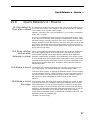
Quick Reference - How to ...
37
(R)
37
Use delays to Time align drivers
Keep relative delays while delaying a
group
37
Name a band
37
Make a band full range
37
Add EQ for Constant Directivity horns 38
Loading custom logos
38
16.1
16.2
PC Card
Card types
PC Card format
39
39
39
17.1
17.2
17.3
17.4
17.5
System Security
Program lock
Lock mode
OWNER lock
OEM lock
Safe
40
40
40
40
41
42
18.0
Troubleshooting
43
19.0
Warranty Information
44
20.0
Specifications
45
15.1
15.2
16.0
17.0
Index
User Notes
Spare Parts Information
4
Quick Reference
Quick Start - Reference
FDS-355
Omnidrive
AC Power connection
The FDS-355 has a universal voltage AC Power input. Connect the FDS-355 to
AC Power with the lead supplied. The unit will switch on automatically (there
is no separate on/off switch). The display will show the default screen, with
the current program (if selected), and overall system response curves.
Audio connections
Connect the inputs and outputs as desired. All inputs and outputs are
electronically balanced, with Pin 2 hot signal (+ve). Do not put any audio
through the unit at this time.
Program settings
If your FDS-355 has been already configured with a program, you only need to
use the RECALL mode to set the parameters to that program.
Press RECALL. Turn the parameter wheel to select the designated program
(which has a number and name) and press RECALL again. Programs marked
with diamonds are ‘OEM’ programs and have been designed to match specific
sound systems.
Some units will be locked (refer to section 17.0; System Security) to a
specific program. In this case most controls will be disabled and the unit will
be ready for use.
Recalling a program from a PC Card
To load a file from a PC card, push the card into the slot on the front panel of
the FDS-355. Press RECALL. Push the DOWN key to highlight 'Int', and turn
the encoder to select CPrg (or CAll for a full PC Card recall). Push the UP key
to return to file selection, and turn the parameter wheel to select the file. Push
RECALL again to recall the file.
Setting up a system
To configure your FDS-355, the mode of the unit should be decided upon
before setting up.
Once the Config is set (In the Utilities menu), the crossover points, individual
band delays, any EQ, and limiter thresholds can be set up.
To enter the Utilities menu, press the UP key from the default screen.
Configuring the FDS-355
The FDS-355 has 2 modes from which the unit can be configured: Stereo 2Way with sub (Stereo), or Mono 5-way (MONO). To select the mode you wish
to use, enter the Utilities menu, and press the UP key until you reach the
Config screen. Turn the parameter wheel to select the option you wish to use.
NOTE: When the configuration is changed, the unit will prompt for
confirmation of the action. If the STORE key is pressed, then the mode will
change, and DEFAULT VALUES WILL BE RESTORED. It is advisable to do a
'Store' before changing modes if you have set up a program.
5
Quick Reference
Setting the crossover points
Select the band to be edited by pushing the parameter wheel to cycle through
inputs and outputs. Note the LEDs above each channel change as the screen
changes.
Once the band has been selected, press the UP/DOWN keys until the first
crossover (Filter shape - Low slope) screen appears. Select the type of filter
shape by using the parameter wheel to cycle through the selection. Refer to
section 9.0; Outputs Menu for more info on crossover filter shapes. Pushing the
UP key from here will move to the Filter Frequency (Low slope) screen. Use
the parameter wheel to select the frequency. The high slope screen are then
access after this screen by pushing the UP key (once or twice).
Band delays
Use the UP/DOWN keys until the delay screen appears. The delay is adjusted
using the parameter wheel. Default settings for display and adjustment of
delay is in meters (m), but can be changed to milliseconds (ms), or feet/inches
(ft).
Bands can also be linked so multiple outputs can be delayed as one using the
delay link facility.
Adding EQ
Use the UP/DOWN keys to move to the EQ screen. The EQ shape can be
edited first. The shape of the EQ can be selected from one of the following by
turning the parameter wheel:
Hi-Shelf with 12dB slope (Hi12)
Hi-Shelf with 6dB slope (Hi6)
BELL
Low-Shelf with 6dB slope (Lo6)
Low-Shelf with 12dB slope (Lo12).
Pushing the UP key from the EQ shape screen will access the following
screens, in this order:
Filter Frequency screen
Cut/Boost screen
Filter Bandwidth screen
Setting the limiters
There are two screens associated with the limiters of the FDS-355, which
allow you to:
Turn the limiters on/off
Adjust the limiter threshold..
In the limiter on/off screen, turning the parameter wheel will select whether
the limiters are on or not. Pushing the UP key from this screen will access the
limiter threshold screen, and turning the parameter wheel will change the
threshold. The output meters are calibrated to this threshold, so the threshold
will show as '0' on the meter at all times, even if the limiters are off. The
thresholds are indicated in dBu, but can be changed to mV via the Limiter
Units screen in the utilities menu.
6
Automatic Phase Compensation
Automatic phase compensation is employed in the FDS-355 to maintain zero
phase difference between adjacent bands, even in 4 and 5-Way systems,
where the phase errors due to the effects of closely spaced crossover filters
can be significant. Phase compensation helps you to keep the response of the
system with the minimum of 'fiddle factor' adjustments.
Headroom Management System (H.M.S)
Headroom Management System manipulates the gain structure to make
maximum use of the dynamic range of critical components, resulting in lower
noise levels with sensitive amplifiers, where limiter thresholds are low.
7
Introduction
1.0
Introduction
1.1 OMNIDRIVE TM
Compact
Loudspeaker
Management
System
An arrangement of 3 inputs and 5 outputs, and an additional internal sum of
inputs A&B, can be matrixed in any combination to provide a complete
loudspeaker management system with integral crossovers, delays, EQ, and
protection limiters.
In stage monitor systems, the FDS-355 can function as a dual bi-amp crossover
with delay, limiters and EQ, providing a solution to on-stage hotspots caused
by monitors with identical signals, which can be eliminated by applying small
delays between wedges.
Furthermore, the FDS-355 can function as a distribution unit to multizone
systems where crossovers may be passive or local to the loudspeaker. In this
case, the provision of delays and EQ can radically enhance such a system,
while reducing both processing costs and required rack space.
The FDS-355 brings the power and usability of OMNIDRIVE into 1U of rack
space. It has new 24-bit A-D input converters giving further improvement in
dynamic range, together with the familiar OMNIDRIVE 20-bit D-A converters.
A new BSS technique has been used, which combines system software and
hardware to optimise the performance of the output converters. This ensures
that the D-A is always operating at full range, minimising converter noise
whatever the system operating level.
All the system operating software is held in flash EPROM, which means that
upgrading to new software is easy - either via PC card or from a PC via the
MIDI or RS-232 ports. 60 internal program locations are available to the user
for storing system setups, which may be generic system programs or complete
venue settings. These memories may be stored onto a PC card for backup or
archiving. The FDS-355 can also be configured as a fully secure unit, with
password protection at multiple levels to prevent unauthorised tampering.
1.2 Other features • Crossover slopes of 6,12, 18, 24 or 48dB per octave, filter types Butterworth,
Bessel or Linkwitz-Riley, as appropriate.
• Output limiters on each band (mid-filter).
• High resolution input and output delays up to 1.3 seconds in 11
microsecond steps.
• Input LED metering, showing signals from -20dB to clip level.
• Output LED metering, showing signals from -20dB to +6dB over limit
threshold.
• Front panel output level trims and Mutes
• Polarity reverse on each output.
• Phase adjustment for each output.
• PC card port for storage and recall of program settings
• Electronically balanced inputs and outputs with transformer options.
• MIDI and RS-232 ports on rear panel.
8
Voltage/Fusing
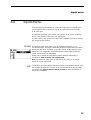
Unpacking
1.3 Voltage setting
The FDS-355 uses a switched-mode power supply which offers high efficiency
and low heat generation. This power supply accepts universal AC Power input
voltages in the range 100V AC to 240V AC (nominal), and requires no setting
adjustment for AC power voltages in this range. Minimum AC input voltage is
90 Volts, and the maximum is 264 volts.
Outside these ranges the unit will not work satisfactorily, if at all. Voltages in
excess of the maximum will probably cause damage. Voltages below the
minimum will cause complete system shutdown. The flash memory in the unit
will preserve all data in the event of a power failure.
1.4 AC Power
fusing
The Green-and-Yellow wire of the mains cord must always be connected to an
installation Safety Earth or Ground. The Earth is essential for personal safety as
well as the correct operation of the system, and is internally connected to all
exposed metal surfaces. Any rack framework into which this unit may be
mounted is assumed to be connected to the same grounding circuit.
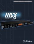
The incoming mains power is fused within the FDS-355 by the fuse holder
mounted on the rear panel. Always replace with an identical 20mm x 5mm
'T' fuse, rated at 1A for continued protection from equipment damage and fire.
Spare fuses of the correct rating are supplied with the unit.
It is most important for continued safety that this specification is strictly
adhered to.
Fig 1.1 Mains fuse on
rear panel.
2.0
Unpacking
As part of BSS' system of quality control, this product is carefully inspected
before packing to ensure flawless appearance.
After unpacking the unit, please inspect for any physical damage and retain
the shipping carton and ALL relevant packing materials for use should the unit
need returning.
In the event that damage has occurred, please notify your dealer
immediately, so that a written claim to cover the damages can be initiated.
See Section 19.0.
9
Mechanical Installation
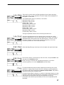
3.0
Mechanical Installation
A vertical rack space of 1U (1¾" / 44.5 mm high) is required. Ventilation gaps
are unnecessary (See Figure 3.1).
If the FDS-355 is likely to undergo extreme vibration through extensive road
trucking and touring, it is advisable to support the unit at the rear and/or sides
to lessen the stress on the front mounting flange. The necessary support can
generally be bought ready-built as a rack tray. As with any low-level signal
processing electronics, it is best to avoid mounting the unit next to a strong
source of magnetic radiation, for example, a high power amplifier, to help
keep residual noise levels in the system to a minimum.
Fig 3.1 Unit
dimensions.
Fig 3.2 Rack
dimensions.
10
Mains Power Connection
4.0
Mains Power Connection
4.1 Mains power
Refer also to sections 1.3 and 1.4; Voltage setting and AC Power Fusing.
WARNING! THIS APPLIANCE MUST BE EARTHED.
IMPORTANT: The wires in the mains lead are colour coded in accordance
with the following code.
Green and Yellow......Earth
Blue......Neutral
Brown......Live
As the colours of the wires in the mains lead may not correspond with
the markings identifying the terminals in your plug, proceed as
follows.
! The wire which is coloured Green and Yellow or Green must be connected
to the terminal which is marked with the letter ‘E’ or by the Earth signal
or which is coloured Green and Yellow or Green.
" The wire which is coloured Blue must be connected to the terminal
labelled ‘N’ or coloured Black or Blue.
# The wire which is coloured Brown must be connected to the terminal
labelled ‘L’ or coloured Red or Brown.
Those units supplied to the North American market will have an integral
moulded 3 pin connector which is provided to satisfy required local standards.
11
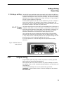
Front Panel Controls
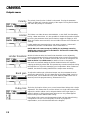
5.0
Controls
5.1 Input section
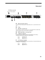
Fig 5.1 Front panel
A
Store key
Program data can be stored to either internal memory, or a PC card, and is
done by using the store facility. The STORE key also doubles as an ENTER key
for confirmation of some actions.
Refer to section 11.1; Storing
B
Recall key
Program data is recalled to the unit from either internal memory or a PC card
using the recall facility.
Refer to section 11.2; Recalling
C
UP/DOWN Keys
Controller keys for editing parameters displayed by the LCD screen.
D
Mode LEDs
Displays whether the FDS-355 is currently in Utils, Store or Recall mode.
E
Main Display
The main LCD screen displays current parameters being edited with numerical
and graphical representations. When the user is not editing, the screen can
display the overall system response, or a custom logo.
F
Encoder (Parameter wheel)
The encoder/parameter wheel is used in conjunction with the UP/DOWN keys
to input or select information, and also to move between screens. Pushing and
holding the wheel in will return you to the default screen after a few seconds.
Pushing and holding the encoder, then pressing a mute button, will take the
display to the corresponding output channel.
G
Input meter
Input signal level referenced to the clip level. Actual signal clipping will
occur slightly above the 'clip' indicator.
12
H
PC card slot
The card slot is used for storing/recalling program data via a PC card.
Refer to section 16.0; PC Card for more information.
J
Input LEDs
These indicate which (combination of) input channels are being edited. The
Card LED underneath illuminates when a PC Card is inserted into the front
panel slot.
Note: If all three input LEDs illuminate at once (which is highly unlikely), the
unit is clipping internally due to large amounts of EQ or gain being added.
K
Output controls
Refer to section 5.2; Output section for more detail.
13
Output section
5.2 Output section
Fig 5.2 Output section
A
Edit LED
Lights up when the output is being edited.
B
C
Output meter
Mute LED
Shows the mute status of the output band.
D
Mute key
Pressing a mute key will toggle the associated band output on and off. The
mute LED is illuminated when the output is MUTED. Mute status is saved
when a program is stored.
E
Gain trim
Each output band can be trimmed for output level across a range of -6dB to
+6dB.
14
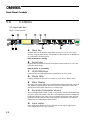
Rear panel
5.3 Rear panel
Fig 5.3 Rear panel
A
Mains power input
The Power inlet for the FDS-355. Note that there is no On/Off switch for the
unit.
B
C
Fuse
RS-232 connector
For connection to a PC for access to one or more FDS-355s on a MIDI loop,
which provides an easy way to upload new software.
D
E
MIDI interface connectors
5 Band outputs
The FDS-355 audio outputs are electronically balanced and floating.
Transformer balancing is available as a retrofit option.
Pin 1
Pin 2
Pin 3
F
Shield/Ground
Signal Hot (+)
Signal Cold (-)
3 Channel inputs
The FDS-355 audio inputs are electronically balanced. Transformer balancing
is available as a retrofit option.
Pin 1
Pin 2
Pin 3
Open circuit
Signal Hot (+)
Signal Cold (-)
15
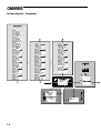
Screen layout - Overview
16
Moving about the screens
Use the parameter wheel to move between Default, Utility, Input and Output menus (Vertical
columns). Pushing the wheel in, or pushing and holding the wheel in while turning clockwise, will
move to the next screen on the right. Pushing and holding the wheel while turning anti-clockwise
will move you a screen to the left. Each menu is shaded with a different colour to identify each
seperate menu structure. Pushing and holding the wheel in will return you to the default screen after
a few seconds. Pushing and holding the encoder, then pressing a mute button, will take the display
to the corresponding output channel.
Use the UP and DOWN keys to move up and down within each menu. The Utility and Output
menus are displayed here in multiple columns since they have too many screens to display in one
long column.
Moving to a new menu may not bring up the first (bottom) screen shown in each column, as the
FDS-355 remembers, and moves you to, the last screen accessed in each menu.
Store and Recall are accessed by pressing their respective keys. Refer to section 11.0 for more
information.
17
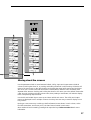
Key screens
After powering up, the FDS-355 performs internal checks and sets up the audio
path before releasing the output mute relays. This takes a few seconds.
Refer to section 6.0; Default screen.
Utilities
Pushing the UP key will enter the Utilities Mode. Many of the utility screens
are self explanatory (see Screen layout on the previous two pages), but the
more important ones are shown below.
The display shows the currently selected utility at the top of the screen, and
the previous 3 available utilities underneath.
The stereo link screen shows whether the unit is operating in a linked mode or
not.
Refer to section 7.0; Utilities menu.
The configuration screen changes the output mode of the unit.
Refer to section 7.0; Utilities menu.
The MIDI details screens allows the user to select the MIDI channel and the
MIDI mode of the unit.
Refer to section 7.0; Utilities menu.
Input settings
Pushing the parameter wheel again (at any time in the Default or Utilities
menu) will enter Inputs Mode. Here the parameters of each input can be
adjusted.
The delay screen shows the delay value set for each input.
Refer to section 8.0; Inputs menu.
The next screen allows the user to edit the filter parameters in the following
order: EQ shape, Frequency, Cut/Boost, and Width. Each filter is dealt with on
a seperate screen. Therefore, all of the first filter parameters will be accessed
before moving on to the parameters of the second filter, and so on...
Refer to section 10.0; EQ screens.
18
Output settings
The name screen. Allows each output to be given a descriptive name from a
preset list.
Refer to section 9.0; Outputs menu.
The source screen allows the user to configure the routing of the inputs to the
outputs.
Refer to section 9.0; Outputs menu.
The Xover screens allow each edge of the crossover point to be adjusted,
using the following parameters: Polarity, Phase, Low and Hi Filter shape, and
Low and Hi crossover frequency.
Refer to section 9.0; Outputs menu.
The Limiter and Gain screens allow output gain and limiter settings to be
changed.
Refer to section 9.0; Outputs menu.
The Delay and Delay Link allow delay to be applied to the each output, and
also allow linking for changing delay on multiple outputs simultaneously.
Refer to section 9.0; Outputs menu.
The next screen allows the user to edit the filter parameters in the following
order: EQ shape, Frequency, Cut/Boost, and Width. Each filter is dealt with on
a seperate screen. Therefore, all of the first filter parameters will be accessed
before moving on to the parameters of the second filter, and so on...
Refer to section 10.0; EQ screens.
Pushing the parameter wheel again (at any time in the Outputs menu) will
return to the Default/Utilities screen.
19
Default screen
6.0
Default Screen
Program
number
Program
name
Output band
curves
Unsaved
changes flag
When the FDS-355 is powered up the Default Screen is shown. This gives a
representation of the current state of the unit. If the unit has Lock Out mode
ON, the Default screen will be replaced by the current start up logo, along
with the current program name and number.
The main area of the screen contains the three output band curves. Each band
curve represents the frequency response of the high and pass crossover rolloffs,
in addition to any equalisation filters that have been used (and are not
hidden).
The XOver frequencies are adjusted in the Outputs menus, refer to section
8.0; Outputs menu.
Equalisation can be adjusted in the EQ screen of the Inputs and Outputs
menus, refer to sections 10.0; EQ screens.
20
Utilities menu
7.0
Utilities Menu
Selected
utility
Previous 3
utilities
Selected utility
parameter
Pushing the UP key while viewing the default screen will move you into the
Utilities menu. The UP and DOWN keys are used to move along the
'Utilities' path, and the parameter wheel is used to change the selected
parameter. If confirmation of an action is required, the STORE key should be
pressed. Screens are shown here with only the described utility for clarity.
Stereo link
This mode selects whether parameters will be adjusted together, or
independently on each channel.
Turning the parameter wheel clockwise selects Stereo Link: ON, and
anticlockwise selects OFF.
Configuration
The Configuration facility defines the general operating mode for the FDS355; either Mono or Dual/Stereo 2-Way ("Stereo"). The parameter wheel is
used to select the desired configuration.
The Mono mode (by default) assigns all outputs to input A, but it is possible to
re-route any inputs and outputs after selecting a configuration.
By default, the stereo 2-Way mode will set up the unit as follows:
Input A (Left) to Outputs 2 & 4.
Input B (Right) to Outputs 3 & 5
Input C (Sub) to Output 1.
NOTE: When the configuration is changed, the unit will prompt for
confirmation of the action. If the STORE key is pressed, then the mode will
change, and DEFAULT VALUES WILL BE RESTORED. It is advisable to do a
'Store' before changing modes if you have set up a program.
21
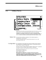
Utilities menu
Delay correction
Temperature
Delay units
Limit units
Lock out
Allows a delay correction to be entered, to compensate for ambient
temperature. With Delay Corrn set to 'Off', the default temperature is set to
20°C. Setting Delay Corrn to 'Manual' allows a user defined value to be
entered, from -20°C to 50°C, in 1°C increments. If Delay Corrn is set to 'Midi',
then the temperature value can be taken from a temperature probe connected
to a 388. If the 355 is used with a single 388, then the 355 MIDI input should
be attached to the MIDI output of the 388. The 388 should be set to
MIDI:XMIT MET.
Sets the ambient temperature manually, if Delay Corrn is set to 'Manual'.
This selects the units used for displaying and adjusting delays. 'ms' represents
milliseconds, 'ft' represents feet (and feet and inches for short delays), and 'm'
represents metres. 24, 25 and 30fps represent delays using 24, 25 and 30
frames per second respectively. Note that for longer delays, the resolution of
the parameter wheel is reduced to match the number of decimal places
displayed,. Short delays will adjust in approximately 11us increments, whilst
longer delays will adjust in 100us increments.
The limit units screen allows the units of limiter threshold to be changed
between dBu and mV, depending on your amplifier specification.
The Lock Out mode prevents access to editing functions on the input and
output channels. Since this utility is not password-protected, Lock Out can
still be accessed and turned off. This mode is intended only as a precaution
against accidental adjustments, and not as a tamper-proof security lock
For other security details, refer to section 17.0; System Security.
MIDI channel
MIDI mode
Here, you can select the MIDI channel that the unit is assigned to (Channels 1
through 16 are available).
The selection of this mode sets what the FDS-355 may transmit on it's MIDI
OUT socket, and depends on the use of the FDS-355 in the system. The
possible selections are:
OFF
The OFF mode prevents MIDI messages being transmitted.
PROGRAM
The PROG mode enables the unit to transmit only MIDI program changes.
MASTER
The MASTER mode transmits all control changes to other devices on the same
MID channel. (For paralleling two FDS-355s, for example).
THRU
The THRU mode allows the FDS-355 to pass incoming data on to it's MIDI
OUT socket. (As required by the BSS MIDI network used in the FPC-900r and
Soundbench systems).
PC PORT
The PC PORT mode allows the unit to be connected directly to a PC via the
RS-232 port.
22
Contrast
Brightness
Owner lock
This allows you to change the contrast of the LCD display.
This allows you to change the brightness of the LCD display.
The Owner Lock screen allows the owner of the unit to program a system and
then lock the unit against being reset. Individual OEM locked parameters
cannot be unlocked with the Owner Lock, and the owner cannot view OEM
locked parameters.
To enter Owner lock, change the lock status from OFF to ACTIVE. The unit
will always prompt for the default password, which is 'OMNI' for Owner lock.
Use the parameter wheel to cycle through characters, and the UP and DOWN
keys (or push the parameter wheel) to change position in the password. Once
the default password has been entered, press the STORE key to enter Owner
lock setup mode. The screens for any parameter can then be accessed in the
usual manner, turning the parameter wheel clockwise to lock the parameter.
Once the setup is complete, press the STORE key again to save the owner
lock setup. The unit will then prompt the user to enter a user password, and
then press STORE again to confirm and exit Owner lock setup.
To change Owner lock mode (from ACTIVE to OFF), the user Owner password
must be entered.
NOTE: There is no way to turn Owner lock off if the password has been
forgotten! Refer to section 17.0; System Security for more information.
OEM lock
OEM Lock screen allows P.A. system manufacturers to lock the unit, so that
certain parameters cannot be viewed and edited. OEM lock is the highest
level of security of the unit, and can lock out any parameter of the unit.
To enter OEM lock, change the lock status from OFF to ACTIVE. The unit will
always prompt for the default password, which is 'BSS' for OEM lock. Use the
parameter wheel to cycle through characters, and the UP and DOWN keys (or
push the parameter wheel) to change position in the password. Once the
password has been entered, press the STORE key to enter OEM lock setup
mode. The screens for any parameter can then be accessed in the usual
manner, turning the parameter wheel clockwise to lock the parameter. Once
the setup is complete, press the STORE key again to save the OEM lock
setup. The unit will then prompt the user to enter a user password, and then
press STORE again to confirm and exit Owner lock setup.
To change OEM lock mode (from ACTIVE to OFF), the User OEM password
must be entered.
NOTE: There is no way to turn OEM lock off if the password has been
forgotten! Refer to section 17.0; System Security for more information.
Xover adjust
The Xover Adjust determines how crossover points are adjusted relative to the
corresponding edge of the adjacent band. The following options may be
selected:
BOTH
When set to BOTH, both the upper band edge of the lower band and the lower
band edge of the upper band are adjusted as a pair. This means that only one
filter adjustment is required to set a crossover point, and the graphic display
shows both edges moving together.
23
Utilities menu
NOTE: You can select either band in order to adjust the crossover - the lower
band or upper band - and either adjustment will move both band edges
together, updating the data for the other band.
EDGE
When set to Edge mode, each band edge is adjustable independently. This
allows the possibility to create band overlaps at the crossover point.
Backup and Swap
Defaults to 'Off'. This function allows the user to make subtle adjustments to a
setup, and then compare the changes to the original setup.
With this facility turned on, the store and recall buttons are reprogrammed to
perform backup and recall respectively. Pressing the Store (Backup) button
will copy the current setup to the internal clipboard. Changes can then be
made to the setup, and then the Recall (Swap) button can be pressed to toggle
between the two setups to compare them audibly. This function has no effect
in the following circumstances:
•
Immediately after boot-up, as the backup is empty.
•
Immediately after the setup has been backed-up; since pressing the
Recall (Swap) button toggles between two identical setups.
Note: Backup & Swap works only when a parameter of the program is being
edited. I.e: When the unit is in an input or output mode.
With this option turned on, a Store or Recall can ONLY be performed from
the default screen, or utilities menu.
Store gain trims
(Turn to) MIDI
dump
This feature allows the front panel gain trims values to be stored with the
program. The 355 adds the front panel value to the band gain value for each
output. Therefore, when recalling a program, the unit will warn to set ALL
front panel trim values to zero.
This mode allows you to dump the current program settings to another FDS355, or a MIDI storage device for backup.
The default position for this screen is MIDI DUMP: NO. Turning the parameter
wheel to YES will ask you to press STORE to confirm the dump. A percentage
complete figure will show how much data has been transferred. When the
dump is complete, the screen defaults to NO.
If you are using the MIDI Dump to transfer data to another FDS-355, ensure
that both devices are set to the same MIDI channel, and connect the MIDI
OUT of the sending device to the MIDI IN of the receiving device. The MIDI
Dump mode is totally independent of the MIDI MODE.
NOTE: All parameter edits in all stored programs will be overwritten in any
FDS-355 set to the same MIDI channel. Use MIDI Dump with care!
24
(Turn to) Delete
program
This facility allow any stored program to be removed from the unit. Use the
parameter wheel to select the desired program, and press STORE to confirm
deletion.
(Turn to) Format
card
For this mode to be enabled, a PC card must be present in the slot at the front
of the unit. To begin the format, turn the parameter wheel clockwise, and the
unit will prompt for STORE to be pressed to confirm the action. When the card
is formatted, the screen will default to NO.
NOTE: ANY DATA ON THE CARD WILL BE LOST DURING A FORMAT.
Inputs menu
8.0
Inputs Menu
There are three inputs available for routing to outputs plus an internal mono
sum of inputs A and B, referred to as A+B. This gives the Input Channels:
A, B, A+B, and C.
The facilities described in this section are common to all inputs, except EQ,
which is not possible on the mono sum A+B signal.
The first screen in the input menu is the DELAY SCREEN. Pressing the UP key
will access the EQ screens.
Delay
The delay on each input channel can be adjusted individually, in 11
microsecond steps. Turning the parameter wheel will set the amount of delay
required on the input. This delay is typically used to set the delay for delay
towers etc, or to stagger the delays between the left and right channels to
‘move’ sound lobes in an installation.
Delays can be viewed and adjusted in metres (default), feet/inches, or
milliseconds. Refer to section 7.0; Utilities menu.
Note: The maximum delay value is restricted by any delay on an output
which the current input feeds.
EQ
To add EQ to an input, step through the functions on the desired channel using
the UP/DOWN keys until you reach the screen that shows the EQ parameter
you wish to edit. Refer to section 10.0; EQ screens for more information on
editing EQ parameters.
25
Outputs menu
9.0
Outputs Menu
To select any one of the 5 output bands, press the parameter wheel until the
output is shown on the screen, and the EDIT led above the desired channel
illuminates. Pushing and holding the encoder, then pressing a mute button,
will take the display to the corresponding output channel.
Name
The first screen in the Output menu is the Name function. Here you can
identify each output with a name suitable to its function, selecting from a list
of names in the FDS-355, such as SUB, or 2” HORN.
Turn the parameter wheel to select the desired name. If the name selected
while stereo is NOT linked begins with L<space> or R<space>, then the L or
R will not be displayed when stereo linking is on.
Source
This screen gives a graphical representation of the input to output assignment
matrix. The channel selected has its speaker icon highlighted, and a
connecting line shows to which input it is currently assigned. The input source
name is also shown above the diagram.
Note that the diagram shows straight through connections from inputs to
outputs, omitting any internal processing (EQ, Xover etc) for clarity.
To change the source input, turn the parameter wheel until the speaker icon is
connected to the desired source.
Note: The speaker icons are not drawn in a fixed order. The diagram will be
drawn in the clearest way, to avoid lines crossing on the screen. Therefore
care must be taken when changing input to output assignments, as the
numbers next to the speaker icons (representing the outputs) will change
positions.
26
Low shape
This screen is used to select the filter type/shape for the lower band edge
(high-pass) of the current output band. The band edge will be highlighted on
the graphic on the screen.
The available filter types are as follows, in this order:
Butterworth 6dB / Octave
Butterworth 12dB /Octave
Bessel 12dB / Octave
Linkwitz-Riley 12dB Octave
Butterworth 18dB / Octave
Butterworth 24dB / Octave
Bessel 24dB / Octave
Linkwitz-Riley 24dB / Octave
Butterworth 48dB / Octave
Linkwitz-Riley 48dB / Octave
Turning the parameter wheel will scroll through the above list.
Low Xover
The lower edge (high-pass) of the crossover band can be set over a wide
frequency range from OUT (no roll off) through 15Hz to 16kHz. Turning the
parameter wheel anticlockwise will lower the frequency, with OUT as the
final step. Turning it clockwise will increase the frequency, to the final
clockwise position OFF, which mutes the output.
High shape
Selects the Edge filter type and slope as for the higher (low-pass) band edge.
High Xover
This function works in a similar way to the Low Xover, except that OUT is the
last step at the clockwise position.
NOTE: Turning it clockwise will decrease the frequency, to the final
clockwise position OUT, which DOES NOT mute the output.
Phase
The phase relationship of the two band edges at the crossover point can be
adjusted in 5 degree steps using this function. Adding any phase adjustment
will utilise an EQ filter as described in section 10.0; EQ screens. The phase is
adjusted by turning the parameter wheel.
The phase angle reference frequency is set by the high edge frequency so that
this band controls the phase between the current band, and the band above it.
Adjustments should therefore start with the highest band, and work
downwards. Note that the topmost band(s) do not have an adjustable phase
parameter.
27
Outputs menu
Polarity
Limiter
The polarity invert function. Default is uninverted. Turning the parameter
wheel clockwise will invert the polarity of the output. Turning anticlockwise
will return the polarity to uninverted.
The limiters can either be set to ON NORMAL, or ON FAST; the fast setting
having a faster attack time. It is also possible to disable the protective limiters
by turning the parameter wheel anticlockwise to toggle the display to OFF.
When the limiters are turned OFF, the red OVER indicator will illuminate as a
warning.
Limiter settings are preserved when a user saves a program - limiters will
automatically be set to ON NORMAL if the limiters were on.
NOTE: BSS Audio cannot accept any liability for any damage caused by
disabling the protective limiters in the FDS-355. This function is used totally
at the discretion of the user.
Limiter threshold
With the limiters enabled, the band limiter threshold can be adjusted by
turning the parameter wheel to set the desired value to match the sensitivity
of the amplifier in use. The default units are dBu, but can be changed to mV.
Refer to section 7.0; Utilities menu for details on how to change this.
BSS Audio recommends setting the limiter thresholds below the amplifier
clipping sensitivity by about 2dB. This prevents any transient overshoot driving
the amplifier into clip and so damaging your loudspeakers. When limiters are
disabled, the threshold setting determines the output meter sensitivity.
Band gain
To adjust the relative gain of the band output, turn the parameter wheel to
achieve the desired level. This is independent of the output TRIM control on
the front panel, and is additional to any level added by TRIM. Band Gain is
stored as part of the program memory, whereas trim is not.
Delay link
The Delay Link option allows you to control several band delays with a single
adjustment. This means that once all the drivers in a single cabinet have been
aligned, the whole cabinet can be delayed relative to the input signal, or
another cabinet, by linking these band delays as one. Any offsets applied
before linking will be retained after linking.
In the Delay Link screen, turn the parameter wheel until the desired linking
configuration is shown. The linking setup is shown by a graphical
representation, and is also described above the diagram.
28
Delay
The band delays are most often used to electronically align the driver voice
coils with the other drivers in the system, so the sound sources are coherent in
the physical plane.
Each increment is only 11 microseconds, which translates in physical terms to
a distance of 3.4mm, giving high accuracy in terms of alignment.
If delay units are set to f.p.s., then the value can be adjusted in half frame
increments. The 355 will automatically convert the value of the delay, if
delay units is changed from distance to f.p.s. in the utility menu, and vice
versa. This also allows fine tuning once a value has been set in frames.
Turn the parameter wheel to move the icons left and right. The actual delay
value is shown above the diagram, and the icons in the display represent the
offsets between each output.
EQ
To add EQ to an input, step through the functions on the desired channel using
the UP/DOWN keys until you reach the screen that shows the EQ parameter
you wish to edit. Refer to section 10.0; EQ screens for more information on
editing EQ parameters.
29
EQ menu
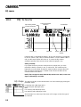
10.0
EQ Screens
Input being edited
Current Parameter
Frequency
Current Parameter
selection
Cut/boost
Unused EQs
Cursor Stereo Width
marker
If the FDS-355 is configured for MONO, all EQ’s will be mono. If configured
for 2x2+1 ("stereo"), EQ’s will be marked as Stereo 'S' when STEREO LINK is
ON, and the stereo marker will show an 'S' next to the EQ number.
Available spare EQ filters are also shown above the graphic area.
Adding a new EQ:
If you press the UP key and the screen does not change, then you have
reached the last EQ currently in use. To add an EQ, the cut/boost of the
highest EQ must be edited. Another EQ (assuming there are spare EQs) will
then be inserted automatically. A dotted contour shows the effect of the
crossover filters on this band.
NOTE: The A+B signal is mixed after the EQ sections on A and B, so the A+B
signal is affected by A and B EQ.
EQ shape
The shape of the EQ can be selected from one of the following by turning the
parameter wheel:
Hi shelving with 12dB slope (Hi12)
Hi shelving with 6dB slope (Hi6)
BELL
Low shelving with 6dB slope (Lo6)
Low shelving with 12dB slope (Lo12).
The EQ shape icon at the top of the screen will change, to show the type of
EQ selected.
30
Frequency
Turning the parameter wheel adjusts the EQ frequency. The filter position is
shown graphically by the cursor, and the Frequency of EQs can range
between 15Hz and 16kHz.
Cut/Boost
Turn the parameter wheel clockwise to add boost (+ gain) or anti-clockwise
for cut (- gain). Cut/boost is available between +15dB and -15dB, in 0.2dB
increments.
Width
Turning the parameter wheel clockwise widens the EQ (lower Q),
anticlockwise makes the EQ narrower (higher Q). EQ Width is available
between 0.05 and 3 Octaves, in 0.05 increments.
31
Store and Recall
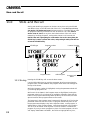
11.0
Store and Recall
Storing and Recalling a program can be done at any time using the STORE
and RECALL keys on the left hand side of the LCD, unless Backup and Swap
(see section 7.0; Backup and swap) has been turned on. The FDS-355 can hold
60 programs internally, and these can also be saved to a PC card (refer to
section 16.0; PC Card). At any time, the Default values of the unit can be
restored by recalling program 0, except when Owner Lock is turned ON.
NOTE: If the unit is prompting for confirmation of an action at any time, the
STORE key is used to conform the action, and pressing it at this point will not
access the STORE facility.
STORE type
Program number
Program Name
11.1 Storing
OEM Program
Unsaved changes
flag
Program Lock
status
Pressing the STORE key will access the Store screen.
Use the UP/DOWN keys (or push the parameter wheel) to move along the
program name, and also between the program name and the STORE type at
the top of the screen.
While the Program number is highlighted, turning the parameter wheel will
cycle through programs 1-60.
While each of the letters in the Program name are highlighted, turning the
parameter wheel will cycle through all available characters. Note that the
letters in the program name being edited (at the top of the screen) are more
spaced out than other program names on the screen.
The last space in the program name is reserved for Program lock. Turning the
parameter wheel will turn this on/off. If a program has this flag set to on (so
the program name displays a key at the right hand side), a new program, or
edited version of the current program, cannot later be stored in this location.
This lock can be turned off at any time in order to delete or overwrite the
program. If you try to store a program in place of a locked program, the unit
will display "PROGRAM LOCKED!", but will then highlight the key icon,
32
giving you the option to turn off the lock if you wish to overwrite the existing
program.
STORE TYPE There are 3 ways in which data can be stored, and these are indicated by the
STORE TYPE message at the top of the display. To highlight the Store type
message, use the DOWN key while a program number is highlighted. Once
highlighted, turn the parameter wheel to select the type of store you wish to
use.
INT
This stores the program in the internal memory of the unit.
CPrg
This stores the currently selected program to a PC card (if inserted) in the slot
at the front of the unit.
CAll
This stores all program data to a PC card (if inserted) in the slot at the front of
the unit.
The Program Lock can be applied to a program stored using any of these 3
methods.
NOTE: The edit flag appears when there are unsaved changes to a program,
compared to the initial status of the last recalled/stored program (Internal
memory only). When a program is stored to internal memory, the edit flag will
disappear. If a program is stored to a PC card, then the flag will NOT
disappear, since there are differences between the last recalled/stored
program (Internal), and the current program.
Once the program name has been entered, the store type selected, and the
Program lock status cleared, pressing the STORE key again will prompt the
message "STORE UNLOCKED?", asking whether the program should be stored
with a Program lock on/off. Use the parameter wheel to turn the Lock on/off,
the default setting being ON. Once the Lock status is set, push the STORE key
a final time to commit the program to memory (or PC storage). The display
will now default back to the screen displayed before the STORE facility was
accessed.
To exit from the store screen without storing a program, press the recall
button.
11.2 Recalling
Pressing the RECALL key will access the recall screen. This facility is
displayed in the same way as the store facility.
The parameter wheel is used to select the program number to recall (when
highlighted), or to select internal memory or PC card recall (when
highlighted). The UP/DOWN keys are used to toggle between Program
number and Recall type.
When the program you wish to recall has been selected, push the RECALL key
again to recall the program. The unit will display a message showing that data
is being recalled, and will then display the default screen once the recall is
complete.
To exit from the recall screen without recalling a program, press the store
button.
33
Headroom Management System (HMS)
Phase Compensation
12.0
Headroom Management System
Headroom Management System (H.M.S) is employed in the FDS-355 to make
maximum use of the dynamic range of the devices inside the unit. In systems
where limiter threshold levels are low, the output signal excursions are
restricted, and thus make poor use of the available dynamic range.
HMS makes use of a variable gain stage in the digital domain, and a variable
attenuation stage in the analogue signal path to change the gain structure.
Whenever the limiter threshold or output gain is adjusted, HMS calculates the
excess headroom and simultaneously increases both the digital gain, and the
analogue attenuation to match. Since the Digital to Analogue Converter
(DAC) and various other noise contributing components lay between these two
adjustment points, the noise appearing at the output will be reduced.
Note that HMS is not a dynamic process; it only makes adjustments to the
gain structure when the user makes adjustments. It is therefore free of side
effects.
13.0
Phase Compensation
A classic 2-Way crossover using just a high-pass and a low-pass filter will
always meet the criteria predicted for a given alignment. A 2-Way LinkwitzRiley crossover ,for example, will produce its two outputs 'everywhere in
phase', and they will acoustically combine to a flat amplitude response. The
main lobe of the polar response will also be on-axis.
When more filters are added to the crossover for more than two drivers,
however, the crossover begins to depart from the mathematical perfection of
the 2-Way case. In a 3-Way crossover, the high-pass characteristics of the mid
band will be disturbed by the phase response of the low-pass in the mid band,
and vice-versa. This results in drivers of adjacent bands being driven out of
phase, producing irregularities in the amplitude response, and pushing the
main lobe of the polar response off-axis, further aggravating amplitude
response problems in some listening positions. Although these effects may be
subtle when the crossover frequencies are well separated, 4 and 5-Way
systems can produce significant errors.
The phase compensation scheme employed in the FDS-355 analyses these
phase anomalies whenever adjustments are made, and introduces phase
adjustment into certain bands such that the phase difference between all
adjacent bands is always close to zero degrees. It will of course allow the user
to introduce intentional phase differences, using the phase and delay
parameters. The FDS-355 will not attempt to apply phase compensation if the
high and low frequencies or shapes of the adjacent bands do not match, on
the assumption that the user does not expect to produce a standard alignment.
34
Typical Applications
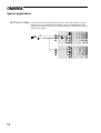
14.0
Typical Applications
The FDS-355 has three inputs: A, B, C. An internal mono sum of inputs A & B
is also available for routing to any of the outputs. Any combination of routing
inputs to outputs is available, and the FDS-355 can be configured as a stereo
or mono device.
14.1 Stereo 2-Way
with a mono subbass.
Systems can be run as simple stereo 2-Way, or with an additional sub-bass
output (Mono). This sub-bass can be derived from either a mono sum of the
stereo inputs, or from a separate input using an aux send from the console.
To use the FDS-355 in this mode, configure the unit as 2 X 2+1 (stereo) in the
Configuration screen of the Utilities menu.
Use inputs A and B for the stereo inputs, and Outputs 2-5 for the Output bands
(Bands 2 and 3 are Lo left and right, and bands 4 and 5 are Hi left and right
respectively). The sub output 1 should be sourced from the mono sum A+B, or
input C for an independent sub-bass feed.
The Stereo Link ON mode allows the same parameters on the left and right
channels to be adjusted simultaneously and any edits made Unlinked are
preserve the left/right difference as an offset.
14.2 Dual Bi-amp
(Stage monitors)
The FDS-355 can provide 2 channels of bi-amp crossover for monitor racks
with EQ, delays, and limiters. With so much EQ available in the FDS-355, it
is easy to assign 12 bands of EQ to the input, as well as EQ to the output
bands, saving the need for external EQ.
For example: Input A would feed Outputs 1 and 2, with Input B feeding
outputs 3 and 4. Set the configuration to Mono in the Utilities menu, and
adjust the SOURCE mode accordingly.
In this mode, it is possible to remove ‘hot spots’ on stage. Where the same
mix is sent to a number of performers, interaction between wedges can create
lobes of high intensity which creates confusion. Using a fine delay to shift
wedge feeds can move these hot-spots to less sensitive areas on stage.
14.3 5-Way zoning
distribution
The FDS-355 can be also be used as a zone distribution system, without using
any of its crossover facilities. Using this mode, a common input signal can be
routed to up to 5 separate outputs, each with delays, EQ and limiters.
Typical uses for this mode would include feeding a number of under-balcony
loudspeakers with integral passive crossovers, using the delays of the FDS-355
for time correction, and EQ for tuning response. For this application, each
output should be full range, unless you particularly want to band restrict the
outputs.
Use the Xover Freq screens in the Outputs Menu to set each band edge to be
OUT.
35
Typical Applications
14.4 Mono 5-Way
36
In the mono mode, the FDS-355 can provide a full 5-way system. It can also
function as a 4-way system fed from input A, with an independent sub-bass
output fed from input C (or B). Two FDS-355s working in this mode can form a
stereo 5-way system.
Quick Reference - How to ...
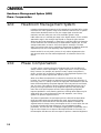
15.0
Quick Reference - How to ...
15.1 Use delays to
Time align® drivers
The best way to do this is to have a good idea of the physical positions of the
voice coils of the drivers in the cabinet. If you do not know this, an estimate
can be made, but it may take a while longer.
Assume a 3-way box; with a 12” direct radiator, a 2” horn with a compression
driver, and a 1” bullet.
The voice-coil furthest away from the front of the cabinet will be the 2” horn,
so the other two drivers will need delaying to compensate for the time it takes
the audio energy to reach the outer flare of the horn. This distance could be
300mm. Subtract from this the distance of the voice coil of the low driver (lets
say 120mm) and set that delay to the result (180mm). Do the same for the 1”
bullet, which will usually have a shorter distance from voice coil to front, and
hence need a longer delay.
15.2 Keep relative
delays while
delaying a group
15.3 Name a band
This is achieved by using the DELAY LINK mode. Any bands can be linked so
that a delay applied acts to all the linked bands. This means that relative
shifts between cabinets can be made without upsetting driver alignments.
Select the output band to be linked in the outputs menu, then use the UP key
to cycle through the screens until the Delay Link screen is shown. Turning the
parameter wheel will show all possible choices, which are determined by the
bands sourced from the same input. The graphic display will also show the
bands being linked.
The FDS-355 has a preset list of names you can select from which may suit
your system layout. For example, Output 1 can be renamed to Subs.
To do this, select Output 1 by pushing the parameter wheel. Once the Output
1 screen has been selected, use the DOWN key to select the Name screen (if
not already shown). Turn the parameter wheel to select a relevant name for
the output. The name is automatically retained when a new screen is
selected.
15.4 Make a band
full range
In the utilities menu, the Xover mode must be changed from 'Xover' to 'Edge'.
Then select the band to be edited by pushing the parameter wheel. Use the
UP/DOWN keys to cycle to the Xover Frequency screen for the lower band
edge (Low Xover). Turn the parameter wheel anti-clockwise until the display
reads OUT, and the graphic shows the lower edge horizontal, with no roll-off.
Pressing the UP key twice will access the upper edge Xover Frequency
screen. Turn the parameter wheel clockwise until the display reads OUT, and
the band is shown as completely flat.
The band is now full range.
37
Quick Reference - How to ...
15.5 Add EQ for
Constant Directivity
horns
Constant Directivity horns often require additional equalisation in order to
extend their frequency response. In most cases, this is a fairly simple EQ,
requiring only a gentle slope (6dB per octave) high-pass shelving filter.
To add CD EQ, select the band to be equalised by pushing the parameter
wheel, and push the UP/DOWN keys until you reach a free EQ band refer to
section 10.0; EQ screens.
Select a 6dB, Hi Pass filter by turning the parameter wheel until the shape
icon at the top of the screen shows the graphic shown left.
Push the UP key to access the EQ Frequency, and adjust the freq by turning
the parameter wheel to show a frequency of about 2kHz (check with your
manufacturer for detailed information about Frequency and Boost
requirements for a system).
Push the UP key to access the EQ Cut/Boost, and turn the parameter wheel to
give a boost of about 6dB.
The frequency and boost values may need trimming to give the best results.
15.6 Loading
custom logos
38
Custom logos can also be loaded into the 355 using the latest BSS loader
(available from the web site). These logos must be in .GIF (87a noninterlaced) format. The resolution of the 355 screen is 128x56 pixels, and 2
colours. Logos should be drawn with a white tool on a black background.
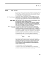
PC Card
16.0
PC Card
The PC Card socket on the front of the unit is designed to use memory cards of
between 128kbyte and 2Mbyte storage capacity. Files are stored on the card
in a ‘Pseudo-floppy’ format using standard DOS structures. See the box at the
end of this section for compatibility information.
16.1 Card types
The Smart Card interface requires 68pin compatible SRAM memory cards.
Attribute memory is not required and is not used. The most appropriate card
size for the FDS-355 is the 256k byte card which can hold approximately 14
complete setup (CAL) files.
SRAM CARDS 128k, 256k, 512k, 1M, 2M. Battery life varies with manufacturer and memory
size and should be checked with the card supplier.
Rechargeable cards are also now available. These cards should periodically
be left in the card slot of an FDS-355 for a few hours to recharge. Expected
battery life for rechargeable cards when not plugged into a unit is about one
year, but should always be checked with the card supplier.
16.2 PC Card
format
The PC Card filing system on the FDS-355 uses a ‘pseudo-floppy’ format.
Formatting a Card on the FDS-355 writes a standard PC DOS format to the
card beginning at byte 0 as if it were the first byte on a disc. The format writes
a DOS boot sector with basic format data but does not write boot software.
This is followed by a single File Allocation Table (FAT) starting at byte 200H.
The root directory is written with one entry, a sub-directory called BSSDATA.
All data files used by the unit are stored in the BSSDATA sub-directory as
there are limits to the number of files that can be stored in the root directory.
The different file types used by the unit have different file extensions as
follows. The file sizes are variable, and change with the number of EQs used,
and number of programs.
Program
All data
*.CPG
*.CAL
The ‘pseudo-floppy’ filing system as used on the unit conforms to the PC
CARD standard although it does not format Card Information Structure (CIS)
information. BSS has tested and developed the Card filing system using an
IBM compatible PC card reader and a range of palm-top computers, but
cannot guarantee that the cards can be read by any particular piece of
computer equipment. To be able to transfer files to and from an external
computer note the following:
• Always format the card on the external computer.
• Always write a sub-directory called BSSDATA into the root directory
immediately after formatting the card. All files used by the FDS-355, FDS-388
and FPC-900 remote are stored in the BSSDATA sub directory.
39
System Security
17.0
System Security
Any changes made to an audio system have the potential to be damaging,
even if only accidentally made. For this reason several different security
systems are built in to the FDS-355 to protect the speakers.
Each of the security levels locks different groups of variables away from
accidental or malicious adjustment.
17.1 Program lock
This is a flag that is available for each stored program. A program can be
locked when it is stored - the user is prompted when Store is pressed for the
second time.
Locking a program in this way is purely to protect the user against
accidentally overwriting a stored file. The lock status can be changed by
anyone unless the program is OEM locked (see next page).
17.2 Lock mode
The Lock Mode in the Utility Menu can be turned on at any time.
When Lock Mode is set to ON, no variables can be changed except for the
Display Angle and Backlight and, of course, the Lock Mode. The user can
move around the screens to look at any variable but only the front panel gain
trims and mutes are available to be adjusted. When Lock Mode is ON, the
Default Screen will display the unit's logo along with the current program
number and names.
Locking the unit in this way is only to protect the user against other users
changing the system setup accidentally or against unauthorised people
intentionally changing the system. This status can be changed by anyone who
knows how to operate the FDS-355.
17.3 Owner lock
The Owner lock mode gives the user the privilege of being able to hide
selected parameters from other users view and prevent those parameters from
being tampered with. A password is entered by the engineer to protect the
integrity of the locked parameters, and this password is necessary to
subsequently gain access to the Owner locked parameters and to the
parameter locking mechanisms. The end user may then use the locked Owner
program as a basis for operating a system, and make further modifications to
the setup, to an extent completely controlled by the designer.
To set Owner Lock (Utilities menu) ACTIVE, the user will be asked to enter
the default password, which is 'OMNI' for Owner lock. The use of a default
password is to prevent accidental or malicious setting of lock flags. The user
enters the default password by turning the parameter wheel to change each
letter, and either press the UP/DOWN keys, or push the parameter wheel to
move along the password. The user should then press STORE to enter the
default password, or push the parameter wheel until the cursor reaches the end
of the password.
Once in the Owner Lock Screen the owner can move around the screens in
the usual manner, but turning the parameter wheel will now toggle Owner
Lock on/off for the current screen (shown by a padlock icon in place of the
current value). At the 'end' of the used EQs screen, there is an option to 'Lock
extra EQs'. This option gives the owner the ability to prevent any user without
the correct password from entering any further EQs onto that channel. Once
40
the required parameters have been locked out, the STORE key should be
pressed again - prompting for a user password to be entered.
The action of pressing the STORE key a final time is to exit Owner Lock setup
mode, leaving the Owner Locks in place, ready for the user.
The owner can set more locked parameters by turning Owner Lock from
active to off (utilities menu) using the user password, and then back to active
(which requires the default password) to start setting owner locks.
NOTE. To store a program as an Owner program, the unit MUST be in Owner
Lock setup mode when the program is stored, otherwise the stored program
will not be identified as an Owner program in the program list. This lock
mode can only be changed by people who know the Owner Lock password.
Be warned that it is impossible to unlock a unit where the password has been
forgotten.
17.4 OEM lock
The OEM lock mode gives the user the privilege of being able to hide
selected parameters from other users view and prevent those parameters from
being tampered with. A password is entered by the OEM engineer to protect
the integrity of the locked parameters, and this password is necessary to
subsequently gain access to the OEM locked parameters and to the parameter
locking mechanisms. The end user may then use the locked OEM program as
a basis for operating such a system, and make further modifications to the
setup, to an extent completely controlled by the OEM designer.
To set OEM Lock (Utilities menu) ACTIVE, the user will be asked to enter the
default password, which is 'BSS' for OEM lock. The use of a default password
is to prevent accidental or malicious setting of lock flags. The user enters the
password by turning the parameter wheel to change each letter, and either
press the UP/DOWN keys, or push the parameter wheel to move along the
password. The user should then press STORE to enter the default password, or
push the parameter wheel until the cursor reaches the end of the password.
Once in the OEM Lock Screen, the user can now move around the screens in
the usual manner, but turning the parameter wheel will now toggle OEM Lock
on/off for the current parameter (shown by a diamond in place of the current
value). At the 'end' of the used EQs screen, there is an option to 'Lock extra
EQs'. This option gives the OEM engineer the ability to prevent any user
without the correct password from entering any further EQs onto that channel.
Once all parameters have been locked out, the STORE key should be pressed
again - prompting for a user password to be entered. The action of pressing the
STORE key a final time is to exit OEM Lock setup mode, leaving the OEM
Locks in place, ready for the user.
The owner can set more locked parameters by turning OEM Lock from active
to off (utilities menu) using the user password, and then back to active
(requiring the default password) to start setting OEM locks. The password will
have to be entered a second time to set more OEM lock flags.
When OEM programs are stored, they are automatically program-locked, and
identified in the program list by a diamond. The OEM program lock status
cannot be undone by the program lock utility, but an OEM program may be
overwritten by another OEM program with the same OEM password, as long
as the overwriting program is an OEM original.
41
System Security
For example, recalled OEM program 1 cannot immediately overwrite program
1, even if the same OEM password is used, and the message 'Program Locked'
will appear. The OEM Lock must first be turned off, and then turned back on
again (using the same password). Now if the program is stored over program 1,
the STORE facility will allow the program to be overwritten.
NOTE. To store a program as an OEM program, the unit MUST be in OEM
setup mode when the program is stored, otherwise the stored program will
not be identified as an OEM program in the program list. This lock mode can
only be changed by people who know the OEM Lock password. Be warned
that it is impossible to unlock a unit where the password has been forgotten.
17.5 Safe
The FDS-355 has a hidden function called SAFE. SAFE mode is intended to be
used as a complete lock-out for installations or as the ultimate protection for
hire systems etc. When SAFE mode is switched on, all controls are disabled,
the screen blanks and the backlight adjusted to dim. With SAFE mode ON the
meters still run but no one can change any values within the unit.
The user must be aware that any adjustments made to the gain controls whilst
in Safe will not be heard until Safe is turned off.
As the SAFE mode is intended for security, the details of its use can not be
published here. Please consult your dealer for further information on SAFE
mode.
42
Troubleshooting
18.0
Troubleshooting
Problem: Unit does not power up.
Solution: Check power cable is inserted properly at back of unit.
Check the fuse at the rear of the unit has not blown.
Problem: No output.
Solution: Ensure mutes are not active.
Problem: All 3 Input LEDs light up at once.
Solution: The unit is clipping internally. Reduce EQ or gain.
Problem: A new program will not save over an existing program.
Solution: Check that the existing program is not locked. If it is, clear the key icon by
turning the parameter wheel. If the program is OEM locked, the overwriting
program must have the same OEM password, and be an OEM original
program.
Problem: The LCD graphics are not clear enough.
Solution: Use the brightness and contrast options in the Utility menu to change the LCD
display.
43
Warranty Info
19.0
Warranty Information
When sold to an end user by BSS Audio or a BSS Audio Authorised Reseller,
this unit is warranted by the seller to the purchaser against defects in
workmanship and the materials used in its manufacture for a period of one
year from the date of sale.
Faults arising from misuse, unauthorised modifications or accidents are not
covered under this warranty. No other warranty is expressed or implied.
If the unit is faulty it should be sent to the seller of the equipment, in its
original packaging with shipping prepaid. The unit will be returned to you
when the repair has been completed. If the unit was purchased in the
European Union, you may, as an alternative, return the unit to any other BSS
distributor in the European Union.
You should include a statement listing the faults found. The unit’s serial
number must be quoted in all correspondence relating to a claim.
IMPORTANT
We recommend that you record your purchase information here for future
reference.
Dealer Name:
Dealer Address:
Post/Zip Code:
Dealer Phone No.:
Dealer Contact Name:
Invoice/Receipt No.:
Date of Purchase:
Unit Serial Number:
In keeping with our policy of continued improvement, BSS Audio reserves the
right to alter specifications without prior notice.
The Omnidrive was designed and developed by BSS Audio, Hertfordshire,
England.
Phone (+44) (0)1707 660667. Fax (+44) (0)1707 660755.
World Wide Web address: http://www.bss.co.uk
44
Specifications
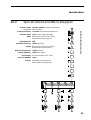
20.0
Specifications and Block Diagram
Frequency Response <±0.25dB, 15Hz-20kHz with filters out
Distortion (THD) <0.01%, 20Hz-20kHz @+10dBu
Inputs Electronically balanced & floating
(Transformer balanced option)
Input Impedance 10kΩ
Ω
Maximum Input Level +20dBu, balanced
Outputs Electronically balanced & floating
(Transformer balanced option)
Maximum Output Level +20dBu into 600Ω
Channel Separation >80dB, 20Hz-20kHz
Note: All Output bands are identical
Dynamic Range Typically >106dB, Analogue Input/Output,
unweighted 22Hz to 22kHz
Power Supply AC Mains 50/60Hz, 90V - 264V
Power Consumption <30VA
Options: Input balancing transformers
Output balancing transformers
45
Index
Index
A
Applications
5-Way Zoning Distribution
35
Dual Bi-amp
35
Mono 5-Way
36
Stereo 2-Way with a mono sub-bass
35
B
Backup
band gain
Block Diagram
Brightness
24
28
45
23
C
CD Horns
adding EQ
Clipboard
Clipping
input level
internal
Configuration
Contents
Contrast
Cut/Boost
EQ
38
24
12
13
18
3
23
31
D
Default screen
Default values
restoring
Delay
correction
input
output
Delay Link
output
Delete program
Down Key
18, 20
21
18
22
25
29
28
24
12
E
Edit LED
Encoder
EQ
adding a new EQ
Cut/Boost
frequency
lock extra
46
14
12
30
30
31
31
40, 41
shape
width
EQ screens
EQ shape
30
31
18
30
F
File Allocation Table
Frequency
EQ
Xover
Full range band
Fuse
39
31
27
37
15
G
Gain trim
Gain trims
storing
14
24
H
Headroom Management System 34
I
Input LED
Input meter
Inputs
delay
Installation
13
12
15
25
10
L
LED
input
mode
Limiter
threshold
Lock
OEM
owner
program
Lock extra EQ
Lock mode
Logo files
13
12
28
28
23, 41
23, 40
40
40, 41
40
39
M
Main Display
Mains fuse
Meter
input
output
12
9
12
14
Index
MIDI
connectors
details
dump
setting channel number
setting mode
Mode LED
Mono mode
Mute key
Mute LED
15
18
24
22
22
12
21
14
14
O
OEM Lock
Output
band gain
delay
Delay (Link)
delay link
EQ
Gain
High Xover freq
High Xover shape
Limiter
limiter
limiter threshold
Low Xover freq
Low Xover shape
name
Phase
polarity
source
Xover
Output meter
Output section
Outputs
41
28
29
19
28
19
19
27
27
19
28
28
27
27
19, 26
27
28
19, 26
19
14
14
15
P
Parameter wheel
PC Card
card types
formatting
slot
Phase
Compensation
Polarity
Power
AC Fusing
connection
inlet
Program files
12
39
24, 39
13
27
34
28
9
11
15
39
Q
Quick reference
adding EQ for CD Horns
Keeping relative delays
Making a band full range
Naming a band
Time aligning drivers
5
38
37
37
37
37
R
Rack space
requirements
Rear panel
Recall
key
Recalling
from a PC Card
RS-232 connections
10
15
32
12
5, 33
15
S
Safe mode
Screen layout
overview
Source
Specification
Stereo
2-Way mode
link
Store
key
to a PC Card
Swap
System security
Lock Mode
OEM Lock
Owner Lock
Program lock
Safe mode
42
16
26
45
21
18
32
12
33
24
40, 43
40
41
40
40
42
T
Temperature
22
U
Unpacking
Unsaved changes
UP key
Utilities
brightness
Configuration
Contrast
Delay Units
9
20
12
23
21
23
21, 22
47
Index
delete program
Format PC Card
Limit Units
Lock Out
menu
MIDI channel
MIDI dump
MIDI mode
OEM Lock
Owner Lock
Xover mode
24
24
22
22
18
22
24
22
23
23
23
V
Voltage setting
9
W
Warranty info
Width
EQ
Wiring convention
44
31
15
X
Xover
adjust
Output - High freq
Output - High shape
Output - Low freq
Output - Low shape
48
23
27
27
27
27
User Notes
49
User Notes
50
51
User Notes
52