1
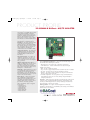
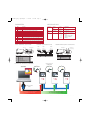
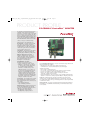
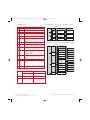
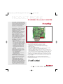
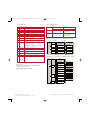
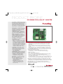
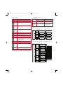
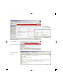
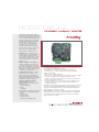
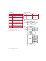
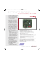
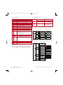
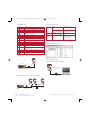
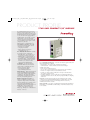
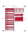
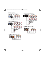
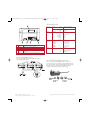
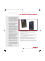
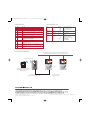
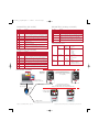
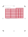
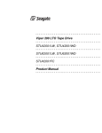
22Comm Cover_NL_8_23.qxd:Layout 1
8/30/06
3:50 PM
Page 1
PowerFlex
®
DSI™ COMMUNICATION ADAPTERS
BACnet® MS/TP ADAPTER (22-COMM-B)
ControlNet™ COAX ADAPTER (22-COMM-C)
DeviceNet™ ADAPTER (22-COMM-D)
EtherNet/IP™ ADAPTER (22-COMM-E)
LonWorks® ADAPTER (22-COMM-L)
PROFIBUS DP™ ADAPTER (22-COMM-P)
RS-232 DF1™ MODULE(22-SCM-232)
COMPACT I/O™ MODULE (1769-SM2)
DSI EXTERNAL COMMUNICATIONS KIT
DSI WIRELESS INTERFACE MODULE
1203-USB CONVERTER (1203-USB)
Communications
22Comm Cover_NL_8_23.qxd:Layout 1
8/25/06
12:23 PM
Page 2
22-COMM-B_10_4.qxd:Layout 1
10/4/06
1:08 PM
Page 1
PRODUCT PROFILE
22-COMM-B BACnet® MS/TP ADAPTER
The PowerFlex® 22-COMM-B adapter provides
an internal BACnet MS/TP connection to
PowerFlex 40 and 400 drives. It can also be
installed in a DSI External Communications
Kit for use with PowerFlex 4 drives. The
adapter provides a means to control, configure,
and collect data over a BACnet MS/TP network.
PRODUCT HIGHLIGHTS
Installation – The adapter mounts internal
to PowerFlex 40 and 400 drives to save
valuable panel space, and is field installable.
If an external connection is needed or when
using a PowerFlex 4 drive, the adapter can
also be installed in a DSI External
Communications Kit (22-XCOMM-DC-BASE).
Configuration Switches – The adapter has
configuration switches for setting the MAC
address (addressable up to node 127), and
enabling/disabling the termination and
bias resistors.
Supported Data Rates – The adapter can
“autoband” out-of-the-box or be set to one
of four selectable baud rates (9600, 19200,
38400 or 76800 bps), and can be configured
using a parameter.
Multiple Configuration Tool Options – A
number of configuration tools can be used to
configure the adapter and the connected
drive. These tools include the PowerFlex DSI
HIM, or drive-configuration software such as
DriveExplorer™ or DriveExecutive™.
DSI Routing – Allows DriveExplorer to connect
to a PowerFlex drive using a 22-SCM-232 or
1203-USB converter and then route over
BACnet MS/TP to access other Allen-Bradley®
drives. This eliminates the need for a separate
network connection and interface.
BACnet Objects – Unlike other PowerFlex
drive communication adapters, BACnet
MS/TP adapters use network objects to view
logic status, speed feedback and monitor
parameter values, and to send logic control,
speed reference and change parameter
values. The following objects are supported
by the adapter:
• Analog Input (AI)
• Analog Output (AO)
• Analog Value (AV)
• Binary Input (BI)
• Binary Output (BO)
• Binary Value (BV)
User Configurable Fault Responses – Selects the action that the adapter and
drive will take for the following two conditions:
• Idle Fault Action – the scanner is idle (controller in program mode)
• Comm Fault Action – network communications have become disrupted
Available actions include:
• Fault – the drive is faulted and stopped
• Stop – the drive is stopped using the current deceleration rate and is not faulted
• Zero Data – the adapter zeros the I/O data transmitted to the drive
• Hold Last – the adapter continues sending the I/O data prior to the fault and
the drive continues in its present state
• Send Fault Configuration – the user specifies the Logic Command, Reference,
and Datalink data that is sent to the drive, allowing complete flexibility in
configuring a fault action
Diagnostics – Built-in diagnostics allow drive-side troubleshooting of the network
connection using a PowerFlex DSI HIM, DriveExplorer or DriveExecutive. View
actual Logic Command/Speed Reference and Logic Status/Speed Feedback data
being transmitted to and from the controller.
Flash Upgradeable – The adapter can be flash updated in the field using
DriveExplorer, DriveExecutive or ControlFLASH to take advantage of new firmware
features as they become available.
22-COMM-B_10_4.qxd:Layout 1
10/4/06
1:08 PM
Page 2
PARAMETERS
SPECIFICATIONS
No.
01
02
Communications
03
04
05
06
07
08
09
10
11
12
Name
Description
Reset Module
Resets the adapter or sets the adapter parameters to factory default.
Comm Loss Action Sets the action that the adapter and drive will take if the adapter detects
a network failure.
Comm Loss Time Sets the communication loss timeout period (in seconds).
Flt Cfg Logic
Sets the data that is sent to the drive if Parameter 02 - [Comm Loss Action]
Flt Cfg Ref
is set to “Send Flt Cfg” and the adapter times out.
Baud Rate Cfg
Sets the baud rate (kilobits per second) at which the adapter communicates.
Baud Rate Act
Displays the baud rate (kilobits per second) actually used by the adapter.
MAC Address
Displays the actual address selected by the MAC address switches
SW1 – SW7 on the adapter.
Max Master
Sets the maximum MAC address for any device in the BACnet MS/TP token ring.
Max Info Frames Sets the maximum number of messages that the adapter can transmit while
it owns the token.
Device Inst Hi
Sets the high-priority portion of the device instance number used by the adapter.
Device Inst Lo
Sets the low-priority portion of the device instance number used by the adapter.
Drive
Electrical
Consumption
Regulatory
Mode Switch (SW8)
Reserved for future use
Node 1
LD B
+
SH
Node 2
-A
LD B
+
SH
Protocol
Data Rates
Protocol
Data Rate
Drive (DSI)
Network
BACnet
BACnet MS/TP
9600, 19200, 38400 or 76800 bps
DSI
19.2 Kbps
275 mA at 5 VDC
None
BTL (BACnet Testing Laboratories)
approval pending
UL508C
CAN/CSA C22.2 No. 14-M91
EN50178 and EN61800-3
EN61800-3
UL
cUL
CE
CTick
TERMINATION/BIAS SWITCHES
WIRING CONNECTIONS
MAC ADDRESS SWITCHES
MAC Address Switches
(SW1 - SW7)
Network
-BIAS Switch (SW2)
Node "n"
LD B
+
SH
-A
1 2 3 4
UP = 1 = OPEN
Description
Least Significant Bit (LSB) of MAC Address
Bit 1 of MAC Address
Bit 2 of MAC Address
Bit 3 of MAC Address
Bit 4 of MAC Address
Bit 4 of MAC Address
Most Significant Bit (MSB) of MAC Addres
Mode (reserved for future use)
RSRV Switch (SW4)
Reserved for future use
-A
1 2 3 4 5
6 7 8
Switches
SW1
SW2
SW3
SW4
SW5
SW6
SW7
SW8
+BIAS Switch (SW3)
TERM Switch (SW1)
Default
0
0
0
Node 0
0
0
0
0
—
—
NETWORK ROUTING EXAMPLE
Terminal
SHLD
B
A
Signal
Termination
Signal B
Signal A
Function
Shield Termination
TxRxD
TxRxD
UP = OFF
Switches
SW1
SW2
SW3
SW4
Description
Turns on/off the termination resistor
Turns on/off the -bias resistor
Turns on/off the +bias resistor
Reserved (not used)
Default
Up (Off)
Up (Off)
Up (Off)
—
PowerFlex 400 Drives with
22-COMM-B Adapters
PC Cable
Laptop or Desktop PC
with DriveExplorer
1203-USB or 22-SCM-232
Converter
BACnet MS/TP Network
Drive Cable
Use DriveExplorer Lite or Full to configure a single
drive and its installed BACnet adapter.
Publication 22COMM-PP001D-EN-P – July 2006
Use DriveExplorer Full to route through DSI and configure
drives connected directly on BACnet (Up to 127 drives!)
Copyright ©2006 Rockwell Automation, Inc. All Rights Reserved. Printed in USA.
22comm_C_PP_NL_8_23.qxd:Product_app_profile5-18-05.qxd
8/23/06
12:53 PM
Page 1
PRODUCT PROFILE
22-COMM-C ControlNet™ ADAPTER
The PowerFlex® DSI ControlNet adapter provides
redundant coaxial ControlNet connections for
PowerFlex 40 or PowerFlex 400 drives. The adapter
provides a means to control, configure, and collect
data over a ControlNet network. It can also be used
with other Allen-Bradley products that support a DSI
adapter, such as the DSI External Communications
Kit (22-XCOMM-DC-BASE), which enables PowerFlex
4 drives to connect to a ControlNet network.
Communications
PRODUCT HIGHLIGHTS
Internal Mount – The adapter mounts internal
to the drive to save panel space and is field
installable. PowerFlex 40 B frame drives require
an additional front cover 22B-CCB, PowerFlex 40
C frame drives require 22B-CCC, and PowerFlex
400 C frame drives require 22C-CCC.
Configuration – The adapter has rotary switches
for setting the node address and a jumper for
configuring Single or Multi-Drive operating modes.
Multiple Configuration Tool Options – A
number of configuration tools can be used to
configure the adapter and the connected drive.
These tools include the PowerFlex DSI HIM or
drive-configuration software such as
DriveExplorer™ or DriveExecutive™.
Single/Multi-Drive Operation –
The adapter can be used in two modes:
• Single - 1 network node consists of 1 drive.
• Multi-Drive - 1 network node can contain up
to 5 drives. In this cost-saving configuration,
the 22-COMM-C adapter is installed in a
PowerFlex 40 or 400 drive and up to four
additional PowerFlex 4, 40 or 400 drives can
be connected over their built-in RS-485 ports.
Each drive can be individually controlled,
configured, and monitored through the single
ControlNet connection. The adapter can also
be installed in a DSI External Communications
Kit using this operation mode to communicate
with up to 5 PowerFlex 4-Class drives.
I/O Messaging – I/O messaging is used to transfer
time-critical data, such as data that controls the
drive. The following data can be sent and received
by the adapter:
• Logic Status/Speed Feedback
• Logic Command/Speed Reference
Explicit Messaging – Explicit messaging involves
non time-critical information that is typically
triggered by the application (ladder program in a
controller, etc.). The adapter supports:
• Reading/writing of drive parameters
• Reading/writing of adapter parameters
User Configurable Fault Responses – Selects the action that the adapter and drive will
take for the following two conditions:
• Idle Fault Action - The scanner is idle (controller in program mode.)
• Comm Fault Action - Network communications have become disrupted.
Available actions include:
• Fault - The drive is faulted and stopped.
• Stop - The drive is stopped using the current deceleration rate and is not faulted.
• Zero Data - The adapter zeros the I/O data transmitted to the drive.
• Hold Last - The adapter continues sending the I/O data prior to the fault
and the drive continues in its present state.
• Send Fault Configuration - The user specifies the Logic Command and Speed Reference
data that is sent to the drive, allowing complete flexibility in configuring a fault action.
Diagnostics – Built-in diagnostics allow drive-side troubleshooting of the network
connection using a PowerFlex DSI HIM, DriveExplorer or DriveExecutive. View actual
Logic Status/Speed Feedback and Logic Command/Speed Reference data being transmitted
to and from the controller.
Flash Upgradeable – The adapter can be flash updated in the field using DriveExplorer,
DriveExecutive or ControlFLASH to take full advantage of new firmware features as they
become available.
22comm_C_PP_NL_8_23.qxd:Product_app_profile5-18-05.qxd
8/23/06
PARAMETERS
Description
01
Mode
Displays the Single or Multi-Drive operating mode selected with the
Operating Mode Jumper (J7) on the adapter.
02
CN Addr Cfg
Sets the ControlNet node address if the Node Address Switches are set
to “00”. (Updates Parameter 03 - [CN Addr Act] after a reset.)
03
CN Addr Act
Displays the ControlNet node address actually used by the adapter.
04
CN Rate Cfg
Sets the ControlNet data rate (megabits per second) at which the
adapter communicates. (Updates Parameter 05 - [CN Rate Act] after a reset.)
05
CN Rate Act
Displays the ControlNet data rate (megabits per second) actually used
by the adapter.
06
CN Active Cfg
Displays the source from which the adapter node address is taken. This
will be either switches or Parameter 02 - [CN Addr Cfg] in EEPROM. It is
determined by the settings of the Node Address Switches on the adapter.
If the Node Address Switches = “00” on power up, then Parameter 02 [CN Addr Cfg] is used to configure the adapter's ControlNet address.
07
Reset Module
Resets the adapter or sets parameter defaults settings.
08
Comm Flt Action
Sets the action that the adapter and drive will take if the adapter detects
that network communications have been disrupted. This setting is effective
only if I/O that controls the drive is transmitted through the adapter.
09
Idle Flt Action
Sets the action that the adapter and drive will take if the adapter detects
that the controller is in program mode. This setting is effective only if
I/O that controls the drive is transmitted through the adapter.
Flt Cfg Logic
11
Flt Cfg Ref
12
ControlNet
Sets the Logic Command or Speed Reference data that is sent
to the drive if any of the following is true:
– Parameter 08 - [Comm Flt Action] is set to “Send Flt Cfg” and
communications are disrupted.
– Parameter 09 - [Idle Flt Action] is set to “Send Flt Cfg” and the
controller is in program mode.
DSI I/O Cfg
Page 2
EXAMPLE I/O IMAGE - SINGLE MODE
No. Name
10
12:53 PM
Controller
Scanner
Adapter
Word and I/O
PowerFlex 40 Drive
Output
Image
(Write)
0 Logic Command
1 Reference
Logic Command
Reference
Input
Image
(Read)
0
1
2
3
Logic Status
Feedback
DSI I/O Act
Displays the drives that are active in the Multi-Drive mode.
14
Drv 0 Addr
15
Drv 1 Addr
Sets the corresponding node addresses of the daisy-chained drives when
the adapter Operating Mode Jumper (J7) is set for Multi-Drive operation.
16
Drv 2 Addr
17
Drv 3 Addr
18
Drv 4 Addr
19
Ref Adjust
ControlNet
Controller
Output
Image
(Write)
Sets the percent scale factor for the Speed Reference from the network.
Protocol
Data Rate
Drive
Protocol
Data Rate
Electrical
Consumption
Drive
Network
ControlNet
5 Mbps
DSI
0 Logic Command
1 Reference
PowerFlex Drive 0
2 Logic Command
3 Reference
PowerFlex Drive 1
4 Logic Command
5 Reference
PowerFlex Drive 2
6 Logic Command
7 Reference
PowerFlex Drive 3
8 Logic Command
9 Reference
PowerFlex Drive 4
0
1
2
3
Pad Word
Pad Word
Logic Status
Feedback
PowerFlex Drive 0
4 Logic Status
5 Feedback
PowerFlex Drive 1
6 Logic Status
7 Feedback
PowerFlex Drive 2
8 Logic Status
9 Feedback
PowerFlex Drive 3
10 Logic Status
11 Feedback
PowerFlex Drive 4
Message
Buffer
275 mA at 5 VDC
N/A
UL
UL508C
Compliance
cUL
CAN/CSA C22.2 No. 14-M91
CE
Message
Handler
Adapter
Word and I/O
19.2 Kbps
Regulatory
CTick
Message
Handler
DSI
Scanner
Input
Image
(Read)
Network
Message
Buffer
EXAMPLE I/O IMAGE - MULTI-DRIVE MODE
SPECIFICATIONS
Communications
Pad Word
Pad Word
Logic Status
Feedback
Message
Handler
Sets the configuration of the drives that are active in the Multi-Drive mode,
and identifies the DSI connections that would be attempted on a reset
or power cycle.
13
DSI
EN50178 and EN61800-3
AS/NZS 2064, Group 1, Class A
Publication 22COMM-PP001D-EN-P – July 2006
Supersedes Publication 22COMM-PP001C-EN-P – December 2005
Copyright ©2006 Rockwell Automation, Inc. All Rights Reserved. Printed in USA.
22comm_D_PP_NL_8_23.qxd:Product_app_profile5-18-05.qxd
8/25/06
12:06 PM
Page 1
PRODUCT PROFILE
22-COMM-D DeviceNet™ ADAPTER
The PowerFlex® 22-COMM-D adapter provides a
DeviceNet network connection for PowerFlex 40
AC drives and other DSI-based host devices with
an internal communications slot. The adapter
provides a means to control, configure and
collect data over a DeviceNet network.
Communications
PRODUCT HIGHLIGHTS
Internal Mount – The adapter mounts internal
to the drive to save panel space, and is field
installable. PowerFlex 40 drives require an
additional front cover (22B-CC*).
Configuration Switches – The adapter has
DIP switches for setting the node address (0-63),
data rate (125/250/500/Auto kbps), and a
jumper for Single/Multi-Drive modes.
Multiple Configuration Tool Options – A
number of configuration tools can be used to
configure the adapter and the connected drive.
These tools include the PowerFlex HIM, or
drive-configuration software such as
DriveExplorer™ or DriveExecutive™.
Single/Multi-Drive Operation – The adapter
can be used in two modes:
• Single – 1 network node consists of 1 drive.
• Multi-Drive – 1 network node can contain
up to 5 drives. In this cost-saving configuration,
the 22-COMM-D is installed in a PowerFlex 40
drive and up to four additional PowerFlex 4
or 40 drives can be connected over their
built-in RS-485 ports. Each drive can be
individually controlled, configured, and
monitored through the single DeviceNet
connection.
I/O Messaging – I/O messaging is used to
transfer time-critical data, such as data that
controls the drive. The following data can be
sent and received by the adapter:
• Logic Command/Reference
• Logic Status/Feedback
It supports Polled, Change-of-State(COS),
and Cyclic I/O methods.
Explicit Messaging – Explicit messaging
involves non time-critical information that is
typically triggered by the application (ladder
program in a controller, etc.). The adapter
supports:
• Reading/writing of drive parameters
• Reading/writing of adapter parameters
Automatic Device Replacement (ADR)
Support – Allows a scanner to upload and store
the adapter and drive configuration settings.
Upon replacing a faulty drive with a new unit,
the scanner can automatically download the
configuration data and set the node address.
User Configurable Fault Responses – Selects the action that
the adapter and drive will take for the following two conditions:
• Idle Fault Action – the scanner is idle (controller in program mode)
• Comm Fault Action – network communications have become disrupted
Available actions include:
• Fault – the drive is faulted and stopped
• Stop – the drive is stopped using the current deceleration rate and is not faulted
• Zero Data – the adapter zeros the I/O data transmitted to the drive
• Hold Last – the adapter continues sending the I/O data prior to the fault and the
drive continues in its present state
• Send Fault Configuration – the user specifies the Logic Command and Reference data
that is sent to the drive, allowing complete flexibility in configuring a fault action
Diagnostics – Built-in diagnostics allow drive-side troubleshooting of the network
connection using a PowerFlex DSI HIM, DriveExplorer or DriveExecutive. View actual
Logic Command/Reference and Logic Status/Feedback data being transmitted to and
from the controller.
Flash Upgradeable – The adapter can be flash updated in the field using
DriveExplorer, DriveExecutive or ControlFLASH to take advantage of new firmware
features as they become available.
22comm_D_PP_NL_8_23.qxd:Product_app_profile5-18-05.qxd
8/25/06
12:06 PM
Page 2
PARAMETERS
SPECIFICATIONS
No. Name
Description
Communications
01
Mode
Displays the mode selected by the jumper on the adapter (Single
or Multi-Drive).
02
DN Addr Cfg
Sets the DeviceNet node address after a reset or power cycle.
03
DN Addr Act
Displays the DeviceNet node address currently used by the adapter.
04
DN Rate Cfg
Sets the DeviceNet data rate after a reset or power cycle.
05
DN Rate Act
Displays the data rate actually used by the adapter.
06
Reset Module
Used to reset the adapter or set defaults.
07
Comm Flt Action
Sets the action that the adapter will take if it detects that
communications have been disrupted.
08
Idle Flt Action
Sets the action that the adapter will take if it detects that the scanner is idle.
09
DN Act Cfg
Displays the source from which the adapter node address and data
rate are taken.
10
Flt Cfg Logic
Sets the data that is sent to the drive if any of the following is true:
11
Flt Cfg Ref
• Parameter 07 - [Comm Flt Action] is set to Send Flt Cfg and
communications are disrupted.
COS Status Mask Sets the mask of the Logic Status word.
13
COS Fdbk Change Sets the hysteresis band to determine how much the Feedback can
change before it triggers a COS operation.
14
COS/Cyc Interval Displays the amount of time that a scanner will wait to check for data
in the adapter.
15
DSI I/O Config
Selects the I/O that is transferred through the adapter.
16
DSI I/O Act
Displays the I/O that the adapter is actively transmitting.
17
Drv 0 Addr
18
Drv 1 Addr
Sets the corresponding node addresses of the daisy-chained drives
used in Multi-Drive mode.
19
Drv 2 Addr
20
Drv 3 Addr
21
Drv 4 Addr
EDS FILES
The EDS files can be created on-line using RSNetWorx for
DeviceNet or downloaded from:
http://www.ab.com/drives/eds.html
Drive
Electrical
Consumption
Protocol
DeviceNet
125, 250, 500 Kbps or Autobaud
DSI
Drive (DSI)
150 mA at 5 VDC
Network
60 mA at 24 VDC
Regulatory
UL
Compliance
cUL
CAN/CSA C22.2 No. 14-M91
CE
EN50178 and EN61800-3
UL508C
EXAMPLE I/O IMAGE - SINGLE MODE
DSI
DeviceNet
Controller
Scanner
PowerFlex 40 Drive
Adapter
Word and I/O
Output
Image
(Write)
0 Logic Command
1 Reference
Logic Command
Reference
Input
Image
(Read)
0 Logic Status
1 Feedback
Logic Status
Feedback
Message
Handler
Message
Buffer
Message
Handler
EXAMPLE I/O IMAGE - MULTI-DRIVE MODE
DSI
DeviceNet
Controller
Scanner
Output
Image
(Write)
Input
Image
(Read)
Message
Handler
Publication 22COMM-PP001D-EN-P – July 2006
Supersedes Publication 22COMM-PP001C-EN-P – December 2005
Protocol
Data Rates
• Parameter 08 - [Idle Fault Action] is set to Send Flt Cfg and the
scanner is put into Program mode.
12
Network
Adapter
Word and I/O
0 Logic Command
1 Reference
PowerFlex Drive 0
2 Logic Command
3 Reference
PowerFlex Drive 1
4 Logic Command
5 Reference
PowerFlex Drive 2
6 Logic Command
7 Reference
PowerFlex Drive 3
8 Logic Command
9 Reference
PowerFlex Drive 4
0 Logic Status
1 Feedback
PowerFlex Drive 0
2 Logic Status
3 Feedback
PowerFlex Drive 1
4 Logic Status
5 Feedback
6 Logic Status
7 Feedback
PowerFlex Drive 2
8 Logic Status
9 Feedback
PowerFlex Drive 4
PowerFlex Drive 3
Message
Buffer
Copyright ©2006 Rockwell Automation, Inc. All Rights Reserved. Printed in USA.
22comm_E_PP_NL_8_23.qxd:Product_app_profile5-18-05.qxd
8/23/06
1:52 PM
Page 1
PRODUCT PROFILE
22-COMM-E EtherNet/IP™ ADAPTER
The PowerFlex® 22-COMM-E adapter provides an
EtherNet/IP network connection for PowerFlex
40 AC drives and other DSI-based host devices
with an internal communications slot. The
adapter provides a means to control, configure
and collect data over an EtherNet/IP network.
Communications
PRODUCT HIGHLIGHTS
Internal Mount – The adapter mounts internal
to the drive to save panel space, and is field
installable. PowerFlex 40 drives require an
additional front cover (22B-CC*).
Configuration Switches – The adapter has
DIP switches for enabling /disabling the web
pages and for setting Single/Multi-Drive modes.
Multiple Configuration Tool Options – A
number of configuration tools can be used to
configure the adapter and the connected drive.
These tools include the PowerFlex HIM, or
drive-configuration software such as
DriveExplorer™ or DriveExecutive™.
Single/Multi-Drive Operation – The adapter
can be used in two modes:
• Single – 1 network node consists of 1 drive.
• Multi-Drive – 1 network node can contain up
to 5 drives. In this cost-saving configuration,
the 22-COMM-E is installed in a PowerFlex 40
drive and up to four additional PowerFlex 4 or
40 drives can be connected over their built-in
RS-485 ports. Each drive can be individually
controlled, configured, and monitored
through the single EtherNet/IP connection.
I/O Messaging – I/O messaging is used to
transfer time-critical data, such as data that
controls the drive. The following data can be
sent and received by the adapter:
• Logic Command/Reference
• Logic Status/Feedback
Explicit Messaging – Explicit messaging involves
non time-critical information that is typically
triggered by the application (ladder program in
a controller, etc.). The adapter supports:
• Reading/writing of drive parameters
• Reading/writing of adapter parameters
Web Interface – Use a web browser such as
MicroSoft™ Internet Explorer™ to access the
drive over the Intranet or Internet.
• TCP/IP Configuration - View TCP/IP
configuration data and Ethernet
diagnostic information.
• Email Notification - Configure email
notification if a specific fault or alarm
occurs, if any fault or alarm occurs, or
if the drive is reset.
• DSI Device Browse - View every DSI device, including the drive and connected
peripherals. Provides general device information, diagnostics, and event/fault
queue display.
• Online User Manuals – Link to view the user manual online over the Internet.
• Software Tools Web Site – Link to the DriveExplorer and DriveExecutive Internet
web sites.
• Launch Drive Software Tools – Directly launch DriveExplorer or DriveExecutive
software already on your PC, and have the tool automatically connect to the drive.
User Configurable Fault Responses – Selects the action that the adapter and drive
will take for the following two conditions:
• Idle Fault Action – the scanner is idle (controller in program mode)
• Comm Fault Action – network communications have become disrupted
Available actions include:
• Fault – the drive is faulted and stopped
• Stop – the drive is stopped using the current deceleration rate and is not faulted
• Zero Data – the adapter zeros the I/O data transmitted to the drive
• Hold Last – the adapter continues sending the I/O data prior to the fault and the
drive continues in its present state
• Send Fault Configuration – the user specifies the Logic Command and Reference data
that is sent to the drive, allowing complete flexibility in configuring a fault action
Diagnostics – Built-in diagnostics allow drive-side troubleshooting of the network
connection using a PowerFlex DSI HIM, DriveExplorer or DriveExecutive. View actual Logic
Command/Reference and Logic Status/Feedback data being transmitted to and from the controller.
Flash Upgradeable – The adapter can be flash updated in the field using
DriveExplorer, DriveExecutive or ControlFLASH to take advantage of new firmware
features as they become available.
22comm_E_PP_NL_8_23.qxd:Product_app_profile5-18-05.qxd
8/23/06
PARAMETERS
No. Name
Description
01
Mode
Displays the mode selected by the jumper on the adapter
(Single or Multi-Drive).
02
BOOTP
Sets the DeviceNet node address after a reset or power cycle.
03
IP Addr Cfg 1
04
IP Addr Cfg 2
Sets the respective bytes in the IP address, where the represented
address is: Cfg1.Cfg2.Cfg3.Cfg4.
05
IP Addr Cfg 3
06
IP Addr Cfg 4
07
Subnet Cfg 1
08
Subnet Cfg 2
09
Subnet Cfg 3
10
Subnet Cfg 4
11
Gateway Cfg 1
12
Gateway Cfg 2
13
Gateway Cfg 3
14
Gateway Cfg 4
15
EN Rate Cfg
Configures the network data rate at which the adapter communicates.
16
EN Rate Act
Displays the data rate actually used by the adapter.
17
Reset Module
Used to reset the adapter or set defaults.
18
Comm Flt Action
Sets the action that the adapter will take if it detects that
communications have been disrupted.
19
Idle Flt Action
Sets the action that the adapter will take if it detects that the scanner is idle.
20
Flt Cfg Logic
21
Flt Cfg Ref
Sets the data that is sent to the drive if any of the following is true:
• Parameter 18 - [Comm Flt Action] is set to Send Flt Cfg and
communications are disrupted.
• Parameter 19 - [Idle Fault Action] is set to Send Flt Cfg and the
scanner is put into Program mode.
22
DSI I/O Config
Selects the I/O that is transferred through the adapter.
23
DSI I/O Act
Displays the I/O that the adapter is actively transmitting.
24
Drv 0 Addr
25
Drv 1 Addr
Sets the corresponding node addresses of the daisy-chained drives
used in Multi-Drive mode.
26
Drv 2 Addr
27
Drv 3 Addr
28
Drv 4 Addr
29
Web Enable
30
Web Features
1:52 PM
Page 2
SPECIFICATIONS
Communications
Network
Protocol
Data Rates
Drive
Electrical
Protocol
Consumption
Drive (DPI)
Network
EtherNet/IP
10/100 Mbps, Full/Half Duplex
DSI
350 mA at 5 VDC
N/A
Regulatory
UL
UL508C
Compliance
cUL
CAN/CSA C22.2 No. 14-M91
CE
EN50178 and EN61800-3
Sets the bytes of the subnet mask, where the represented mask
is :Cfg1.Cfg2.Cfg3.Cfg4.
EXAMPLE I/O IMAGE - SINGLE MODE
Sets the bytes of the gateway address, where the represented
address is: Cfg1.Cfg2.Cfg3.Cfg4.
EtherNet/IP
Controller
Displays the setting of the web pages switch on the adapter when the
adapter was last reset. (Enables/Disables using web pages)
Sets the access to the web interface and web configurable features.
Scanner
DSI
Adapter
Word and I/O
PowerFlex 40 Drive
Output
Image
(Write)
0 Logic Command
1 Reference
Logic Command
Reference
Input
Image
(Read)
0 Logic Status
1 Feedback
Logic Status
Feedback
Message
Handler
Message
Handler
Message
Buffer
EXAMPLE I/O IMAGE - MULTI-DRIVE MODE
EtherNet/IP
Controller
Scanner
Output
Image
(Write)
Input
Image
(Read)
Message
Handler
DSI
Adapter
Word and I/O
0 Logic Command
1 Reference
PowerFlex Drive 0
2 Logic Command
3 Reference
PowerFlex Drive 1
4 Logic Command
5 Reference
PowerFlex Drive 2
6 Logic Command
7 Reference
PowerFlex Drive 3
8 Logic Command
9 Reference
PowerFlex Drive 4
0 Logic Status
1 Feedback
PowerFlex Drive 0
2 Logic Status
3 Feedback
PowerFlex Drive 1
4 Logic Status
5 Feedback
PowerFlex Drive 2
6 Logic Status
7 Feedback
PowerFlex Drive 3
8 Logic Status
9 Feedback
PowerFlex Drive 4
Message
Buffer
22comm_E_PP_NL_8_23.qxd:Product_app_profile5-18-05.qxd
8/23/06
1:52 PM
Page 3
MAIN WEB PAGE
AUTO-REFRESH
PROCESS DISPLAY
AUTO-REFRESH
PROCESS DISPLAY
CONFIGURATION
EXAMPLE FAULT
NOTIFICATION
EMAIL
22comm_E_PP_NL_8_23.qxd:Product_app_profile5-18-05.qxd
Publication 22COMM-PP001D-EN-P – July 2006
Supersedes Publication 22COMM-PP001C-EN-P – December 2005
8/23/06
1:52 PM
Page 4
Copyright ©2006 Rockwell Automation, Inc. All Rights Reserved. Printed in USA.
PRODUCT PROFILE
22-COMM-L LonWorks® ADAPTER
The PowerFlex® DSI LonWorks™ adapter
provides an internal LonWorks connection for
PowerFlex 40 and PowerFlex 400 drives. It can
also be used with other Allen-Bradley products
that support a DSI adapter, such as the DSI
External Communications Kit (22-XCOMMDC-BASE) which enables PowerFlex 4
drives to connect to a LonWorks network.
(PowerFlex 4 drives cannot support an
internally-mounted adapter.) The adapter
provides a means to control, configure and
collect data over a LonWorks network.
Communications
PRODUCT HIGHLIGHTS
Internal Mount – The adapter mounts
internal to the drive to save panel space, and
is field installable. PowerFlex 40 B frame
drives require an additional front cover 22BCCB, PowerFlex 40 C frame drives require
22B-CCC and PowerFlex 400 C frame drives
require 22C-CCC.
Multiple Configuration Tool Options – A
number of configuration tools can be used
to configure the adapter and the connected
drive. These tools include the PowerFlex DSI
HIM, or drive-configuration software such as
DriveExplorer™ or DriveExecutive™ through a
22-SCM-232 or 1203-USB converter.
LonMark Functional Profile – “Variable
Speed Motor Drive: 6010” Support – The
adapter supports the standard functional
profile used by the HVAC industry for drives,
which provides a common set of system network
variables and configuration properties.
Additional “Manufacturer Defined”
Network Variables – Additional
“Manufacturer Defined” network variables
are also provided:
• Parameter Read/Write
• Metering
• Configuration
Resource Files – The following resource files
are included on 3.5” disk with the adapter:
• XIF File
• Type File (TYP)
• Format File (FMT)
• Language File (ENU)
• Functional Profile Template (FPT)
User Configurable Fault Responses – Selects the action that the adapter and
drive will take for the following two conditions:
• Idle Fault Action – the scanner is idle (controller in program mode)
• Comm Fault Action – network communications have become disrupted
Available actions include:
• Fault – the drive is faulted and stopped
• Stop – the drive is stopped using the current deceleration rate and is not faulted
• Zero Data – the adapter zeros the I/O data transmitted to the drive
• Hold Last – the adapter continues sending the I/O data prior to the fault and
the drive continues in its present state
• Send Fault Configuration – the user specifies the Logic Command and Speed
Reference data that is sent to the drive, allowing complete flexibility in
configuring a fault action
Diagnostics – Built-in diagnostics allow drive-side troubleshooting of the network
connection using a PowerFlex DSI HIM, DriveExplorer or DriveExecutive. View
actual Logic Command/Speed Reference and Logic Status/Speed Feedback data
being transmitted to and from the controller.
Flash Upgradeable – The adapter can be flash updated in the field using Thirdparty software tools such as Echelon® LonMaker™ for Windows or the LOADAPP
Neuron Chip Application Download Utility to take advantage of new firmware
features as they become available.
PARAMETERS
SPECIFICATIONS
No. Name
Description
Communications
01
Send Service Pin
Broadcasts a LON Service Pin message from the Neuron Chip to
provide the Neuron ID.
02
Neuron State
Displays the state of the Neuron Chip
03
Reset Module
Resets the adapter or sets the adapter parameters to factory default.
04
Neuron ID
Displays the Neuron Chip ID.
05
Clear Counters
Clears the network diagnostic counters.
06
Comm Flt Action
Sets the action that the adapter will take if it detects that network
communications have been disrupted.
07
Flt Cfg Logic
Sets the Logic Command data that is sent to the drive if Parameter 08
– [Comm Flt Action] is set to “Send Flt Cfg” and communications
are disrupted.
VARIABLE SPEED MOTOR DRIVE PROFILES
08
Flt Cfg Ref
Sets the Speed Reference data that is sent to the drive if Parameter 08
– [Comm Flt Action] is set to “Send Flt Cfg” and communications
are disrupted.
Node
Object
09
Idle Flt Action
Sets the action that the adapter and drive will take if the adapter detects
that the controller is in program mode. This setting is effective only if I/O
that controls the drive is transmitted through the adapter.
10
Idle Cfg Logic
Sets the Logic Command data that is sent to the drive if Parameter 09
– [Idle Flt Action] is set to “Send Flt Cfg” and the controller is in
program mode.
11
Idle Cfg Ref
Sets the Speed Reference data that is sent to the drive if Parameter 09
– [Idle Flt Action] is set to “Send Flt Cfg” and the controller is in
program mode.
12
RcvHrtBeat Time
Sets the time used as a Receive Heartbeat timer and triggers the
fault action in Parameter 06 – [Comm Flt Action].
Drive
Electrical
Consumption
The resource files can also be downloaded at:
http://www.ab.com/drives/22-comm/22-comm-l
Protocol
LonWorks
Data Rate
78 Kbps
Protocol
Drive (DSI)
Network
DSI
50 mA at 5 VDC
N/A
Regulatory
UL
UL508C
Compliance
cUL
CAN/CSA C22.2 No. 14-M91
CE
EN61800-6-4: 2001, EN61000-6-2: 2001
Node Object
nv 1
nviObjRequest
SNVT_obj_request
Mandatory
Network
Variables
nv 2
nvoObjStatus
SNVT_obj_status
Optional
Configuration Properties
nc 50 - nciLocation
Drive
Object
Variable Speed Motor
Drive: 6010
nv 1
RESOURCE FILES
Drive
nv 2
nviDrvSpeedStpt
SNVT_switch
nviDrvSpeedScale
SNVT_lev_percent
Mandatory
Network
Variables
Optional
Network
Variables
nv 3
nvoDrvSpeed
SNVT_lev_percent
nv 4
nvoDrvCurnt
SNVT_amp
nv 5
nvoDrvVolt
SNVT_volt
nv 6
nvoDrvPwr
SNVT_power_kilo
nv 7
nvoDrvRunHours
SNVT_time_hour
Configuration Properties
nc 50 - nciMaxSpeed (mandatory)
nc 53 - nciMinSpeed (mandatory)
nc 48 - nciRcvHrtBt (optional)
nc 49 - nciSndHrtBt (mandatory)
nc 52 - nciMinOutTm (optional)
nc 158 - nciNmlSpeed (mandatory)
nc 159 - nciNmlFreq (mandatory)
nc 160 - nciRampUpTm (mandatory)
nc 161 - nciRampDownTM (mandatory)
nc 162 - nciDrvSpeedScale (optional)
Manufacturer-Defined
Network Variables
nv 8
nvoDrvStatus
SNVT_state
nv 9
nvoDrvTemp
SNVT_temp_p
nv 10
nvoFreqAct
SNVT_freq_hz
nv 11
nvoDCBusVolt
SNVT_volt
nv 12
nvoDrvRunning
SNVT_switch
nv 13
nvoAnalogInput1
SNVT_lev_percent
nv 14
nvoAnalogInput2
SNVT_lev_percent
nv 15
nvoDigInput1
SNVT_switch
nv 16
nvoDigInput2
SNVT_switch
nv 17
nvoDrvFault
SNVT_count
nv 18
nvoGenRdData
SNVT_count
Manufacturer-Defined
Configuration Properties
nc 200 nciGenRdAdr
nc 200 nciGenWriAdr
nc 200 nciGenWriData
Publication 22COMM-PP001D-EN-P – July 2006
Supersedes Publication 22COMM-PP001C-EN-P – December 2005
Copyright ©2006 Rockwell Automation, Inc. All Rights Reserved. Printed in USA.
22comm_P_PP_NL_8_23.qxd:Product_app_profile5-18-05.qxd
8/23/06
2:55 PM
Page 1
PRODUCT PROFILE
22-COMM-P PROFIBUS DP™ ADAPTER
The PowerFlex® 22-COMM-P adapter provides
a PROFIBUS DP network connection for
PowerFlex 40 and 400 AC drives and other
DSI-based host devices with an internal
communications slot. The adapter provides a
means to control, configure and collect data
over a PROFIBUS DP network.
Communications
PRODUCT HIGHLIGHTS
Internal Mount – The adapter mounts
internal to the drive to save panel space, and
is field installable. PowerFlex 40 B frame
drives require 22B-CCB, PowerFlex 40 C
frame drives require 22B-CCC and PowerFlex
400 C frame drives require 22C-CCC.
Configuration Switches – The adapter has
DIP switches for setting the node address (1127), and jumpers for byte swapping (Intel or
Motorola format) and Single/Multi-Drive modes.
Multiple Configuration Tool Options – A
number of configuration tools can be used
to configure the adapter and the connected
drive. These tools include the PowerFlex
HIM, or drive configuration software such as
DriveExplorer™ or DriveExecutive™.
Single/Multi-Drive Operation – The
adapter can be used in two modes:
• Single – 1 network node consists of 1 drive.
• Multi-Drive – 1 network node can contain
up to 5 drives.
In this cost-saving configuration, the
22-COMM-P is installed in a PowerFlex 40
or 400 drive and up to four additional
PowerFlex 4, 40 or 400 drives can be
connected over their built-in RS-485 ports.
Each drive can be individually controlled,
configured, and monitored through the
single PROFIBUS DP connection.
I/O Messaging – I/O messaging is used to
transfer time-critical data, such as data that
controls the drive. The following data can be
sent and received by the adapter:
• Logic Command/Reference
• Logic Status/Feedback
It also supports synch and freeze modes.
Explicit Messaging – Explicit messaging
involves non time-critical information that
is typically triggered by the application
(ladder program in a controller, etc.).
The adapter supports:
• Reading/writing of drive parameters
• Reading/writing of adapter parameters
Compliance Tested – PNO compliance tested
User Configurable Fault Responses – Selects the action that
the adapter and drive will take for the following two conditions:
• Idle Fault Action – the scanner is idle (controller in program mode)
• Comm Fault Action – network communications have become disrupted
Available actions include:
• `Fault – the drive is faulted and stopped
• Stop – the drive is stopped using the current deceleration rate and is not faulted
• Zero Data – the adapter zeros the I/O data transmitted to the drive
• Hold Last – the adapter continues sending the I/O data prior to the fault and
the drive continues in its present state
• Send Fault Configuration – the user specifies the Logic Command and
Reference data that is sent to the drive, allowing complete flexibility in
configuring a fault action
Diagnostics – Built-in diagnostics allow drive-side troubleshooting of the network
connection using a PowerFlex DSI HIM, DriveExplorer or DriveExecutive. View
actual Logic Command/Reference and Logic Status/Feedback data being
transmitted to and from the controller.
Flash Upgradeable – The adapter can be flash updated in the field using
DriveExplorer, DriveExecutive or ControlFLASH to take advantage of new firmware
features as they become available.
22comm_P_PP_NL_8_23.qxd:Product_app_profile5-18-05.qxd
8/23/06
2:55 PM
Page 2
PARAMETERS
SPECIFICATIONS
No. Name
Description
Communications
01
Mode
Displays the mode selected by the J2 jumper (Single or Multi-Drive).
02
Reserved
03
Reserved
04
P-DP Addr Actual
Displays the node address actually used by the adapter.
05
P-DP Rate Actual
Displays the data rate actually used by the adapter.
06
Reserved
07
Reserved
08
Reset Module
Used to reset the adapter or set defaults.
09
Comm Flt Action
Sets the action that the adapter will take if it detects that
communications have been disrupted.
10
Idle Flt Action
Sets the action that the adapter will take if it detects that the scanner is idle.
11
DSI I/O Config
Selects the I/O that is transferred through the adapter.
12
DSI I/O Active
Displays the I/O that the adapter is actively transmitting.
13
Flt Cfg Logic
Sets the data that is sent to the drive if any of the following is true:
14
Flt Cfg Ref
• Parameter 09 - [Comm Flt Action] is set to Send Flt Cfg and
communications are disrupted.
Reserved
16
Reserved
17
Drv 0 Addr
18
Drv 1 Addr
19
Drv 2 Addr
20
Drv 3 Addr
21
Drv 4 Addr
22
Reserved
23
Reserved
24
P-DP State
Protocol
Data Rates
Drive
Electrical
Consumption
Protocol
Drive (DSI)
Network
PROFIBUS DP
9600 – 12 Mbps (autobauds)
DSI
370 mA at 5 VDC
N/A
Regulatory
UL
UL508C
Compliance
cUL
CAN/CSA C22.2 No. 14-M91
CE
EN50178 and EN61800-3
EXAMPLE I/O IMAGE - SINGLE MODE
DSI
Profibus
Controller
• Parameter 10 - [Idle Fault Action] is set to Send Flt Cfg and the
scanner is put into Program mode.
15
Network
Sets the corresponding node addresses of the daisy-chained drives
used in Multi-Drive mode.
Scanner
Adapter
Word and I/O
PowerFlex 40 Drive
Output
Image
(Write)
0 Logic Command
1 Reference
Logic Command
Reference
Input
Image
(Read)
0 Logic Status
1 Feedback
Logic Status
Feedback
Message
Handler
Message
Handler
Message
Buffer
EXAMPLE I/O IMAGE - MULTI-DRIVE MODE
DSI
Profibus
Displays the state of the PROFIBUS controller.
Controller
Scanner
Adapter
Word and I/O
GSD FILE
0 Logic Command
1 Reference
PF 40 Drive 0
The GSD file is provided on 3.5” disk with the adapter and can be
downloaded at: http://www.ab.com/drives/22-comm/22-comm-p
2 Logic Command
3 Reference
PF 4/40 Drive 0-1
4 Logic Command
5 Reference
PF 4/40 Drive 0-2
6 Logic Command
7 Reference
PF 4/40 Drive 0-3
8 Logic Command
9 Reference
PF 4/40 Drive 0-4
0 Logic Status
1 Feedback
PF 40 Drive 0
2 Logic Status
3 Feedback
PF 4/40 Drive 0-1
4 Logic Status
5 Feedback
6 Logic Status
7 Feedback
PF 4/40 Drive 0-2
8 Logic Status
9 Feedback
PF 4/40 Drive 0-4
Output
Image
(Write)
Input
Image
(Read)
Message
Handler
Publication 22COMM-PP001D-EN-P – July 2006
Supersedes Publication 22COMM-PP001C-EN-P – December 2005
PF 4/40 Drive 0-3
Message
Buffer
Copyright ©2006 Rockwell Automation, Inc. All Rights Reserved. Printed in USA.
22-SCM-232_PP_9_28.qxd:Product_app_profile5-18-05.qxd
9/28/06
7:37 AM
Page 1
PRODUCT PROFILE
22-SCM-232 RS-232 DF1™ MODULE
The PowerFlex® 22-SCM-232 provides an RS-232
DF1 connection for PowerFlex 4 and 40 AC
drives and other DSI-based host devices.
The module provides a means for drive
software tools, such as DriveExplorer™ and
DriveExecutive™, to communicate with drive
products. It also allows various Allen-Bradley®
controllers, from MicroLogix™ to ControlLogix®,
to control and read/write data to PowerFlex
4 and 40 AC drives.
Communications
PRODUCT HIGHLIGHTS
External Mount – The module connects
externally and is powered by the drive.
DSI Routing – Allows DriveExplorer to
connect to a PowerFlex 4 and 40 AC drive
using a 22-SCM-232 serial converter and
then route out over EtherNet/IP, DeviceNet,
or RS-485 to access other PowerFlex 4 and
40 AC drives (1-to-many connection). This
eliminates the need for a separate network
connection and interface.
DriveExplorer Lite Included –
A DriveExplorer Lite CD is included with the
22-SCM-232. DriveExplorer Lite is freeware
and can also be downloaded at:
http://www.ab.com/drives/driveexplorer/
free_download.html
Modbus RTU Master Support –
The module can also be configured to operate
as a Modbus RTU Master. The module converts
both the media (RS-232 to RS-485) and the
protocol (DF1 to Modbus RTU). Any Allen-Bradley
controller capable of originating and
receiving DF1 messages via its front port can
be used to control and read/write data on a
Modbus RTU network:
• MicroLogix 1000 (Series C or later discrete
controllers, and all analog controllers)
• MicroLogix 1200/1500
• SLC 5/03, 5/04, 5/05
• PLC-5
• ControlLogix, CompactLogix
Modbus RTU Pass-Thru Support – The module can also be configured to
operate as a RS-232 (DB-9) to RS-485 (RJ45) serial converter, where Modbus RTU
messages pass-thru both directions in the module.
Flash Upgradeable – The module can be flash updated in the field using
DriveExplorer, DriveExecutive or ControlFLASH to take advantage of new firmware
features as they become available. The module is also the primary connection
mechanism for flashing drives and other peripherals.
ACCESSORIES
Do you have a PC with only a USB connection? Use a USB to Serial adapter, such
as an Allen-Bradley 9300-USBS, to connect to the RS-232 side of the 22-SCM-232.
The adapter is a small, portable unit with no AC power required. It has also been
tested with Allen-Bradley DriveExplorer and DriveExecutive software tools.
Do you want to connect to a drive without having to open the enclosure door?
Use a GracePort™ interface, such as a P-A20-B3RX (Nema 4/12 interface) or
P-A20-F3RO (Nema 4/12 interface with AC outlet), available from Grace
Engineered Products Inc. (http://www.grace-eng.com).
22-SCM-232_PP_11_1.qxd:Product_app_profile5-18-05.qxd
11/1/06
11:31 AM
Page 2
PARAMETERS
SPECIFICATIONS
No. Name
Description
Communications
01
Sets the operation of the serial converter (Auto, Master, Slave,
RTU Master, and RTU Pass-thru).
Adapter Cfg
02
DF1 Addr Cfg
Configures the DF1 address used for the serial converter.
03
DF1 Rate Cfg
Configures the data rate used for the serial port.
04
Comm Flt Action
Sets the action that the module will take if it detects that
communications have been disrupted.
05
Reset Module
Used to reset the adapter or reset defaults.
06
Clear DF1 Counts
Used to clear the DF1 statistical parameters (7-15).
07
DF1 Packets Sent Displays the number of DF1 packets sent by the serial converter.
08
DF1 Packets Rcvd Displays the number of DF1 packets received by the serial converter.
09
Undelivered Msgs Displays the number of DF1 packets sent by the serial converter and
not acknowledged.
Network
Protocol
NRS-232: DF1, Modbus RTU
RS-485: DSI, Modbus RTU
Data Rates
Drive
Electrical
Consumption
9600 – 38,400 bps
Protocol
DSI, Modbus RTU
Data Rates
19.2 Kbps
Drive (DSI)
170mA at 5V DC
Network
10
ENQs Sent
Displays the number of ENQs sent by the serial converter.
11
ENQs Received
Displays the number of ENQs received by the serial converter.
12
NAKs Received
Displays the number of NAKs received by the serial converter.
13
NAK Bad Packet
Displays the number of NAKs received by the serial converter because
of bad packets.
14
NAK No Memory
Displays the number of NAKs received by the serial converter because
of insufficient buffer memory.
15
Duplicate Msgs
Displays the number of duplicate messages sent by the serial converter.
16
DF1 Addr Actual
Displays the actual DF1 address used by the serial converter.
17
DF1 Rate Actual
Displays the actual data rate used by the serial converter.
N/A
Regulatory
UL
Compliance
cUL
UL508C
CAN/CSA C22.2 No. 14-M91
CE
EN50178 and EN61800-3
CTick
AS/NZS 2064, Group 1, Class A
DRIVEEXPLORER LITE
POINT-TO-POINT SYSTEM EXAMPLE
SOFTWARE TOOL
CONNECTION EXAMPLE
Controller
RS232
DF1
RS485
Modbus RTU
PowerFlex 4-Class Drive
or other DSI Host
22-SCM-232
Serial Converter
MULTIPLE-DRIVE SYSTEM EXAMPLE
Drive #1
Drive #2
Controller
RS232
DF1
RS485
Modbus RTU
22-SCM-232
Serial Converter
AK-UO-RJ45-SC1
Splitter Cable
Publication 22COMM-PP001D-EN-P – July 2006
Supersedes Publication 22COMM-PP001C-EN-P – December 2005
22-SCM-232
DriveExplorer
or
DriveExecutive
PC
Drive #3
AK-UO-RJ45-TB2P
Terminal Blocks
1/4W, 120 Ω
Terminating Resistors
(on first and last drives)
Copyright ©2006 Rockwell Automation, Inc. All Rights Reserved. Printed in USA.
1769-SM2_PP_NL_9_28.qxd:Product_app_profile5-18-05.qxd
9/28/06
7:39 AM
Page 1
PRODUCT PROFILE
1769-SM2 COMPACT I/O™ MODULE
The 1769-SM2 module provides a direct 1769
platform connection for PowerFlex® 4, 40, and
400 AC drives, other DSI-based host devices, and
Modbus RTU-based host devices such as PowerFlex
70, 700, and 700S AC drives equipped with 20COMM-H adapters. The 1769-SM2 can be used
with MicroLogix™ 1500 and CompactLogix™
controllers, and remote 1769-based nodes such
as the 1769-ADN DeviceNet™ adapter to control,
configure, and collect data.
Communications
PRODUCT HIGHLIGHTS
1769 Platform Connectivity – The module
can be used in 1769-based systems, such as:
• MicroLogix 1500 controllers
• CompactLogix controllers
• Remote 1769-based node adapters
(1769-ADN DeviceNet, etc.)
Three DSI/Modbus RTU Channels – 3 channels
are provided and can be configured for:
• Single-Drive Mode – One PowerFlex 4, 40 or
400 AC drive per channel (3 drives total)
• Multi-Drive Mode – Up to five PowerFlex 4, 40
or 400 AC drives per channel (15 drives total)
• Modbus RTU Master – Connect Modbus RTU
Slave devices, including 3rd Party devices and
PowerFlex 70, 700, and 700S AC drives
equipped with 20-COMM-H adapters
I/O Messaging – I/O messaging is used to
transfer time-critical data, such as data that
controls the drive. The following data can be
sent and received by the adapter:
• Logic Status/Speed Feedback
• Logic Command/Speed Reference
Explicit Messaging – Explicit messaging involves
non time-critical information that is typically
triggered by the application (ladder program in
a controller, etc.). The adapter supports the
reading/writing of parameters, etc. in the drive
and to any connected DSI peripheral(s).
Multiple Configuration Tool Options – A
number of configuration tools can be used to
configure the adapter and the connected drive.
When the 1769-SM2 is set to “Parameter” mode,
tools like the PowerFlex DSI HIM, or driveconfiguration software such as DriveExplorer™ or
DriveExecutive™ can be used. When set to
“Controller” mode, software tools such as
RSLogix 500™, RSLogix 5000™ or RSNetWorx for
DeviceNet™ can be used.
User Configurable Fault Responses – Selects the action that the adapter and drive will
take for the following two conditions:
• Idle Fault Action – the scanner is idle (controller in program mode)
• Comm Fault Action – network communications have become disrupted
Available actions include:
• Fault – the drive is faulted and stopped
• Stop – the drive is stopped using the current deceleration rate and is not faulted
• Zero Data – the adapter zeros the I/O data transmitted to the drive
• Hold Last – the adapter continues sending the I/O data prior to the fault and the
drive continues in its present state
• Send Fault Configuration – the user specifies the Logic Command, Speed Reference,
and Datalink data that is sent to the drive, allowing complete flexibility in configuring
a fault action
Diagnostics – Built-in diagnostics allow drive-side troubleshooting of the network
connection using a PowerFlex DSI HIM, DriveExplorer or DriveExecutive. View actual
Logic Status/Speed Feedback and Logic Command/Speed Reference data being
transmitted to and from the controller.
Flash Upgradeable – The adapter can be flash updated in the field using DriveExplorer,
DriveExecutive or ControlFLASH to take full advantage of new firmware features as they
become available.
1769-SM2_PP_NL_9_28.qxd:Product_app_profile5-18-05.qxd
9/28/06
PARAMETERS
No.
Name
Description
01
Config Mode
Displays the module’s configuration mode.
02
DSI Mode
Displays the module’s operating mode (single or multi-drive).
03
Reset Module
Used to reset the module or set defaults.
04
Idle Action 1
Sets the action that the module and CH1 drive take if the module
detects that the controller was switched to Program mode or Test mode.
05
Flt Cfg Logic 1
06
Flt Cfg Ref 1
Sets the data that is sent to the CH1 drive if Parameter 04 - [Idle Action 1]
is set to “Send Flt Cfg” and the controller is put into Program or Test mode.
07
DSI I/O Cfg 1
Sets the configuration of the CH1 drives that are active in the Multi-drive mode.
08
DSI I/O Act 1
Displays the CH1 drives that are active in the Multi-drive mode.
09
Drv 0 Addr 1
10
Drv 1 Addr 1
Sets the corresponding node addresses of the daisy- chained CH1 drives when
the module Operating Mode Switch (SW2) is set for Multi-drive operation.
11
Drv 2 Addr 1
12
Drv 3 Addr 1
13
Drv 4 Addr 1
14
RTU Baud Rate 1
Sets the baud rate used by the CH1 drives when the module is operating in the
Multi-drive mode and Parameter 07 - [DSI I/O Cfg 1] is set to “RTU Master”.
15
RTU Parity 1
Sets the parity used by the CH1 drives when the module is operating in the
Multi-drive mode and Parameter 07 - [DSI I/O Cfg 1] is set to “RTU Master”.
16
RTU Rx Delay 1
Sets the inter-character delay used by the CH1 drives to detect the end
of a receive packet when the module is operating in the Multi-drive
mode and Parameter 07 - [DSI I/O Cfg 1] is set to “RTU Master”.
7:39 AM
Page 2
SPECIFICATIONS
Communications
Network
Protocol
Data Rates
DSI/Modbus RTU
DSI: 19.2 Kbps
Modbus RTU: 300 - 38400 bps
Electrical
Consumption
Module
350 mA at 5 VDC
Channel
0 mA at 24 VDC (supplied by
Compact I/O power supply)
Regulatory
UL
UL508C
Compliance
cUL
CAN/CSA C22.2 No. 14-M91
CE
EN50081-2 and EN61000-6-2
CTick
AS/NZS 2064, 1997, Group 1, Class A
EXAMPLE I/O IMAGE
Single-Drive Mode
Output Image
Module Control Word
Logic Command
Speed Reference
17
RTU Tx Delay 1
Sets the inter-frame delay used by the CH1 drives to delay the sending of
a transmit packet when the module is operating in the Multi-drive mode
and Parameter 07 - [DSI I/O Cfg 1] is set to “RTU Master”.
18
RTU MsgTimeout 1
Sets the amount of time in seconds that the module will wait for a
response from a Modbus RTU CH1 slave when the module is operating in the
Multi-drive mode and Parameter 07 - [DSI I/O Cfg 1] is set to “RTU Master”.
19
Idle Action 2
Sets the action that the module and CH2 drive take if the module detects
that the controller was switched to Program mode or Test mode.
20
Flt Cfg Logic 2
21
Flt Cfg Ref 2
Sets the data that is sent to the CH2 drive if Parameter 19 - [Idle Action 2]
is set to “Send Flt Cfg” and the controller is put into Program or Test mode.
22
DSI I/O Cfg 2
Sets the configuration of the CH2 drives that are active in the Multi-drive mode.
23
DSI I/O Act 2
Displays the CH2 drives that are active in the Multi-drive mode.
24
Drv 0 Addr 2
25
Drv 1 Addr 2
Sets the corresponding node addresses of the daisy- chained CH2 drives when
the module Operating Mode Switch (SW2) is set for Multi-drive operation.
26
Drv 2 Addr 2
27
Drv 3 Addr 2
28
Drv 4 Addr 2
29
RTU Baud Rate 2
Sets the baud rate used by the CH2 drives when the module is operating in the
Multi-drive mode and Parameter 22 - [DSI I/O Cfg 2] is set to “RTU Master”.
Drive 3
30
RTU Parity 2
Sets the parity used by the CH2 drives when the module is operating in the
Multi-drive mode and Parameter 22 - [DSI I/O Cfg 2] is set to “RTU Master”.
Drive 4
31
RTU Rx Delay 2
Sets the inter-character delay used by the CH2 drives to detect the end of a
receive packet when the module is operating in the Multi-drive mode and
Parameter 22 - [DSI I/O Cfg 2] is set to “RTU Master”.
32
RTU Tx Delay 2
Sets the inter-frame delay used by the CH2 drives to delay the sending of a
transmit packet when the module is operating in the Multi-drive mode and
Parameter 22 - [DSI I/O Cfg 2] is set to “RTU Master”.
33
RTU MsgTimeout 2
Sets the amount of time in seconds that the module will wait for a response
from a Modbus RTU CH2 slave when the module is operating in the Multi-drive
mode and Parameter 22 - [DSI I/O Cfg 2] is set to “RTU Master”.
34
Idle Action 3
Sets the action that the module and CH3 drive take if the module detects
that the controller was switched to Program mode or Test mode.
35
Flt Cfg Logic 3
36
Flt Cfg Ref 3
Sets the data that is sent to the CH3 drive if Parameter 34 - [Idle Action 3] is set
to “Send Flt Cfg” and the controller is put into Program or Test mode.
37
DSI I/O Cfg 3
Sets the configuration of the CH3 drives that are active in the Multi-drive mode.
38
DSI I/O Act 3
Displays the CH3 drives that are active in the Multi-drive mode.
39
Drv 0 Addr 3
40
Drv 1 Addr 3
Sets the corresponding node addresses of the daisy-chained CH3 drives when the module
Operating Mode Switch (SW2) is set for Multi-drive operation.
41
Drv 2 Addr 3
42
Drv 3 Addr 3
43
Drv 4 Addr 3
44
RTU Baud Rate 3
Sets the baud rate used by the CH3 drives when the module is operating in the
Multi-drive mode and Parameter 37 - [DSI I/O Cfg 3] is set to “RTU Master”.
45
RTU Parity 3
Sets the parity used by the CH3 drives when the module is operating in the
Multi-drive mode and Parameter 37 - [DSI I/O Cfg 3] is set to “RTU Master”.
46
RTU Rx Delay 3
Sets the inter-character delay used by the CH3 drives to detect the end of a
receive packet when the module is operating in the Multi-drive mode and
Parameter 37 - [DSI I/O Cfg 3] is set to “RTU Master”.
47
RTU Tx Delay 3
Sets the inter-frame delay used by the CH3 drives to delay the sending of a
transmit packet when the module is operating in the Multi-drive mode and
Parameter 37 - [DSI I/O Cfg 3] is set to “RTU Master”.
48
RTU MsgTimeout 3
Sets the amount of time in seconds that the module will wait for a response
from a Modbus RTU CH3 slave when the module is operating in the Multi-drive
mode and Parameter 37 - [DSI I/O Cfg 3] is set to “RTU Master”.
Input Image
Module Status Word
Logic Status
Speed Feedback
Word
CH2
0
3
4
CH1
1
2
CH3
5
6
Multi-Drive Mode
Drive 0
Drive 1
Drive 2
Output Image
Input Image
Module Control Word
Logic Command
Speed Reference
Logic Command
Speed Reference
Logic Command
Speed Reference
Logic Command
Speed Reference
Logic Command
Speed Reference
Module Status Word
Logic Status
Speed Feedback
Logic Status
Speed Feedback
Logic Status
Speed Feedback
Logic Status
Speed Feedback
Logic Status
Speed Feedback
CH1
1
2
3
4
5
6
7
8
9
10
Word
CH2
0
11
12
13
14
15
16
17
18
19
20
CH3
21
22
23
24
25
26
27
28
29
30
1769-SM2_PP_NL_10_4.qxd:Product_app_profile5-18-05.qxd
10/4/06
1:10 PM
Page 3
EXAMPLE SYSTEMS
RUN RUN
PORT
MOD
NET A
NET B
0.00 Hz
2.5 Cans/Sec
646.0 Bus/Volt
STS
RUN RUN
PORT
MOD
NET A
NET B
0.00 Hz
2.5 Cans/Sec
646.0 Bus/Volt
STS
RUN RUN
1769-SM2_PP_NL_9_28.qxd:Product_app_profile5-18-05.qxd
Publication 22COMM-PP001D-EN-P – July 2006
Supersedes Publication 22COMM-PP001C-EN-P – December 2005
9/28/06
7:39 AM
Page 4
Copyright ©2006 Rockwell Automation, Inc. All Rights Reserved. Printed in USA.
22comm_Xdcbase_PP_NL_9_28.qxd:Product_app_profile5-18-05.qxd
9/28/06
7:41 AM
Page 1
PRODUCT PROFILE
DSI EXTERNAL COMMUNICATIONS KIT
The DSI External Communications Kit
(22-XCOMM-DC-BASE) provides a network
connection for PowerFlex® 4, 40, and 400 AC
drives. Each kit can serve up to 5 drives via
their RS-485 ports.
Communications
PRODUCT HIGHLIGHTS
Multiple Network Connectivity – Provides
a network connection for DSI-based
PowerFlex 4, 40, and 400 AC drives. Each
drive connected to a kit can be
independently controlled, and have its
parameters accessed either through explicit
messaging, or by using software tools such
as DriveExplorer™ or DriveExecutive™.
The kit is for use with only the following
Allen-Bradley communication adapters
(sold separately):
• 22-COMM-B BACnet® MS/TP
• 22-COMM-C ControlNet®
• 22-COMM-E EtherNet/IP™
• 22-COMM-D DeviceNet™
• 22-COMM-L LonWorks®
• 22-COMM-P PROFIBUS DP™
Universal Mounting – Direct panel, DIN
rail, even Zero-Stacking™ (side-by-side)
mounting is possible using the all-aluminum,
EMI noise-immune enclosure.
Versatile Power Connections – Connect
either a 24 VDC power supply to the kit's
convenient removable terminal block, or
use the Allen-Bradley AC power adapter
(20-XCOMM-AC-PS1, sold separately) that
comes with interchangeable region plugs
(US, UK, Europe, and Australia). The kit can
also be daisy-chained to provide power for
additional kits.
EXAMPLE SYSTEM OVERVIEW
ControlLogix
Controller
PanelView Plus
1500
Computer with
Ethernet Connection
Ethernet Network
PORT
MOD
NET A
NET B
PowerFlex 40 Drive with
22-COMM-E Adapter in
Single-Drive Mode
PowerFlex 40 Drive with 22-COMM-E Adapter
in Multi-Drive Mode Connected to
Four PowerFlex 4/40/400 Drives
External DSI Communications Kit with 22-COMM-E Adapter
in Multi-Drive Mode connected to
Five PowerFlex 4/40/400 Drives
22comm_Xdcbase_PP_NL_9_28.qxd:Product_app_profile5-18-05.qxd
9/28/06
7:41 AM
Page 2
SPECIFICATIONS
Communications
Network
Drive
Protocol
Dependent on installed adapter
Data Rate
Dependent on installed adapter
Protocol
Data Rate
Electrical
Consumption
Network
DSI
19.2 Kbps
Drive
None
EtherNet/IP
None
DeviceNet
PROFIBUS DP
60 mA at 24 VDC
None
BACnet MS/TP
None
LonWorks
None
ControlNet
None
DC Power Supply
22-COMM-B
75 mA at 24 VDC
Requirement
22-COMM-C
110 mA at 24 VDC
22-COMM-D
60 mA at 24 VDC
22-COMM-E
140 mA at 24 VDC
22-COMM-L
60 mA at 24 VDC
Item
Connector
Description
❶
Network
Network connection for communication adapter
➋
24 VDC
Connection for 24 VDC power source
➌
AC-to-DC
Connection for 20-XCOMM-AC-PS1 power adapter
cUL
CAN/CSA C22.2 No. 14-M91
➍
DSI
DSI connection for 22-RJ45CBL-C** cable or AK-U0-RJ45-TB2P terminal
block adapter
CE
EN50178 and EN61800-3
➎
Serial
Connection for 1203-SFC cable to use with PC software tools
22-COMM-P
Compliance
60 mA at 24 VDC
UL
CTick
UL508C
EN61800-3
DAISY-CHAINING KITS
You can power additional external communication kits by
daisy-chaining them together.
AC POWER ADAPTER OPTION
The AC power adapter (20-XCOMM-AC-PS1) is an accessory
AC-to-DC converter for use with the external communications kit.
The converter, which comes with interchangeable plugs, is shown
below. The converter connects to any available 100-240 VAC
receptacle. Use the appropriate plug for your region:
Publication 22COMM-PP001D-EN-P – July 2006
Supersedes Publication 22COMM-PP001C-EN-P – December 2005
Copyright ©2006 Rockwell Automation, Inc. All Rights Reserved. Printed in USA.
DSI WIM_22Comm PP_9_28:Layout 1
9/28/06
7:54 AM
Page 1
PRODUCT PROFILE
DSI WIRELESS INTERFACE MODULE
The DSI Wireless Interface Module (WIM)
provides a wireless communication interface
between a Pocket PC, laptop computer or
desktop computer equipped with Bluetooth®
wireless technology, and any Allen-Bradley®
product supporting the DSI™ protocol.
Connectivity includes the entire PowerFlex®
4-Class Family of drives and peripherals.
PRODUCT HIGHLIGHTS
Multiple Enclosure Styles – The DSI WIM
is offered in two different form-factors to
meet your environment needs:
• NEMA 1 (cat. no. 22-WIM-N1)
• NEMA 4 (cat. no. 22-WIM-N4S)
Versatile Mounting – The NEMA 1 DSI
WIM (shown letf) can be installed in a NEMA
1 DSI HIM bezel (22-HIM-B1) mounted on
the front of an enclosure door. However, if a
DSI HIM is still required and already
occupies DSI Port 2 on the drive, a DSI
splitter cable (AK-U0-RJ45-SC1) can be used.
The NEMA 4 DSI WIM (shown right) is
designed for NEMA 4 and permanentmount applications.
Multiple Tool Options – A number of tools
can be used to configure and communicate
with the DSI WIM and connected drive.
These tools include the PowerFlex DSI HIM,
or drive-configuration software such as
Pocket DriveExplorer™ for Pocket PC,
DriveExplorer™ or DriveExecutive™.
DSI Routing – Connect point-to-point to a
PowerFlex 4-Class drive using the DSI WIM,
and then route out over DSI through the
built-in RS-485 ports to access other drives
on the network (up to 31 drives!). This
eliminates the need for a separate network
connection and interface.
Security – Use the security mode parameter
to enable or disable access and the security
PIN parameter to set a unique 4-digit pass
code number. Together, these parameters
prevent “others” from gaining access to
parameters in the WIM and connected drive
for configuration.
User Configurable Fault Response – Selects the action that the DSI WIM and
drive will take for the following condition:
• Comm Fault Action – network communications have become disrupted
Available actions include:
• Fault – the drive is faulted and stopped
• Stop – the drive is stopped using the current deceleration rate and is not faulted
• Zero Data – the WIM zeros the I/O data transmitted to the drive
• Hold Last – the WIM continues sending the I/O data prior to the fault and the
drive continues in its present state
Diagnostics – Built-in diagnostics allow drive-side troubleshooting of the network
connection using Pocket DriveExplorer for Pocket PC, DriveExplorer or
DriveExecutive. View actual Logic Command/Speed Reference and Logic
Status/Speed Feedback data being transmitted to and from the controller.
Flash Upgradeable – The DSI WIM can be used to flash update its own firmware,
and the firmware of other connected DSI peripherals such as 22-COMM-* adapters
through Pocket DriveExplorer for Pocket PC, DriveExplorer or DriveExecutive to
take full advantage of new firmware features as they become available.
DSI WIM_22Comm PP_10_4:Layout 1
11/1/06
9:53 AM
Page 2
PARAMETERS
SPECIFICATIONS
No.
01
02
03
Radio
04
05
06
07
08
09
10
11
Name
Adapter Cfg
Adapter Type
Drive Addr Cfg
Description
Sets the operating mode of the WIM.
Displays the present operating mode of the WIM.
Sets the node address of the WIM for use with the WIM operating mode set
with Parameter 01 - [Adapter Cfg].
Drive Addr Act
Displays the node address of the drive that the WIM is communicating with
when the WIM is to RTU Master mode using Parameter 01 - [Adapter Cfg].
Security Mode
Enables/disables the security mode for the WIM, which prevents accessing its
parameters and the connected drive for configuration.
Security PIN
Sets the PIN number to access WIM parameters for configuration when
Parameter 03 - [Security Mode] is set to 1 = PIN Required.
Comm Flt Action Sets the action that the WIM and drive will take if the WIM detects that wireless
communications are disrupted. This setting is effective only if I/O that controls
the drive is transmitted through the WIM.
Reset Module
Resets the adapter or sets parameter defaults.
Clear DF1 Counts Resets the DF1 statistical parameters 10 and 11 to 0 if set to “1 = Clear
Counts.” This parameter will be reset to “0 = Ready” after a “Clear Counts”
command has been performed.
DF1 Packets Sent Displays the number of DF1 packets sent by the WIM. This parameter is
normally about equal to the value in parameter 11.
DF1 Packets Rcvd Displays the number of DF1 packets received by the WIM. This parameter is
normally about equal to the value in parameter 10.
NETWORK EXAMPLE
Communications
Drive
Electrical
Consumption
Regulatory
Compliance
Transceiver
Frequency
Power
Range
Protocol
Data Rate
Drive (DSI)
Network
UL
cUL
CE
CTick
FCC ID
IC
Bluetooth v1.1 Compliant
2.4 GHz Frequency Hopping
2.5 mW Maximum RF Output
Class II - 10 m (32.8 ft)
DSI
19.2 Kbps
170 mA at 5 VDC
None
UL508C
CAN/CSA C22.2 No. 14-M91
EN50178 and EN61800-3
AS/NZS 2064, Group 1, Class A
SNT-2XWIMNX
5450A-2XWIMNX
Route through DSI and configure drives connected directly on
BACnet MS/TP (22-COMM-B), ControlNet (22-COMM-C), DeviceNet (22-COMM-D) or
EtherNet/IP (22-COMM-E) in "Master" mode, or Modbus in "RTU Master" mode
Bluetooth Wireless Technology
Allen-Bradley
PowerFlex 70
© 2000
PORT
MOD
NET A
NET B
STS
Bluetooth-enabled Pocket PC (shown) with
Pocket DriveExplorer, or Laptop or Desktop PC
with DriveExplorer Full
22-HIM-B1 HIM Bezel with
22-WIM-N1 DSI Wireless Interface Module
Publication 22COMM-PP001D-EN-P – July 2006
Supersedes Publication 22COMM-PP001C-EN-P – December 2005
PowerFlex 40 Drives with
22-COMM-* Adapters
Copyright ©2006 Rockwell Automation, Inc. All Rights Reserved. Printed in USA.
1203-USB_9_28.qxd:Layout 1
9/28/06
7:56 AM
Page 1
PRODUCT PROFILE
1203-USB UNIVERSAL SERIAL BUS™ CONVERTER
The 1203-USB Converter provides direct USB
connectivity to PowerFlex® 70 (SC or EC), 700
(SC or VC), 700H and 700S drives, PowerFlex
4, 40, 40P and 400 drives, and other DPIbased or DSI-based host devices all-in-one
product (combines 1203-SSS & 22-SCM-232
technology). It can also be used with legacy
SCANport-based host devices such as Bulletin
1336 PLUS II and 1305 drives. The converter
provides a means for drive software tools, such
as DriveExplorer™ and DriveTools SP™ (which
includes DriveExecutive™ and DriveObserver™),
to communicate with drive products.
PRODUCT HIGHLIGHTS
External Connection – The converter
connects externally and is powered by the
connected drive. No additional power source
is required.
DPI Routing Support – When connected to
a PowerFlex Architecture-Class drive, use
DriveExplorer with a 1203-USB converter to
route over EtherNet/IP™, ControlNet™,
DeviceNet™, or RS-485 DF1 to access other
Allen-Bradley drives (1-to-many connection).
This eliminates the need for a separate
network connection and interface.
DSI Routing Support – When connected to
a PowerFlex Component-Class drive, use
DriveExplorer with a 1203-USB converter to
route over EtherNet/IP™, ControlNet™, or
DeviceNet™ to access other Allen-Bradley
drives (1-to-many connection). Like the 22SCM-232 module, the converter also has an
RTU Master mode. This mode provides
connectivity for up to 31 drives via their builtin RS-485 ports. This eliminates the need for
a separate network connection and interface.
Legacy SCANport Connectivity – Use the
1203-USB converter with DriveExplorer or
DriveTools SP (DriveExecutive and
DriveObserver) to connect with 1305 and
1336 PLUS II drives, and other SCANportbased host products.
DriveExplorer Lite/USB Drivers Included – A CD with DriveExplorer Lite and USB
drivers is included with the 1203-USB converter. DriveExplorer Lite is freeware and can
also be downloaded at: http://www.ab.com/drives/driveexplorer/free_download.html
Flash Upgradeable – The 1203-USB converter can be flash updated in the field
using DriveExplorer, DriveExecutive or ControlFLASH to take advantage of new
firmware features as they become available. The converter is also the primary
connection mechanism for flashing drives and other peripherals.
ACCESSORIES
Do you want to connect to a drive without having to open the enclosure door?
The following GracePort™ interface options provide this capability:
DPI/SCANport Products
• P-A19-B3 (NEMA 4/12 interface with 8-pin mini-DIN connector)
• P-A19-F3R0 (same as above plus convenience AC outlet)
DSI Products
• P-A20-B3 (NEMA 4/12 interface with RJ45 connector)
• P-A20-F3R0 (same as above plus convenience AC outlet)
For more information about these and other related products, please visit
Grace Engineered Products Inc. at http://www.grace-eng.com
1203-USB_9_28.qxd:Layout 1
9/28/06
7:56 AM
Page 2
PARAMETERS (DPI MODE)
PARAMETERS (SCANport MODE)
No.
01
02
03
No.
01
02
03
04
05
06
07
08
09
Name
DPI Port
Reset Module
Clear DF1 Counts
Description
Displays the port on the host drive which the converter is connected.
Resets the converter or sets the converter parameters to factory default.
Resets the DF1 statistical Parameter 04 - [DF1 Packets Sent] and Parameter
05 - [DF1 Packets Rcvd] to 0 if set to “1 = Clear Counts”. This parameter will
be reset to “0 = Ready” after a “Clear Counts” command has been performed.
DF1 Packets Sent Displays the number of DF1 packets sent by the converter. This parameter is normally
about equal to the value in Parameter 05 - [DF1 Packets Rcvd].
DF1 Packets Rcvd Displays the number of DF1 packets received by the converter. This parameter
is normally about equal to the value in Parameter 04 - [DF1 Packets Sent].
Interface Mode Selects whether the converter will autodetect DPI or SCANport devices and use
the appropriate protocol.
DPI Data Rate
Displays the data rate used by the DPI drive. This data rate is set in the drive,
and the converter autobauds to it.
Ref/Fdbk Size Displays the size of the Speed Reference/Feedback words which is determined
by the drive. The converter automatically uses the correct size.
Datalink Size
Displays the size of each Datalink word which is determined by the drive.
The converter automatically uses the correct size.
Name
Adapter Port
Reset Module
Clear DF1 Counts
Description
Displays the port on the host drive which the converter is connected.
Resets the converter or sets the converter parameters to factory default.
Resets the DF1 statistical Parameter 04 - [DF1 Packets Sent] and Parameter
05 - [DF1 Packets Rcvd] to 0 if set to “1 = Clear Counts”. This parameter will
be reset to “0 = Ready” after a “Clear Counts” command has been performed.
DF1 Packets Sent Displays the number of DF1 packets sent by the converter. This parameter is
normally about equal to the value in Parameter 05 - [DF1 Packets Rcvd].
DF1 Packets Rcvd Displays the number of DF1 packets received by the converter. This parameter
is normally about equal to the value in Parameter 04 - [DF1 Packets Sent].
RTU DSI Addr Cfg Selects whether the converter will autodetect DPI or SCANport devices and use the
appropriate protocol.
04
05
06
SPECIFICATIONS
Communications
Network
Drive
PARAMETERS (DSI MODE)
No.
01
02
03
Name
Adapter
Reset Module
Clear DF1 Counts
04
DF1 Packets Sent
05
DF1 Packets Rcvd
06
RTU DSI Addr Cfg
07
RTU DSI Addr Act
08
Adapter Type
Description
Cfg Sets the operating mode of the converter.
Resets the converter or sets the converter parameters to factory default.
Resets the DF1 statistical Parameter 04 - [DF1 Packets Sent] and Parameter
05 - [DF1 Packets Rcvd] to 0 if set to “1 = Clear Counts”. This parameter will
be reset to “0 = Ready” after a “Clear Counts” command has been performed.
Displays the number of DF1 packets sent by the converter. This parameter is
normally about equal to the value in Parameter 05 - [DF1 Packets Rcvd].
Displays the number of DF1 packets received by the converter. This parameter
is normally about equal to the valu in Parameter 0 - [DF1 Packets Sent].
Sets the node address of the converter for use with the converter operating mode set
with Parameter 01 - [Adapter Cfg].
Displays the node address of the drive that the converter is communicating with
when the converter is set to RTU Master mode using Parameter 01 - [Adapter Cfg].
Displays the present operating mode of the converter.
Electrical
Consumption
Regulatory
Compliance
Protocol
Data Rate
Protocol
Data Rate
Drive
Network
UL
cUL
CE
CTick
USB
115.2 Kbps
DPI
125 or 500 Kbps
DSI
19.2 Kbps
SCANport
125 Kbps
DPI/SCANport
130 mA at 12 VDC
DSI
170 mA at 5 VDC
None
UL508C
CAN/CSA C22.2 No. 14-M91
EN50178 and EN61800-3
AS/NZS 2064, Group 1, Class A
NETWORK EXAMPLE
PowerFlex 70 Drives
with 20-COMM-*
Adapters (Port 5)
PORT
MOD
NET A
NET B
Route through DPI to drives connected on
BACnet MS/TP (20-COMM-BControlNet (20-COMM-C),
DeviceNet (20-COMM-D), EtherNet/IP (20-COMM-E)
or DF1 (20-COMM-S)
0.00 Hz
2.5 Cans/Sec
646.0 Bus/Volt
PORT
MOD
NET A
NET B
STS
0.00 Hz
2.5 Cans/Sec
646.0 Bus/Volt
STS
Laptop or Desktop PC
with DriveExplorer or DriveExecutive
20-HIM-H10 (included)
USB Cable (included)
1203-USB
Converter
Route through DSI to drives connected on
ControlNet (22-COMM-C), DeviceNet (22-COMM-D) or
EtherNet/IP (22-COMM-E) in "Master" mode, or Modbus in "RTU Master" mode
PowerFlex 40 Drives with
22-COMM-* Adapters
22-HIM-H10 (included)
Publication 22COMM-PP001D-EN-P – July 2006
Copyright ©2006 Rockwell Automation, Inc. All Rights Reserved. Printed in USA.
22Comm Cover_NL_11_1.qxd:Layout 1
11/1/06
9:51 AM
Page 3
4-CLASS CONNECTIVITY
PowerFlex 4-Class
Communication
Adapter / Module
Protocol
4
40
400
(internal)
Modbus RTU
std.
std.
std.
22-COMM-B
BACnet MS/TP
Y(1)
Y
Y
22-SCM-232
DF1
Y
Y
Y
22-COMM-C
ControlNet
Y(1)
Y
Y
22-COMM-D
DeviceNet
Y(1)
Y
Y
22-COMM-E
EtherNet/IP
Y(1)
Y
Y
22-COMM-L
LonWorks
Y(1)
Y
Y
22-COMM-P
PROFIBUS DP
Y(1)
Y
Y
1769-SM2
DSI Modbus RTU
Y
Y
Y
22-WIM-Nx
Bluetooth
Y
Y
Y
1203-USB
Universal Serial Bus
Y
Y
Y
Note: (1) Requires use with either a PowerFlex 40 or 400 and installed communication adapter configured for Multi-Drive mode,
or a DSI External Communications Kit.
22Comm Cover_NL_11_1.qxd:Layout 1
11/1/06
9:47 AM
Page 4
PowerFlex is a registered trademark of Rockwell Automation. DriveExplorer, DPI, DriveExecutive, Remote I/O, and Compact I/O are trademarks of Rockwell Automation.
Trademarks not belonging to Rockwell Automation are property of their respective companies.
Publication 22COMM-PP001D-EN-P – July 2006
Supersedes Publication 22COMM-PP001C-EN-P – December 2005
Copyright ©2006 Rockwell Automation, Inc. All Rights Reserved. Printed in USA.