1
AXIS 370 Cobra
User's manual
IBM 3270 Protocol Converter
AXIS 370
Preface
Preface
Welcome to the AXIS 370 Cobra coax 3270 protocol converter. This
manual will guide you through a step-by-step installation procedure.
Once installed, the AXIS 370 Cobra works without operator
intervention.
About Axis
Axis Communications is dedicated to provide inventive solutions for
network connection of computer peripherals. Since the start in 1984,
it has been one of the fastest growing companies in the market. The
headquarters are located in Lund, Sweden, with subsidiaries in
Boston, Tokyo, and Hong Kong.
Axis Communications has a distributor network operating in more
than 50 countries world-wide, marketing three product lines:
•
IBM Mainframe and S/3x
These products include a wide range of plug-in interfaces and
stand-alone products such as the Cobra+ protocol converters and
the AXIS AFP IPDS-to-PostScript converter.
•
Network Print Servers
These intelligent Ethernet and Token Ring print servers support a
wide range of LAN protocols. The AXIS 530, AXIS 560 and
AXIS 570 are Ethernet print servers, and the AXIS 630, AXIS
660 and AXIS 670 are Token Ring print servers. The AXIS 150 is
an Ethernet print server dedicated to PC networks.
•
CD-ROM Servers
The latest addition to the Axis product range, these CD-ROM
servers allow CD-ROM data to be shared over the network. The
product range includes the AXIS 850 and AXIS 851 Ethernet
CD-ROM servers as well as the AXIS 950 and AXIS 951 Token
Ring CD-ROM servers.
ii
AXIS 370 Cobra User’s Manual
Preface
AXIS 370
About this manual
The manual applies to the AXIS 370 Cobra with software release 1.00
and to subsequent releases until otherwise notified.
Please refer to the AX-7 Cobra+ Technical Reference Manual for
further information of functions and parameters.
The manual consists of five sections:
1. INTRODUCTION – The AXIS 370 Cobra and the concepts
used in this manual.
2. INSTALLATION – Connecting your AXIS 370 Cobra to the
printer and the IBM system.
3. CONFIGURATION – How to configure your AXIS 370 Cobra
from a terminal.
4. ADVANCED FUNCTIONS – How to use your printer beyond
standard IBM operation.
5. SOLVING PROBLEMS – Checklist for identifying and solving
problems.
Every care has been taken in the preparation of this manual; if you
detect any inaccuracies or omissions, please inform us at the address
on the back cover.
Axis Communications AB cannot be held responsible for any
technical or typographical errors and reserves the right to make
changes in this manual and to the firmware without prior notice.
AXIS 370 Cobra User’s Manual
Part No: 14368
Revision: 1.0
Dated: January, 1996
Copyright © Axis Communications AB, 1996
AXIS 370 Cobra User’s Manual
iii
AXIS 370
Preface
Emission Notices
USA
Europe
This equipment generates, uses, and can radiate radio frequency
energy and if not installed and used in accordance with the instruction
manual, may cause interference to radio communications. It has been
tested and found to comply with the limits for a Class A computing
device pursuant to Subpart B of Part 15 of FCC rules, which are
designed to provide reasonable protection against such interference
when operated in a commercial environment. Operation of this
equipment in a residential area is likely to cause interference in which
case the user at his own expense will be required to take whatever
measures may be required to correct the interference. Shielded cables
should be used with this unit to ensure compliance with the Class A
limits.
This digital equipment fulfils the requirements for radiated emission
according to limit B of EN55022/1987, and the requirements for
immunity according to EN50082-1/1992 residential, commercial,
and light industry. (Compliance is not valid for unshielded network
and printer cables.)
Trademark Acknowledgements
IBM, Epson, Fujitsu, Hewlett Packard, LaserJet and Xerox, are
registered trademarks of the respective holders.
iv
AXIS 370 Cobra User’s Manual
Table of Contents
Table of Contents
Section 1
Introduction . . . . . . . . . . . . . . . . . . . . . . . . . . . . . . . . . . . . . . . . . . . . . . . . . . . . . . . 9
The AXIS 370 Cobra . . . . . . . . . . . . . . . . . . . . . . . . . . . . . . . . . . . . . . . . . . . 9
Theory of Operation . . . . . . . . . . . . . . . . . . . . . . . . . . . . . . . . . . . . . . . . . . . 9
ASCII Printer Driver . . . . . . . . . . . . . . . . . . . . . . . . . . . . . . . . . . . . . . . . . . . 10
IBM Printer Emulation . . . . . . . . . . . . . . . . . . . . . . . . . . . . . . . . . . . . . . . . . 10
Section 2
Installation . . . . . . . . . . . . . . . . . . . . . . . . . . . . . . . . . . . . . . . . . . . . . . . . . . . . . . .
Unpacking . . . . . . . . . . . . . . . . . . . . . . . . . . . . . . . . . . . . . . . . . . . . . . . . . . .
Printer Attachment . . . . . . . . . . . . . . . . . . . . . . . . . . . . . . . . . . . . . . . . . . . .
System Attachment . . . . . . . . . . . . . . . . . . . . . . . . . . . . . . . . . . . . . . . . . . .
11
11
12
14
Section 3
Configuration . . . . . . . . . . . . . . . . . . . . . . . . . . . . . . . . . . . . . . . . . . . . . . . . . . . . .
Configuration from a Terminal . . . . . . . . . . . . . . . . . . . . . . . . . . . . . . . . . .
Key Definitions . . . . . . . . . . . . . . . . . . . . . . . . . . . . . . . . . . . . . . . . . . . . . . .
Basic Configuration . . . . . . . . . . . . . . . . . . . . . . . . . . . . . . . . . . . . . . . . . . . .
Select Printer Driver . . . . . . . . . . . . . . . . . . . . . . . . . . . . . . . . . . . . .
Select IBM Printer Emulation . . . . . . . . . . . . . . . . . . . . . . . . . . . . . .
Select System Language . . . . . . . . . . . . . . . . . . . . . . . . . . . . . . . . . .
Select Form Length . . . . . . . . . . . . . . . . . . . . . . . . . . . . . . . . . . . . . .
Select Lines per Inch (LPI) . . . . . . . . . . . . . . . . . . . . . . . . . . . . . . . .
Select Characters per Inch (CPI) . . . . . . . . . . . . . . . . . . . . . . . . . . .
Save the Configuration . . . . . . . . . . . . . . . . . . . . . . . . . . . . . . . . . . . . . . . . .
Exit the Configuration . . . . . . . . . . . . . . . . . . . . . . . . . . . . . . . . . . . . . . . . .
15
16
17
18
19
20
21
22
23
24
25
26
Section 4
Advanced Functions . . . . . . . . . . . . . . . . . . . . . . . . . . . . . . . . . . . . . . . . . . . . . . .
Extended Emulation Mode . . . . . . . . . . . . . . . . . . . . . . . . . . . . . . . . . . . . .
Main Menu . . . . . . . . . . . . . . . . . . . . . . . . . . . . . . . . . . . . . . . . . . . . . . . . . . .
Configuration from the System . . . . . . . . . . . . . . . . . . . . . . . . . . . . . . . . . .
Transparency . . . . . . . . . . . . . . . . . . . . . . . . . . . . . . . . . . . . . . . . . . . . . . . . .
Redefine Configuration and Transparency Sequences . . . . . . . . . . . . . . .
27
27
28
29
30
31
AXIS 370 Cobra User’s Manual
v
Table of Contents
Edit Translation Tables . . . . . . . . . . . . . . . . . . . . . . . . . . . . . . . . . . . . . . . . .
Character Translation . . . . . . . . . . . . . . . . . . . . . . . . . . . . . . . . . . . .
Editing Translation Tables using a Terminal . . . . . . . . . . . . . . . . . .
Editing Translation Tables using the System . . . . . . . . . . . . . . . . . .
User Definable Strings . . . . . . . . . . . . . . . . . . . . . . . . . . . . . . . . . . . . . . . . .
Programming Strings from a Terminal . . . . . . . . . . . . . . . . . . . . . .
Programming Strings from the System . . . . . . . . . . . . . . . . . . . . . .
Using the Strings . . . . . . . . . . . . . . . . . . . . . . . . . . . . . . . . . . . . . . . .
String Substitutions . . . . . . . . . . . . . . . . . . . . . . . . . . . . . . . . . . . . . . . . . . . .
Programming String Substitutions from a Terminal . . . . . . . . . . . .
Programming String Substitutions from the System . . . . . . . . . . .
Bar Codes . . . . . . . . . . . . . . . . . . . . . . . . . . . . . . . . . . . . . . . . . . . . . . . . . . .
Define Bar Codes . . . . . . . . . . . . . . . . . . . . . . . . . . . . . . . . . . . . . . .
Print Bar Code . . . . . . . . . . . . . . . . . . . . . . . . . . . . . . . . . . . . . . . . . .
Automatic Page Orientation . . . . . . . . . . . . . . . . . . . . . . . . . . . . . . . . . . . .
32
32
33
37
38
38
40
40
41
42
43
44
44
45
46
Section 5
Solving Problems . . . . . . . . . . . . . . . . . . . . . . . . . . . . . . . . . . . . . . . . . . . . . . . . . .
Missing Printouts . . . . . . . . . . . . . . . . . . . . . . . . . . . . . . . . . . . . . . . . . . . . . .
Incorrect Host Printouts . . . . . . . . . . . . . . . . . . . . . . . . . . . . . . . . . . . . . . .
Some Characters are Printed Incorrectly . . . . . . . . . . . . . . . . . . . .
Corrupted Printouts . . . . . . . . . . . . . . . . . . . . . . . . . . . . . . . . . . . . .
Incorrect Page Breaks . . . . . . . . . . . . . . . . . . . . . . . . . . . . . . . . . . . .
Lost characters at end of line . . . . . . . . . . . . . . . . . . . . . . . . . . . . . .
Additional empty lines or spaces . . . . . . . . . . . . . . . . . . . . . . . . . . .
Reporting Problems . . . . . . . . . . . . . . . . . . . . . . . . . . . . . . . . . . . . . . . . . . .
Printing the Parameter List . . . . . . . . . . . . . . . . . . . . . . . . . . . . . . . .
Producing Hexdumps . . . . . . . . . . . . . . . . . . . . . . . . . . . . . . . . . . . .
Error messages . . . . . . . . . . . . . . . . . . . . . . . . . . . . . . . . . . . . . . . . . . . . . . .
47
47
48
48
48
48
49
49
50
50
51
52
Appendix A
The Parameter List . . . . . . . . . . . . . . . . . . . . . . . . . . . . . . . . . . . . . . . . . . . . . . . .
Printout Example . . . . . . . . . . . . . . . . . . . . . . . . . . . . . . . . . . . . . . . . . . . . .
Printer Drivers . . . . . . . . . . . . . . . . . . . . . . . . . . . . . . . . . . . . . . . . . . . . . . . .
Parameter Descriptions . . . . . . . . . . . . . . . . . . . . . . . . . . . . . . . . . . . . . . . .
53
53
54
54
Appendix B
DBC Character Table . . . . . . . . . . . . . . . . . . . . . . . . . . . . . . . . . . . . . . . . . . . . . 65
vi
AXIS 370 Cobra User’s Manual
Table of Contents
Appendix C
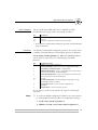
The Front Panel . . . . . . . . . . . . . . . . . . . . . . . . . . . . . . . . . . . . . . . . . . . . . . . . . . .
The POWER indicator . . . . . . . . . . . . . . . . . . . . . . . . . . . . . . . . . . . . . . . . .
The SYSTEM indicator . . . . . . . . . . . . . . . . . . . . . . . . . . . . . . . . . . . . . . . . .
The Rotary Switch . . . . . . . . . . . . . . . . . . . . . . . . . . . . . . . . . . . . . . . . . . . .
Start Conditions . . . . . . . . . . . . . . . . . . . . . . . . . . . . . . . . . . . . . . . . .
Test Mode . . . . . . . . . . . . . . . . . . . . . . . . . . . . . . . . . . . . . . . . . . . . .
66
66
66
66
67
67
Appendix D
Updating the Software . . . . . . . . . . . . . . . . . . . . . . . . . . . . . . . . . . . . . . . . . . . . .
Software that can be Updated . . . . . . . . . . . . . . . . . . . . . . . . . . . . .
Checking if an update is available . . . . . . . . . . . . . . . . . . . . . . . . . .
Updating the AXIS 370 Cobra Flash ROM . . . . . . . . . . . . . . . . . .
68
68
68
68
Appendix E
Technical Specification . . . . . . . . . . . . . . . . . . . . . . . . . . . . . . . . . . . . . . . . . . . . .
Host Environments . . . . . . . . . . . . . . . . . . . . . . . . . . . . . . . . . . . . . .
IBM System Features . . . . . . . . . . . . . . . . . . . . . . . . . . . . . . . . . . . . .
Axis 370 Cobra Additional Features . . . . . . . . . . . . . . . . . . . . . . . .
Hardware Specifications . . . . . . . . . . . . . . . . . . . . . . . . . . . . . . . . . .
Approvals . . . . . . . . . . . . . . . . . . . . . . . . . . . . . . . . . . . . . . . . . . . . . .
Environments . . . . . . . . . . . . . . . . . . . . . . . . . . . . . . . . . . . . . . . . . . .
69
69
69
70
70
70
70
Appendix F
Related Documentation . . . . . . . . . . . . . . . . . . . . . . . . . . . . . . . . . . . . . . . . . . . . 71
Index
AXIS 370 Cobra User’s Manual
72
vii
Table of Contents
This page is intentionally left blank
viii
AXIS 370 Cobra User’s Manual
Section 1: Introduction
AXIS 370
Section 1 Introduction
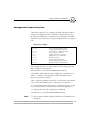
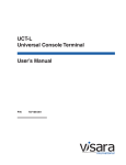
The AXIS 370 Cobra
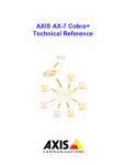
The AXIS 370 Cobra is a protocol converter, which makes it possible
to connect a PC type printer to an IBM mainframe environment.
The AXIS 370 Cobra has a coax connector for incoming system data
and a parallel Centronics connector for outgoing ASCII data. Power is
supplied via the printer's connector or from an optional external
power supply.
Rotary Switch
POWER Indicator
SYSTEM Indicator
FRONT
901
456
23
78
Printer Connector
POWER
SYSTEM
System Connector
BACK
External Power
Supply Connector
SYSTEM
PS-A
AXIS 370 Cobra front and back panels.
Theory of Operation
Print data from an IBM host is in a format that cannot be recognized
by PC type printers.
The AXIS 370 Cobra converts IBM control and character codes to
ASCII control commands and characters, which are recognizable by
the PC type printer.
Together, the AXIS 370 Cobra and the attached printer will appear to
the IBM host as an original IBM coax printer.
AXIS 370 Cobra User’s Manual
9
AXIS 370
Section 1: Introduction
ASCII Printer Driver
The AXIS 370 Cobra can utilize many of the functions resident in the
attached printer, such as bolding, page formatting and paper source
selections. The control commands for these functions reside in the
Printer Drivers. These cover the standard ASCII emulations such as
IBM Proprinter, Epson and HP LaserJet. See Appendix A for a list of
available Printer Drivers.
IBM Printer Emulation
The following IBM printers can be emulated by the AXIS 370 Cobra
and an attached PC type printer:
•
IBM 3287 mod. 1 and 2C (default)
•
IBM 3268 mod. 1 and 2
•
IBM 4214 mod. 1
•
IBM 3262
•
IBM 4224 mod. 2 (non-IPDS mode)
•
IBM 4230 mod. 201
See Appendix E for further technical specification.
10
AXIS 370 Cobra User’s Manual
Section 2: Installation
Section 2 Installation
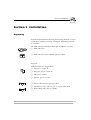
Unpacking
Unpack and check all the items using the following check list. Contact
your dealer if anything is missing or damaged. All packing materials
are recyclable.
The AXIS 370 Cobra Hardware Pack (part no: 0052-1) contains:
❏ AXIS 370 Cobra
❏ AXIS 370 Cobra User’s Manual, part no: 14368
Optional:
AXIS External Power Supply PS-A:
❏ US, part no: 12919 or
❏ European, part no: 13599 or
❏ UK, part no: 12866
❏ Japanese, part no: 13249
❏ Printer cable extension, part no: 13522
❏ Self-adhesive Velcro ribbons, part no: 13539 and 13540
❏ Flash loading cable, part no: 14510
AXIS 370 Cobra User’s Manual
11
Section 2: Installation
Printer Attachment
First you establish contact between the AXIS 370 Cobra and the PC
type printer. Prepare this by checking that the printer is ready to use.
You may also need an optional external power supply, if the printer is
unable to supply the AXIS 370 Cobra.
1. Switch off the printer.
2. Connect the AXIS 370 Cobra to the printer, either directly to
the parallel printer port, or using the optional printer cable
extension and Velcro ribbons.
3. Set the rotary switch to position ‘9’ (test printout function).
4. Switch on the printer.
5. Connect the optional external power supply (if needed).
The POWER indicator (green) is lit and the SYSTEM indicator
(green) will flash for a few seconds.
If the POWER indicator is not lit, the printer is unable to supply
power to the AXIS 370 Cobra. Connect an external power supply to
the AXIS 370 Cobra.
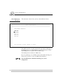
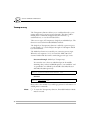
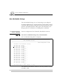
The AXIS 370 Cobra will produce a test printout on the printer which
shows the firmware revision and basic configuration. The default
configuration is for a Generic Printer.
Example:
******** TEST PRINTOUT ********
AXIS 370 Cobra Ver 1.00 960103
Printer Driver #30 Generic Printer
#045 IBM Printer Emulation____ 87: IBM 3287
#005 System Language__________ 0: 037 English (US)
#063 ASCII Char. Set__________ 0: US English
#001 Form Length______________ 72
#002 Line Density_____________ 6
#004 Char. Density____________ 10
12
AXIS 370 Cobra User’s Manual
Section 2: Installation
The Generic Printer configuration will support limited printer
operation. To get more out of your printer, it is advised to configure
the AXIS 370 Cobra for your printer type. Please refer to section 3
before continuing with System Attachment.
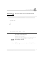
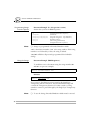
The test printout will show if the AXIS 370 Cobra has been
configured for your printer by the dealer/distributor.
Example:
The printout shows that this AXIS 370 Cobra has already been
configured for an HP LaserJet III printer:
******** TEST PRINTOUT ********
AXIS 370 Cobra Ver 1.00 960103
Printer Driver #49 HP Laserjet III
#045 IBM Printer Emulation____ 87: IBM 3287
#005 System Language__________ 0: 037 English (US)
#063 ASCII Char. Set__________ 13: PC 850
#001 Form Length______________ 66
#002 Line Density_____________ 6
#004 Char. Density____________ 10
AXIS 370 Cobra User’s Manual
13
Section 2: Installation
System Attachment
When your AXIS 370 Cobra is configured, and the configuration is
verified by a test printout, it is time to connect it to the IBM system.
1. Switch off the AXIS 370 Cobra by switching off the printer, or,
if an external power supply is used, by unplugging the power
cord.
2. Set the rotary switch to position ‘0’ (normal print operation).
3. Connect an IBM coax cable leading from the control unit to the
AXIS 370 Cobra.
4. Switch on the AXIS 370 Cobra (switch on the printer or plug in
the external power supply)
The POWER indicator is lit. The SYSTEM indicator flashes for a few
seconds and is then constantly lit.
To verify the attachement, make a local screen copy printout. Use a
terminal attached to the IBM system and send a screen copy print to
the port to which the AXIS 370 Cobra is connected.
You have now completed the installation procedure, and your AXIS
370 Cobra is ready for use. It will not need any attendance or service
during normal operation.
14
AXIS 370 Cobra User’s Manual
Section 3: Configuration
System language
Printer driver
Emulation
Section 3 Configuration
To get the most out of your printer, we recommend that you
configure your AXIS 370 Cobra for your printer type. Only limited
printer operation is supported by the default configuration.
Your AXIS 370 Cobra might already have been configured for you. A
test printout will verify the current configuration, see Section 2.
The configuration can be done in two ways:
•
Configuration from a Terminal
This is the method described in this section. The configuration
method requires a dedicated IBM 3270 terminal such as a 3178,
3179, 3192 or 3472.
Alternatively, a PC equipped with a 3270 terminal emulation
board or an Axis EMMA board (part no 0041-1) can be used.
•
Configuration from the System
The AXIS 370 Cobra can also be configured using down-loaded
programming sequences from the system, see Section 4.
AXIS 370 Cobra User’s Manual
15
System language
Printer driver
Emulation
Section 3: Configuration
Configuration from a Terminal
The AXIS 370 Cobra is equipped with a menu-driven Configuration
Utility. This provides a step-by-step method to adapt the AXIS 370
Cobra to your IBM coax host and printer. Follow these steps to start
the configuration:
1. Switch off the AXIS 370 Cobra. If the power is taken from an
attached printer, then switch the printer off. If you are using an
external power supply, unplug the power cord.
2. Connect a terminal to the AXIS 370 Cobra via a coax cable,
and switch the terminal on. If your terminal is of the DFT type
it is necessary to set it to Control Unit Customization mode so
that it operates as a CUT terminal.
3. Set the rotary switch in position ‘0’ and switch the AXIS 370
Cobra on. The System indicator should now flash rapidly.
Within a few seconds, the Key Definitions Menu should appear on
your terminal.
The rest of Section 3 is a guide to the Configuration Utility. If you
want to restart the configuration, switch the AXIS 370 Cobra off and
on.
16
AXIS 370 Cobra User’s Manual
Section 3: Configuration
System language
Printer driver
Emulation
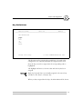
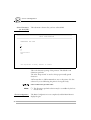
Key Definitions
=========================================================================
AXIS 370 Cobra
Ver 1.00
960103
=========================================================================
KEY DEFINITIONS
_Right
Left
Up
Down
Enter
Assign cursor keys
(c) AXIS COMMUNICATIONS AB 1996
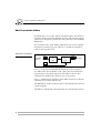
The first menu is for assigning the specific keys to be used in the
configuration. No other keys than the five assigned can be used.
Press the key you wish to assign when the corresponding value is
highlighted.
The highlight will move to the next value after the key has been
assigned.
Right, Left, Up and Down are normally assigned to the cursor keys,
and Enter to the 'Enter' or 'Return' key.
When you have assigned the five keys, the Main Menu will be shown.
AXIS 370 Cobra User’s Manual
17
System language
Printer driver
Emulation
Section 3: Configuration
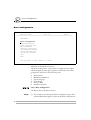
Basic Configuration
=========================================================================
AXIS 370 Cobra
Ver 1.00
960103
=========================================================================
MAIN MENU
Basic Configuration
View Configuration
Print Parameter List
Edit Parameters
Character Translation
User Definable Strings
String Substitutions
Set Factory Defaults
Save
Exit
Use <Up><Down> to move, <Enter> to select
All entries are described in Section 4
The ‘Basic Configuration’ entry initiates a configuration procedure
which will guide you through a sequence of submenus. You will be
prompted for selections in the following order:
1.
2.
3.
4.
5.
6.
Printer Driver
IBM Printer Emulation
System Language
Form Length
Lines per Inch
Characters per Inch
Select ‘Basic Configuration’
The Printer Driver submenu is shown.
Note:
18
❏ If you make an error during the Basic Configuration, press Enter
until the Main Menu appears, and enter the Basic Configuration.
AXIS 370 Cobra User’s Manual
Section 3: Configuration
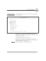
Select Printer Driver
System language
Printer driver
Emulation
This submenu is shown after you have selected ‘Basic Configuration’
in the Main Menu.
=========================================================================
BASIC CONFIGURATION
=========================================================================
PRINTER DRIVER
Generic Printer
IBM Graphics
IBM Proprinter
Epson FX/EX/DFX
Epson LQ
Fujitsu DL (DPL24C)
IBM Matrix (PPDS)
HP LaserJet II
HP LaserJet III
HP LaserJet 4
XEROX 4045
Use <Up><Down> to move, <Enter> to select
A printer driver is a device driver containing all the variables,
including command sequences and character sets, required to drive a
particular range of printers.
The default printer driver is Generic Printer
If your printer is not listed, consult your printer manual. Most
printers can emulate at least one of the common printers like Epson
FX/LQ, IBM Proprinter or HP LaserJet.
Select the Printer Driver matching your printer.
AXIS 370 Cobra User’s Manual
19
System language
Printer driver
Emulation
Section 3: Configuration
Select IBM Printer
Emulation
This submenu is shown after you have selected Printer Driver.
=========================================================================
BASIC CONFIGURATION
=========================================================================
IBM PRINTER EMULATION
IBM
IBM
IBM
IBM
IBM
IBM
3287
3268
4214
3262
4224
4230
Use <Up><Down> to move, <Enter> to select
The AXIS 370 Cobra together with the PC type printer will appear to
the IBM system as an original IBM coax printer. You have to select
which IBM printer emulation that should be used.
The default printer emulation is IBM 3287.
If you are planning to use CECP (Country Extended Code Page) in
LU1 mode, you have to select the IBM 4224 emulation.
Select the IBM Printer Emulation matching your system
configuration.
20
AXIS 370 Cobra User’s Manual
Section 3: Configuration
Select System
Language
System language
Printer driver
Emulation
This submenu is shown after you have selected IBM Printer
Emulation.
============================================================================
BASIC CONFIGURATION
============================================================================
SYSTEM LANGUAGE
_037
037
037
037
260
273
275
277
278
280
281
284
284
285
286
287
English (US)
Netherlands
Portuguese
Canadian Bilingual
Canadian French
Austrian/German
Brazilian
Danish/Norwegian
Swedish/Finnish
Italian
Japanese English
Spanish
Spanish Speaking
English (UK)
Austrian/German alt
Danish/Norwegian alt
288 Swedish/Finnish alt --- XBASIC (Arabic)
289 Spanish alt
--- XCOM2 (Arabic)
290 Japanese Katakana
--- Load Translate Table
297 French
297 French AZERTY
420 Arabic
423 Greek
424 Hebrew
500 International Set 5
500 New Swiss French
500 Belgian
838 Thai
870 East Europe
875 Greek
880 Cyrillic
1026 Turkey (Latin 5)
Use <Up><Down> to move, <Enter> to select
You have to set up the AXIS 370 Cobra for the System Language
matching your IBM system configuration in order to obtain correct
language specific characters.
The default System Language is English (US).
Select the System Language corresponding to your IBM system
configuration.
Note:
❏ If you select ‘Load Translate Table’, your IBM Control Unit will
down-load the System Language when the AXIS 370 Cobra is
switched on.
AXIS 370 Cobra User’s Manual
21
System language
Printer driver
Emulation
Section 3: Configuration
Select Form Length
This submenu is shown after you have selected System Language.
=========================================================================
BASIC CONFIGURATION
=========================================================================
FORM LENGTH
072
Use cursor keys to edit, <Enter> to select
This is the number of lines per page.
The default Form Length is 72 lines for matrix Printer Drivers and 66
lines for laser Printer Drivers.
Selecting 0 lines will inhibit the Form Length setting, i.e. the printer
itself keeps track of the page breaks.
Select the value corresponding to the physical paper size.
Note:
22
❏ The Form Length selection may be overridden by the host in SCS
mode.
AXIS 370 Cobra User’s Manual
Section 3: Configuration
Select Lines per Inch
(LPI)
System language
Printer driver
Emulation
This submenu is shown after you have selected Form Length.
=========================================================================
BASIC CONFIGURATION
=========================================================================
LINES PER INCH
3
4
6
8
Off
Use <Up><Down> to move, <Enter> to select
This is the line spacing of the printout.
The default is 6 Lines per Inch.
‘Off’ means that no LPI commands are sent to the printer. Use this
selection if you set LPI using the printer’s front panel only.
Select a Lines per Inch value.
Note:
❏ The Lines per Inch selection may be overridden by the host in
SCS mode.
AXIS 370 Cobra User’s Manual
23
System language
Printer driver
Emulation
Section 3: Configuration
Select Characters
per Inch (CPI)
This submenu is shown after you have selected LPI.
=========================================================================
BASIC CONFIGURATION
=========================================================================
CHARACTERS PER INCH
5
10
12
15
17
Proportional
Off
Use <Up><Down> to move, <Enter> to select
This is the character spacing of the printout. The default is 10
Characters per Inch.
The value ‘Proportional’ is used to select proportionally spaced
characters.
‘Off’ means that no CPI commands are sent to the printer. Use this
selection if you set CPI using the printer’s front panel only.
Select a Characters per Inch value.
Note:
End of configuration.
24
❏ The Characters per Inch selection may be overridden by the host
in SCS mode.
The Basic Configuration is now completed, and the Main Menu is
displayed again.
AXIS 370 Cobra User’s Manual
Section 3: Configuration
System language
Printer driver
Emulation
Save the Configuration
Select ‘Save’ in the Main Menu.
The following submenu is shown:
=========================================================================
SAVE
=========================================================================
SAVE SETTINGS PERMANENTLY
Yes
No
Use <Up><Down> to move, <Enter> to select
Select ‘Yes’ to save the current configuration permanently.
The system indicator stops flashing while save is in progress. The
Main Menu is displayed after a few seconds.
Note:
❏ The previous configuration remains in the permanent memory
until you select ‘Save’. If you exit without saving, the changes you
have made to the configuration will be lost at the next power-off.
AXIS 370 Cobra User’s Manual
25
System language
Printer driver
Emulation
Section 3: Configuration
Exit the Configuration
Select ‘Exit’ in the Main Menu.
The following submenu is shown:
=========================================================================
SAVE
=========================================================================
EXIT CONFIGURATION
Yes
No
Use <Up><Down> to move, <Enter> to select
Select ‘Yes’ to exit the configuration.
The Configuration Utility is terminated and the screen is left blank.
Disconnect the terminal and connect the AXIS 370 Cobra to your
IBM system.
If you select ‘No’ in this submenu the Main Menu will be displayed
again.
Note:
26
❏ If you exit without saving, the changes you have made to the
configuration will be lost at the next power-off.
AXIS 370 Cobra User’s Manual
Section 4: Advanced Functions
1001010100111
11010001001
010011101
Section 4 Advanced Functions
The AXIS 370 Cobra supports a number of functions beyond
standard IBM printer operation.
During normal mode of operation, AXIS 370 Cobra, together with
your printer, emulates the IBM coax printer selected in your
configuration. In addition, the Extended Emulation Mode gives you
access to functions not available in standard IBM printers.
The examples in this section are intended to give you an overview of
how to use the advanced functions in the Extended Emulation Mode.
Extended Emulation Mode
The advanced functions that you can access in the Extended
Emulation Mode are:
•
Transparency
•
Configuration from the System
•
Character Translation
•
User Definable Strings
•
String Substitutions
•
Bar Code Printing
The functions are programmed, and called, by text sequences inserted
into your documents. The sequences are inserted between enter and
exit commands that control the Extended Emulation Mode (see page
29).
AXIS 370 Cobra User’s Manual
27
1001010100111
11010001001
010011101
Section 4: Advanced Functions
Main Menu
A number of the advanced functions can be programmed or edited
using Configuration from a Terminal. The Main Menu is displayed
when the configuration is started (See “Configuration from a
Terminal” on page 16).
=========================================================================
AXIS 370 Cobra
Ver 1.00
960103
=========================================================================
MAIN MENU
Basic Configuration
View Configuration
Print Parameter List
Edit Parameters
Character Translation
User Definable Strings
String Substitutions
Set Factory Defaults
Save
Exit
Use <Up><Down> to move, <Enter> to select
Basic Configuration
View Configuration
Print Parameter List
Edit Parameters
Character Translation
User Definable Strings
String Substitutions
Set Factory Defaults
Save
Exit
28
−see Section 3.
−display the basic configuration.
−print the parameter list (Appendix A).
−tailor the settings to meet specific needs.
−view and edit tables (see page 32)
−define and edit strings (see page 38)
−search and replace strings (see page 41).
−reset the configuration to defaults.
−store current configuration permanently.
−exit configuration.
AXIS 370 Cobra User’s Manual
Section 4: Advanced Functions
1001010100111
11010001001
010011101
Configuration from the System
This function allows you to configure the AXIS 370 Cobra without
using the Configuration from a Terminal as described in Section 3
By inserting configuration commands in your document, the AXIS
370 Cobra can be tailored to meet special requirements for your print
jobs.
Document example:
&&??%%P
%P
=207,49
=1,66
=4,12
=45,24
=207,10
=207,12
%
&&??000
(Enter extended emulation mode)
(Configuration lead-in sequence)
(Printer Driver = HP LaserJet III)
(Form Length = 66 lines)
(Character Density = 12 CPI)
(IBM printer type = IBM 4224)
(Initialize settings)
(Save settings permanently)
(Configuration trailer sequence)
(Resume normal emulation mode)
The example shows how to select a Printer Driver and program the
Basic Configuration parameters.
The first line is to enter the Extended Emulation Mode.
‘%P’ tells the AXIS 370 Cobra that configuration commands are to
follow. ‘=’ indicates a command line. Each command line has a
function or parameter number.
‘207’ is a function number, followed by a comma and a value. Please
refer to the Technical Reference for a description of functions.
‘1’ is a parameter number, followed by a comma and a value. ‘4’ and
‘45’ are also parameters. The parameters are listed in Appendix A.
‘%’ indicates the end of the configuration commands.
The last line is to exit the Extended Emulation Mode.
Note:
❏ The comments (within brackets) should not be included in your
document.
AXIS 370 Cobra User’s Manual
29
1001010100111
11010001001
010011101
Section 4: Advanced Functions
Transparency
The Transparency function allows you to send data directly to your
printer without any conversion (pass-through). The data could be
ASCII printer commands unsupported by the interface (e.g.
underlined text), or even down-loaded fonts.
There are two types of Transparency, Single-byte and Multi-byte. The
function is accessed in Extended Emulation Mode.
The Single-byte Transparency function is called by a percent sign in
your document (‘%’) and it will pass through one subsequent ASCII
byte (hexadecimal).
The Multi-byte function is started by two successive percent signs.
When the start sequence (‘%%’) is found, the AXIS 370 Cobra
assumes hexadecimal data until a terminating percent sign occurs.
Document Example (Multi-byte Transparency):
You want the text to have an underlined part in the middle.
Assuming that you have an IBM Proprinter, ‘start underline’ and
‘stop underline’ are defined by the ASCII codes $1B,$2D,$31
and $1B,$2D,$30 respectively:
This is %%1B2D31%underlined%%1B2D30% text
Printout:
This is underlined text
Please refer to the manual for your PC type printer for information on
ASCII printer commands.
Note:
30
❏ To access the Transparency function, Extended Emulation Mode
must be entered.
AXIS 370 Cobra User’s Manual
Section 4: Advanced Functions
1001010100111
11010001001
010011101
Redefine Configuration and Transparency Sequences
The Start and Stop Transparency and Configuration are controlled by
three string parameters:
•
•
•
Transparency Lead-In Sequence (#070), default ‘%%’.
Configuration Lead-In Sequence (#071), default ‘%P’.
Transparency/Configuration Trailer Sequence (#072), default ‘%’.
See Appendix A for a description of the parameters. The parameters
can be redefined using Configuration from the System.
Document Example:
Change the Transparency Lead-In Sequence from ‘%%’ to ‘!?<’
(DBC codes $19,$18,$09). Also, change the Trailer Sequence
from ‘%’ to ‘>&’ (DBC codes $08,$30):
%P
=70,$19,$18,$09
=72,$08,$30
=207,10
=207,12
>&
Notes:
(Configuration lead-in sequence)
(Change the transparency lead-in sequence to ‘!?<’)
(Change the configuration trailer sequence to ‘>&’)
(Initialize settings)
(Save settings permanently)
(Configuration trailer sequence (new))
❏ To redefine the sequences, Extended Emulation Mode must be
entered. The sequences are reset to their default values if you exit
and re-enter Extended Emulation Mode.
❏ The sequences are redefined immediately. Therefore, the new
sequence ‘>&’ must be used as Configuration Trailer Sequence in
the document.
Document Example:
Use the new sequences in the same example as in the previous
section (Multi-byte Transparency):
This is !?<1B2D31>&underlined!?<1B2D30>& text
This results in the same printout as in the previous section.
AXIS 370 Cobra User’s Manual
31
1001010100111
11010001001
010011101
Section 4: Advanced Functions
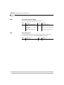
Edit Translation Tables
Normally, there is no need to edit the translation tables. The character
translation tables activated by the Printer Driver and System Language
selections are designed to produce the same printouts as the emulated
IBM printer.
If you should need to make further adjustments, this section explains
the character translation process and how to modify the translation
tables to meet specific needs.
Character Translation
from IBM
system
LU1
EBCDIC
to
DBC
DBC
to
ASCII
ASCII
to printer
LU3
LU1 (i.e. SCS) data stream EBCDIC characters are first translated
into DBC codes (Device Buffer Code). This is the internal character
representation in the AXIS 370 Cobra. The DBC codes are then
translated into ASCII codes, which are sent to the printer.
LU3 (i.e. DSE/DSC/non-SCS) data stream DBC characters are directly
translated into printable ASCII codes.
The EBCDIC-to-DBC translation table is determined by the selected
System Language.
The DBC-to-ASCII table is determined by the selected Printer Driver.
32
AXIS 370 Cobra User’s Manual
Section 4: Advanced Functions
Editing Translation
Tables using a
Terminal
1001010100111
11010001001
010011101
Start the Configuration from a Terminal as described in Section 3.
Select the Character Translation entry in the Main Menu.
The Character Translation menu is displayed:
=========================================================================
CHARACTER TRANSLATION
=========================================================================
CHARACTER TRANSLATION FUNCTIONS
View/Edit DBC to ASCII table
View/Edit EBCDIC to DBC table
Print DBC to ASCII table
Print DBC to ASCII table (hex)
Print EBCDIC to ASCII table
Print EBCDIC to ASCII table (hex)
Print EBCDIC to DBC table (hex)
Return to Main Menu
Use <Up><Down> to move, <Enter> to select
Select ‘View/Edit DBC to ASCII table’.
The translation table is displayed (see next page):
AXIS 370 Cobra User’s Manual
33
1001010100111
11010001001
010011101
Section 4: Advanced Functions
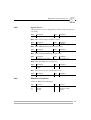
=========================================================================
VIEW/EDIT DBC TO ASCII TABLE
=========================================================================
ASCII Char. Set: PC-850
0
1
2
3
4
5
6
7
8
9
A
B
C
D
E
F
_0 $20 $20 $30 $26 $85 $84 $B7 $8E $61 $71 $41 $51 $20 $D0 $20 $D1
1 $20 $3D $31 $2D $8A $89 $D4 $D3 $62 $72 $42 $52 $20 $E7 $20 $E8
2 $20 $27 $32 $2E $8D $8B $DE $D8 $63 $73 $43 $53 $20 $EC $20 $ED
3 $20 $22 $33 $2C $95 $94 $E3 $99 $64 $74 $44 $54 $20 $20 $20 $20
4 $20 $2F $34 $3A $97 $81 $EB $9A $65 $75 $45 $55 $20 $20 $20 $20
5 $20 $5C $35 $2B $C6 $83 $C7 $B6 $66 $76 $46 $56 $FB $F1 $20 $20
6 $20 $7C $36 $AA $E4 $88 $E5 $D2 $67 $77 $47 $57 $FD $F6 $20 $20
7 $20 $DD $37 $EE $98 $8C $59 $D7 $68 $78 $48 $58 $FC $9E $20 $20
8 $3E $3F $38 $F8 $85 $93 $41 $E2 $69 $79 $49 $59 $AB $FA $20 $20
9 $3C $21 $39 *** $8A $96 $45 $EA $6A $7A $4A $5A $AC $AE $20 $20
A $5B $24 $E1 $5E $82 $A0 $45 $B5 $6B $91 $4B $92 $F3 $AF $20 $20
B $5D $BD $F5 $7E $8D $82 $49 $90 $6C $9B $4C $9D $A7 $A8 $20 $20
C $29 $9C $23 $F9 $95 $A1 $4F $D6 $6D $86 $4D $8F $A6 $AD $20 $20
D $28 $BE $40 $60 $97 $A2 $55 $E0 $6E $87 $4E $80 $F4 $E6 $20 $20
E $7D $23 $25 $EF $81 $A3 $59 $E9 $6F *** $4F $3B $B8 $20 $20 $20
F $7B $CF $5F $F7 $87 $A4 $43 $A5 $70 *** $50 $2A $A9 $20 $20 $20
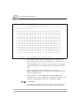
Use <Right> to enter View/Edit mode, <Enter> to exit
The translation table shows the ASCII codes for each DBC code.
Appendix B shows a printout of the characters for each DBC code.
Read each DBC code as a column and row position where you find
the ASCII translation. For example, DBC $2A translates to ASCII
$E1.
This is the table for the PC-850 character set used by the
HP LaserJet III printer driver. Changing the printer driver selection
will also change the table.
Three asterisks (***) in the table indicate that the DBC code is
translated into a string of ASCII codes, rather than a single code. The
string is not displayed in the table but is available for editing.
To View/Edit:
Press Right. The highlight moves to the ASCII value for DBC $00.
Use the cursor keys to move and press Enter to enter edit mode.
34
AXIS 370 Cobra User’s Manual
Section 4: Advanced Functions
1001010100111
11010001001
010011101
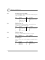
Example 1:
To change a left bracket ‘[’ at position 0A to a left bracket ‘{’
which has ASCII value $7B.
1. Move the highlight to position 0A in the table.
2. Press Enter to edit.
The row above the help message contains the edit field. This field
shows the current DBC position and the corresponding ASCII
value. The bottom of the screen looks like this:
E
F
$7D $23 $25 $EF $81 $A3 $59 $E9 $6F *** $4F $3B $B8 $20 $20 $20
$7B $CF $5F $F7 $87 $A4 $43 $A5 $70 *** $50 $2A $A9 $20 $20 $20
$0A:$5B
Use <Right> to enter View/Edit mode, <Enter> to exit
Now replace the value $5B with the new value $7B:
3. Change $5B to $7B using the Up/Down keys.
4. Press Enter to resume view mode.
The position 0A in the table is now highlighted, and has the new
value $7B.
5. Press Left to move the cursor to the home position (under
the upper left digit ‘0’).
6. Press Enter to exit and return to the Character Translation
Menu.
From now on, a left bracket ‘[’ is replaced by ‘{’ in printouts.
AXIS 370 Cobra User’s Manual
35
1001010100111
11010001001
010011101
Section 4: Advanced Functions
Example 2:
Change the overscored semicolon ‘;’ at position 9E to a ‘bullet’
character ‘•’ which has ASCII value $FA:
1. Move the highlight to position 9E in the table. The three
asterisks indicate that this DBC character translates to a string
rather than a single character.
2. Press Enter. The bottom of your screen now looks like this:
E
F
$7D $23 $25 $EF $81 $A3 $59 $E9 $6F *** $4F $3B $B8 $20 $20 $20
$7B $CF $5F $F7 $87 $A4 $43 $A5 $70 *** $50 $2A $A9 $20 $20 $20
$9F:$EE,$08,$3B
Use <Right> to enter View/Edit mode, <Enter> to exit
Replace the string $EE,$08,$3B (overscore, backspace,
semicolon) with the value $FA (the bullet character):
3. Change $EE to $FA.
4. Step Right, and change $08,$3B to $00,$00.
5. Place the cursor under the first $00 to delete this and all
subsequent zero values.
6. Press Enter to resume view mode.
The position 9E in the table is now highlighted, and the three
asterisks are replaced with $FA.
7. Exit edit mode.
Note:
36
❏ Changing printer driver will override all changes to the table.
AXIS 370 Cobra User’s Manual
Section 4: Advanced Functions
Editing Translation
Tables using
the System
The translation table can be modified from the system.
Document Example (see also previous examples):
Change the overscored semicolon ‘;’ at position 9E to a ‘bullet’
character ‘•’ by inserting the following programming sequences in
your document:
%P
=205,$9E,$FA
=207,10
=207,12
%
Note:
1001010100111
11010001001
010011101
(Configuration lead-in sequence)
(Translate DBC $9E to ASCII $FA)
(Initialize settings)
(Save settings permanently)
(Configuration trailer sequence)
❏ To edit, Extended Emulation Mode must be entered.
‘205’ is the function number, ‘$9E’ is the DBC table position and
‘$FA’ is the new ASCII value (old ASCII value/ values are deleted).
You can modify any number of DBC positions by adding lines with
function 205 calls.
The EBCDIC to DBC table is editable in a similar fashion, the only
difference being that an EBCDIC character translates to a single DBC
character only. The function number for EBCDIC table editing is
204.
AXIS 370 Cobra User’s Manual
37
1001010100111
11010001001
010011101
Section 4: Advanced Functions
User Definable Strings
The User Definable Strings is a set of 255 strings at your disposal.
A common application is to program and store various printer control
commands, and send them to the printer using string references rather
than the commands themselves. Please refer to the manual for your
PC type printer for information on ASCII printer commands.
Programming Strings
from a Terminal
Start the Configuration from Terminal as described in Section 3.
Select the User Definable Strings entry in the Main Menu.
The User Definable Strings Menu is displayed:
=========================================================================
USER DEFINABLE STRINGS
=========================================================================
Free String Area: $1C41
View/Edit User Definable Strings
$01
$02
$03
$04
$05
$06
$07
$08
$09
$0A
$0B
$0C
$0D
$0E
$0F
$10
User
User
User
User
User
User
User
User
User
User
User
User
User
User
User
User
Def.
Def.
Def.
Def.
Def.
Def.
Def.
Def.
Def.
Def.
Def.
Def.
Def.
Def.
Def.
Def.
String____
String____
String____
String____
String____
String____
String____
String____
String____
String____
String____
String____
String____
String____
String____
String____
.
.
.
.
.
.
.
.
.
.
.
.
.
.
.
.
Use cursor keys to edit, <Enter> to exit
The numbers in the leftmost column are the string numbers, ranging
from $01 to $FF.
38
AXIS 370 Cobra User’s Manual
Section 4: Advanced Functions
1001010100111
11010001001
010011101
Example (IBM Proprinter):
You want to store commands for underlining text. If you have an
IBM Proprinter, ‘start underline’ and ‘stop underline’ are defined
by the ASCII codes $1B,$2D,$31 and $1B,$2D,$30 respectively.
1. When string number $01 is highlighted, press Right to
enter edit mode. The string is set to $00.
2. Edit the string to $1B,$2D,$31 using the cursor keys (press
Right to expand the string).
3. Press Enter.
4. Edit string number $02 to $1B,$2D,$30
Your screen now looks like this:
=========================================================================
USER DEFINABLE STRINGS
=========================================================================
Free String Area: $1C3B
View/Edit User Definable Strings
$01
$02
$03
$04
$05
$06
$07
$08
$09
$0A
$0B
$0C
$0D
$0E
$0F
$10
User
User
User
User
User
User
User
User
User
User
User
User
User
User
User
User
Def.
Def.
Def.
Def.
Def.
Def.
Def.
Def.
Def.
Def.
Def.
Def.
Def.
Def.
Def.
Def.
String____
String____
String____
String____
String____
String____
String____
String____
String____
String____
String____
String____
String____
String____
String____
String____
$1B,$2D,$31.
$1B,$2D,$30.
.
.
.
.
.
.
.
.
.
.
.
.
.
.
Use cursor keys to edit, <Enter> to exit
Press Enter until the Main Menu is displayed.
The maximum String length is determined by the Free String Area.
Note:
❏ Changing printer driver will override all User Definable Strings.
AXIS 370 Cobra User’s Manual
39
1001010100111
11010001001
010011101
Section 4: Advanced Functions
Programming Strings
from the System
Document Example (See also previous section):
Assume that you have an IBM Proprinter:
%P
=209,$00
=209,$01,$1B,$2D,$31
=209,$02,$1B,$2D,$30
=207,10
=207,12
%
Note:
(Configuration lead-in sequence)
(Delete all)
(Program string 01 to ‘start underline’)
(Program string 02 to ‘stop underline’)
(Initialize settings)
(Save settings permanently)
(Configuration trailer sequence)
❏ Strings are programmed in Extended Emulation Mode.
‘209’ is the function number, ‘$01’ is the string number. If the string
number is not followed by a value, the string is deleted.
‘209,$00’ will delete all previously programmed User Definable
Strings.
Using the Strings
Document Example (IBM Proprinter):
To underline text in a document using the strings number $01
and $02 (see previous example):
This is %01underlined%02 text
Printout:
This is underlined text
As you can see, the function syntax is equal to the Single-byte
Transparency function. However, the User Definable Strings will
override the Transparency function. If a value is used as a string
number it cannot be passed through by the Single-byte Transparency
function.
Note:
40
❏ To use the Strings, Extended Emulation Mode must be entered.
AXIS 370 Cobra User’s Manual
Section 4: Advanced Functions
1001010100111
11010001001
010011101
String Substitutions
This function is useful when you want to print a document that is
prepared for a different PC type printer than yours.
The document contains control commands for a specific printer, and
you have to convert these commands in order to print this document
with your printer. Instead of changing the document, you can let the
AXIS 370 Cobra do the conversion for you by using String
Substitution.
The String Substitution function will search the data stream for a
specified sequence of ASCII characters and substitute them with
another sequence. Note that this function operates after the character
and control code conversion.
Example:
Assume that you have an HP LaserJet. The document is prepared
for an IBM Proprinter and contains ‘start underline’ and ‘stop
underline’ pass-through commands at several locations. To print
the document with an HP LaserJet, the sequences must be
converted.
To ‘start underline’, the IBM Proprinter uses ASCII value string
$1B, $2D, $31 and the HP LaserJet uses $1B, $26, $64, $44.
‘Stop underline’ commands are $1B, $2D, $30 and $1B, $26,
$64, $40 respectively.
The following pages show how to program these substitutions, both
from a Terminal and the System.
AXIS 370 Cobra User’s Manual
41
1001010100111
11010001001
010011101
Section 4: Advanced Functions
Programming String
Substitutions from a
Terminal
Start the Configuration from Terminal as described in Section 3.
1. Select the String Substitutions entry in the Main Menu. The
String Substitutions Menu consists of pairs of Match and
Substitute strings.
2. Edit the first two string pairs. See “User Definable Strings” on
page 38 on how to edit strings.
The String Substitutions Menu now looks like this:
=========================================================================
STRING SUBSTITUTIONS
=========================================================================
Free String Area: $1C33
View/Edit ASCII String Substitutions
$01
$02
$03
$04
$05
$06
$07
$08
$09
$0A
$0B
$0C
$0D
$0E
$0F
$10
Match String
Subst. String
Match String
Subst. String
Match String
Subst. String
Match String
Subst. String
Match String
Subst. String
Match String
Subst. String
Match String
Subst. String
Match String
Subst. String
1_____
1_____
2_____
2_____
3_____
3_____
4_____
4_____
5_____
5_____
6_____
6_____
7_____
7_____
8_____
8_____
$1B,$2D,$31.
$1B,$26,$64,$44.
$1B,$2D,$30.
$1B,$26,$64,$40.
.
.
.
.
.
.
.
.
.
.
.
.
Use cursor keys to edit, <Enter> to exit
When a Match String is encountered in the ASCII data stream, it will
be replaced by the subsequent Substitute String.
The maximum Match String length is 50 bytes. The maximum
Substitute String length is determined by the Free String Area.
Notes:
❏ Extensive use of Substitutions may slow down the printing speed.
❏ Changing Printer Driver will delete all String Substitutions.
42
AXIS 370 Cobra User’s Manual
Section 4: Advanced Functions
The same programming example as above can also be obtained by
inserting the following lines into your document:
Programming String
Substitutions from the
System
%P
=210,$00
=210,$01,$1B,$2D,$31
=210,$02,$1B,$26,$64,$44
=210,$03,$1B,$2D,$30
=210,$04,$1B,$26,$64,$40
=207,10
=207,12
%
Note:
1001010100111
11010001001
010011101
(Configuration lead-in sequence)
(Delete all)
(Start underline - Proprinter)
(Start underline - HP LaserJet)
(Stop underline - Proprinter)
(Stop underline -HP LaserJet)
(Initialize settings)
(Save settings permanently)
(Configuration trailer sequence)
❏ String Substitutions are programmed in Extended Emulation
Mode.
‘210’ is the function number. If the string number is not followed by
data, the string will be deleted.
‘210,$00’ will delete all String Substitutions.
AXIS 370 Cobra User’s Manual
43
1001010100111
11010001001
010011101
Section 4: Advanced Functions
Bar Codes
This function gives you easy access to a range of standard bar code
types. You can design every single bar code printout to meet your
specific requirements, such as width and height.
There are two functions and two parameters that are used for printing
bar codes:
•
•
•
•
Function ‘211’ defines the bar code.
Function ‘212’ prints the bar code.
Bar Code Driver (#093).
Bar Code Attributes (#094).
The definition has to be done before a bar code can be printed.
See Appendix A for a description of parameters.
Define Bar Codes
The function ‘211’, which is to be inserted into a document, has the
following syntax:
211,value 1,value 2,value 3,value 4,value 5
The function number is followed by five bar code specification values.
All five values must be specified:
value 1: Bar
1
3
8
9
12
13
17
Code Type. Selectable values (in decimal):
= Code 39
= UPC-A
= EAN8
= EAN13
= 2 of 5 Interleaved
= Codabar Matrix
= Code 128
value 2: Module
Width as a multiple of 1/120 inch.
The value may range from 1 to 32 (in decimal).
value 3: Bar
Code Height in number of lines (1/6 inch).
The value may range from 1 to 32 (in decimal).
44
AXIS 370 Cobra User’s Manual
Section 4: Advanced Functions
1001010100111
11010001001
010011101
value 4: Human
Readable Text. Selectable values:
0 = No textline below the bar code
1 = Human readable textline below the bar code.
2 = Human readable textline below the bar code with
empty line in between.
value 5: Horizontal
Bar Code Start Position in 1/12 inch steps.
The value may range from 1 to 255 (in decimal).
Note:
Print Bar Code
❏ When you set the horizontal width and start position, make sure
that the printout will fit on the paper area.
The function ‘212’ prints a bar code according to the settings in the
bar code definition. The syntax is as follows:
212,“bar code data”
Document Example:
%P
=211,9,2,2,1,10
=212,“123456789012”
%
(Configuration lead-in sequence)
(Define Bar Code)
(Print Bar Code)
(Configuration trailer sequence)
Printout
Note:
❏ To Define and Print bar code, Extended Emulation Mode must
be entered.
AXIS 370 Cobra User’s Manual
45
1001010100111
11010001001
010011101
Section 4: Advanced Functions
Automatic Page Orientation
Note:
❏ This section applies to Laser Printer drivers only.
The automatic page orientation function calculates page sizes based on
the following page formatting parameters:
•
•
•
•
•
Form Length (#001)
Line Density (#002)
Maximum Print Position (#003)
Character Density (#004)
Automatic Orientation/Physical Paper Size (#074)
Portrait or landscape orientation is automatically selected depending
on the calculated length/width ratio. If the calculated page size is
larger than the physical page in either orientation, and Orientation
(#148) is set to Computer Output Reduction (COR), COR mode is
used.
The COR function is designed to accommodate traditional data
processing applications that require 66 lines of 132 columns on laser
printers. The following changes are made:
46
•
The page is printed in landscape orientation.
•
The line spacing is set to 70% of that specified.
•
The character density is changed as follows:
10 CPI ⇒ 13.3 CPI
12 CPI ⇒ 15 CPI
15 CPI ⇒ 20 CPI
17 CPI ⇒ 27 CPI
•
The top and left margins are set to 0.5".
AXIS 370 Cobra User’s Manual
Section 5: Solving Problems
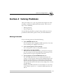
Section 5 Solving Problems
This section helps you to solve any problems that might arise when
installing or using your AXIS 370 Cobra interface. There are two
major areas of difficulty:
•
Missing printouts
•
Incorrect printouts
Use the following checklists to pinpoint the possible cause. If your
problems should continue, please contact your dealer/distributor.
Missing Printouts
In case of missing printout, check the following:
1. Is the POWER indicator on?
No: Your printer cannot supply the AXIS 370 Cobra. You must
use an external power supply (see Section 2).
2. Is the attached printer on-line (Ready)?
No: Set the printer on-line (see the printer manual).
3. Is the printer correctly attached?
Make sure that the AXIS 370 Cobra is connected to the proper
port. If your printer has both parallel and serial input ports, the
printer must be set up for the parallel connection.
4. System printouts: Is the SYSTEM indicator on?
No: The AXIS 370 Cobra is not correctly connected to the
system, or the power-up routine has been disturbed. Restart the
interface (power-off/power-on). If this doesn’t help, make sure
that the coax cable is properly connected between the interface
and system. If the cable works with another 3270 printer, contact
your distributor.
Flashing: The AXIS 370 Cobra is in Test Mode. To exit set the
rotary switch to position ‘9’, or switch the AXIS 370 Cobra off
and on.
AXIS 370 Cobra User’s Manual
47
Section 5: Solving Problems
Incorrect Host Printouts
There are five major types of incorrect printouts:
Some Characters are
Printed Incorrectly
•
Characters like ä ü Ä Ü are printed as { } [ ]
Most likely an incorrect System Language has been selected.
Select the System Language matching your system configuration,
or ‘Load Translate table’ to make your Control Unit down-load
the System Language for you. See “Select System Language” on
page 21.
•
Characters like é ì ô ü are printed as e i o u
Your printer has not been set up for the character set matching
the ASCII Character Set selection in the Printer Driver. Make
sure that you have selected the correct Printer Driver.
If this doesn’t help, your printer may not be able to print all the
characters that the system produces. Print out the DBC-to-ASCII
translation table (See “Edit Translation Tables” on page 32), and
compare this to the table in Appendix B. In some cases it is possible to
edit the translation table, or to select another character set in your
printer. Consult your distributor for further details.
Corrupted Printouts
This is generally caused by selecting a Printer Driver not matching
your printer. The control commands will then be misinterpreted by
the printer, causing corrupted printouts. If changing Printer Driver
does not help, you can use the ASCII hexdump function (See
“Producing Hexdumps” on page 51) to locate the control commands
causing the problem.
Incorrect Page Breaks
Most likely an incorrect Form Length setting. Recommended values
are listed in Appendix A. Make sure that you have selected the correct
Printer Driver.
48
AXIS 370 Cobra User’s Manual
Section 5: Solving Problems
Lost characters at end
of line
Some laser printers cannot print a full line of 80 characters in 10 CPI.
Change the Characters per Inch setting to 12 CPI.
Advanced users: You might also modify the 10 CPI string contents to
set 10.2 CPI instead.
Additional empty lines
or spaces
Your system application may assume the utilization of an IBM RPQ.
Several empty lines can be caused by an incorrect logical buffer size. If
you are not familiar with IBM RPQ’s and buffer sizes, your distributor
should be able to help you.
AXIS 370 Cobra User’s Manual
49
Section 5: Solving Problems
Reporting Problems
If you run into problems that you can’t solve on your own, it is
important that you make an error report for your System Manager or
distributor. The error report should include:
•
A printout with a description of the errors
•
If possible, a correct printout
•
A Parameter List
•
A System and ASCII hexdump
If you need technical support, please contact your dealer. If they can’t
help you, they will forward your request through the appropriate
channels.
If you are connected to Internet, have a look at the Axis WWW Home Page
at http://www.axis.se/. Here you can find information about the company
and our products. You can also down-load on-line manuals, tools such as the
Acrobat Reader for different platforms, and the latest versions of the software
utilities. You can also get files and information through anonymous ftp: log
in to ftp.axis.se and go to the /pub/axis directory, or enter
ftp://ftp.axis.se/pub/axis in your WWW browser.
Printing the
Parameter List
The Parameter List shows the complete configuration. A selection of
parameters are described in Appendix A. To print the Parameter List,
do as follows:
1. Make sure that your printer is on-line.
2. Set the rotary switch to ‘9’, and wait for approx. 3 seconds
until the SYSTEM indicator starts to flash. You are now in the
Test Mode.
3. Set the rotary switch to ‘8’ to start the printout.
4. Set the rotary switch to ‘9’ when the printout is completed.
The SYSTEM indicator will stop flashing.
5. Select position ‘0’ to resume normal print operation.
50
AXIS 370 Cobra User’s Manual
Section 5: Solving Problems
Producing Hexdumps
A hexdump is a printout where the input data stream is printed as
hexadecimal byte values rather than being interpreted as characters
and control codes. The AXIS 370 Cobra features two different types
of hexdump modes:
•
System hexdump
This mode will trap the input data before the character and
control code conversion. The data is printed as EBCDIC or DBC
hexadecimal values.
•
ASCII hexdump
The input data is converted to ASCII hexadecimal values before
printing. This mode is useful if you want to see what printer
control command a certain IBM control code corresponds to.
To produce a hexdump, do as follows:
1. Switch the printer and AXIS 370 Cobra off and on.
2. Set the rotary switch to ‘9’, and wait for approx. 3 seconds
until the SYSTEM indicator starts to flash. You are now in the
Test Mode.
3. Select position ‘4’ for system hexdump, or position ‘3’ for
ASCII hexdump.
4. Repeat your print job. The data will now be printed in
hexadecimal form.
5. Set the rotary switch to ‘9’ when the printout is completed.
The SYSTEM indicator will stop flashing.
6. Select position ‘0’ to resume normal print operation.
Example of ASCII hexdump:
AXIS 370 Cobra
Ver 1.00 960103
Printer Driver #49 HP LaserJet III
0001 1B 26 61 33 36 30 48 1B 26 61 35 32 38 56 1B 26 “-&a360H-&a528V-&”
0002 61 33 36 30 48 1B 26 61 35 32 38 56 54 45 53 54 “a360H-&a528VTEST”
AXIS 370 Cobra User’s Manual
51
Section 5: Solving Problems
Error messages
There are five different error conditions that will cause the AXIS 370
Cobra to print an error message on your printer:
E2-PERMANENT MEMORY CHECKSUM ERROR, FACTORY DEFAULTS SET
This message indicates that the non-volatile memory has been
corrupted. The interface is automatically set to factory default state
(your configuration is lost). If the message does not re-appear after
power-off/power-on, configure the AXIS 370 Cobra (Section 3).
E6-MEMORY OVERFLOW: FREE STRING AREA EXHAUSTED
The available string area is exhausted. You must remove some strings
from your configuration. (User Definable Strings, String Substitutions
or String parameters in the Parameter List). The size of the available
string area is printed in the Parameter List header, and is also displayed
in all string programming menus.
BE-BAR CODE ERROR
Incorrect or insufficient bar code definition. The bar code must be
specified with five values. See “Bar Codes” on page 44.
BD-SOFTWARE/HARDWARE ERROR
The software cannot run in the current hardware. Contact your
dealer.
BF-GDDM SUPPORT NOT ENABLED: NOT ENOUGH ROOM IN FREE
STRING AREA; 3352($0D18) BYTES REQUIRED
An attempt has been made to enable GDDM (#142) with insufficient
free memory. You must remove some strings from your configuration.
(User Definable Strings, String Substitutions or String parameters in
the Parameter List). The size of the available string area is printed in
the Parameter List header, and is also displayed in all string
programming menus.
52
AXIS 370 Cobra User’s Manual
Appendix A: The Parameter List
Appendix A
The Parameter List
The Parameter List shows the complete configuration of the AXIS 370
Cobra. Each parameter contains a value or string that is used to
determine how the AXIS 370 Cobra should behave towards the host
and towards the printer.
In this appendix you will find a selection of parameters, i.e. the Basic
Configuration, Please refer to the AX-7 Cobra+Technical Reference
Manual for parameters not covered by this manual.
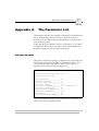
Printout Example
This printout shows the beginning of a Parameter List (the header and
the first 10 parameters) for the HP LaserJet III printer driver. Your
own printout may differ depending on printer driver selection,
firmware revision and customized configuration.
AXIS 370 Cobra
Ver 1.00
960103
Printer Driver #49 HP LaserJet III
Free String Area: $1A0F
#001
#002
#003
#004
#005
#006
#007
#008
#009
#010
Form Length______________
Line Density_____________
Max. Print Pos.__________
Char. Density____________
System Language__________
True Screen Image________
FF before Hardcopy_______
FF after Hardcopy________
Monocase_________________
Suppress Ctrl. Codes_____
66
6
132
10
0: 037 English (US)
No
No
Yes
No
No
If any User Definable Strings or String Substitutions are defined, they
will be printed after the Parameter List.
AXIS 370 Cobra User’s Manual
53
Appendix A: The Parameter List
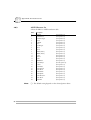
Printer Drivers
A printer driver is a device driver containing all the parameters
required to drive a particular range of printers. The following printer
drivers are available:
No
Title
No
Title
30
Generic Printer
44
IBM Matrix (PPDS)
31
IBM Graphics
48
HP LaserJet II
32
IBM Proprinter
49
HP LaserJet III
33
Epson FX/EX/DFX
52
Xerox 3700/4045
34
Epson LQ
55
HP LaserJet 4
35
Fujitsu DL (DPL24C)
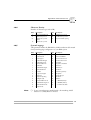
Parameter Descriptions
#001
Form Length
Number of lines per page. The AXIS 370 Cobra causes the paper to be
ejected (cut sheet) or advanced to the next top of form (fanfold) when
the specified number of lines have been printed.
Value
#002
Description
Value
1-255
Number of lines per page
0
Do not count lines
* 66
66
48
8.5" fanfold
* 72
64
Letter size cut sheet
Description
A4 size cut sheet
11" fanfold (default, laser printers)
12" fanfold (default, matrix printers)
-
-
Line Density
Number of lines per inch (LPI).
Value
54
Description
Value
Description
0
Do not set Line Density
*6
6 Lines per Inch (default)
3
3 Lines per Inch
8
8 Lines per Inch
4
4 Lines per Inch
-
-
AXIS 370 Cobra User’s Manual
Appendix A: The Parameter List
#004
Character Density
Number of characters per inch (CPI).
Value
#005
Description
Value
Description
0
Do not set Char. Density
15
15 Characters per Inch
5
5 Characters per Inch
17
16.7 Characters per Inch
* 10
10 Characters per Inch
(default)
99
Proportional Char. spacing
12
12 Characters per Inch
-
-
System Language
This parameter makes the EBCDIC-to-DBC translation table match
the System Language configuration of your IBM system.
Note:
Value
Description
*0
037 English (US) (default)
Value
18
Description
297 French
1
037 Netherlands
19
297 French AZERTY
2
037 Portuguese
20
500 International Set 5
3
037 Canadian Bilingual
21
500 New Swiss French
4
260 Canadian French
22
500 Belgian
5
273 Austrian/German
23
290 Japanese Katakana*
6
275 Brazilian
30
420 Arabic*
7
277 Danish/Norwegian
31
424 Hebrew*
8
278 Swedish/Finnish
32
423 Greek*
9
280 Italian
33
1026 Turkey (Latin 5)*
10
281 Japanese English
35
880 Cyrillic*
11
284 Spanish
36
870 East Europe*
12
284 Spanish Speaking
37
875 Greek*
13
285 English (UK)
38
838 Thai*
14
286 Austrian/German alt
80
- - - XBASIC (Arabic)*
15
287 Danish/Norwegian alt
81
- - - XCOM2 (Arabic)*
16
288 Swedish/Finnish alt
99
- - - Load Translate Table
17
289 Spanish alt
❏ To use system languages marked with *, the matching ASCII
Character set (#063) must be selected.
AXIS 370 Cobra User’s Manual
55
Appendix A: The Parameter List
#040
Extended Emulation Mode
Selects the default Extended Emulation Mode.
#041
Value
Description
*0
No Extended Emulation Mode
(default)
Value
3
Description
MPI compatible mode
1
Escape Character translates to
ASCII $1B
4
Memorex 2068 compatible mode
2
Standard Extended Emulation
Mode
5
Maersk Data compatible mode
Escape Character
Select the DBC character code used for Single-byte Transparency,
User Definable Strings and Extended Emulation Mode 1.
56
Value
Description
Value
Description
$10-$BF
(valid range)
*$2E
‘%’ (default)
AXIS 370 Cobra User’s Manual
Appendix A: The Parameter List
#042
Option Select 1
This parameter controls 8 independent switches. Each bit represents
one switch.
Value
Description
Value
Description
$00-$FF
(valid range)
*$02
(default)
Bit 1 ($02): LU1 Form Feed valid in 1st line.
Value
Description
Value
Description
0
No
*1
Yes (default)
Bit 3 ($08): SHF Maximum Print Position select.
Value
Description
Value
Description
*0
Default MPP is used (default)
1
Current MPP is used
Bit 5 ($20): SVF Maximum Page Length select.
Value
Description
Value
Description
0
Default MPL is used (default)
*1
Current MPL is used
Bit 6 ($40): Extended SCS Transparency.
Value
Description
Value
Description
*0
SCS TRN data as SCS codes
(default)
1
SCS TRN data as ASCII codes
Bit 7 ($80): Action at coax communication loss.
#045
Value
Description
Value
Description
*0
No action (default)
1
Restart attempt after 60 seconds
IBM Printer Emulation
Selects the IBM Printer Emulation.
Value
Description
Value
Description
*87
IBM 3287 (default)
62
IBM 3262
68
IBM 3268
24
IBM 4224 (non-IPDS)
14
IBM 4214
30
IBM 4230
AXIS 370 Cobra User’s Manual
57
Appendix A: The Parameter List
#063
ASCII Character Set
Selects the DBC to ASCII translation table.
Note:
58
Value
Description
0
US English
(7-bit symbol set)
1
Swedish/Finnish
(7-bit symbol set)
2
Danish/Norwegian
(7-bit symbol set)
3
German
(7-bit symbol set)
4
UK English
(7-bit symbol set)
5
Italian
(7-bit symbol set)
6
French/Belgian
(7-bit symbol set)
7
Spanish
(7-bit symbol set)
8
Japanese
(7-bit symbol set)
9
XBASIC (Arabic)
(8-bit symbol set)
10
XCOM2 (Arabic)
(8-bit symbol set)
11
PC Set 2
(8-bit symbol set)
12
Roman-8
(8-bit symbol set)
13
PC-850
(8-bit symbol set)
14
ISO/ECMA94
(8-bit symbol set)
15
PC-942 Shift JIS
(8/16-bit symbol set)
16
JIS X0201
(8-bit symbol set)
20
PC-864 Arabic
(8-bit symbol set)
21
PC-862 Hebrew
(8-bit symbol set)
22
PC-869 Greek
(8-bit symbol set)
23
PC-857 Turkish
(8-bit symbol set)
25
PC-855 Cyrillic
(8-bit symbol set)
26
PC-852 PC Latin 2
(8-bit symbol set)
27
PC-851 Greek
(8-bit symbol set)
28
PC-874 Thai
(8-bit symbol set)
❏ The default setting depends on the selected printer driver.
AXIS 370 Cobra User’s Manual
Appendix A: The Parameter List
#066
Option Select 2
This parameter controls 8 independent switches. Each bit represents
one switch.
Value
Description
Value
Description
$00-$FF
(valid range)
*$10
(default)
Bit 0 ($01): Extended Emulation Control Syntax.
Value
Description
Value
Description
*0
Normal syntax (default)
1
Only Escape Character after
‘&&??’
Bit 1 ($02): True Screen Image in Host Direct Mode.
Value
Description
Value
Description
*0
True Screen Image valid for all
Hardcopy modes (default)
1
Suppress NULs in Host Direct
Mode
Bit 2 ($04): Next print position after New Line at MPP+1.
Value
Description
Value
Description
*0
1st print position of current + 2
lines (default)
1
1st print position of current + 1
line
Bit 3 ($08): Lock MPP.
Value
Description
Value
Description
*0
No (default)
1
Yes
Bit 4 ($10): Suppress New Line after Extended Emulation Sequence.
Value
Description
Value
Description
0
Yes
*1
No (default)
Bit 5 ($20): CR and Space Character Buffering.
#070
Value
Description
Value
Description
*0
Yes (default)
1
No
Transparency Lead-In Sequence
Starts Multi-byte Transparency Mode.
Value
Description
<any seq.> (any length or content)
AXIS 370 Cobra User’s Manual
Value
Description
*$2E $2E
‘%%’ (default)
59
Appendix A: The Parameter List
#071
Configuration Lead-In Sequence
Starts Configuration Mode.
#072
Value
Description
Value
Description
<any seq.>
(any length or content)
*$2E $AF
‘%P’ (default)
Transparency/Configuration Trailer Sequence
Terminates the Multi-byte and Configuration Modes.
#074
Value
Description
Value
Description
<any seq.>
(any length or content)
*$2E
‘%’ (default)
Automatic Orientation
Controls the automatic page orientation function, the following values
can be selected:
#075
Value
Description
Value
Description
*0
Off (default)
3
A4 (8.27" x 11.69"/
297 mm x 210 mm)
1
Letter (8.5" x 11")
4
Executive (7.25" x 10.5")
2
Legal (8.5" x 14")
99
Custom. Auto orientation enabled for Custom size paper.
Custom Page Size
User definable paper size implemented by selecting ‘99’ in #074. The
size is entered in 1/300" as a 4-byte hexadecimal sequence: width x
length.
#093
Bar Code Driver
Selects the graphics driver used for bar code printing. The default
value depends on the selected Printer Driver.
60
Value
Description
Value
Description
0
Off
2
Epson LQ/Fujitsu DPL 24C
1
IBM Proprinter/Epson FX
8
HP-PCL
AXIS 370 Cobra User’s Manual
Appendix A: The Parameter List
#094
Bar Code Attributes
Adjust bar code printout quality to paper and printer conditions.
#100
Value
Description
Value
*0
Normal (default)
2
Description
Bold
1
Thin
3
Thin and Bold
Option Select 3
This parameter controls 8 independent switches. Each bit represents
one switch.
Value
Description
Value
Description
$00-$FF
(valid range)
*$02
(default)
Bit 0 ($01): Next print position after LU3 Form Feed within Print
Buffer.
Value
Description
*0
2nd print position of next form 1
(default)
Value
Description
1st print position of next form
Bit 1 ($02): Form Feed at LU3 to LU1 change.
Value
Description
Value
Description
0
Yes
*1
No (default)
Bit 2 ($04): Valid LU3 Form Feed positions.
Value
Description
Value
Description
*0
1st print position and MPP+1
(default)
1
Any position
Bit 3 ($08): Automatic function at End of Job.
Value
Description
Value
Description
*0
New line (default)
1
Form Feed
Bit 7 ($80): Space as delimiter in Extended Emulation Mode.
Value
Description
Value
Description
*0
Not valid (default)
1
Valid
AXIS 370 Cobra User’s Manual
61
Appendix A: The Parameter List
#124
Extended Attribute Buffer (EAB)
Controls the EAB and APL text emulation. The default value depends
on the selected Printer Driver.
#139
Value
Description
Value
Description
0
EAB and APL disabled
2
Use EAB, APL characters are
emulated by PC Set 2 Characters
1
Use EAB, print APL characters as normal characters
-
End of Job Time-out
A timer controlling parameters #140 and #151 when the host has
been idle for the specified amount of time.
#140
Value
Description
Value
Description
1-255
Time-out in seconds
60
Take action after 1 min. idle
*0
Do not take action on idle
(default)
255
Take action after 4:15 min. idle
10
Take action after 10 sec. idle
-
-
End of Job Sequence
This string is sent when the End of Job timeout has expired.
#142
Value
Description
Value
Description
<any seq.>
(any length or content)
*<empty>
(default)
GDDM Support
Selects the graphics driver used for GDDM (Programmable Symbols)
graphics.
62
Value
Description
Value
*0
Off (default)
3
Description
HP LaserJet
1
Fujitsu DPL24C
4
HP LaserJet 2/3 size
2
Epson/Proprinter
-
-
AXIS 370 Cobra User’s Manual
Appendix A: The Parameter List
#143
GDDM Color
Selects Color/Monochrome GDDM graphics.
#148
Value
Description
Value
Description
*0
Monochrome (default)
2
Seven colors
1
Four colors
Orientation
Controls the page orientation when automatic orientation is disabled,
or when the calculated page size does not fit within the physical page
size.
#151
Value
Description
Value
Description
*0
Portrait (default)
2
COR
1
Landscape
Start of Job Sequence
This string precedes the first host buffer arriving after an End of Job
timeout.
#157
Value
Description
Value
Description
<any seq.>
(any length or content)
*<empty>
(default)
Disconnect if Power off
Controls if the AXIS 370 Cobra should disconnect if the printer is
turned off. Only valid if an external power supply is used.This
function may not work with some printers
Value
Description
*No
Keep host connected (default) Yes
AXIS 370 Cobra User’s Manual
Value
Description
Disconnect if printer is off
63
Appendix A: The Parameter List
This page is intentionally left blank
64
AXIS 370 Cobra User’s Manual
Appendix B: DBC Character Table
Appendix B
õ
ê
ÿ
î
DBC Character Table
This table (DBC - Device Buffer Code) shows the internal character
representation in the AXIS 370 Cobra.
0
1
2
3
4
5
6
7
8
9
A
B
C
D
E
F
0
Nul
EM
FF
NL
–
CR
–
–
>
<
[
]
)
(
}
{
1
SP
=
'
"
/
\
I
I
?
!
$
¢
£
¥
Pt
¤
2
0
1
2
3
4
5
6
7
8
9
ß
§
#
@
%
_
3
&
.
,
:
+
¯
°
^
ˇ
~
¨
`
´
¸
4
à
è
ì
ò
ù
ã
õ
ÿ
à
è
é
ì
ò
ù
ü
ç
5
ä
ë
ï
ö
ü
â
ê
î
ô
û
á
é
í
ó
ú
ñ
6
À
È
Ì
Ò
Ù
Ã
Õ
Y
A
E
E
I
O
U
Y
C
7
Ä
Ë
Ï
Ö
Ü
Â
Ê
Î
Ô
Û
Á
É
Í
Ó
Ú
Ñ
8
a
b
c
d
e
f
g
h
i
j
k
l
m
n
o
p
9
q
r
s
t
u
v
w
x
y
z
æ
ø
å
ç
–;
–
A
A
B
C
D
E
F
G
H
I
J
K
L
M
N
O
P
B
Q
R
S
T
U
V
W
X
Y
Z
Æ
Ø
Å
Ç
;
C
D
∂-
E
y´
1
2
F
-D
Y´
±
÷
3
1/2
•
1/4
«
»
¿
¡
µ
3/4
o
-
a
-
¶
©
®
Read each DBC code as a column and row position. For example
DBC code $80 represents the character ‘a’.
AXIS 370 Cobra User’s Manual
65
901
456
23
Appendix C: The Front Panel
78
Appendix C
The Front Panel
The front panel has two indicators (POWER and SYSTEM) and a
rotary switch. The switch is used for accessing certain functions. In
normal print operation it should be set to '0'.
The POWER indicator
This indicator (green) is lit when the AXIS 370 Cobra is switched on.
The SYSTEM indicator
This indicator (green) is lit when the AXIS 370 Cobra is connected to
your IBM system. It can also flash under the following conditions:
Flash during a few seconds at power up.
Flash in Test Mode (see below).
Rapid flash during test function execution and during flash loading of
new software
Note:
❏ If the power up flashing continues, a hardware error has occurred.
Contact your dealer/ distributor.
The Rotary Switch
The ten-position rotary switch is used to set start conditions for the
AXIS 370 Cobra. It is also used to select and execute test functions
during operation.
66
AXIS 370 Cobra User’s Manual
901
23
456
Appendix C: The Front Panel
78
Start Conditions
The action when the AXIS 370 Cobra is switched on will be
determined by the setting of the rotary switch, as follows:
Pos.
Description
0
Normal print operation. *
1-7
Reserved.
8-9
Perform a test printout, then start normal print operation.
* If a terminal is connected the terminal set-up routine is started automatically, see Section 3.
Test Mode
Test Mode is reached from normal print operation. It is used to access
a number of internal functions. Normal print operation is inhibited.
Set the rotary switch to position ‘9’. When the SYSTEM indicator
starts to flash, you can select one of the following Test Mode
functions:
Pos.
Test Mode Function
0
Restart - same as power off/power on.
1
Set Factory Defaults - abandon the current configuration. See note.
2
Print Character Translation Table - see Appendix B.
3
ASCII Hex Dump Mode - trap the outgoing data stream and print characters and control commands as hexadecimal values.
4
System Hex Dump Mode - trap the incoming data stream and print characters and control codes as hexadecimal values.
5, 6
Reserved
7
Terminal Set-Up Mode - run the Configuration Utility using a directly
attached 3270 terminal, see Section 3.
8
Print Parameter List - print the complete configuration, see
Appendix A.
9
Exit Test Mode - resume normal print operation.
Do not forget to set the rotary switch to ‘0’ again for normal print
operation.
Note:
❏ To set factory default configuration requires a two-step operation
to avoid accidental activation and loss of configuration settings:
1. Set the rotary switch to position ‘1’
2. Within 2 seconds, set the rotary switch to position ‘2’
AXIS 370 Cobra User’s Manual
67
Appendix D Updating the Software
Appendix D
Software that can
be Updated
Checking if an update
is available
•
Updating the Software
The AXIS 370 Cobra software held in Flash ROM
All software updates are free of charge.
Contact your dealer to check if there has been any new issues of the
software. You should have your present version numbers ready to
compare against the latest software issues from Axis.
Alternatively you may wish to check the Axis WWW Home Page at
http://www.axis.se/, where you can down-load the latest versions of
the software utilities. You can also get files and information through
anonymous ftp: log in to ftp.axis.se and go to the /pub/axis directory.
Updating the AXIS
370 Cobra Flash
ROM
You can carry out an update to your Flash ROM:
•
through the parallel printer port of the AXIS 370 Cobra.
Full instructions on how to carry out the update will be supplied with
the software update.
Flash ROM This is a special type of memory chip in the AXIS 370
Cobra that controls the printing operations. Just like a
normal ROM its contents are unaffected when the power
is turned off. What makes it special is that its memory
contents can be replaced during an update sequence; this
will upgrade your AXIS 370 Cobra’s performance
without having to replace any physical components.
68
AXIS 370 Cobra User’s Manual
Appendix E: Technical Specification
Appendix E
Host Environments
IBM System Features
Technical Specification
•
•
•
•
•
•
IBM S/370, S/390
IBM 303x, 308x, 309x
IBM 81xx
IBM 47xx
IBM 43xx
IBM 937x
•
•
•
•
•
•
•
•
•
IBM 3174
IBM 3274 type A
IBM 3276
IBM 8775 Display Terminal
IBM 4701/4702 Device Cluster
IBM 4300 Printer Adapter
IBM 9370 Subsystem Control Unit
IBM 3299 Multiplexor
Equivalent PCM Control Units
•
•
•
•
•
•
IBM 3287 mod. 1 and 2C
IBM 3268 mod. 1 and 2
IBM 4214 mod. 1
IBM 3262 mod. 3 and 13
IBM 4224 mod. 2 (non-IPDS mode)
IBM 4230 mod. 201
•
SNA SCS (LU1), SNA DSE (LU3) and BSC 3270/DSC data
streams
APL2/Text Feature
LU1 FM Headers Subset 1
SCS Local/Remote Save/Restore Formats
Extended Attribute Buffer (EAB)
3270/DSC/DSE Query Reply and LU1 Query List
IBM RPQs
Load Translate Table
Country Extended Code Pages (CECP)
IBM 3287 mod. 2C Programmable Symbols (PS) and color
Page Presentation Media
Cut Sheet Feeder Command
•
•
•
•
•
•
•
•
•
•
•
AXIS 370 Cobra User’s Manual
69
Appendix E: Technical Specification
Axis 370 Cobra
Additional Features
Hardware
Specifications
Approvals
•
•
•
•
•
•
•
•
•
•
Configuration from a Terminal or from the System
12 predefined Printer Drivers, fully editable
Fully editable Character Translation Tables
255 User Definable Strings
127 String Substitutions
Programmable Transparency Function (data pass-through)
Bar Codes
Start/End of Job Strings
Automatic Page Orientation and COR
FLASH memory
Size:
29x55x100 mm / 1.2"x2.2"x4.0"
Weight:
0.15 kg/ 0.3 lb
Power:
5 VDC, min 170 mA from printer parallel port or AXIS
Power Supply PS-A, 9 VAC, min 300mA.
EMC: CE: EN 55022/1987, EN 50082-1/1992. FCC Class A,
Safety: EN 60950, UL, CSA
Environments
Temp.:
5-40°C/ 40-105°F
Humidity: 20-80% non-condensing
All specifications are subject to change without prior notice.
70
AXIS 370 Cobra User’s Manual
Appendix F: Related Documentation
Appendix F
Related Documentation
Title
Part Number
AX-7 Cobra+ Technical Reference
12937
IBM 3274 Control Unit Customizing Guide
GA23-0065-6
IBM 3174 Subsystem Control Unit Customizing Guide
GA23-0214-1
IBM 3174 Character Set Reference
GA27-3831-04
IBM 3287 Printer Models 1C and 2C Components
Description
GA27-3229-2
IBM 3268 Printer Models 2 and 2C Description
GA27-3268-2
IBM 4214 Printer Model 1 Product Description
GC31-2563-1
IBM 3262 Printer Models 3 and 13 Components
Description
GA24-3741-1
IBM 4224 Printer Models 1xx and 2xx Product and
Programming Description Manual
GC31-2551-4
AXIS 370 Cobra User’s Manual
71
Index
Index
Numerics
204 Translate EBCDIC to DBC 37
205 Translate DBC to ASCII 37
207 Multi-purpose Function 29
209 User Definable Strings 40
210 String Substitiutions 43
211 Define Bar Code 44
212 Print Bar Code 45
A
Anonymous FTP 50
ASCII Character Set 58
Automatic Orientation 60
Axis WWW Home Page 50
B
Bar Code
Attributes 44, 61
Defining 44
Driver 44, 60
Example 45
Printing 45
C
Character Density 55
Characters per Inch 24
Configuration
Exiting 26
Lead-In Sequence 31, 60
Saving 25
Start 29
start 15
Trailer Sequence 31, 60
72
COR, Computer Output Reduction 46
Cursor keys, assign 17
Custom Page Size 60
CUT terminal 16
D
DBC-to-ASCII translation table 32
Delete
Incorrect configuration selection 18
DFT terminal 16
Disconnect if Power off 63
E
EBCDIC-to-DBC translation table 32
End of Job Sequence 62
End of Job Time-out 62
Errors
Additional empty lines or spaces 49
BD 52
BE 52
BF 52
Corrupted Printouts 48
E2 52
E6 52
Incorrect Host Printouts 48
Incorrect Page Breaks 48
Lost characters at end of line 49
Missing Printouts 47
Escape Character 56
Extended Attribute Buffer (EAB) 62
Extended Emulation Mode 56
AXIS 370 Cobra User’s Manual
Index
extended emulation mode
enter 29
exit 29
functions in 27
N
Normal emulation mode
operation 27
normal emulation mode
resume 29
F
Flash ROM 68
Form Length 22, 54
G
O
Option Select 1 57
Option Select 2 59
Option Select 3 61
Orientation 63
GDDM Color 63
GDDM Support 62
P
H
Hexdump 51
I
IBM Printer Emulation 10, 20, 57
Internet 50
Internet Axis Home Page 50
L
Line Density 54
Lines per Inch 23
LU1 32
LU3 32
M
Multi-byte transparency 30
AXIS 370 Cobra User’s Manual
v.1 06-12-95
Parameters
#001 Form Length 54
#002 Line Density 54
#004 Character Density 55
#005 System Language 55
#040 Extended Emulation Mode 56
#041 Escape Character 56
#042 Option Select 1 57
#045 IBM Printer Emulation 57
#063 ASCII Character Set 58
#066 Option Select 2 59
#070 Transparency Lead-In Sequence 59
#071 Configuration Lead-In Sequence 60
#072 Transparency/ConfigurationTrailer
Sequence 60
#074 Automatic Orientation 60
#075 Custom Page Size 60
#093 Bar Code Driver 60
#094 Bar Code Attributes 61
#100 Option Select 3 61
73
Index
Parameters (Continued)
#124 Extended Attribute Buffer (EAB) 62
#139 End of Job Time-out 62
#140 End of Job Sequence 62
#142 GDDM Support 62
#143 GDDM Color 63
#148 Orientation 63
#151 Start of Job Sequence 63
#157 Disconnect if Power off 63
List of 54
Printing list of 50
Part numbers 11
pass-through 30
POWER indicator 12, 14, 47, 66
Printer Attachment 12
Printer Driver 10, 54
Printer driver 19
T
Test Mode 67
Test printout 12
Translation Table 32
Translation tables 32
Transparency 30
Lead-In Sequence 31, 59
Multi-byte 30
Single-Byte 30
Trailer Sequence 31, 60
U
Updating your Software 68
User Definable Strings 38
W
World Wide Web 50
R
Rotary Switch 66
S
Single-byte transparency 30
Software updates 68
Start Conditions 67
Start of Job Sequence 63
String Substitutions 41
Strings
Edit 39
Match 41
Programming 38
Search and replace 41
Using 40
System Attachment 14
SYSTEM indicator 12, 14, 47, 66
System Language 21, 55
74
AXIS 370 Cobra User’s Manual