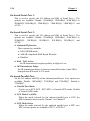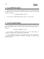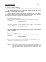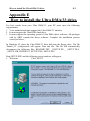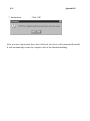
1
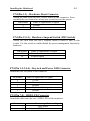
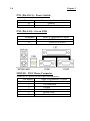
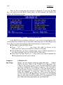
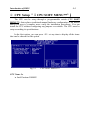
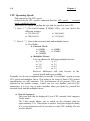
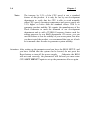
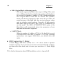
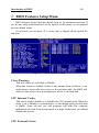
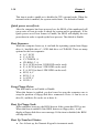
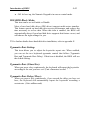
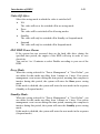
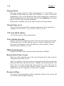
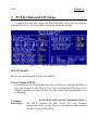
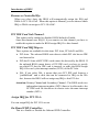
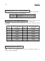
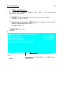
Pentium II Mainboard USER’S MANUAL Table of Contents Chapter 1 Introduction of LX6 Features ¬ Specifications.................................................. …….1-1 - Layout diagram .......................................................1-3 ® The system block diagram........................................1-4 Chapter 2 Installing the Mainboard ¬ Installing the Mainboard to the Casing ....................2-3 - Standard External Connectors .................................2-4 ® Jumper and Switches................................................2-9 ¯ Installation of the CPU ..........................................2-10 ° Installing System Memory ¡i DRAM Memory ¡j2-11 Chapter 3 Introduction of BIOS ¬ CPU Setup ¡i CPU SOFT MENU™¡j…………3-3 ® ¯ ° ± ² ³ ´ µ Standard CMOS Setup Menu ………………………3-7 BIOS Features Setup Menu ……………………….. 3-9 Chipset Features Setup Menu ………………………3-15 Power Management Setup Menu ………………….. 3-17 PCI & Onboard I/O Setup …………………………. 3-22 Load BIOS Defaults ……………………………….. 3-26 Load Setup Defaults ……………………………….. 3-26 Password Setting …………………………………… 3-27 IDE HDD Auto Detection ………………………….. 3-28 Chapter 4 Bus Master IDE Driver Part No:MN-100-2A0-71 Rev:1.00 Appendix A Quick Installation Appendix B General Discussion about HDD Installation Appendix C Technical Support Appendix D Flash BIOS User Instructions Appendix E How to install Ultra DMA/33 drive Appendix F How to install PCI Bridge Batch file Introduction of LX6 Chapter 1 Feature 1-1 Introduction of LX6 Feature The mainboard is designed for the new generation CPU. It supports the Intel CPU SLOT1(PentiumII), up to 1GB of memory, super I/O, and Green PC functions. The mainboard provides high performance for the server system and meets the requirements of the desktop system for multimedia in the future. ¬ Specifications 1. CPU l CPU SOFT MENU™ eliminates the need for jumpers or DIP switches needed to set CPU parameters l Employs switching type regulators to stabilize CPU operation l Supports 66, 75* and 83*MHz CPU external clock speeds l Supports Pentium® II 233 ~ 300 MHz processor cartridge 2. Chipset l l l l Intel 440LX chipset (82443LX and 82371AB) Supports Ultra DMA/33 IDE protocol Supports Advanced Configuration and Power Management Interface(ACPI) Accelerated Graphics Port connector supports AGP 66MHz/133MHz (Sideband) 3.3V device 3. Cache Memory l Level 1 and Level 2 cache built into Intel Pentium II processor card 4. Memory(DRAM) l Four 168-pin DIMM sockets support SDRAM and EDO DRAM modules l Supports up to 512MB (EDO DRAM up to 1GB) l ECC suppor 1-2 Chapter 1 5. System BIOS l Award Plug and Play BIOS supports APM, DMI, and ACPI 6. Multi I/O Functions l Floppy port supports up to 2.88MB, 3 mode floppy and LS-120 l Ultra DMA/33 bus master IDE supports up to 4 IDE devices l Built-in Standard/EPP/ECP parallel port connector l Two built-in 16550 fast UART compatible serial port connectors l Built-in PS/2 keyboard and PS/2 mouse port connectors l Built-in standard IrDA TX/RX header l Two built-in USB connectors 7. Miscellaneous l ATX form factor l One AGP slot, Four PCI slots and Three ISA slots l Reserved circuitry for LDCM feature l PC97 / PC98 Compliant l Board size: 304 * 204mm Note: All brand names and trademarks are the property of their respective owners. *Above 66MHz bus speed supported but not guaranteed due to the PCI specs. Introduction of LX6 Feature - Layout diagram Figure 1-1 Component Locations 1-3 1-4 Chapter 1 ® The System block diagram CPU-SLOT1 Control Address Data AGP SLOT PMC 82443LX Addr Cntrl Main Memory (DRAM) PCI BUS Control Address/Data USB1 PIIX4 PCI SLOT(s) PCI IDE HEADER USB2 ISA BUS ISA SLOT(s) Buffer KBC RTC Serial 83977F LPT IrDA X BUS Flash BIOS FDC Installing the Mainboard Chapter 2 2-1 Installing the Mainboard This LX6 mainboard not only provides all standard equipment for classic personal computers, but also provides great flexibility for meeting future upgrade demands. This chapter will introduce step by step all the standard equipment and will also present, as completely as possible future upgrade capabilities. This mainboard is able to support all Intel Pentium II processors now on the market. (For details, see specifications in Chapter 1.) This chapter is organized according the following features: Œ Installing the Mainboard to the Casing • Standard external connectors Ž Jumpers and switches • Presentation and Installing of the CPU. º Installing the system memory. NNNN Before proceeding with the installation Before installing the mainboard please be sure to turn off or disconnect the power supply unit. Before making any modifications to the hardware configuration of the mainboard, the power supply to any areas of the mainboard you plan to modify should be turned off to avoid unnecessary damage to the hardware. 2-2 Chapter 2 & User friendly instructions Our objective is to enable the novice computer user to perform the installation by themselves. We have attempted to write this document in a very clear, concise and descriptive manner to help overcome any obstacles you may face during installation. Please read our instructions carefully and follow them carefully step-by-step. Installing the Mainboard 2-3 ¬ Installing the Mainboard to the Casing Most computer cases will have a base on which there will be many mounting holes that allows the mainboard to be securely attached and at the same time, prevents short circuits. There are two ways to attach the mainboard to the base. lwith spacers lor with bolts In principle, the best way to attach the motherboard is with bolts, and only if you are unable to do this should you attach the board with spacers. Take a careful look at the mainboard and you will see many mounting holes on it. Line these holes up with the mounting holes on the base. If the holes line up, and there are screw holes this means you can attach the mainboard with bolts. If the holes line up and there are only slots, this means you can only attach the mainboard with spacers. Take the tip of the spacers and insert it into the slots. After doing this to all the slots, you can slide the mainboard into position aligned with the slots. After the mainboard has been positioned, check to make sure everything is OK before putting the casing back on. Note: If the mainboard has mounting holes, but don’t line up with the holes on the base and their are no slots to attach the spacers, don’t panic, you can still attach the spacers to the mounting holes. Just cut the spacers (along the dotted line) (the spacer may be a little hard so be careful of our hands). In this way you can still attach the mainboard to the base without worrying about short circuits. Computer Knowledge Why is it that Cyrix is always raised in relation to IBM in books? In fact, these two 6*86 CPUs (limited to the 6*86 series) are basically the same thing. Because Cyrix does not have its own production line, it has contracted IBM to manufacture their 6*86 CPUs for them. However, IBM has stipulated that the Cyrix CPUs they produce have both the Cyrix and IBM mark printed on it. 2-4 Chapter 2 - Standard External Connectors Inside the case of any computer several cables and plugs have to be connected. These cables and plugs are usually connected one-by-one to connectors located on the mainboard. You need to carefully pay attention to any connection orientation the cables may have and, if any, notice the position of the first pin of the connector. In the explanations that follow, we will describe the significance of the first pin. PN2(Pin 4-5-6-7) - Speaker Connector Attach the system speaker to connector PN2. Pin number 4 5 6 7 Name or significance of signal + 5VDC Ground Ground Speaker data Installing the Mainboard 2-5 PN2(Pin 1-2) - Hardware Reset Connector Attach the cable from the case’s Reset switch to this connector. Press and hold the reset button for at least one second to reset the system. Pin number Name or significance of signal 1 Ground 2 Reset input PN1(Pin 13-14) - Hardware Suspend Switch (SMI Switch) Attach the cable from the case’s suspend switch (if there is one) to this switch. Use this switch to enable/disable the power management function by hardware. Pin number 13 14 Name or significance of signal Ground Suspend signal PN1(Pin 1-2-3-4-5) - Keylock and Power LED Connector Attach the case’s keylock to the connector. Pin number 1 2 3 4 5 Name or significance of signal +5VDC No connection Ground Keylock inhibit signal Ground PN1(Pin 7-8) - HDD LED Connector Attach the cable from the case’s HDD LED to this connector. Pin number 7 8 Name or significance of signal LED power HDD active 2-6 Chapter 2 PN1 (Pin 10-11) - Power Switch Pin number 10 11 Name or significance of signal Ground Power Switch signal PN2 (Pin 9-10) - Green LED Pin number 9 10 Name or significance of signal LED Power Green LED Active MOUSE - PS/2 Mouse Connector Attach a PS/2 mouse to this 6-pin Din-connector. Pin number Name or significance of signal 1 Mouse data 2 No connection 3 Ground 4 +5VDC 5 Mouse clock 6 No connection Installing the Mainboard KB - PS/2 Keyboard Connector Attach a keyboard to this 6-pin Din-connector. Pin number Name or significance of signal 1 Keyboard data 2 No connection 3 Ground 4 +5VDC 5 Keyboard clock 6 No connection ATX PWR - ATX Power input Connector Caution: If power supply connectors are not properly attached to ATX PWR, the power supply or add-on cards may be damaged. Attach the connectors from the power supply to ATX PWR. Pin number 1 2 3 4 5 6 7 8 9 10 11 12 13 14 15 16 17 18 19 Name or significance of signal +3.3V +3.3V Ground +5V Ground +5V Ground Powergood +5V +12V +3.3V -12V Ground ON/OFF control signal Ground Ground Ground -5V +5V 2-7 2-8 Chapter 2 FAN1, FAN2 , FAN3 - DC-FAN Power Connector Pin number 1 2 3 Name or significance of signal Ground +12V Sense IR - IR Connector(Infrared) Pin number 1 2 3 4 5 6 7 8 9 10 Name or significance of signal +5V FIRRX IR_RX Ground IR_TX No connection CIRRX +5V No connection No connection I/O port connectors Name No. of pins Description IDE1 40 IDE channel 1 connector IDE2 40 IDE channel 2 connector FDC 34 Floppy disk connector LPT 25 Parallel port COM1 9 Serial port COM1 connector COM2 9 Serial port COM2 connector USB 8 Universal serial Bus Notes: *IDE1, IDE2 are high performance PCI IDE connectors. Up to four IDE interface devices are supported. Installing the Mainboard 2-9 ® Jumper and Switches You can set jumper switches on the mainboard to configure various hardware options. See Figure 1-1 for jumper locations. Throughout this section, the following symbols are used to indicate jumper settings. For 3-pin jumpers, the symbols below are used: Short Pins 1 and 2 with a jumper cap. Short Pins 2 and 3 with a jumper cap. For 2-pins jumpers, the following symbols are used: Place the jumper cap over the two pins of the jumper to Short the jumper. Remove the jumper cap to Open the jumper cap. Note: To avoid losing jumper caps, attach the removed jumper cap to one of the jumper pins. 2-10 Chapter 2 CCMOS 1 - CMOS Discharge Jumper Jumper CCMOS discharge CMOS memory. When you install the mainboard, make sure this jumper is set for Normal Operation(1-2). See the jumper below. Setting CCMOS Normal Operation (Default) Discharge CMOS ¯ Installation of the CPU The mainboard is equipped with a CPU-SLOT1 slot to accommodate Intel PentiumII CPU or above. The default clock rate setting for PentiumII CPU is 233MHz and depends on auto detect from BIOS. But there is a etter way to set up the menu. For details please refer the chapter 3 “Award BIOS Setup”. Installing the Mainboard 2-11 ° Installing System Memory The mainboard provides four 168-pin DIMM sites for memory expansion.. The DIMM socket supports 1Mx64(8MB), 2Mx64(16MB), 4Mx64(32MB), 8Mx64(64MB), 16Mx64(128MB), and 32Mx64(256MB) or double sided DIMM modules. Minimum memory size is 8MB and maximum memory size is 512 MB SDRAM and 1GB EDO. There are four banks of Memory on the system board. In order to create a memory array, certain rules must be followed. The following set of rules allows for optimum configurations. l The memory array is 64 or 72 bits wide. (Without parity or with parity) l Those modules can be populated in any order. l Support single and double density DIMMS. The following is the valid memory configuration: Bank Memory Module Bank0 8MB,16MB, 32MB,64MB, (DIMM1) 128MB Bank1 8MB,16MB, 32MB,64MB, (DIMM2) 128MB Bank3 8MB,16MB, (DIMM3) 32MB,64MB, 128MB Bank4 8MB,16MB, (DIMM4) 32MB,64MB, 128MB Total System Memory Total Memory 8MB ~ 256MB 2 8MB ~ 256MB 2 8MB ~ 256MB 1 8MB ~ 256MB 1 8MB ~ 1GB = Introduction of BIOS Chapter 3 3-1 Introduction of BIOS The BIOS is a program located on a Read-Only Memory chip on the mainboard. This program will not be lost when you turn the computer off. This program is also referred to as the boot program. It is the only channel for the hardware circuit to communicate with the operating system. Its main function is to manage the setup of the mainboard and interface cards parameters, including simple parameters such as time, date, hard disk drive, as well as more complex parameters such as hardware synchronization, device operating mode, CPU SOFT MENU™ techniques, setup of CPU voltage and speed. The computer will operate normally, or will operate at its best, only if all these parameters are correctly configured through the BIOS. M Don’t change the parameters inside the BIOS unless you know what you are doing The parameters inside the BIOS are used to setup the hardware synchronization or the device operating mode. If the parameters are not correct, they will produce errors, the computer will crash, and sometimes you will even not be able to boot the computer after it has crashed. We recommend that you do not change the parameters inside the BIOS unless you are familiar with them. If you are not able to boot your computer anymore, please refer to the section “Erase CMOS data” in Chapter 2. When you start the computer, it is controlled by the BIOS program. The BIOS first operates an auto-diagnostic for all the necessary hardware, configurates the parameters of the hardware synchronization, and detects all the hardware. Only when these tasks are completed does it give up control of the computer to the program of the next level, which is the operating system. Since the BIOS is the only channel for hardware and software to communicate, it will be the key factor to system stability, and to ensure that your system performs at its best. After the BIOS has achieved the auto-diagnostic and auto-detection operations, it will display the following message: PRESS DEL TO ENTER SETUP 3-2 Chapter 3 Three to five seconds after the message is displayed, if you press the Del key, you will access the BIOS Setup menu. At that moment, the BIOS will display the following message: Fig 3 BIOS Setup main menu In the BIOS Setup main menu of Figure 3, you can see several options. We will explain these options step by step in the following pages of this chapter, but let us first see a short description of the function keys you may use here: l Press Esc to quit the BIOS Setup. l Press ¡ô¡õ¡÷¡ö (up, down, left, right) to choose, in the main menu, the option you want to confirm or to modify. l Press F10 when you have completed the setup of BIOS parameters to save these parameters and to exit the BIOS Setup menu. l Press Page Up/Page Down or +/- keys when you want to modify the BIOS parameters for the active option. Computer knowledge CMOS DATA Maybe you have heard somebody saying that their CMOS DATA was lost. What is the CMOS? Is it important? The CMOS is the memory used to store the BIOS parameters that you have configured. This memory is passive. You can read its data, and you can also store data in it. But this memory has to be powered by a battery, in order to avoid any loss of its data when the computer is turned off. Since you may have to change the CMOS battery when it is out of power and indoing so, you will loose all CMOS data, therefore, we recommend that you write down all the parameters of your hardware, or to put a label with these parameters on your hard disk. Introduction of BIOS 3-3 ¬ CPU Setup ¡i CPU SOFT MENU™ ¡j The CPU can be setup through a programmable switch (CPU SOFT MENU™ ), that replaces traditional manual hardware configuration. This feature allows the user to complete more easily the installation procedures. You can install the CPU without configuring any jumpers or switches. The CPU must be setup according its specifications. In the first option, you can press <F1> at any time to display all the items that can be chosen for that option. Fig 3-1 CPU Name Is: ä Intel Pentium II MMX CPU SOFT MENU™ 3-4 Chapter 3 CPU Operating Speed: This option sets the CPU speed. In this field, the CPU speed is indicated like this: CPU speed (external clock x multiplier factor) Select the CPU speed according the type and the speed of your CPU. ¡i Note 1 ¡j For Intel Pentium II MMX CPUs, you can choose the following settings: ä 233 (66x3.5) ä 266 (66x4) ä 300 (66x4.5) ä 333 (66x5) ¡i Note 4 ¡j User define external clock and multiplier factor: ä User Define / External Clock: ä 60MHz ä 66MHz ä 75MHz ä 83MHz ä 100MHz / Multiplier Factor: You can choose the following multiplier factors: ä 2.0 ä 2.5 ä 3.0 ä 3.5 ä 4.0 ä 4.5 ä 5.0 ä 5.5 However, differences will exist because of the various brands and types available. Normally, we do not recommend that you use the “User Define” option to setup CPU speed and multiplier factor. This option is for setup of future CPUs whose specifications are still unknown. The specifications of all present CPUs are included in the default settings. Unless you are very familiar with all CPU parameters, it is very easy to make mistakes when you define by yourself the external clock and the multiplier factor. / Turbo Frequency: This item will only be displayed if your CPU external clock supports Turbo mode. The Turbo mode allows you to speed up the external clock by approximately 2.5%. This feature is used to verify the design flexibility. It is a very important tool for test units to verify CPU stability. Do not use this feature. Introduction of BIOS 3-5 ä Disable: CPU external clock is operating within the normal limits. ä Enable: CPU external clock is operating within the limits of the Turbo mode. Solution in case of booting problem due to invalid clock setup: Normally, if the CPU clock setup is wrong, you will not be able to boot. In this case, turn the system off than on again. The CPU will automatically use its standard parameters to boot. You can then enter BIOS Setup again and set up the CPU clock. If you can’t enter BIOS setup , you must try turning the system on a few times (3~4 times) and the system will automatically use its standard parameters to boot. You can then enter BIOS SETUP again and set up the new parameters. When you change your CPU: The mainboard have been designed in such a way that you can turn the system on after having inserted the CPU in the socket without having to configure any jumpers or DIP switches. But if you change your CPU, normally, you just have to turn off the power supply, change the CPU and then, set up the CPU parameters through CPU SOFT MENU™ . However, if the CPU brand and type is the same, and if the new CPU is slower than the old one, we offer you two methods to successfully complete the CPU change operation. Method 1: Setup up the CPU for the lowest speed for its brand. Turn the power supply off and change the CPU. Then turn the system on again, and set up the CPU parameters through CPU SOFT MENU. Method 2: Since you have to open the computer case when you change the CPU, it could be a good idea to use the CCMOS jumper to erase the parameters of the original CPU and to enter BIOS Setup to set up CPU parameters again. 3-6 Chapter 3 Note : The increase by 2.5% of the CPU speed is not a standard feature of this product. It is only for use by our development department to verify that the CPU is able to work normally when CPU speed, operating temperature and power supply are 2.5% higher or lower than the standard values. This is to guarantee product stability. We require the manufacturer of the Clock Generator to meet the demands of our development department and to add a TURBO Frequency feature used for testing purposes by our R&D department. Of course, you can use this feature to test the stability of your own system, but after you have tested the product, we recommend that you set it back to its normal value in order to guarantee system stability. Attention: After setting up the parameters and you leave the BIOS SETUP, and you have verified that the system can be booted, do not press the Reset button or turn off the power supply. Otherwise the BIOS will not read correctly, the parameters will fail and you must enter CPU SOFT MENU™ again to set up the parameters all over again. Introduction of BIOS 3-7 - Standard CMOS Setup Menu It is the basic configuration parameters of the BIOS. These parameters include the settings of date, hour, VGA card, FDD and HDD. Fig 3-2 l Standard CMOS Setup Menu Set up of HDD operating mode ¡i NORMAL, LBA, LARGE ¡j Since old operating systems were only able to support HDD whose capacity was not bigger than 528MB, any hard disk with more than 528MB was unusable. AWARD BIOS features a solution to this problem: you can, according to your operating system, choose three operating modes: NORMAL, LBA or LARGE. ä Normal mode: Standard normal mode supports hard disks of 528MB or less. This mode directly uses positions indicated by Cylinders (CYLS), Heads, and Sectors to access data. 3-8 Chapter 3 ä LBA (Logical Block Addressing) mode: LBA mode supports hard disk drives up to 8.4Giga. This mode uses a different method to calculate the position of disk data to be accessed. It translates Cylinders (CYLS), Heads and Sectors into a logical address where data are located. The Cylinders, Heads, and Sectors displayed in this menu do not reflect the actual structure of the hard disk, they are just reference values used to calculate actual positions. Currently, all high capacity hard disks support this mode, that’s why we recommend you use this mode. The HDD AUTODETECTION option in the Main Menu will automatically detect the parameters of your hard disk and the mode supported. ä LARGE Mode: When the number of cylinders (CYLs) of the hard disk exceeds 1024 and DOS is not able to support it, or if your operating system does not support LBA mode, you should select this mode. l FDD supporting 3 Mode: 3 Mode floppy disk drives (FDD) are 3 1/2” drives used in Japanese computer systems. If you need to access data stored in this kind of floppy, you must select this mode, and of course you must have a 3 Mode floppy drive. 2 For further information about HDD installation, refer to Appendix E. Introduction of BIOS 3-9 ® BIOS Features Setup Menu BIOS Features Setup Menu has already been set for maximum operation. If you do not really understand each of the options in this menu, we recommend you use default values. In each item, you can press <F1> at any time to display all the options for this item. Fig 3-3 BIOS Features Setup Virus Warning: This item can be set as Enable or Disable. When this feature is enabled, if there is any attempt from a software or an application to access the boot sector or the partition table, the BIOS will warn you that a boot virus is attempting to access to the hard disk. CPU Internal Cache: This item is used to Enable or to Disable the CPU internal cache. When the cache is set at Disable, it is much slower, so the default setting for this item is Enable. Some old and very bad programs will make the computer malfunction or crash if the system speed is to high. In that case, you should Disable this feature. CPU External Cache: 3-10 Chapter 3 This item is used to enable or to disable the CPU external cache. When the external cache is enabled, the system works faster. The default is Enable. Quick power on self test: After the computer has been powered on, the BIOS of the mainboard will run a series of tests in order to check the system and its peripherals. If the Quick power on self test feature is Enable, the BIOS will simplify the test procedures in order to speed up the boot process. The default is Enable. Boot Sequence: When the computer boots up, it can load the operating system from floppy drive A:, hard disk drive C:, SCSI disk drive or CD-ROM. There are many options for the boot sequence: ä A, C, SCSI ä C, A, SCSI ä C, CD-ROM, A ä CD-ROM, C, A ä D, A, SCSI (at least 2 IDE HDD can be used) ä E, A, SCSI (at least 3 IDE HDD can be used) ä F, A, SCSI (at least 4 IDE HDD can be used) ä SCSI, A, C ä SCSI, C, A ä A, SCSI, C ä LS120, C Swap Floppy Drive: This item can be set as Enable or Disable. When this feature is enabled, you don’t need to open the computer case to swap the position of floppy disk drive connectors. Drive A: can be set as drive B:, and drive B: can be set as drive A:. Boot Up Floppy Seek: When computer boots up, the BIOS detects if the system has FDD or not. When this item is enabled, if the BIOS detects no floppy drive, it will display a floppy disk drive error message. If this item is disabled, the BIOS will skip this test. Boot Up NumLock Status: ä On: At boot up, the Numeric Keypad is in numeric mode. Introduction of BIOS 3-11 ä Off: At boot up, the Numeric Keypad is in cursor control mode. IDE HDD Block Mode: This item can be set as Enable or Disable. Most of new hard disk drives (IDE drives) support multi-sector transfers. This feature speeds up hard disk drive access performance and reduces the time necessary to access data. When this item is enabled, the BIOS will automatically detect if your hard disk drive supports this feature or not, and will choose the right settings for you. 2 For further details about hard disk drive installation, refer to appendix E. Typematic Rate Setting: This item allows you to adjust the keystroke repeat rate. When enabled, you can set the two keyboard typematic control that follow (Typematic Rate and Typematic Rate Delay). If this item is disabled, the BIOS will use the default setting. Typematic Rate (Chars/Sec): When you press a key continuously, the keyboard will repeat the keystroke according to the rate you have set. (Unit: characters/second ¡^ Typematic Rate Delay (Msec): When you press a key continuously, if you exceed the delay you have set here, the keyboard will automatically repeat the keystroke according a certain rate. (Unit: milliseconds) 3-12 Chapter 3 Security Option: This option can be set to System or to Setup. After you have created a password through PASSWORD SETTING, this option will deny access to your system (System) or modification of computer setup (BIOS Setup) by unauthorized users. ä SYSTEM: When you choose System, a password is required each time the computer boots up. If the correct password is not given, the system will not start. ä SETUP: When you choose Setup, a password is required only when accessing the BIOS Setup. If you have not set a password in the PASSWORD SETTING option, this option is not available. Notice: Don’t forget your password. If you forget the password, you will have to open the computer case and clear all information in the CMOS before you can start up the system. But doing this, you have to reset all the options you had set up before. PCI /VGA Palette Snoop: This option allows the BIOS to preview VGA Status, and to modify the information delivered from the Feature Connector of the VGA card to the MPEG Card. This option can solve the display inversion to black after you have used the MPEG card. Delay IDE Initial: This item is using for support some old model or special type of hard disks or CDROMs . Because the BIOS may not detect those kinds of devices during system booting . OS Select For DRAM > 64MB: When the system memory is bigger than 64MB, the communication method between the BIOS and the operating system will differ from one operating system to another. If you use OS/2, select OS2; if you choose another operating system, select Non-OS2. Introduction of BIOS 3-13 Video BIOS Shadow: This option is used to define whether the BIOS on the video card uses shadow feature or not. You should set this option to Enable, otherwise the display performance of the system will greatly decrease. Shadowing address ranges (C8000-CBFFF Shadow): This option allows you to decide if the memory block (BIOS) of an interface card at the address C8000-CBFFF uses the shadow feature or not. If you have no interface card using this memory block, don’t enable this option. Shadowing address ranges (CC000-CFFFF Shadow): This option allows you to decide if the memory block (BIOS) of an interface card at the address CC000-CFFFF uses the shadow feature or not. If you have no interface card using this memory block, don’t enable this option. Shadowing address ranges (D0000-D3FFF Shadow): This option allows you to decide if the memory block (BIOS) of an interface card at the address D0000-D3FFF uses the shadow feature or not. If you have no interface card using this memory block, don’t enable this option. Shadowing address ranges (D4000-D7FFF Shadow): This option allows you to decide if the memory block (BIOS) of an interface card at the address D4000-D7FFF uses the shadow feature or not. If you have no interface card using this memory block, don’t enable this option. Shadowing address ranges (D8000-DBFFF Shadow): This option allows you to decide if the memory block (BIOS) of an interface card at the address D8000-DBFFF uses the shadow feature or not. If you have no interface card using this memory block, don’t enable this option. 3-14 Chapter 3 Shadowing address ranges (DC000-DFFFF Shadow): This option allows you to decide if the memory block (BIOS) of an interface card at the address DC000-DFFFF uses the shadow feature or not. If you have no interface card using this memory block, don’t enable this option. Computer knowledge SHADOW What is the SHADOW? The BIOS of standard video or interface cards is stored in ROM, and it is often very slow. With the Shadow feature, the CPU reads the BIOS on the VGA card and copies it into RAM. When the CPU runs this BIOS, the operation is speeded up. Introduction of BIOS 3-15 ¯ Chipset Features Setup Menu The Chipset Features Setup Menu is used to modify the contents of the buffers in the chipset on the mainboard. Since the parameters of the buffers are closely related to hardware, if the setup is not correct or false, the mainboard will become unstable or you will not be able to boot up. If you don’t know the hardware very well, use default values (use the LOAD SETUP DEFAULTS option). Fig 3-4 Chipset Features Setup You can use the arrow keys to move between the items. Use "PgUP", "PgDn", "+" and "-" to change the values. When you have finished setting up the chipset, press "ESC" to go back to the main menu. Auto Configuration: This option allows (Enable) or prevents (Disable) the BIOS from using default values for Auto Configuration. The BIOS default is Enable. ä When you select Enable, the BIOS will automatically use the values related to DRAM. You will not be able to set up the following options. ä When you select Disable, you can manually set up DRAM options. 3-16 Chapter 3 Attention:Unless you are very familiar with your computer and with the DRAM configuration and speed, we recommend you not change the DRAM options but enable this option. DRAM settings: The other DRAM settings are all closely related to hardware. If you do not understand this very well, don’t make any changes. Our BIOS is able to autodetect the characteristics of your DRAM and to choose the best settings. Memory Hole At 15M-16M: This option is used to free up the 15M-16M memory block. Some special peripherals need to use a memory bloc located between 15M and 16M, and this memory block has a size of 1M. We recommend that you disable this option. There are small differences in the chipset feature setup according to different mainboard models, but this has no influence upon performance. Our default setup should be the best one. That is the reason why we do not describe all the features of this menu. Introduction of BIOS 3-17 ° Power Management Setup Menu The difference between Green PCs and traditional computers is that Green PCs have a power management feature. With this feature, when the computer is powered on but inactive, the power consumption is reduced in order to save energy. When the computer operates normally, it is in Normal mode. In this mode, the Power Management Program will control the access to video, parallel ports, serial ports and drives, and the operating status of the keyboard, mouse and other device. These are referred to as Power Management Events. In cases where none of these events occur, the system enters the power saving mode. When one of the controlled events occurs, the system immediately returns to normal mode and operates at its maximum speed. Power saving modes can be divided into three modes according to their power consumption: Doze Mode, Standby Mode , and Suspend Mode. The four modes proceed in the following sequence: Normal Mode===> Doze Mode===> Standby Mode===> Suspend Mode The system consumption is reduced according the following sequence: Normal > Doze > Standby > Suspend 1. In the Main Menu, select "Power Management Setup" and press "Enter". The following screen is displayed: Fig 3-5 Power Management Setup Menu 3-18 Chapter 3 2. Use arrow keys to go to the item you want to configure. To change the settings, use "PgUP", "PgDn", "+" and "-". 3. After you have configured the Power Management feature, press “Esc” to go back to the Main Menu. We are now going to briefly explain the options in this menu: Power Management: Four options: ä User Define User Define defines the delay for accessing the power modes. ä Min Saving When the three saving modes are enabled, the system is set up for minimum power savings. Doze = 1 hour Standby = 1 hour Suspend = 1 hour ä Max Saving When the three saving modes are enabled, the system is set up for maximum power savings. Doze = 1 minute Standby = 1 minute Suspend = 1 minute PM Control by APM: Power Management is completely controlled by the APM. APM stands for Advanced Power Mangement, it is a power management standard set by Microsoft, Intel and other major manufacturers. Video Off Method: Three video off methods are available: "Blank", "V/H SYNC+Blank" and "DPMS". The default is "V/H SYNC+Blank". If this setting does not shut off the screen, select “Blank”. If your monitor and video card support DMPS standard, select “DPMS”. Introduction of BIOS 3-19 Video Off After: Select the saving mode in which the video is switched off. ä NA The video will never be switched off in no saving mode. ä Doze The video will be switched off in all saving modes. ä Standby The video will only be switched off in Standby or Suspend mode. ä Suspend The video will only be switched off in Suspend mode. IDE HDD Power Down: If the system has not accessed data on the hard disk drive during the specified time period, the engine of the HDD will stop in order to save electricity. You can set 1 to 15 minutes or select Disable according to your use of the HDD. Doze Mode: When the setting selected for "Power Management" is "User Define", you can define for this mode any delay from 1 minute to 1 hour. If no power management event occurs during this time period, meaning that computer is inactive during this period, the system will enter the Doze power saving mode. If this mode is disabled, the system will enter the next mode in the sequence (Standby or Suspend mode). Standby Mode: When the setting selected for "Power Management" is "User Define", you can define for this mode any delay from 1 minute to 1 hour. If no power management event occurs during this time period, meaning the computer is inactive during this period, the system will enter the Standby power saving mode. If this mode is disabled, the system will enter the next mode in the sequence (Suspend mode). 3-20 Chapter 3 Suspend Mode: When the setting selected for "Power Management" is "User Define", you can define for this mode any delay from 1 minute to 1 hour. If no power management event occurs during this time period, meaning the computer is inactive during this period, the system will enter the Suspend power saving mode. The CPU stops working completely. If this mode is disabled, the system will not enter the Suspend mode. Throttle Duty Cycle: This is used to specify the CPU speed in saving mode. Seven options are available: 12.5%, 25.0%, 37.5%, 50.0%, 62.5% or 75.0% . CPU Fan Off In Option: CPU fan can be turn off in suspend mode. Power Button Override: Support ACPI Power Button Over-ride. The user presses the power button for more then four seconds while the system is in the working state, then the system will transition to the soft-off(Power off by software). This is called the power button over-ride. IRQ8 Break Suspend : Support RTC alarm wake up from suspend function (via IRQ8). Reload Global Timer Events When one of the speficied occurs, the count down made for entry in power saving mode goes back to zero. Since the computer will enter a power saving mode only after an inactivity delay specified (time speficied for Doze, Standby and Suspend modes) and after it has no activity, during this time period, any event will cause the computer to re-count the time elapsed. Resume events are operations or signals that cause the computer to resume time counting. Resume by Ring: To connect a external modem with the onboard serial port, the system will be turned on when telephone ring-up. Introduction of BIOS 3-21 Resume by Alarm : RTC alarm can turn on the system . You can set date ( of month ) and time ( hour , minute , second ) . 3-22 Chapter 3 ± PCI & Onboard I/O Setup In this menu, you can change the INT# and IRQ of the PCI bus and the onboard I/O device, I/O port address and other hardware settings. Fig 3-6 PCI & Onboard I/O Setup PnP OS Install : Device resource assigned by PnP OS or BIOS. Force Update ESCD: If you want to clear ESCD data next time you boot up, and ask the BIOS to reset the settings for the Plug & Play ISA Card and the PCI Card, select Enabled. But the next time you boot up, this option will automatically be set as Disabled. Computer Knowledge ESCD (Extended System Configuration Data) The ESCD contains the IRQ, DMA, I/O Port, Memory information of the system. This is a specification and a feature specific to Plug & Play BIOS. Introduction of BIOS 3-23 Resources Controlled By: When you select Auto, the BIOS will automatically assign the IRQ and DMA to PCI / ISA PnP . When this option is Manual, you can choose which IRQ or DMA can assign to PCI / ISA PnP . PCI IDE Card 2nd Channel: This option can be enabled or disabled. BIOS default is Enable. Since this channel uses IRQ15, if you want to use this channel, you have to enable this option to make the BIOS assign IRQ15 to this channel. PCI IDE Card IRQ Map to: Three options are available for this item: PCI Auto, PCI-slotX and ISA. ä PCI-Auto: The onboard BIOS auto-detects which PCI slot has an IDE card inserted in. ä PCI-slotX: Some old PCI IDE cards cannot be detected by the BIOS. If the onboard BIOS cannot detect a PCE IDE card, you have to specify on which PCI slot the IDE card is inserted, to make the BIOS assign IRQ14 for use by the interrupt number (INT#) of this PCI slot. ä ISA: If you select ISA, it means that your PCI IDE card features a “paddleboard” and a cable that can be connected to IRQ on the ISA slot, because the BIOS will not assign any IRQ to this PCI slot. Attention:Primary Channel and Secondary Channel : The BIOS needs two independent interrupt number (INT#) lines to be allocated to the PCI IDE card. Be careful not to choose twice the same interrupt number (INT#). Assign IRQ for PCI VGA : You can assign IRQ for PCI VGA or not . On Board FDD Controller: This is to Enable or Disable the Onboard FDD Controller. 3-24 Chapter 3 On board Serial Port 1: This is used to specify the I/O address and IRQ of Serial Port 1. Ten options are available: Disable, 3F8h/IRQ4, 2F8h/IRQ3, 3E8h/IRQ4 or 2E8h/IRQ3.3F8h/IRQ10, 2F8h/IRQ11, 3E8h/IRQ10, 2E8h/IRQ11, and AUTO. On board Serial Port 2: This is used to specify the I/O address and IRQ of Serial Port 2. Ten options are available: Disable, 3F8h/IRQ4, 2F8h/IRQ3, 3E8h/IRQ4 or 2E8h/IRQ3. 3F8/IRQ10, 2F8/IRQ11, 3E8/IRQ10, 2E8/IRQ11, and AUTO. / Onboard IR function: Three options are available: ä IrDA (HPSIR)mode. ä ASK IR (Amplitude Shift Keyed IR)mode. ä Disabled. / RxD , TxD Active: Set IR transmission/reception polarity as High or Low. / IR Transmission Delay: Set IR transmission delays 4 character-time(40 bit-time) when SIR is changed form RX mode to TX mode. On board Parallel Port: Set the I/O address and IRQ of the onboard parallel port. Four options are available: Disable, 3BCh/IRQ7, 278h/IRQ5 and 378h/IRQ7. Default is 378h/IRQ7. / Parallel Port Mode: Can be set as ECP, EPP , ECP+EPP, or Normal (SPP) mode. Default is Normal (SPP) mode. / ECP Mode Use DMA: When the mode selected for the onboard parallel port is ECP, the DMA channel selected can be Channel 1 or Channel 3. / EPP Mode Select: When the mode selected for the onboard parallel port is EPP, two EPP version options are available: EPP1.7 or EPP1.9 . Introduction of BIOS 3-25 On board IDE-1 Controller: Onboard PCI IDE 1 controller can be set as Enable or Disable. / Master drive PIO Mode: ä Auto: the BIOS can auto-detect the PIO mode of the HDD in order to set its data transfer rate. (Default) ä Mode 0~Mode 4: User can specify the PIO mode of the HDD in order to set its data transfer rate. / Slave drive PIO Mode: ä Auto: the BIOS can auto-detect the PIO mode of the HDD in order to set its data transfer rate. (Default) ä Mode 0~Mode 4: User can specify the PIO mode of the HDD in order to set its data transfer rate. On board IDE-2 Controller: The onboard IDE-2 controller can be set at Enable of Disable. / Master drive PIO Mode: ä Auto: the BIOS can auto-detect the PIO mode of the HDD installed in order to set its data transfer rate. (Default) ä Mode 0~Mode 4: User can specify the PIO mode of the HDD in order to set its data transfer rate. / Slave drive PIO Mode: ä Auto: the BIOS can auto-detect the PIO mode of the HDD installed in order to set its data transfer rate. (Default) ä Mode 0~Mode 4: User can specify the PIO mode of the HDD in order to set its data transfer rate. MODE 0~4 reflects the HDD data transfer rate. The higher the MODE value is, the better is the HDD data transfer rate. But it does not mean that you can select the highest MODE value just as you like, you first have to be sure that your HDD supports this MODE, otherwise the hard disk will not be able to operate normally. 2 For further information about HDD installation, refer to Appendix E. 3-26 Chapter 3 ² Load BIOS Defaults BIOS defaults are the reference settings that allow your system to work at a comparatively low performance. When you choose the option, the following message is displayed: “Load BIOS Defaults (Y/N)? N” If you want to use BIOS default values, press “Y”, than <Enter>. ³ Load Setup Defaults Setup defaults are the settings that allow your system to operate at its highest performance. When you choose this option, the following message is displayed: “Load Setup Defaults (Y/N)? N” If you want to use BIOS Setup default values, press “Y”, than <Enter> to complete the loading of the settings for best performance. You should first load the best settings, than enter the CPU Soft Menu to set up CPU parameters, otherwise the BIOS will replace set parameters by default parameters. Introduction of BIOS 3-27 ´ Password Setting This option allows you to set a password required to start the system (System) or to access to the BIOS (Setup). After you have set a password through the PASSWORD SETTING option, you can enter the Security Option in the “BIOS Features Setup Menu” to select the security level in order to prevent any unauthorized access. Password setting procedure: When you choose the Password setting option, the following message is displayed: “Enter Password:“ Type your password. When complete, press <Enter>. The following message is displayed: “Confirm Password:“ Type your password again. When complete, press <Enter>. The password setting is completed. Password clearing procedure: When you select the Password setting option, the following message is displayed: “Enter Password:“ Press <Enter>, the message “Password Disable” is displayed. Press a key. The password clearing procedure is completed. Notice: Do not forget your password. If you forget it, you will have to open the computer case, clear the contents of the CMOS, and boot the system up again. But doing this, you must reset all your settings. 3-28 Chapter 3 µ IDE HDD Auto Detection After you have installed the hard disk, in old systems, you had to know the hard disk specifications, such as the number of cylinders, heads and sectors, and to enter the relevant information into the hard disk information section. If the CMOS data were erased, and you had forgotten the hard disk specifications, it was a great problem. But now, you can use this option to autodetect the hard disk type and specifications, and the BIOS will automatically detect all the relevant information and place them in the Hard Disk data section of the Standard CMOS Setup Menu, in order to allow you to use your hard disk. Bus Master IDE Driver 4-1 Chapter 4 Bus Master IDE Driver The Intel PIIX4Bus Master IDE is now include in the mainboard. OS Support:Windows 95, Windows NT 3.5/3.51/4.0, OS/2 V2.x & Warp 3.0 Installation:Each OS has different install procedure, please check README.TXT file under each OS’s directory. 4-2 Chapter 4 Quick Installation Appendix A A-1 Quick Installation Appendix A will give you a simplified installation procedure, in order to allow you to install tour mainboard quickly and correctly. If you need further information or if you need to change some other settings, read from Chapters 1. Installing the CPU: Lift up the lever of the CPU socket, insert your CPU on the socket, and lower the lever back in position. Don’t worry, if you don’t respect the correct orientation, you will not be able to insert the CPU. Adjusting CPU voltage and speed: According to your CPU speed, set up the CPU in the CPU SOFT MENU™ of the BIOS SETUP. Installing DRAM: DIMM1 ~ DIMM4 Installing FDD: FDC- Connect one end of the 34-pin cable that comes with the drive to the FDD connector, and the other end of the cable to the FDC pin connector on the mainboard. Note: Be sure that the red line on the cable connects to the first pin of the connectors. A-2 Appendix A Installing HDD: IDE1- Connect one end of the 40-pin cable that comes with the drive to the HDD connector, and the other end to IDE1 pin connector on the mainboard. Note: Be sure that the red line on the cable connects to the first pin of the connectors. Installing CD-ROM Drive: IDE2- Connect one end of the 40-pin cable that comes with the drive to the CD-ROM connector, and the other end to the IDE2 pin connector on the mainboard. Note: Be sure that the red line on the cable connects to the first pin of the connectors. Watch the pin position and the orientation PN1 - There is a specific orientation for pin 1 to pin 5. Insert the five-threads keylock cable into correct pins of connector on the mainboard. Installing Keylock connector: Pin number 1 2 3 4 5 Name of the signal or signification +5VDC No connection Ground Keyboard inhibit Signal Ground Watch the pin position and the orientation PN1 - There is a specific orientation for pin 7 and pin 8. Connect the twothreads IDE LED connector to the connector on mainboard. Installing HDD LED connector: Pin number 7 8 Name of the signal or signification HDD LED signal ¡i LED Cathode ¡j HDD LED signal ¡i LED Anode ¡j Quick Installation A-3 Installing Suspend switch connector: PN1 - There is a specific orientation for pin 10 and pin 11. Connect the two-threads suspend switch connector of the computer case to correct pins of connector on the mainboard. You can ignore this connector since most of computer cases do not support this feature (the mainboard itself supports it). Pin number 14 13 Sleep LED connector: Connect the two-threads Pin number 9 10 Name of the signal or signification Suspend signal Ground PN2 - This connector has a specific orientation. LED connector on the mainboard. Name of the signal or signification LED’s Cathode LED’s Anode Installing speaker connector: PN2 - There is no specific orientation for pin 4 to pin 7. Connect the four-threads speaker cable to the PN2 connector pins on the mainboard. Pin number 4 5 6 7 Name of the signal or signification +5VDC Ground Ground Sound Signal A-4 Appendix A Installing Power ON/OFF switch connector : PN1 : Connect the two- threads switch connector on the mainboard. Pin number Name of the signal or signification 11 Power on/off 10 Ground Watch the pin position and the orientation ATXPWR - Connect the power supply unit to the correct connectors on the mainboard. Installing ATX Power input connector: Pin number 1 2 3 4 5 6 7 8 9 10 Name of the signal or signification +3.3VDC +3.3VDC Ground +5VDC Ground +5VDC Ground POWERGOOD +5VDC +12VDC Pin number 11 12 13 14 15 16 17 18 19 20 Name of the signal or signification +3.3VDC -12VDC Ground PS_ON Ground Ground Ground -5VDC +5VDC +5VDC Installing Keyboard connector: KB1 - There is an orientation pin. Connect your keyboard connector to connector on the mainboard. Quick Installation A-5 Installing PS2 Mouse: Mouse - There is an orientation pin. Connect your mouse connector to connector on the mainboard. Installing CPU Fan Power connector: FAN - There is a specific orientation. Connect the three-threads CPU Fan power cable to the Fan connector on the mainboard. CPU FAN/FAN2/FAN3 Pin number Name of the signal or signification 1 Sensor 2 +12V 3 Control on/off Adjusting other jumpers: Some jumpers are reserved for future functions or are not to be adjusted in normal operation. Adjust them according to the following recommendations. CCMOS ¡G Put jumper on pin 1 and pin 2. BIOS Setup: Parameters and CPU settings After you have followed the steps described above and completed the installation, when you power the computer on, you will see the following message displayed PRESS DEL TO ENTER SETUP Press immediately Del key to enter BIOS Setup. Select Load Setup Defaults, than enter CPU Soft Menu to set CPU parameters. A-6 Appendix A General Discussion about HDD Installation Appendix B B-1 General Discussion about HDD Installation Most of the present HDDs use IDE interface. Installing an IDE hard disk does not require a huge amount of intelligence like installing the driver for a SCSI hard disk, but this means that the user often must install the hard disk by himself and cope with all the problems he may encounter. Here, we will try to help you solve these possible problems. The data stored in the hard disk are accessed through a chipset located on the mainboard. You probably often hear about the PIO mode, Master mode or DMA mode of HDD. These modes reflect the way data is transferred from and to the IDE drive and the mainboard. What is the PIO mode? When the system needs to access hard disk data, the CPU delivers input/output (I/O) orders through the chipset on the mainboard to the hard disk drive, and than puts these data into the system memory. This is the PIO mode. What is the Master mode? When the system needs to access hard disk data, these data are directly accessed from the hard disk by the chipset on the mainboard (using a DMA or a PIO mode), and then the data is put into the memory. In this case, the CPU does not participate in the data transfer. What is the DMA mode? Usually, DMA mode refers to accessing the hard disk data by the chipset, it does not refers to data transfer mode. Here are some examples of data transfer rates for IDE HDD with PIO interface: PIO Mode 0 The fastest data transfer rate reaches 3.3Mbyte/sec PIO Mode 1 The fastest data transfer rate reaches 5.2Mbyte/sec PIO Mode 2 The fastest data transfer rate reaches 8.3Mbyte/sec PIO Mode 3 The fastest data transfer rate reaches 11.1Mbyte/sec PIO Mode 4 The fastest data transfer rate reaches 16.6Mbyte/sec B-2 Appendix B The higher the MODE value is, the best is the hard disk data transfer rate. But this does not mean that you can select the highest mode value as you like. You must be sure that your hard disk supports that type of fast data transfer, otherwise your hard disk will not be able to operate correctly. Here are some examples of data transfer rates for IDE HDD with DMA mode: DMA Mode 0 The fastest data transfer rate reaches 4.16Mbyte/sec DMA Mode 1 The fastest data transfer rate reaches 13.3Mbyte/sec DMA Mode 2 The fastest data transfer rate reaches 16.6Mbyte/sec Usually, PIO mode means that the hard disk data are accessed by the CPU through the chipset and placed into memory, and the chipset is using PIO mode to access hard disk data. MASTER mode means that hard disk data are accessed by the chipset, and that the chipset places the data into memory. The chipset is using DMA or PIO mode to access data stored in the hard disk drive. The Master mode can reduce the CPU load, especially in a Multi-task environment. This can help system performance. General Discussion about HDD Installation B-3 Installing a hard disk: In the Standard CMOS Setup Menu, ♦ Primary means the first connector on the mainboard, that is, connector IDE1 on our mainboard. ♦ Secondary means the second connector on the mainboard, that is, connector IDE2 on our mainboard. ♦ Two HDDs can be connected to the each connector: The first HDD is referred to as Master, The second HDD is referred to as Slave. The Master or Slave status of the hard disk drive is set on the hard disk itself. Refer to the hard disk drive manual. Installing one HDD : The red line on the connection cable must be lined up with pin 1 on the connector. Be sure that your hard disk drive is set at Master. Actually, most hard disk drives are set at Master as a default, so you don’t need to adjust any setting. Just connect one end of the 40 pin cable on the drive connector, and the other end to connector IDE1 on the mainboard. Installing one HDD + one CD-ROM drive: The red line on the connection cable must be lined up with pin 1 on the connector. Method 1: Set the HDD at Master, and the CD-ROM drive at Slave. Connect one connector of the 40-pin cable to the hard disk, another one to the CD-ROM drive, and the other end to connector IDE1 on the mainboard. Method 2: Set the HDD as Master and connect one end of the 40-pin cable to the HDD, and the other end to connector IDE1 on the mainboard. You can ignore the setting of the CD-ROM drive, just connect one end of the 40-pin cable to the CD-ROM drive, and the other end to connector IDE2 on the mainboard. We recommend you use this kind of connection, which has no influence on HDD speed. B-4 Appendix B Installing two HDDs: The red line on the connection cable must be lined up with pin 1 on the connector. Method 1: Set the hard disk drive used for boot up at Master, and the other drive at Slave. Connect one of the connectors of the 40-pin cable to the first drive, another connector to the second drive, and the other end of the cable to connector IDE1 on the mainboard. Method 2: Set the hard disk drive used for boot up at Master, connect one end of the 40-pin cable to the drive, and the other end to connector IDE1 on the mainboard. Set the other hard disk drive at Master, connect one end of the 40-pin cable to the drive, and the other end to connector IDE2 on the mainboard. Installing two HDDs + one CD-ROM drive: The red line on the connection cable must be lined up with pin 1 on the connector. Method 1: Set the hard disk drive used for boot up as Master, set the other HDD at Slave, connect one connector of the 40-pin cable to the first drive, another connector to the second drive, and the other end of the cable to connector IDE1 on the mainboard. You can ignore the setting of the CD-ROM drive. Connect one end of the 40-pin cable to the drive, and the other end to connector IDE2 on the mainboard. We recommend you use this method, which has no influence on HDD speed. Method 2: Set the hard disk drive used for boot up at Master, connect one end of the 40-pin cable to the drive, and the other end to connector IDE1 on the mainboard. Set the other hard disk drive at Master, and be sure that the CD-ROM drive is set at Slave. Most of CD-ROM drives are set at Slave as a default, so you will normally not have to set the CD-ROM drive. After you have verified the settings, connect one connector of the 40-pin cable to the HDD, another connector to the CD-ROM drive, and the other end of the cable to connector IDE2 on the mainboard. General Discussion about HDD Installation B-5 Installing three HDDs: The red line on the connection cable must be lined up with pin 1 on the connector. Method 1: Set the hard disk drive used for boot up at Master, set the second drive at Slave. Connect one connector of the 40-pin cable to the first drive, another connector to the second drive, and the other end of the cable to connector IDE1 on the mainboard. Set the other (the third) drive at Master, and connect one end of the 40-pin cable to the drive, and the other end to connector IDE2 on the mainboard. Method 2: Set the hard disk drive used for boot up at Master, and connect one end of the 40-pin cable to the drive and the other end to connector IDE1 on the mainboard. Set another drive (the second drive) at Master and the third drive at Slave, connect one connector of the 40-pin cable to the second drive, another connector to the third drive, and the other end of the cable to connector IDE2 on the mainboard. Installing three HDDs + one CD-ROM drive: The red line on the connection cable must be lined up with pin 1 on the connector. Set the hard disk drive used for boot up at Master, set another HDD (the second) at Slave, connect one connector of the 40-pin cable to the first drive, another connector to the second drive, and the other end of the cable to connector IDE1 on the mainboard. Set the third hard disk drive at Master, set the CD-ROM drive at Slave, connect one connector of the 40-pin cable to the third HDD, another connector to the CD-ROM drive, and the other end of the cable to connector IDE2 on the mainboard. BIOS Setup: ♦ If all your HDDs are new, you can use the IDE HDD Auto Detection option in the CMOS to autodetect the parameters of all your drives. You don’t need to set any hard disk parameter. ♦ If one or several of your HDDs are old, and if you don’t know their parameters, and you want to reconfigure your drives, you can also use the IDE HDD Auto Detection option in the CMOS to autodetect the drives parameters. B-6 Appendix B ♦ If one or several of your HDD are old, and if you don’t want to erase the data stored in your drives, you will have to remember the parameters (Type, Cylinders, Heads, Sectors, Mode) of the drive(s) you don’t want to erase. After you have used the IDE HDD Auto Detection option in the CMOS, enter the Standard CMOS Setup Menu to change the settings of the related hard disk drive. Software use: The basic step in using a hard disk drive is to make a HDD Low Level Format, than run FDISK, and than FORMAT the drive. Most of present HDD have already been subjected to low level format at the factory, so you probably can skip this operation. Boot with a bootable floppy disk, then enter FDISK. Using FDISK: (DOS command) This command is found in the DOS disks. FDISK is a tool used to organize and to partition the hard disk. The hard disk must have been partitioned before use. You can create one unique partition on the hard disk, or create several partition and use a different Operating System on each partition. Just don’t forget that you have to specify an Active partition, otherwise your hard disk will not be bootable. For further information about FDISK, refer to the FDISK section in the DOS user’s manual. After you have partitioned the hard disk with FDISK, the system will reboot automatically. Boot from a system floppy disk, and type FORMAT C:/S Using FORMAT: (DOS command) This command is found in the DOS disks. FORMAT is used to format the hard disk. The HDD have to be formatted before use. Don’t forget to add /S after C:, otherwise the hard disk will not be bootable after formatting. Technical Support Appendix C C-1 Technical Support L When you have a problem during operation... In order to help our technical support personnel to quickly find out what is the problem of your mainboard and to give you the answers you need, before filling in the technical support form, eliminate any peripheral that is not related to the problem, and indicate on the form the key peripherals. Fax this form to your dealer or to the company where you bought the hardware in order to benefit from our technical support. (You can refer to the examples given below.) 2 Example 1: With a system including: mainboard (with CPU, DRAM, COAST...) HDD, CD-ROM, FDD, VGA CARD, MPEG CARD, SCSI CARD, SOUND CARD..., after the system is assembled, if you cannot boot up, check the key components of the system using the procedure described below. First remove all interface cards except the VGA card and try to reboot. F If you still cannot boot up: Try installing another brand/model VGA card and see if the system will start. If it still does not start, note the VGA card model, mainboard model, Bios identification number, CPU on the technical support form (refer to main instructions), and describe the problem in the problem description space provided. F If you can boot up: Insert back the interface cards you have removed one by one and try to start the system each time you insert a card, until the system doesn’t start anymore. Keep the VGA card and the interface card that causes the problem inserted on the mainboard, remove any other card or peripheral, and start again. If you still cannot start, note down the information related to both cards in the Add-On Card space provided, and don’t forget to indicate the mainboard model, version, BIOS identification number, CPU (refer to main instructions), and give a description of the problem. C-2 Appendix C 2 Example 2: With a system including the mainboard (with CPU, DRAM, COAST...) HDD, CD-ROM, FDD, VGA CARD, LAN CARD, MPEG CARD, SCSI CARD, SOUND CARD, after assembly and after having installed the Sound Card Driver, when you restart the system, when it runs the Sound Card Driver, it resets automatically. This problem may be due to the Sound Card Driver. During the Starting DOS… procedure, press SHIFT (BY-PASS) key, to skip CONFIG.SYS and AUTOEXEC.BAT; edit CONFIG.SYS with a text editor, and in front on the line that loads the Sound Card Driver, add a remark REM, in order to disable the Sound Card Driver. See the example below. CONFIG.SYS: DEVICE=C:\DOS\HIMEM.SYS DEVICE=C:\DOS\EMM386.EXE HIGHSCAN DOS=HIGH,UMB FILES=40 BUFFERS=36 REM DEVICEHIGH=C:\PLUGPLAY\DWCFGMG.SYS LASTDRIVE=Z Restart the system. If the system starts and does not reset, you can be sure that the problem is due to the Sound Card Driver. Note down the Sound Card model, mainboard model, BIOS identification number on the technical support file (refer to main instructions), and describe the problem in the space provided. JJJ Technical Support C-3 $$ Main instructions... To fill in this “Technical Support Form”, refer to the step-by-step instructions given below: *1. MODEL: Note the model number given in your user’s manual. Example: PT5R2, PR5R2... *2. Mainboard model number (REV): Note the mainboard model number labeled on the mainboard as “REV:*.**”. Exemple: REV:2.11 *3.BIOS ID# : See below: Example: “3R” is the “BIOS” ID number “2A59GA1EC” is the “BIOS” part number C-4 Appendix C 4. DRIVER REV: Note the driver version number indicated on the DEVICE DRIVER disk as “Release *.**”. Example: < IDE Device Driver Drivers Diskette Release 1.09A Release 1.09A *5. OS/APPLICATION: Indicate what are the operating system and the applications your are running on the system. Example: MS-DOS 6.22, Windows 3.1.... *6. CPU: Indicate the brand and the speed (MHz) of your CPU. Example: (A) In the “Brand” space, write “Intel”, in the “Specifications” space, write “150MHz”¡C (B) In the “Brand” space, write “Cyrix”, in the “Specifications” space, write “P166+”¡C (C) In the “Brand” space, write “AMD”, in the “Specifications” space, write “P75”. 7. HDD: Indicate the brand and specifications of your HDD(s), specify if the HDD is using ¨IDE1 or ¨IDE2. If you know the disk capacity, indicate it and check (“ü”) “ ”; in case you give no indication, we will consider that your HDD is “þIDE1” Master. Example: In the “HDD” space, check the box, in the Brand space, write “Seagate”, in the Specifications space, write “ST31621A (1.6GB)”. 8. CD-ROM Drive: Indicate the brand and specifications of your CDROM drive, specify if it uses ¨ IDE1 or ¨IDE2 ¡A and check (“ü”) “ ”; in case you give no indication, we will consider that your CDROM is “þIDE2” Master. Example: In the “CD-ROM drive” space, check the box, in the Brand space, write “Mitsumi”, in the Specifications space, write “FX400D”. Technical Support C-5 9. System Memory (DRAM): Indicate the brand and specifications (SIMM/DIMM) of your system memory. Examples: In the Brand space, write “Panasonic”, in the Specifications space, write “SIMM-FP DRAM 4MB-06”. Or, in the Brand, write “NPNX”, in the Specifications space, write “SIMM-EDO DRAM 8MB-06”. Or, in the Brand space, write “SEC”, in the Specifications space, write “DIMM-S DRAM 8MB-G12”. 10. COAST: Indicate the brand and specifications of your COAST. Example: In the Brand space, write “Winbond”, in the Specifications space, write “256KB” or “W25P010AF-8”¡C 11. ADD-ON CARD: Indicate which add-on cards you are “absolutely sure” are related to the problem. If you cannot identify the problem origin, indicate all the add-on cards inserted into your system. Note: Items between the “*” are absolutely necessary. C-6 Appendix C Technical Support C-7 & Technical Support Form ( Phone #: /Fax #: BIOS ID # * DRIVER REV Company name: J Contact: Model * Mainboard model no. OS/Application * Hardware name C.P.U HDD CD-ROM Drive * IDE1 IDE2 IDE1 IDE2 System Memory (DRAM) COAST ADD-ON CARD ? Problem Description: Brand Specifications C-8 Appendix C Appendix D Example 1 Flash BIOS User Instructions To update BIOS and create a backup of the current system BIOS execute this command: AWDFLASH NEWBIOS /Py SAVEBIOS /Sy Example 2 To update BIOS, create a backup of current system BIOS, and clear the CMOS, execute this command: AWDFLASH NEWBIOS SAVEBIOS /CC Example 3 To update BIOS and clear PnP settings execute this command: AWDFLASH NEWBIOS /Sn /CP Example 4 To make a backup of the current system BIOS execute the following command: AWDFLASH NEWBIOS /Pn SAVEBIOS Notes: “NEWBIOS” indicates file name for the new BIOS which can be downloaded from our website at http://www.abit.com.tw (user can choose a different file name in place of NEWBIOS). “SAVEBIOS” indicates the filename of the old system BIOS (user can choose a different file name in place of SAVEBIOS). D-2 Appendix D Explanation of parameter names: /CC: Clears CMOS data /CP: Clears PnP data Remarks: ¬ When executing AWDFLASH.EXE, do not run HIMEM.SYS and EMM386.EXE in the CONFIG.SYS. - Please take the following actions to solve problems caused by power shortage or other other unpreventable malfunctions during BIOS update that lead to update failure. First, it is strongly suggested that you format a disk that can boot your computer before you update your BIOS. If the above mentioned problem occurs during BIOS update you will be able to use this disk to automatically execute a BIOS update. The content of the disk should be the following: a. Startup system files (COMMAND.COM, MSDOS.SYS, IO.SYS...) b. AWDFLSH.EXE c. The NEWBIOS file which can be downloaded from ABIT’s website. d. AUTOEXEC.BAT, which has the following content: A:\AWDFLASH NEWBIOS /Py /Sn /CC . ® When a version of BIOS that is for the incorrect mainboard model the following message will appear: “The program file’s part number does not match with your system!” How to install the Ultra DMA/33 drive. E-1 Appendix E How to install the Ultra DMA/33 drive. For best results from your Ultra DMA/33, your PC must meet the following requirements: 1. Your motherboard must support the Ultra DMA/33 interface. 2. It must support the Ultra DMA hard drive. 3. It must support the operating system’s Ultra DMA driver software. All packages sold by ABIT contain this driver software. Complete the installation process exactly as below; In Windows 95, place the Ultra DMA/33 diver disk into the floppy drive. The file ‘Bmide_95’ (compressed) will appear. Run this file. The file will automatically decompress the following files; README.TXT, _INST32I.EX_, _SETUT.DLL, _SETUP.LIB, PIIXDRV.Z, SETUP.EXE, SETUP.INS Run SETUP.EXE and the following seven windows will appear 1. Welcome: Click ‘NEXT’ E-2 2. License: 3. Question: Appendix E Notebook - close the view Click ‘Yes’ How to install the Ultra DMA/33 drive. 4. Select Components: Click ‘INSTALL 5.Question: Click ‘Yes’ 6. Question: Click ‘Yes’ E-3 E-4 7. Information: Appendix E Click ‘OK’ After previous instructions have been followed, the driver will automatically install. It will automatically restart the computer after it has finished installing. How to install the PCI Bridge Batch File F-1 Appendix F How to install the PCI Bridge Batch File. First of all, you may ask, ‘why do I have to install it?’. Well, the main reason is that Windows 95 has no way of recognising the 440LX chip set. Because of this, the error, ‘?PCI Bridge’ will appear in the system content (see picture below). To get rid of this from the system content, the batch file must be run. The file can be found at our web-site at <http://www.abit.com.tw/html.loadut.htm F-2 Appendix F or http://www.abit.com.tw/html/cloadut.html/>. Just download PCI_TX.EXE and run it. It will automatically decompress and you will see 26 icon files appear in Windows 95. After you open the file, run AbitTX and a view will appear (see picture below). Click on ‘OK’. How to install the PCI Bridge Batch File F-3 After the process has been completed another view will appear (see picture below). Again, click on ‘OK’. After clicking on ‘OK’, the driver will automatically install and restart the computer after it has finished. F-4 Appendix F