1
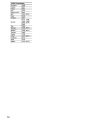
Contents
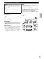
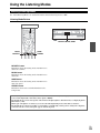
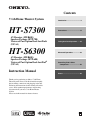
7.1ch Home Theater System
HT-S7300
AV Receiver (HT-R680)
Speaker Package (HTP-780)
Universal Port Option Dock for iPod®
(UP-A1)
HT-S6300
AV Receiver (HT-R680)
Speaker Package (HTP-680)
Universal Port Option Dock for iPod®
(UP-A1)
Introduction ...................................2
Connections.................................14
Turning On & Basic Operations ......24
Advanced Operations .................38
Controlling iPod & Other
Components............................56
Instruction Manual
Others...........................................64
Thank you for purchasing an Onkyo 7.1ch Home
Theater System. Please read this manual thoroughly
before making connections and plugging in the unit.
Following the instructions in this manual will enable
you to obtain optimum performance and listening
enjoyment from your new 7.1ch Home Theater
System.
Please retain this manual for future reference.
En
Introduction
WARNING:
TO REDUCE THE RISK OF FIRE OR ELECTRIC
SHOCK, DO NOT EXPOSE THIS APPARATUS TO
RAIN OR MOISTURE.
CAUTION:
TO REDUCE THE RISK OF ELECTRIC SHOCK,
DO NOT REMOVE COVER (OR BACK). NO
USER-SERVICEABLE PARTS INSIDE. REFER
SERVICING
TO
QUALIFIED
SERVICE
PERSONNEL.
WARNING
AVIS
RISK OF ELECTRIC SHOCK
DO NOT OPEN
RISQUE DE CHOC ELECTRIQUE
NE PAS OUVRIR
The lightning flash with arrowhead symbol, within an
equilateral triangle, is intended to alert the user to the
presence of uninsulated “dangerous voltage” within
the product’s enclosure that may be of sufficient
magnitude to constitute a risk of electric shock to
persons.
The exclamation point within an equilateral triangle is
intended to alert the user to the presence of important
operating and maintenance (servicing) instructions in
the literature accompanying the appliance.
Important Safety Instructions
1.
2.
3.
4.
5.
6.
7.
8.
9.
10.
11.
12.
13.
14.
En
2
Read these instructions.
Keep these instructions.
Heed all warnings.
Follow all instructions.
Do not use this apparatus near water.
Clean only with dry cloth.
Do not block any ventilation openings. Install in
accordance with the manufacturer’s instructions.
Do not install near any heat sources such as radiators,
heat registers, stoves, or other apparatus (including
amplifiers) that produce heat.
Do not defeat the safety purpose of the polarized or
grounding-type plug. A polarized plug has two blades
with one wider than the other. A grounding type plug
has two blades and a third grounding prong. The wide
blade or the third prong are provided for your safety. If
the provided plug does not fit into your outlet, consult
an electrician for replacement of the obsolete outlet.
Protect the power cord from being walked on or
pinched particularly at plugs, convenience receptacles,
and the point where they exit from the apparatus.
Only use attachments/accessories specified by the
manufacturer.
PORTABLE CART WARNING
Use only with the cart, stand,
tripod, bracket, or table specified by the manufacturer, or
sold with the apparatus. When
a cart is used, use caution
when moving the cart/apparatus combination to avoid
S3125A
injury from tip-over.
Unplug this apparatus during lightning storms or when
unused for long periods of time.
Refer all servicing to qualified service personnel. Servicing is required when the apparatus has been damaged in any way, such as power-supply cord or plug is
damaged, liquid has been spilled or objects have fallen
into the apparatus, the apparatus has been exposed to
rain or moisture, does not operate normally, or has
been dropped.
15. Damage Requiring Service
Unplug the apparatus from the wall outlet and refer
servicing to qualified service personnel under the following conditions:
A. When the power-supply cord or plug is damaged,
B. If liquid has been spilled, or objects have fallen
into the apparatus,
C. If the apparatus has been exposed to rain or water,
D. If the apparatus does not operate normally by following the operating instructions. Adjust only
those controls that are covered by the operating
instructions as an improper adjustment of other
controls may result in damage and will often
require extensive work by a qualified technician to
restore the apparatus to its normal operation,
E. If the apparatus has been dropped or damaged in
any way, and
F. When the apparatus exhibits a distinct change in
performance this indicates a need for service.
16. Object and Liquid Entry
Never push objects of any kind into the apparatus
through openings as they may touch dangerous voltage points or short-out parts that could result in a fire
or electric shock.
The apparatus shall not be exposed to dripping or
splashing and no objects filled with liquids, such as
vases shall be placed on the apparatus.
Don’t put candles or other burning objects on top of
this unit.
17. Batteries
Always consider the environmental issues and follow
local regulations when disposing of batteries.
18. If you install the apparatus in a built-in installation,
such as a bookcase or rack, ensure that there is adequate ventilation.
Leave 20 cm (8") of free space at the top and sides and
10 cm (4") at the rear. The rear edge of the shelf or
board above the apparatus shall be set 10 cm (4")
away from the rear panel or wall, creating a flue-like
gap for warm air to escape.
Precautions
1. Recording Copyright—Unless it’s for personal use
only, recording copyrighted material is illegal without
the permission of the copyright holder.
2. AC Fuse—The AC fuse inside the unit is not user-serviceable. If you cannot turn on the unit, contact your
Onkyo dealer.
3. Care—Occasionally you should dust the unit all over
with a soft cloth. For stubborn stains, use a soft cloth
dampened with a weak solution of mild detergent and
water. Dry the unit immediately afterwards with a
clean cloth. Don’t use abrasive cloths, thinners, alcohol, or other chemical solvents, because they may
damage the finish or remove the panel lettering.
4. Power
WARNING
BEFORE PLUGGING IN THE UNIT FOR THE
FIRST TIME, READ THE FOLLOWING SECTION
CAREFULLY.
AC outlet voltages vary from country to country.
Make sure that the voltage in your area meets the voltage requirements printed on the unit’s rear panel (e.g.,
AC 230 V, 50 Hz or AC 120 V, 60 Hz).
The power cord plug is used to disconnect this unit
from the AC power source. Make sure that the plug is
readily operable (easily accessible) at all times.
5.
6.
7.
8.
Pressing ON/STANDBY to select Standby mode does
not fully shutdown the unit. If you do not intend to use
the unit for an extended period, remove the power cord
from the AC outlet.
Preventing Hearing Loss
Caution
Excessive sound pressure from earphones and headphones can cause hearing loss.
Batteries and Heat Exposure
Warning
Batteries (battery pack or batteries installed) shall not
be exposed to excessive heat as sunshine, fire or the
like.
Never Touch this Unit with Wet Hands—Never handle this unit or its power cord while your hands are
wet or damp. If water or any other liquid gets inside
this unit, have it checked by your Onkyo dealer.
Handling Notes
• If you need to transport this unit, use the original
packaging to pack it how it was when you originally
bought it.
• Do not leave rubber or plastic items on this unit for
a long time, because they may leave marks on the
case.
• This unit’s top and rear panels may get warm after
prolonged use. This is normal.
• If you do not use this unit for a long time, it may not
work properly the next time you turn it on, so be
sure to use it occasionally.
For U.S. models
FCC Information for User
CAUTION:
The user changes or modifications not expressly approved
by the party responsible for compliance could void the
user’s authority to operate the equipment.
NOTE:
This equipment has been tested and found to comply with
the limits for a Class B digital device, pursuant to Part 15
of the FCC Rules. These limits are designed to provide
reasonable protection against harmful interference in a
residential installation.
This equipment generates, uses and can radiate radio frequency energy and, if not installed and used in accordance
with the instructions, may cause harmful interference to
radio communications. However, there is no guarantee
that interference will not occur in a particular installation.
If this equipment does cause harmful interference to radio
or television reception, which can be determined by turning the equipment off and on, the user is encouraged to try
to correct the interference by one or more of the following
measures:
• Reorient or relocate the receiving antenna.
• Increase the separation between the equipment and
receiver.
• Connect the equipment into an outlet on a circuit different from that to which the receiver is connected.
• Consult the dealer or an experienced radio/TV technician for help.
For Canadian Models
NOTE: THIS CLASS B DIGITAL APPARATUS COMPLIES WITH CANADIAN ICES-003.
For models having a power cord with a polarized plug:
CAUTION: TO PREVENT ELECTRIC SHOCK,
MATCH WIDE BLADE OF PLUG TO WIDE SLOT,
FULLY INSERT.
Modèle pour les Canadien
REMARQUE: CET APPAREIL NUMÉRIQUE DE
LA CLASSE B EST CONFORME À LA NORME NMB003 DU CANADA.
Sur les modèles dont la fiche est polarisée:
ATTENTION: POUR ÉVITER LES CHOCS ÉLECTRIQUES, INTRODUIRE LA LAME LA PLUS LARGE
DE LA FICHE DANS LA BORNE CORRESPONDANTE DE LA PRISE ET POUSSER JUSQU’AU
FOND.
En
3
Speaker Precautions
Package Contents
Placement
Make sure you have the following items:
• The subwoofer cabinet is made out of wood and is therefore sensitive to extreme temperatures and humidity, do
not put it in locations subject to direct sunlight or in
humid places, such as near an air conditioner, humidifier,
bathroom, or kitchen.
• Do not put water or other liquids close to the speakers. If
liquid is spilled over the speakers, the drive units may be
damaged.
• Speakers should only be placed on sturdy, flat surfaces
that are free from vibration. Putting them on uneven or
unstable surfaces, where they may fall and cause damage, will affect the sound quality.
• Subwoofer is designed to be used in the upright vertical
position only. Do not use it in the horizontal or tilted
position.
• If the unit is used near a turntable, CD player or Blu-ray
Disc/DVD player, howling or slipping of sound may
occur. To prevent this, move the unit away from the turntable, CD player or Blu-ray Disc/DVD player, otherwise
lower the unit’s output level.
*
In catalogs and on packaging, the letter at the end of the product name indicates the color. Specifications and operations are
the same regardless of color.
HT-S6300
AV Receiver HT-R680
HT-R680 (➔ 8)
Remote controller and two batteries (AA/R6) (➔ 5)
Indoor FM antenna (➔ 22)
AM loop antenna (➔ 22)
Speaker setup microphone (➔ 28)
Speaker Package HTP-680
Front speakers (SKF-680 L/R) (➔ 10)
Center speaker (SKC-680) (➔ 10)
Surround speakers (SKR-680 L/R) (➔ 10)
Surround back speakers (SKB-680 L/R) (➔ 10)
Subwoofer (SKW-770) (➔ 10)
Using Close to a TV or Computer
TVs and computer monitors are magnetically sensitive
devices and as such are likely to suffer discoloration or
picture distortion when conventional speakers are placed
nearby. In such situations, try moving the speakers away
from your TV or monitor. If discoloration should occur,
turn off your TV or monitor, wait 15 to 30 minutes, and
then turn it back on again. This normally activates the
degaussing function, which neutralizes the magnetic field,
thereby removing any discoloration effects. Note that discoloration can also be caused by a magnet or demagnetizing tool that’s too close to your TV or monitor.
Input Signal Warning
The speakers can handle the specified input power when
used for normal music reproduction. If any of the following signals are fed to them, even if the input power is
within the specified rating, excessive current may flow in
the speaker coils, causing burning or wire breakage:
1. Interstation noise from an untuned FM radio.
2. Sound from fast-forwarding a cassette tape.
3. High-pitched sounds generated by an oscillator, electronic musical instrument, and so on.
4. Amplifier oscillation.
5. Special test tones from audio test CDs and so on.
6. Thumps and clicks caused by connecting or disconnecting audio cables (always turn off your amplifier
before connecting or disconnecting cables).
7. Microphone feedback.
En
4
Speaker cables for front speakers 11 ft. (3.5 m)
(White and Red) (➔ 17)
Speaker cable for center speaker 10 ft. (3.0 m)
(Green) (➔ 17)
Speaker cables for surround speakers 26 ft. (8.0 m)
(Blue and Gray) (➔ 17)
Speaker cables for surround back speakers 26 ft.
(8.0 m) (Brown and Tan) (➔ 17)
RCA cable for subwoofer connection 10 ft. (3.0 m)
(➔ 17)
28 rubber stoppers (➔ 14, 15)
4 floor pads for the subwoofer (➔ 15)
Universal Port Option Dock for iPod®
(UP-A1)
UP-A1 (➔ 56)
HT-S7300
AV Receiver HT-R680
HT-R680 (➔ 8)
Remote controller and two batteries (AA/R6) (➔ 5)
Indoor FM antenna (➔ 22)
AM loop antenna (➔ 22)
Speaker setup microphone (➔ 28)
Contents
Speaker Package HTP-780
Front speakers (SKF-780 L/R) (➔ 10)
Introduction
Center speaker (SKC-780) (➔ 10)
Surround speakers (SKR-780 L/R) (➔ 10)
Surround back speakers (SKB-780 L/R) (➔ 10)
Subwoofer (SKW-780) (➔ 10)
Speaker cables for front speakers 11 ft. (3.5 m)
(White and Red) (➔ 17)
Speaker cable for center speaker 10 ft. (3.0 m)
(Green) (➔ 17)
Speaker cables for surround speakers 26 ft. (8.0 m)
(Blue and Gray) (➔ 17)
Speaker cables for surround back speakers 26 ft.
(8.0 m) (Brown and Tan) (➔ 17)
RCA cable for subwoofer connection 10 ft. (3.0 m)
(➔ 17)
2 speaker bases and 8 screws (➔ 14)
4 cork stoppers for center speaker (➔ 15)
4 floor pads for the subwoofer (➔ 15)
Universal Port Option Dock for iPod®
(UP-A1)
Important Safety Instructions ......................................... 2
Precautions ....................................................................... 3
Speaker Precautions ........................................................ 4
Package Contents ............................................................ 4
Features ............................................................................ 6
Front & Rear Panels ......................................................... 8
Speaker Package ............................................................ 10
Remote Controller .......................................................... 12
About Home Theater ...................................................... 13
Connections
Connecting the AV Receiver ......................................... 14
Turning On & Basic Operations
Turning On/Off the AV Receiver ................................... 24
Basic Operations ............................................................ 25
Listening to the Radio.................................................... 30
Recording........................................................................ 32
Using the Listening Modes............................................ 33
Advanced Operations
Advanced Setup ............................................................. 38
Zone 2.............................................................................. 53
UP-A1 (➔ 56)
Using the Remote Controller
Controlling iPod & Other Components
Controlling iPod ............................................................. 56
Controlling Other Components..................................... 60
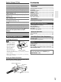
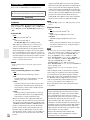
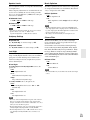
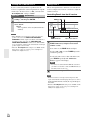
Installing the Batteries
Note
Others
• If the remote controller
doesn’t work reliably, try
replacing the batteries.
• Don’t mix new and old
batteries or different
types of batteries.
• If you intend not to use
Batteries (AA/R6)
the remote controller for
a long time, remove the batteries to prevent damage from leakage or corrosion.
• Remove expired batteries as soon as possible to prevent damage
from leakage or corrosion.
Troubleshooting ............................................................. 64
Specifications ................................................................. 69
About HDMI ..................................................................... 72
Using an RIHD-compatible TV, Player, or Recorder ... 73
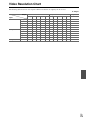
Video Resolution Chart.................................................. 75
To reset the AV receiver to its factory defaults, turn it
on and, while holding down VCR/DVR, press
ON/STANDBY (➔ 64).
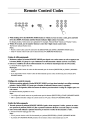
Aiming the Remote Controller
To use the remote controller, point it at the AV receiver’s
remote control sensor, as shown below.
Remote control sensor
AV receiver
Approx. 16 ft. (5 m)
En
5
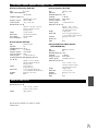
Features
AV Receiver HT-R680
• 130 Watts/Channel @ 6 ohms
• WRAT–Wide Range Amplifier Technology
(5 Hz to 100 kHz bandwidth)
• Optimum Gain Volume Circuitry
• H.C.P.S. (High Current Power Supply) Massive High
Power Transformer
• HDMI (Ver.1.4 with Audio Return Channel, 3D), DeepColor, x.v.Color*, Lip Sync, DTS*1-HD Master Audio,
DTS-HD High Resolution Audio, Dolby TrueHD*2,
Dolby Digital Plus, DSD and Multi-CH PCM
• Dolby Pro Logic IIz*2 (with “Front High” Direction
Mode)
• Non-Scaling Configuration
• A-Form Listening Mode Memory
• Direct Mode
• Music Optimizer*3 for Compressed Digital Music files
• 192 kHz/24-bit D/A Converters
• Powerful and Highly Accurate 32-bit Processing DSP
• Jitter Cleaning Circuit Technology
• 4 HDMI*4 Inputs and 1 Output
• Onkyo p for System Control
• 4 Digital Inputs (2 Optical/2 Coaxial)
• Component Video Switching (2 Inputs/1 Output)
• Front “Line in” Input for Portable audio player
• Universal Port for the Dock for iPod*/HD Radio™*5
tuner module
• Banana Plug-Compatible Speaker Posts
• Powered Zone 2
• 40 FM/AM Presets
• Audyssey 2EQ®*6 to Correct Room Acoustic Problems
• Audyssey Dynamic EQ®*6 for Loudness Correction
• Audyssey Dynamic Volume®*6 to Maintain Optimal
Listening Level and Dynamic Range
• Crossover Adjustment
(40/50/60/70/80/90/100/120/150/200 Hz)
• A/V Sync Control Function (up to 200 ms)
• On-Screen Display via HDMI
• Preprogrammed u-Compatible Remote
*1
Manufactured under license under U.S. Patent #’s: 5,451,942;
5,956,674; 5,974,380; 5,978,762; 6,226,616; 6,487,535;
7,212,872; 7,333,929; 7,392,195; 7,272,567 & other U.S. and
worldwide patents issued & pending. DTS and the Symbol are
registered trademarks, & DTS-HD, DTS-HD Master Audio,
and the DTS logos are trademarks of DTS, Inc. Product
includes software.
© DTS, Inc. All Rights Reserved.
*2
*3
*4
“HDMI, the HDMI Logo, and High-Definition Multimedia
Interface are trademarks or registered trademarks of HDMI
Licensing LLC in the United States and other countries.”
*5
HD Radio™ and the HD Radio Ready logo are proprietary
trademarks of iBiquity Digital Corporation.
To receive HD Radio broadcasts, you must install an Onkyo
UP-HT1 HD Radio tuner module (sold separately).
*6
Manufactured under license from Audyssey Laboratories™.
U.S. and foreign patents pending. Audyssey 2EQ®,
Audyssey Dynamic Volume® and Audyssey Dynamic EQ®
are registered trademarks and trademarks of
Audyssey Laboratories.
*
*
*
*
En
6
Manufactured under license from Dolby Laboratories.
“Dolby”, “Pro Logic” and the double-D symbol are trademarks of Dolby Laboratories.
Music Optimizer™ is a trademark of Onkyo Corporation.
iPod is a trademark of Apple Inc., registered in the U.S. and
other countries.
iPhone is a trademark of Apple Inc.
“Made for iPod” means that an electronic accessory has been
designed to connect specifically to iPod and has been certified
by the developer to meet Apple performance standards.
“Works with iPhone” means that an electronic accessory has
been designed to connect specifically to iPhone and has been
certified by the developer to meet Apple performance standards.
Apple is not responsible for the operation of this device or its
compliance with safety and regulatory standards.
“x.v.Color” is a trademark of Sony Corporation.
Speaker Package HTP-680
SKF-680 L/R 2-Way Front Speakers
• 4" (10 cm) Cone woofer
• 1" (2.5 cm) Balanced dome tweeter
• Max. input power: 130 W
• Gloss Finished
• 6-ohm impedance
• Color-coded speaker terminals and speaker cable
SKC-680 2-Way Center Speaker
• 4" (10 cm) Cone woofer
• 1" (2.5 cm) Balanced dome tweeter
• Max. input power: 130 W
• Gloss Finished
• 6-ohm impedance
• Color-coded speaker terminals and speaker cable
SKR-680 L/R Full-Range Surround Speakers
SKB-680 L/R Full-Range Surround Back Speakers
• 3-1/4" (8 cm) Full-Range Speaker
• Max. input power: 130 W
• Gloss Finished
• 6-ohm impedance
• Color-coded speaker terminals and speaker cable
SKW-770 Bass Reflex Powered Subwoofer
• 10" (25 cm) Cone
• Output Level Control
• Max. power: 290 W (Dynamic power)
Universal Port Option Dock for iPod®
(UP-A1)
• Easily links iPod/iPhone models with Onkyo A/V Systems.
Speaker Package HTP-780
SKF-780 L/R 2-Way Front Speakers
• 3-1/4" (8 cm) Cone woofer
• 1" (2.5 cm) Balanced dome tweeter
• Max. input power: 130 W
• 6-ohm impedance
• Color-coded speaker terminals and speaker cable
SKC-780 2-Way Center Speaker
• 3-1/4" (8 cm) Cone woofer
• 1" (2.5 cm) Balanced dome tweeter
• Max. input power: 130 W
• 6-ohm impedance
• Color-coded speaker terminals and speaker cable
SKR-780 L/R Full-Range Surround Speakers
SKB-780 L/R Full-Range Surround Back Speakers
• 3-1/4" (8 cm) Cone
• Max. input power: 130 W
• 6-ohm impedance
• Color-coded speaker terminals and speaker cable
SKW-780 Bass Reflex Powered Subwoofer
• 10" (25 cm) Cone
• Output Level Control
• Max. power: 290 W (Dynamic power)
En
7
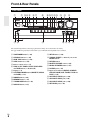
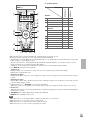
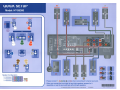
Front & Rear Panels
Front Panel
a
b cd e
fg
q r
h
i j klm
n
s
o
p
t u v
w
The actual front panel has various logos printed on it. They are not shown here for clarity.
The page numbers in parentheses show where you can find the main explanation for each item.
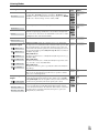
a ON/STANDBY button (➔ 24)
m SETUP button (➔ 38)
b STANDBY indicator (➔ 24)
c HDMI THRU indicator (➔ 49)
n TUNING, PRESET (➔ 30 to 31), arrow and
ENTER buttons
d ZONE 2 indicator (➔ 54)
o RETURN button
e Remote control sensor (➔ 5)
p MASTER VOLUME control (➔ 25)
f ZONE 2, OFF, ZONE 2 LEVEL/TONE LEVEL
and TONE buttons (➔ 50, 54 to 55)
q MUSIC OPTIMIZER button (➔ 51)
g Display (➔ 9)
En
8
r PHONES jack (➔ 27)
h LISTENING MODE buttons (MOVIE/TV, MUSIC
and GAME) (➔ 33)
s Input selector buttons (BD/DVD, VCR/DVR,
CBL/SAT, GAME, AUX, TUNER, TV/CD and
PORT) (➔ 25)
i DIMMER button (➔ 26)
t AUX INPUT LINE IN jack (➔ 20)
j MEMORY button (➔ 31)
u AUX INPUT VIDEO jack (➔ 20)
k TUNING MODE button (➔ 30)
v AUX INPUT AUDIO jacks (➔ 20)
l DISPLAY button (➔ 25)
w SETUP MIC jack (➔ 28)
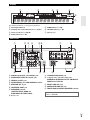
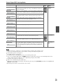
Display
a
b
c
d
e
f
g
For detailed information, see the pages in parentheses.
a Audio input indicators
e SLEEP indicator (➔ 26)
b Listening mode and format indicators (➔ 33, 51)
f MUTING indicator (➔ 26)
c Audyssey indicators (➔ 28, 44)
g Message area
d Tuning indicators (➔ 30)
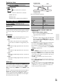
Rear Panel
a
b c d
ef
i
j
k
g
l
h
m
a DIGITAL IN OPTICAL and COAXIAL jacks
i u REMOTE CONTROL jack
b COMPONENT VIDEO IN and OUT jacks
j Composite video and analog audio jacks
(BD/DVD IN, VCR/DVR IN and OUT, CBL/SAT IN,
GAME IN and TV/CD IN)
c HDMI IN and OUT jacks
d FM ANTENNA jack and AM ANTENNA terminal
e MONITOR OUT V jack
k ZONE 2 LINE OUT jacks
f UNIVERSAL PORT jack
l SUBWOOFER PRE OUT jack
g SPEAKERS terminals
(CENTER, FRONT, SURR and
SURR BACK OR FRONT HIGH)
m FRONT HIGH OR ZONE 2 SPEAKERS terminals
h Power cord
See “Connecting the AV Receiver” for connection information (➔ 16 to 23).
En
9
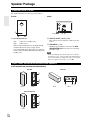
Speaker Package
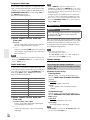
Subwoofer (SKW-770/780)
For detailed information, see the pages in parentheses.
■ Front
■ Rear
a
To AC outlet
a Standby/On indicator
Red:
Blue:
b c
b OUTPUT LEVEL control (➔ 25)
This control is used to adjust the volume of the subwoofer.
Subwoofer in standby mode
Subwoofer on
With the Auto Standby function, the SKW-770/780
automatically turns on when an input signal is
detected in Standby mode. When there’s no input signal for a while, the SKW-770/780 automatically enters
Standby mode.
c LINE INPUT (➔ 17)
This RCA input should be connected to the SUBWOOFER PRE OUT on the AV receiver with supplied RCA cable.
Note
• The Auto Standby function turns the subwoofer on when the
input signal exceeds a certain level. If the Auto Standby function
does not work reliably, try slightly increasing or decreasing the
subwoofer output level on the AV receiver (➔ 42).
Front, Center, Surround and Surround Back Speakers
■ HTP-680 (SKF-680, SKC-680, SKR-680, SKB-680)
SKF-680
SKC-680
a
b
a
Front
Front
Rear
SKR-680/SKB-680
a
b
a
Front
En
10
Rear
ba
a
Rear
■ HTP-780 (SKF-780, SKC-780, SKR-780, SKB-780)
SKF-780
SKC-780
a b
a
Rear
Front
b
SKR-780/SKB-780
a
b
Front
Front
Rear
Rear
a Keyhole slots
These keyhole slots can be used to wall-mount the
speaker. See “Wall Mounting” for mounting instructions (➔ 14).
b Speaker terminals
These push terminals are for connecting the speaker to
the HT-R680 with the supplied speaker cables.
The supplied speaker cables are color-coded for easy
identification. Simply connect each cable to the samecolored positive speaker terminal.
Caution
• The front grilles are not designed to be removed so do
not attempt to remove them forcibly, as this will damage
them.
En
11
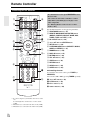
Remote Controller
Controlling the AV Receiver
a
h
b
*1
i
j
c
d
a
e
c
k *2
To control the AV receiver, press RECEIVER to select
Receiver mode.
You can also use the remote controller to control
Onkyo Blu-ray Disc/DVD player, CD player and
other components.
See “Entering Remote Control Codes” for more
details (➔ 61).
For detailed information, see the pages in parentheses.
a ON/STANDBY button (➔ 24)
b REMOTE MODE/INPUT SELECTOR buttons
(BD/DVD, VCR/DVR, CBL/SAT, GAME, AUX,
TUNER, TV/CD and PORT) (➔ 25)
c SP LAYOUT button (➔ 26)
d Arrow q/w/e/r and ENTER buttons
e SETUP button (➔ 38)
l
f LISTENING MODE buttons (MOVIE/TV, MUSIC,
GAME and STEREO) (➔ 33)
g DIMMER button (➔ 26)
m *3
h DISPLAY button (➔ 25)
i MUTING button (➔ 26)
j VOL q/w button (➔ 25)
k VIDEO button (➔ 26)
l RETURN button
f
m AUDIO button (➔ 26)
n SLEEP button (➔ 26)
g
b
d
■ Controlling the tuner
To control the AV receiver’s tuner, press TUNER (or
RECEIVER).
You can select AM or FM by pressing TUNER repeatedly.
n
a Arrow q/w buttons (➔ 30)
b D.TUN button (➔ 30)
c CH +/– button (➔ 31)
d Number buttons (➔ 30)
*1
*2
*3
En
12
To control component, you must first enter remote control
code.
See “Entering Remote Control Codes” for more details
(➔ 61).
This button acts as a shortcut for the Video menu (➔ 26).
This button acts as a shortcut for the Audio menu (➔ 26).
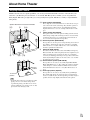
About Home Theater
Enjoying Home Theater
Thanks to the AV receiver’s superb capabilities, you can enjoy surround sound with a real sense of movement in your
own home—just like being in a movie theater or concert hall. With Blu-ray Discs or DVDs, you can enjoy DTS and
Dolby Digital. With analog or digital TV, you can enjoy Dolby Pro Logic IIx, DTS Neo:6, or Onkyo’s original DSP listening modes.
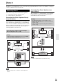
Speaker illustrations are based on HTP-680.
ab
f
c
ij
de gh
Corner
position
1/3 of wall
position
Tip
a b Front speakers (SKF-680/780)
These output the overall sound. Their role in a home theater is to provide a solid anchor for the sound image. They should be positioned
facing the listener at about ear level, and equidistant from the TV.
Angle them inward so as to create a triangle, with the listener at the
apex.
c Center speaker (SKC-680/780)
This speaker enhances the front speakers, making sound movements
distinct and providing a full sound image. In movies it’s used mainly
for dialog. Position it close to your TV facing forward at about ear
level, or at the same height as the front speakers.
d e Surround speakers (SKR-680/780)
These speakers are used for precise sound positioning and to add realistic ambience. Position them at the sides of the listener, or slightly
behind, about 2 to 3 feet (60 to 100 cm) above ear level. Ideally they
should be equidistant from the listener.
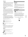
f Subwoofer (SKW-770/780)
The subwoofer handles the bass sounds of the LFE (Low-Frequency
Effects) channel. The volume and quality of the bass output from your
subwoofer will depend on its position, the shape of your listening
room, and your listening position. In general, a good bass sound can be
obtained by installing the subwoofer in a front corner, or at one-third
the width of the wall, as shown.
g h Surround back speakers (SKB-680/780)
These speakers are necessary to enjoy Dolby Digital EX, DTS-ES
Matrix, DTS-ES Discrete, etc. They enhance the realism of surround
sound and improve sound localization behind the listener. Position
them behind the listener about 2 to 3 feet (60 to 100 cm) above ear
level.
i j Front high speakers (Optional)
These speakers are necessary to enjoy Dolby Pro Logic IIz Height.
They significantly enhance the spatial experience. Position them at
least 3.3 feet (100 cm) above the front speakers (preferably as high as
possible) and at an angle slightly wider than the front speakers.
• To find the best position for your subwoofer, while
playing a movie or some music with good bass,
experiment by placing your subwoofer at various
positions within the room, and choose the one that
provides the most satisfying results.
En
13
Connections
Connecting the AV Receiver
Attaching the Speaker Bases
■ SKF-780
Before you connect the speakers, attach the supplied
speaker base to each SKF-780.
1. Turn the speaker upside down with the protection
cover attached.
2. Align the speaker base while the arrow mark
is
headed in the same direction as the speaker’s face.
Be careful not to tip over the speaker.
3. Align the screw holes on the speaker base with those
on the bottom of each speaker, and affix the speaker
base using the supplied screws. Recommended torque
is 10 kgf·cm (9 lbf·in).
Be careful not to tip over the speaker.
4. Turn the speaker right side up.
5. Remove the protection cover.
Top of SKF-780
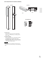
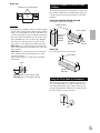
Wall Mounting
The speakers can easily be wall mounted by using the keyhole slots.
Front, Surround and Surround Back
Speakers
To mount the front, surround and surround back speakers
vertically, use the keyhole slot shown to hang each speaker
on a screw that’s securely screwed into the wall.
■ SKF-680, SKR-680, SKB-680
To prevent the speaker from vibrating against the wall,
attach two of the supplied rubber stoppers to the rear of
each speaker.
Protection cover
Keyhole slot for
wall mounting
Rubber stoppers
Supplied screws
Arrow mark
■ SKR-780,SKB-780
Speaker base
Keyhole slot for
wall mounting
Bottom of SKF-780
Center Speaker
To mount the center speaker horizontally, use the two keyhole slots shown to hang each speaker on two screws that
are securely screwed into the wall.
SAFETY PRECAUTIONS:
• Attach the speaker bases in a manner that will not
allow the speakers to tip over.
• Be sure to tighten the screws when you attach the
speaker bases.
• Attach the speaker bases on a flat, level, and stable
floor.
• After you attach the speaker bases, make sure that
the speakers stand upright and are stable.
En
14
■ SKC-680
To prevent the speaker from vibrating against the wall,
attach two of the supplied rubber stoppers to the rear of
each speaker.
Keyhole slot for wall mounting
Rubber
stoppers
8-1/4" (210 mm)
■ SKC-780
Keyhole slot for wall mounting
Using the Stoppers for a More Stable
Platform
We recommend using the provided stoppers to achieve the
best possible sound from your speakers. The stoppers prevent the speakers from moving, providing a more stable
platform.
7-7/8" (200 mm)
■ SKF-680, SKR-680, SKB-680, SKC-680
Use rubber stoppers for the speakers.
Rubber stoppers
Caution
• A mounting screw’s ability to support a speaker depends
on how well it’s anchored to the wall. If you have hollow
walls, screw each mounting screw into a stud. If there are
no studs, or the walls are solid, use suitable wall anchors.
• Use screws with a head diameter of 5/16" (8 mm) or less
and a shank diameter of 1/8" (4 mm) or less. With hollow walls, use a cable/pipe detector to check for any
power cables or water pipes before making any holes.
• (HTP-680) Leave a gap of between 5/32" (4 mm) and
5/16" (8 mm) between the wall and the base of the screw
head, as shown.
(HTP-780) Leave a gap of between 3/16" (5 mm) and
7/16" (10 mm) between the wall and the base of the
screw head, as shown.
(We recommend that you consult a home installation
professional.)
1-3/16" (30 mm)
Bottom of the
SKF-680/
SKR-680/
SKB-680
Bottom of the
SKC-680
1-9/16"
(40 mm)
■ SKC-780
Use cork stoppers for the center speaker.
Cork stoppers
Wall
Bottom of the
SKC-780
(HTP-680) 5/32" to 5/16"(4 mm to 8 mm)
(HTP-780) 3/16" to 7/16"(5 mm to 10 mm)
Using the Floor Pads for Subwoofer
If the subwoofer is placed on a hard floor (wood, vinyl,
tile, etc.) and playback is very loud, the subwoofer’s feet
may damage the flooring. To prevent this, place the supplied pads underneath the subwoofer’s feet. The pads also
provide a stable base for the subwoofer.
Pad
En
15
• Make sure the metal core of the wire does not have contact with the AV receiver’s rear panel. Doing so may
damage the AV receiver.
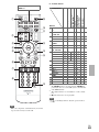
Connecting Your Speakers
Speaker Configuration
The following table indicates the channels you should use
depending on the number of speakers that you have.
For 7.1-channel surround-sound playback, you need
7 speakers and a powered subwoofer.
Number of speakers
2 3 4 5 6 7 7 8 9
Front speakers
✔ ✔ ✔ ✔ ✔ ✔ ✔ ✔ ✔
✔
Center speaker
Surround speakers
Surround back speaker*1*2
Surround back
✔ ✔ ✔ ✔ ✔ ✔
✔ ✔ ✔ ✔ ✔ ✔ ✔
✔
speakers*2
Front high speakers*2*3
*1
*2
*3
✔
✔
✔
✔ ✔ ✔
If you’re using only one surround back speaker, connect it to
the SURR BACK OR FRONT HIGH L terminals.
Front high and surround back speakers cannot be used at the
same time.
When you connect the front high left and right speakers, prepare for it separately, or use the surround back left and right
speakers.
No matter how many speakers you use, a powered subwoofer is recommended for a really powerful and solid
bass.
To get the best from your surround sound system, you
need to set the speaker settings. You can do this automatically (➔ 28) or manually (➔ 40).
Speaker Connection Precautions
Read the following before connecting your speakers:
• You can connect speakers with an impedance of between
6 and 16 ohms. If you use speakers with a lower impedance, and use the amplifier at high volume levels for a
long period of time, the built-in amp protection circuit
may be activated.
• Disconnect the power cord from the wall outlet before
making any connections.
• Pay close attention to speaker wiring polarity. In other
words, connect positive (+) terminals only to positive (+)
terminals, and negative (–) terminals only to negative (–)
terminals. If you get them the wrong way around, the
sound will be out of phase and will sound unnatural.
• Unnecessarily long, or very thin speaker cables may
affect the sound quality and should be avoided.
• Be careful not to short the positive and negative wires.
Doing so may damage the AV receiver.
En
16
• Don’t connect more than one cable to each speaker terminal. Doing so may damage the AV receiver.
• Don’t connect one speaker to several terminals.
Connecting the Speaker Cables
Screw-type speaker terminals
Strip 1/2" to 5/8" (12 to 15 mm) of
insulation from the ends of the
speaker cables, and twist the bare
wires tightly, as shown. (Supplied
speaker cables are already stripped.)
1/2" to 5/8"(12 to 15 mm)
Using Banana Plugs
• If you are using banana plugs, tighten the speaker terminal before inserting the banana plug.
• Do not insert the speaker code directly into the center hole of the speaker terminal.
Push-type speaker terminals
Strip 3/8" to 1/2" (10 to 12 mm) of insulation from the ends of
the speaker cables, and twist the bare wires tightly, as shown.
(Supplied speaker cables are already stripped.)
3/8" to 1/2"(10 to 12 mm)
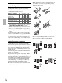
The following illustration shows which speaker should be connected to each pair of terminals. If you’re using only one
surround back speaker, connect it to the SURR BACK OR FRONT HIGH L terminals.
Speaker illustrations are based on HTP-680.
Surround
back right
speaker
Surround
back left
speaker
Surround
right
speaker
Surround
left
speaker
Front right
speaker
Front left
speaker
Center speaker
Tan
Front high
right
speaker
(Optional)
*
Front high
left
speaker
(Optional)
Brown
Gray
Blue
Red
White
Green
Powered
subwoofer
Using the supplied RCA cable, connect the subwoofer’s LINE INPUT jack to your AV receiver’s SUBWOOFER PRE OUT jack.
Note
• The front high speakers can also be connected to the SURR BACK OR FRONT HIGH SPEAKERS terminals. When doing so, set
“Surr Back/Front High” in Speaker Setup to “Front High” (➔ 40).
En
17
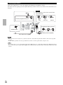
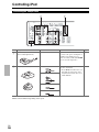
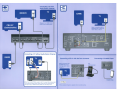
About AV Connections
Connected image with AV components
HDMI cable
Other cables
: Video & Audio
AV receiver
TV, projector, etc.
Blu-ray Disc/
DVD player
: Video
: Audio
AV receiver
Game console
TV, projector, etc.
Blu-ray Disc/
DVD player
• Before making any AV connections, read the manuals supplied with your AV components.
• Don’t connect the power cord until you’ve completed and double-checked all AV connections.
• Push plugs in all the way to make good connections (loose connections can cause noise or malfunctions).
• To prevent interference, keep audio and video cables away from power cords and speaker cables.
Cable
Video and
Audio
HDMI
Video
Component video
Jack
Y
Green
PB/CB
Blue
PR/CR
Red
V
Optical digital
audio
1/8" (3.5 mm)
Stereo mini plug
*
Yellow
OPTICAL
Coaxial digital
audio
Analog audio
(RCA)
Description
HDMI
Composite video
Audio
Right!
Wrong!
AV Cables and Jacks
Signal
Game console
HDMI connections can carry digital video and audio.
Component video separates the luminance (Y) and color
difference signals (PB/CB, PR/CR), providing the best picture quality (some TV manufacturers label their component video sockets slightly differently).
Composite video is commonly used on TVs, VCRs, and
other video equipment.
Optical digital connections allow you to enjoy digital
sound such as PCM*, Dolby Digital or DTS. The audio
quality is the same as coaxial.
Orange
Coaxial digital connections allow you to enjoy digital
sound such as PCM*, Dolby Digital or DTS. The audio
quality is the same as optical.
L
White
Analog audio connections (RCA) carry analog audio.
R
Red
This cable carries analog audio.
Available sampling rate for PCM input signal is 32/44.1/48/88.2/96 kHz. Even 176.4/192 kHz is effective in case of the HDMI connection.
Note
• The AV receiver does not support SCART plugs.
• The AV receiver’s optical digital jacks have shutter-type covers that open when an optical plug is inserted and close when it’s removed.
Push plugs in all the way.
Caution
• To prevent shutter damage, hold the optical plug straight when inserting and removing.
En
18
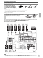
Connecting Your Components with HDMI
VCR or DVD recorder/Digital Video Recorder
Game console
TV, projector, etc.
Satellite, cable, set-top box, etc.
Blu-ray Disc/DVD player
Connect your components to the appropriate jacks. The default input assignments are shown below.
✔: Assignment can be changed (➔ 39).
Jack
Input
Output
Signal
Components
Assignable
Audio/Video
Blu-ray Disc/DVD player
✔
HDMI IN 2
VCR or DVD recorder/Digital Video Recorder
✔
HDMI IN 3
Satellite, cable, set-top box, etc.
✔
HDMI IN 4
Game console
✔
HDMI OUT
TV, projector, etc.
HDMI IN 1
Refer to “About HDMI” (➔ 72) and “Using an RIHD-compatible TV, Player, or Recorder” (➔ 73).
■ Audio return channel (ARC) function
Audio return channel (ARC) function enables an HDMI capable TV to send the audio stream to the HDMI OUT of the
AV receiver. To use this function, you must select the TV/CD input selector.
• To use ARC function, you must select the TV/CD input selector, your TV must support ARC function and “HDMI
Control (RIHD)” is set to “On”(➔ 49).
Tip
• To listen to audio received by the HDMI IN jacks through your TV’s speakers:
– Set the “TV Control” setting to “On” (➔ 50) for an p-compatible TV.
– Set the “Audio TV Out” setting to “On” (➔ 49) when the TV is not compatible with p or the “TV Control” setting to “Off”.
– Set your Blu-ray Disc/DVD player’s HDMI audio output setting to PCM.
– To listen to TV audio through the AV receiver, see “Connecting Your Components” (➔ 20).
Note
• When listening to an HDMI component through the AV receiver, set the HDMI component so that its video can be seen on the TV
screen (on the TV, select the input of the HDMI component connected to the AV receiver). If the TV power is off or the TV is set to
another input source, this may result in no sound from the AV receiver or the sound may be cut off.
• When the “Audio TV Out” setting is set to “On” (➔ 49) to hear from your TV’s speakers, by controlling the AV receiver’s volume,
the sound will be output from the AV receiver’s speakers, too. When the “TV Control” setting is set to “On” (➔ 50) to hear from
speakers of p-compatible TV, by controlling the AV receiver’s volume, the AV receiver’s speakers will produce sound while the
TV’s speakers are muted. To stop the AV receiver’s speakers producing sound, change the settings, change your TV’s settings, or turn
down the AV receiver’s volume.
En
19
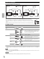
Connecting Your Components
The on-screen setup menus appear only on a TV that is connected to the HDMI OUT. If your TV is connected to
the MONITOR OUT V or the COMPONENT VIDEO OUT, use the AV receiver’s display when changing settings.
Front
Rear
A
C
B
D
E
Connect your components to the appropriate jacks. The default input assignments are shown below.
✔: Assignment can be changed (➔ 40).
No.
Jack
A
AUX INPUT
B
COMPONENT
VIDEO
Signal
Components
LINE IN
Analog audio
Portable audio player
VIDEO
Composite video
Camcorder, etc
AUDIO L/R
Analog audio
IN 1 (BD/DVD)
Component video
IN 2 (CBL/SAT)
OUT
C
DIGITAL IN
OPTICAL
COAXIAL
D
✔
Satellite, cable, set-top box, etc.
✔
TV, projector, etc.
Game console
✔
IN 2 (TV/CD)
TV, CD player
✔
IN 1 (BD/DVD)
Blu-ray Disc/DVD player
✔
IN 2 (CBL/SAT)
Satellite, cable, set-top box, etc.
✔
IN 1 (GAME)
Digital audio
Composite video
TV, projector, etc.
BD/DVD IN
Analog audio and
composite video
Blu-ray Disc/DVD player
CBL/SAT IN
VCR or DVD recorder/digital
video recorder
Satellite, cable, set-top box, etc.
GAME IN
E
Blu-ray Disc/DVD player
MONITOR OUT
VCR/DVR IN
Assignable
Game console
TV/CD IN
Analog audio
TV, CD player, Turntable*1,
cassette tape deck, MD, CD-R
UNIVERSAL PORT
Analog audio/
video
Universal port optional dock
(UP-A1 etc.)
Note
*1
•
•
•
•
•
En
20
Connect a turntable (MM) that has a phono preamp built-in. If your turntable (MM) doesn’t have it, you’ll need a commercially
available phono preamp.
If your turntable has a moving coil (MC) type cartridge, you’ll need a commercially available MC head amp or MC transformer as
well as a phono preamp. See your turntable’s manual for details.
When you connect to both AUX INPUT AUDIO jacks and AUX INPUT LINE IN jack at the same time, AUX INPUT LINE IN jack
will be given a higher priority.
The AV receiver can output audio and video signals from the AUX INPUT jacks to the VCR/DVR OUT jacks.
With connection D, you can listen and record audio from the external components while you are in Zone 2. You can listen and record
audio from the external components in the main room; you can listen to the audio in Zone 2 as well.
With connection C, you can enjoy Dolby Digital and DTS. (To record or listen in Zone 2 as well, use C and D.)
With connection D, if your Blu-ray Disc/DVD player has both the main stereo and multichannel outputs, be sure to connect the main
stereo.
■ How to record the video
With the connections described above, you cannot record the video through the AV receiver. To make a connection for
video recording (➔ 32).
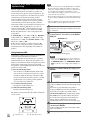
Connecting Onkyo u Components
Step 1:
Make sure that each Onkyo component is connected
with an analog audio cable (connection D in the hookup
examples) (➔ 20).
Step 2:
Make the u connection (see illustration below).
Step 3:
If you’re using an RI Dock, or cassette tape deck,
change the Input Display (➔ 27).
With u (Remote Interactive), you can use the following
special functions:
■ System On/Auto Power On
When you start playback on a component connected via
u while the AV receiver is on Standby, the AV
receiver will automatically turn on and select that component as the input source.
■ Direct Change
When playback is started on a component connected via
u, the AV receiver automatically selects that component as the input source.
■ Remote Control
You can use the AV receiver’s remote controller to control your other u-capable Onkyo components, pointing the remote controller at the AV receiver’s remote
control sensor instead of the component. You must enter
the appropriate remote control code first (➔ 61).
Note
• Use only u cables for u connections. u cables are supplied
with Onkyo players (DVD, CD, etc.).
• Some components have two u jacks. You can connect either
one to the AV receiver. The other jack is for connecting additional u-capable components.
• Connect only Onkyo components to u jacks. Connecting other
manufacturer’s components may cause a malfunction.
• Some components may not support all u functions. Refer to
the manuals supplied with your other Onkyo components.
• While Zone 2 is on, the System On/Auto Power On and Direct
Change u functions do not work.
• Do not use RI connections if you use HDMI Control (RIHD)
(➔ 49).
IN
L
R
TV/CD
IN
L
REMOTE
CONTROL
R
BD/DVD
e.g., CD player
e.g., DVD player
R
L
ANALOG
AUDIO OUT
R
L
ANALOG
AUDIO OUT
En
21
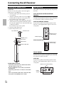
Connecting Antenna
This section explains how to connect the supplied indoor FM antenna and AM loop antenna.
The AV receiver won’t pick up any radio signals without any antenna connected, so you must connect the antenna to use
the tuner.
Caution
• Be careful that you don’t injure yourself when
using thumbtacks.
Insert the plug fully into the jack.
Push.
Insert wire.
Release.
Assembling the AM loop antenna.
Thumbtacks, etc.
AM loop antenna (supplied)
Indoor FM antenna (supplied)
Note
• Once your AV receiver is ready for use, you’ll need to tune into a radio station and position the antenna to achieve the best possible
reception.
• Keep the AM loop antenna as far away as possible from your AV receiver, TV, speaker cables, and power cords.
Tip
• If you cannot achieve good reception with the supplied indoor FM antenna, try a commercially available outdoor FM antenna instead.
• If you cannot achieve good reception with the supplied indoor AM loop antenna, try using it with a commercially available outdoor AM
antenna.
En
22
Which Connections Should I Use?
The AV receiver supports several connection formats for compatibility with a wide range of AV equipment. The format
you choose will depend on the formats supported by your components. Use the following sections as a guide.
The on-screen setup menus appear only on a TV that is connected to the HDMI OUT. If your TV is connected to
the MONITOR OUT V or the COMPONENT VIDEO OUT, use the AV receiver’s display when changing settings.
Video Connection Formats
Video component can be connected by using any one of the following video connection formats: composite video, component video, or HDMI, the latter offering the best picture quality.
Video input signals flow through the AV receiver as shown,
Video Signal Flow Chart
with composite video and component video sources all being
Blu-ray Disc/DVD player, etc.
upconverted for the HDMI output.
The composite video and component video outputs pass
Composite
Component
HDMI
through their respective input signals as they are.
IN
When you connect audio component to an HDMI or COMPONENT input, you must assign that input to an input selecAV receiver
tor (➔ 39).
MONITOR OUT
Composite
Component
HDMI
TV, projector, etc.
■ Signal Selection
If signals are present at more than one input, the inputs will
be selected automatically in the following order of priority:
HDMI, component video, composite video.
However, for component video only, regardless of whether a
component video signal is actually present, if a component
video input is assigned to the input selector, that component
video input will be selected. And if no component video
input is assigned to the input selector, this will be interpreted
as no component video signal being present.
In the Signal Selection Example shown on the right, video
signals are present at both the HDMI and composite video
inputs, however, the HDMI signal is automatically selected
as the source and video is output by the HDMI outputs.
Signal Selection Example
Blu-ray Disc/DVD player, etc.
Composite
Component
HDMI
IN
AV receiver
MONITOR OUT
Composite
Component
HDMI
TV, projector, etc.
Audio Connection Formats
Audio component can be connected by using any of the
following audio connection formats: analog, optical, coaxial, or HDMI.
When choosing a connection format, bear in mind that the
AV receiver does not convert digital input signals for analog line outputs and vice versa. For example, audio signals
connected to an optical or coaxial digital input are not output by the analog VCR/DVR OUT.
Audio Signal Flow Chart
Blu-ray Disc/DVD player, etc.
Analog
Optical
Coaxial
HDMI
IN
AV receiver
*1
*1
*1
OUT
Analog
If signals are present at more than one input, the inputs
will be selected automatically in the following order of priority: HDMI, digital, analog.
HDMI
*1 *2
TV, projector, etc.
*1
*2
Depends on the “Audio TV Out” setting (➔ 49).
This setting is available, when “Audio Return Channel”
setting is set to “Auto” (➔ 49), you must select the TV/CD
input selector and your TV must support ARC function.
En
23
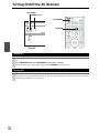
Turning On & Basic Operations
Turning On/Off the AV Receiver
ON/STANDBY
STANDBY indicator
ON/STANDBY
RECEIVER
Turning On
Press ON/STANDBY on the front panel.
or
Press RECEIVER followed by ON/STANDBY on the remote controller.
The AV receiver comes on, the display lights, and the STANDBY indicator goes off.
Turning Off
Press ON/STANDBY on the front panel or the remote controller.
The AV receiver will enter Standby mode. To prevent any loud surprises when you turn on the AV receiver, always
turn down the volume before you turn it off.
En
24
Basic Operations
The on-screen menus appear only on a TV that is connected to the HDMI OUT. If your TV is connected to
the MONITOR OUT V or the COMPONENT VIDEO
OUT, use the AV receiver’s display when changing
settings.
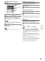
■ Adjusting the subwoofer volume level
Use the subwoofer’s OUTPUT LEVEL control to
adjust the volume of the subwoofer.
Because our ears are less sensitive to very low bass
sounds, there’s a temptation to set the level of the
subwoofer too high. As a rule of thumb, set the subwoofer level to what you think is the optimal level,
and then back it off slightly.
This manual describes the procedure using the
remote controller unless otherwise specified.
Selecting the Language Used for the
Onscreen Setup Menus
You can determine the language used for the onscreen
setup menus. See “Language” in the “OSD Setup”
(➔ 48).
Playing the Connected Component
■ Operating on the AV receiver
1
Use the input selector buttons to select the input
source.
2
Start playback on the source component.
See also:
• “Controlling Other Components” (➔ 60)
• “Controlling iPod” (➔ 56)
• “Listening to the Radio” (➔ 30)
3
To adjust the volume, use the MASTER VOLUME
control.
4
Select a listening mode and enjoy!
See also:
• “Using the Listening Modes” (➔ 33)
• “Audyssey” (➔ 44)
Note
• When the subwoofer volume level is set to a positive (+) value,
the maximum master volume level is reduced proportionally.
Displaying Source Information
You can display various information about the current
input source as follows. (Components connected to the
UNIVERSAL PORT jack are excluded.)
Press RECEIVER followed by DISPLAY repeatedly to cycle through the available information.
Tip
• Alternatively, you can use the AV receiver’s DISPLAY.
The following information can typically be displayed.
Input source &
volume*1
Signal format*2
or sampling
frequency
Input & output
resolution
■ Operating with the remote controller
1
Press RECEIVER followed by INPUT SELECTOR.
2
Start playback on the source component.
See also:
• “Controlling Other Components” (➔ 60)
• “Controlling iPod” (➔ 56)
• “Listening to the Radio” (➔ 30)
3
4
Input source &
listening mode*3
*1
*2
To adjust the volume, use VOL q/w.
Select a listening mode and enjoy!
See also:
• “Using the Listening Modes” (➔ 33)
• “Audyssey” (➔ 44)
*3
When AM or FM radio is used, the band, preset number, and
frequency are displayed.
If the input signal is analog, no format information is displayed. If the input signal is PCM, the sampling frequency is
displayed. If the input signal is digital but not PCM, the signal
format is displayed.
Information is displayed for about three seconds, then the previously displayed information reappears.
The input source is displayed with the default name even
when you have entered a custom name in “Name Edit”
(➔ 45).
En
25
Using the Music Optimizer
The Music Optimizer function enhances the sound quality
of compressed music files.
Selecting Speaker Layout
You can prioritize which speakers you want to use.
Press RECEIVER followed by SP LAYOUT
repeatedly.
`Speaker Layout:FH:
The sound from front high speakers is output
by priority.
`Speaker Layout:SB:
The sound from surround back speakers is output by priority.
Press MUSIC OPTIMIZER on the front panel.
The M.Opt indicator lights on the display.
Tip
• Alternatively, you can use the remote controller’s AUDIO and
arrow buttons.
• See “Music Optimizer” for more details (➔ 51).
Setting the Display Brightness
You can adjust the brightness of the AV receiver’s display.
Press RECEIVER followed by DIMMER repeatedly to select: dim, dimmer, or normal brightness.
Note
• If the Powered Zone 2 is being used (➔ 54), this setting cannot
be selected.
• When the listening mode that doesn’t support front high or surround back speakers is used, the setting cannot be selected.
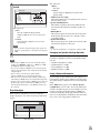
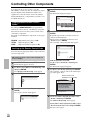
Using the Audio and Video Menus
Tip
• Alternatively, you can use the AV receiver’s DIMMER.
Muting the AV Receiver
You can temporarily mute the output of the AV receiver.
Press RECEIVER followed by MUTING.
The output is muted and the MUTING indicator
flashes on the display.
Tip
• To unmute, press MUTING again or adjust the volume.
• The Mute function is cancelled when the AV receiver is set to
Standby.
By pressing AUDIO or VIDEO, you can have a quick
access to frequently used menus without having to go
through the long standard menu. The menus enable you to
change settings and view the current information.
1
Press RECEIVER followed by AUDIO or VIDEO.
Either of the following screens will be superimposed
on the TV screen.
BD/DVD
Audio
Video
Info
Input Sel
Listening Mode
Bass
Treble
Subwoofer Level
Center Level
Dynamic EQ
Dynamic Volume
0dB
BD/DVD
Using the Sleep Timer
With the sleep timer, you can set the AV receiver to turn
off automatically after a specified period.
Press RECEIVER followed by SLEEP repeatedly
to select the required sleep time.
The sleep time can be set from 90 to 10 minutes in
10 minute steps.
The SLEEP indicator lights on the display when the
sleep timer has been set. The specified sleep time
appears on the display for about 5 seconds, then the
previous display reappears.
Tip
• If you need to cancel the sleep timer, press SLEEP repeatedly
until the SLEEP indicator goes off.
• To check the time remaining until the AV receiver sleeps, press
SLEEP. Note that if you press SLEEP while the sleep time is
being displayed, you’ll shorten the sleep time by 10 minutes.
En
26
Audio
Video
Info
Input Sel
Listening Mode
Wide Mode
Picture Mode
Auto
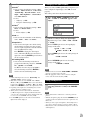
2
Use q/w/e/r to make the desired selection.
■ Audio*1
` You can change the following settings: “Bass”,
“Treble”, “Subwoofer Level”, “Center Level”,
“Dynamic EQ”, “Dynamic Volume”, “Late
Night”, “Music Optimizer”, “Cinema filter”
and “Audio Selector”.
See also:
• “Audyssey” (➔ 44)
• “Using the Audio Settings” (➔ 50)
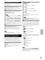
Changing the Input Display
When you connect an u-capable Onkyo component, you
must configure the input display so that u can work
properly.
This setting can be done only from the front panel.
1
Press TV/CD, GAME or VCR/DVR so that “TV/
CD”, “GAME” or “VCR/DVR” appears on the
display.
2
Press and hold down TV/CD, GAME or VCR/DVR
(about 3 seconds) to change the input display.
Repeat this step to select “MD”, “CDR”, “DOCK”
or “TAPE”.
For the TV/CD input selector, the input display
changes in this order:
TV/CD oMD oCDR
TAPE
DOCK
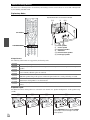
■ Listening Mode
` You can select the listening modes that are
grouped in the following categories: “MOVIE/
TV”, “MUSIC” and “GAME”.
Use q/w to select the category and e/r to
select the listening mode. Press ENTER to
switch to the selected listening mode.
Note
*1
*2
*3
*4
*5
If Direct listening mode is selected, “Dynamic EQ” and
“Dynamic Volume” cannot be selected.
Only when you have selected “Custom” in the “Picture
Mode” (➔ 46), pressing ENTER allows you to adjust the following items; “Brightness”, “Contrast”, “Hue”, and “Saturation”. Press RETURN to return to the original Video menu.
Depending on the input source and listening mode, not all
channels shown here output the sound.
When you have entered a custom name in “Name Edit”
(➔ 45), the input source is displayed with that name. But
even if not, the component name may be displayed if the AV
receiver receives it via HDMI connection (➔ 19).
For the PORT input selector, the name of Universal Port
Option Dock will be displayed.
o
■ Input Sel*4*5
` You can select the input source while viewing
the information as follows: the name of input
selectors, input assignments, and radio information, and ARC function setting.
Press ENTER to display the current input
source, followed by q/w to select the desired
input source. Pressing ENTER again switches to
the selected input source.
o
■ Info*3*4
` You can view the information of the following
items: “Audio”, “Video” and “Tuner”.
o
■ Video*2
` You can change the following settings: “Wide
Mode” and “Picture Mode”.
See also:
• “Picture Adjust” (➔ 46)
For the GAME input selector, the setting changes in
this order:
GAME l DOCK
For the VCR/DVR input selector, the setting
changes in this order:
VCR/DVR l DOCK
Note
• DOCK can be selected for the TV/CD, GAME or VCR/DVR
input selector, but not at the same time.
• Enter the appropriate remote control code before using the
remote controller for the first time (➔ 60).
Using Headphones
Connect a pair of stereo headphones with a standard plug (1/4 inch or 6.3 mm) to the PHONES
jack.
Note
• Always turn down the volume before connecting your headphones.
• While the headphones plug is inserted in the PHONES jack, the
speakers are turned off. (The Powered Zone 2 speakers are not
turned off.)
• When you connect a pair of headphones, the listening mode is
set to Stereo, unless it’s already set to Stereo, Mono or Direct.
• Only the Stereo, Direct and Mono listening modes can be used
with headphones.
En
27
Audyssey 2EQ® Room Correction and
Speaker Setup
With the supplied calibrated microphone, Audyssey 2EQ
automatically determines the number of speakers connected, their size for purposes of bass management, optimum crossover frequencies to the subwoofer (if present),
and distances from the primary listening position.
Audyssey 2EQ then removes the distortion caused by
room acoustics by capturing room acoustical problems
over the listening area in both the frequency and time
domain. The result is clear, well-balanced sound for everyone. Enabling Audyssey 2EQ allows you to also use
Audyssey Dynamic EQ®, which maintains the proper
octave-to-octave balance at any volume level (➔ 44).
Before using this function, connect and position all of
your speakers.
If “Dynamic EQ” is set to “On” (➔ 44), the “Equalizer”
setting will be set to “Audyssey” (➔ 42). On the other
hand, if it is set to “Off”, the “Dynamic Volume” setting
will be set to “Off” (➔ 44).
It takes about 15 minutes to complete Audyssey 2EQ
Room Correction and Speaker Setup for 3 positions. Total
measurement time varies depending on the number of
speakers.
Note
• Make the room as quiet as possible. Background noise and Radio
Frequency Interference (RFI) can disrupt the room measurements. Close windows, televisions, radios, air conditioners, fluorescent lights, home appliances, light dimmers, or other
devices. Turn off the cell phone (even if it is not in use) or place
it away from all audio electronics.
• The microphone picks up test tones which played through each
speaker as Audyssey 2EQ Room Correction and Speaker Setup
run.
• Audyssey 2EQ Room Correction and Speaker Setup cannot be
performed while a pair of headphones is connected.
1
Turn on the AV receiver and the connected TV.
On the TV, select the input to which the AV receiver
is connected.
2
Set the speaker setup microphone at the Main Listening Position a, and connect it to the SETUP
MIC jack.
SETUP MIC jack
Speaker setup
microphone
Using Audyssey 2EQ
The speaker setting menu appears.
Using Audyssey 2EQ to create a listening environment in
your home theater that all listeners will enjoy,
Audyssey 2EQ takes measurements at up to 3 positions
within the listening area. Position the microphone at ear
height of a seated listener with the microphone tip pointed
directly at the ceiling using a tripod. Do not hold the
microphone in your hand during measurements as this will
produce inaccurate results.
a First measurement position
Also referred to as the Main Listening Position this
refers to the most central position where one would
normally sit within the listening environment. 2EQ
uses the measurements from this position to calculate
speaker distance, level, polarity, and the optimum
crossover value for the subwoofer.
b Second measurement position
The right side of the listening area.
Note
• The on-screen setup menus appear only on a TV that is
connected to the HDMI OUT. If your TV is connected to
the MONITOR OUT V or the COMPONENT VIDEO
OUT, use the AV receiver’s display when changing settings.
3
2EQ: Auto Setup
Speaker Terminal Assign
Front High/Zone2
SurrBack/Front High
Press ENTER.
Audyssey 2EQ Room Correction and Speaker Setup
starts.
Test tones are played through each speaker as
Audyssey 2EQ Room Correction and Speaker Setup
runs. This process takes a few minutes. Please
refrain from talking during measurements and do
not stand between speakers and the microphone.
Do not disconnect the speaker setup microphone
during Audyssey 2EQ Room Correction and
Speaker Setup, unless you want to cancel the setup.
5
Place the setup microphone at the next position,
and then press ENTER.
Audyssey 2EQ performs more measurements. This
takes a few minutes.
6
When prompted, repeat step 5.
The distances from position a to b and a to c must be
at least 1 meter.
TV
c ab
28
: Listening area
a to c: Listening position
Front High
Surr Back
4
c Third measurement position
The left side of the listening area.
En
When you’ve finished making the settings, press
ENTER.
7
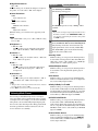
Use q/w to select an option, and then press
ENTER.
2EQ: Auto Setup
- - Review Speaker Configuration - Subwoofer
Front
Center
Surround
Front High
Surr Back
Surr Back Ch
Yes
40Hz
40Hz
100Hz
100Hz
120Hz
2ch
TV
Save
Cancel
The options are:
` Save:
Save the calculated settings and exit
Audyssey 2EQ® Room Correction and Speaker
Setup.
` Cancel:
Cancel Audyssey 2EQ Room Correction and
Speaker Setup.
Note
• You can view the calculated settings for the speaker configuration, speaker distances, and speaker levels by using
e/r.
8
Disconnect the speaker setup microphone.
Note
• When Audyssey 2EQ Room Correction and Speaker Setup is
complete, the “Equalizer” will be set to “Audyssey” (➔ 42).
The Audyssey indicator will light (➔ 9).
• You can cancel Audyssey 2EQ Room Correction and Speaker
Setup at any point in this procedure simply by disconnecting the
setup microphone.
• Do not connect or disconnect any speakers during
Audyssey 2EQ Room Correction and Speaker Setup.
• If the AV receiver is muted, it will be unmuted automatically
when Audyssey 2EQ Room Correction and Speaker Setup starts.
• Changes to the room after Audyssey 2EQ Room Correction and
Speaker Setup requires you run Audyssey 2EQ Room Correction and Speaker Setup again, as room EQ characteristics may
have changed.
Error Messages
While Audyssey 2EQ Room Correction and Speaker
Setup is in progress, one of the error messages below may
appear.
The options are:
` Retry:
Try again.
` Cancel:
Cancel Audyssey 2EQ Room Correction and
Speaker Setup.
• Ambient noise is too high.
The background noise is too loud. Remove the source of
the noise and try again.
• Speaker Matching Error!
The number of speakers detected was different from
that of the first measurement. Check the speaker connection.
• Writing Error!
This message appears if saving fails. Try saving again.
If this message appears after 2 or 3 attempts, contact
your Onkyo dealer.
• Speaker Detect Error
This message appears if a speaker is not detected. “No”
means that no speaker was detected.
Tip
• See “Speaker Configuration” for appropriate settings (➔ 16).
Changing the Speaker Settings Manually
You can manually make changes to the settings found during Audyssey 2EQ Room Correction and Speaker Setup.
See also:
• “Speaker Configuration” (➔ 41)
• “Speaker Distance” (➔ 41)
• “Level Calibration” (➔ 42)
• “Equalizer Settings” (➔ 42)
Using a Powered Subwoofer
If you’re using a powered subwoofer and it outputs very
low-frequency sound at a low volume level, it may not be
detected by Audyssey 2EQ Room Correction and Speaker
Setup.
If the “Subwoofer” appears on the “Review Speaker
Configuration” screen as “No”, increase the subwoofer’s
volume to the half-way point, set it to its highest crossover
frequency, and then try running Audyssey 2EQ Room
Correction and Speaker Setup again. Note that if the volume is set too high and the sound distorts, detection issues
may occur, so use an appropriate volume level.
2EQ: Auto Setup
Ambient noise is too high.
Retry
Cancel
Error message
En
29
Listening to the Radio
This section describes the procedure using the buttons on the front panel unless otherwise specified.
Using the Tuner
With the built-in tuner you can enjoy AM and FM radio
stations. You can store your favorite stations as presets for
quick selection.
This model changes FM/AM frequency in 200/10kHz (or
50/9kHz) steps.
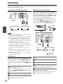
■ Manual tuning mode
1
2
Press TUNING MODE so that the AUTO indicator
goes off on the display.
Press and hold TUNING q/w.
The frequency stops changing when you release the
button.
Press the buttons repeatedly to change the frequency
one step at a time.
In manual tuning mode, FM stations will be in mono.
Listening to the Radio
Press TUNER to select either “AM” or “FM”.
In this example, FM has been selected.
Each time you press TUNER, the radio band
changes between AM and FM.
Band
Frequency
Tuning into weak FM stereo stations
If the signal from a stereo FM station is weak, it may be
impossible to get good reception. In this case, switch to
manual tuning mode and listen to the station in mono.
■ Tuning into stations by frequency
You can tune into AM and FM stations directly by entering the appropriate frequency.
1
On the remote controller, press TUNER repeatedly to select “AM” or “FM”, followed by D.TUN.
(Actual display depends on the country.)
Tuning into Radio Stations
(Actual display depends on the country.)
■ Auto tuning mode
1
2
Press TUNING MODE so that the AUTO indicator
lights on the display.
Press TUNING q/w.
Searching stops when a station is found.
When tuned into a station, the TUNED indicator lights.
When tuned into a stereo FM station, the FM STEREO
indicator lights on the display, as shown.
FM STEREO
AUTO
TUNED
En
30
2
Within 8 seconds, use the number buttons to enter
the frequency of the radio station.
For example, to tune to 87.50 (FM), press 8, 7, 5, 0.
If you have entered the wrong number, you can retry
after 8 seconds.
Presetting FM/AM Stations
You can store a combination of up to 40 of your favorite
FM/AM radio stations as presets.
1
Tune into the FM/AM station that you want to
store as a preset.
See the previous section.
2
Press MEMORY.
The preset number flashes.
3
While the preset number is flashing (about 8 seconds), use PRESET e/r to select a preset from 1
through 40.
4
Press MEMORY again to store the station or channel.
The station or channel is stored and the preset number stops flashing.
Repeat this procedure for all of your favorite FM/
AM radio stations.
Note
• You can name your radio presets for easy identification (➔ 45).
Its name is displayed instead of the band and frequency.
Selecting Presets
To select a preset, use PRESET e/r on the AV
receiver, or the remote controller’s CH +/–.
Tip
• You can also use the remote controller’s number buttons to select
a preset directly.
Deleting Presets
1
Select the preset that you want to delete.
See the previous section.
2
While holding down MEMORY, press TUNING
MODE.
The preset is deleted and its number disappears from
the display.
En
31
Recording
This section explains how to record the selected input source to a component with recording capability, and how to record
audio and video from different sources.
Connecting a Recording Component
L
Here you can record audio and video from completely
separate sources, allowing you to overdub audio onto your
video recordings. This function takes advantage of the fact
that when an audio-only input source (TV/CD) is selected,
the video input source remains unchanged.
In the following example, audio from the CD player connected to the TV/CD IN and video from the camcorder
connected to the AUX INPUT VIDEO jack are recorded
by the VCR connected to the VCR/DVR OUT jacks.
R
AUDIO
IN
Recording Separate AV Sources
VIDEO
IN
Camcorder
VCR,
DVD recorder
Cassette, CDR,
MD, etc.
Note
• The AV receiver must be turned on for recording. Recording is
not possible while it’s in Standby mode.
• If you want to record directly from your TV or playback VCR to
the recording VCR without going through the AV receiver, connect the TV/VCR’s audio and video outputs directly to the
recording VCR’s audio and video inputs. See the manuals supplied with your TV and VCR for details.
• Video signals connected to composite video inputs can be
recorded only via composite video outputs. If your TV/VCR is
connected to a composite video input, the recording VCR must
be connected to a composite video output.
• The surround sound and DSP listening modes cannot be
recorded.
• Copy-protected Blu-ray Disc/DVDs cannot be recorded.
• Sources connected to a digital input cannot be recorded. Only
analog inputs can be recorded.
• DTS signals will be recorded as noise, so don’t attempt analog
recording of DTS CDs or LDs.
AV Recording
Audio sources can be recorded to a recorder (e.g., cassette
deck, CDR, MD) connected to the VCR/DVR OUT jacks.
Video sources can be recorded to a video recorder (e.g.,
VCR, DVD recorder) connected to the VCR/DVR OUT
jack.
1
2
3
En
32
Use the input selector buttons to select the source
that you want to record.
You can watch the source while recording. The AV
receiver’s MASTER VOLUME control has no effect
on recording.
On your recorder, start recording.
On the source component, start playback.
If you select another input source during recording,
that input source will be recorded.
CD player
VCR
: Video signal
: Audio signal
1
Prepare the camcorder and CD player for playback.
2
3
4
Prepare the VCR for recording.
5
Start recording on the VCR and start playback on
the camcorder and CD player.
The video from the camcorder and the audio from
the CD player are recorded by the VCR.
Press AUX input selector.
Press TV/CD input selector.
This selects the CD player as the audio source, but
leaves the camcorder as the video source.
Using the Listening Modes
Selecting Listening Modes
See “About Listening Modes” for detailed information about the listening modes (➔ 34).
Listening Mode Buttons
Press RECEIVER first.
MOVIE/TV, MUSIC, GAME
MUSIC
MOVIE/TV
GAME
STEREO
MOVIE/TV button
This button selects the listening modes intended for use
with movies and TV.
MUSIC button
This button selects the listening modes intended for use
with music.
GAME button
This button selects the listening modes intended for use
with video games.
STEREO button
This button selects Stereo and All Channel Stereo listening modes.
• The Dolby Digital and DTS listening modes can only be selected if your Blu-ray Disc/DVD player is connected to the AV
receiver with a digital audio connection (coaxial, optical, or HDMI).
• The listening modes you can select depends on the format of the input signal. To check the format, see “Displaying Source
Information” (➔ 25).
• While a pair of headphones is connected, you can select the following listening modes: Mono, Direct, and Stereo.
• The listening modes cannot be used while you are listening to sound through your TV speakers coming from components
connected to the AV receiver (“TV Sp On” appears on the front panel).
En
33
About Listening Modes
The AV receiver’s listening modes can transform your listening room into a movie theater or concert hall, with high fidelity and stunning surround sound.
Explanatory Notes
Speaker illustrations are based on HTP-680.
ab
c
ij
SP LAYOUT
f
LISTENING MODE
de gh
a b Front speakers
c Center speaker
d e Surround speakers
f Subwoofer
g h Surround back speakers
i j Front high speakers
■ Input Source
The following audio formats are supported by the listening mode.
A
This is mono (monophonic) sound.
S
This is stereo (stereophonic) sound. Two independent audio signal channels are reproduced through two
speakers.
This is 5.1-channel surround sound. This surround system has five main channels of sound and a sixth subwoofer channel (called the point-one channel).
This is 7.1-channel surround sound. This is a further sound enhancement to 5.1 channel sound with two
additional speakers that provide greater sound envelopment and more accurate positioning of sounds.
This is DTS-ES surround sound. This surround system can produce a discrete or a matrix-encoded sixth
channel from existing DTS 5.1 encoded material.
This is Dolby Digital EX surround sound. This provides a center back surround channel from 5.1-channel
sources.
D
F
G
H
■ Speaker Layout
The illustration shows which speakers are activated in each channel. See “Speaker Configuration” for the speaker setup
(➔ 41).
Z
X
C
N
Press RECEIVER followed by SP LAYOUT
repeatedly to select front high or surround
back speakers.
En
34
Listening Modes
Listening Mode
Description
Input
Source
Direct
Speaker
Layout
In this mode, audio from the input source is output without surround-sound A
processing. The “Sp Config” (presence of speakers), “Sp Distance” and
S
D i r e c t d i o P P “A/V Sync” settings are enabled, but much of the processing set via AUDIO
D
is disabled. See “Advanced Setup” for more details (➔ 38).
F
G
H
ZXC
N*1
Stereo
Sound is output by the front left and right speakers and subwoofer.
A
S
S t e r e o d i oPP
D
Mono
Use this mode when watching an old movie with a mono soundtrack, or use F
it with the foreign language soundtracks recorded in the left and right chanM o n o e o d i o P P nels of some movies. It can also be used with DVDs or other sources contain- G
H
ing multiplexed audio, such as karaoke DVDs.
ZXC
N
Multichannel
This mode is for use with PCM multichannel sources.
D
XCN
Dolby Pro Logic IIx*2 Dolby Pro Logic IIx expands any 2-channel source for 7.1-channel playS
back. It provides a very natural and seamless surround-sound experience that
Dolby Pro Logic II
fully envelops the listener. As well as music and movies, video games can
P L b M o v i e P P also benefit from the dramatic spatial effects and vivid imaging. If you’re not
using any surround back speakers, Dolby Pro Logic II will be used instead
P L b M u s i c P P of Dolby Pro Logic IIx.
• Dolby PLIIx Movie
Use this mode with any stereo or Dolby Surround (Pro Logic) movie (e.g.,
P L bGame c PP
TV, DVD, VHS).
•
Dolby PLIIx Music
P L x GM o v i e P
Use this mode with any stereo or Dolby Surround (Pro Logic) music source
(e.g., CD, radio, cassette, TV, VHS, DVD).
P L x GM u s i c P
• Dolby PLIIx Game
Use this mode with video games, especially those that bear the Dolby Pro
P L x GG a m e c P
Logic II logo.
XCN
Mu l t i c h i o PP
• Dolby PLIIx Movie and Dolby PLIIx Music
These modes use the Dolby Pro Logic IIx modes to expand 5.1-channel
sources for 7.1-channel playback.
Dolby Pro Logic IIz
Height
D
N
Dolby Pro Logic IIz Height is designed to more effectively use existing
S
program material when height channel speaker outputs are present. Dolby
D
Pro Logic IIz Height can be used to upmix a variety of sources from movies F
and music, but are particularly well-suited to upmix game content.
N*3
These modes expand 5.1-channel sources for 6.1/7.1-channel playback.
D
They’re especially suited to Dolby EX soundtracks that include a matrixH
D o l b y c E X o P P encoded surround back channel. The additional channel adds an extra dimension and provides an enveloping surround sound experience, perfect for
D o l b y c D i E X P rotating and fly-by sound effects.
N*4
PL
z GH e i g h t
Dolby EX
En
35
Listening Mode
Description
Input
Source
Dolby Digital
In this mode, audio from the input source is output without surround-sound D
processing. “Sp Config” (presence of speakers), “Crossover”, “Sp DisD o l b y c D i o P P tance”, “A/V Sync” and much of the processing set via AUDIO are enabled.
Dolby Digital Plus*5 See “Advanced Setup” for more details (➔ 38).
D
Speaker
Layout
XCN
XCN
Do l b y cD+ oPP
F
XCN*1
Dolby TrueHD
D
XCN
F
XCN*1
D
XCN
D
XCN
F
XCN*1
D
XCN
F
XCN*1
S
D
XCN
D
XCN
D
XCN
D D Tl r u e H D
PP
DTS
DTS
d i oPP
DTS-HD High
Resolution Audio
D T S – HD
HR
DTS-HD Master
Audio
D T S – HD MS T R
DTS Express
DTS
Exp r ess
DSD*6
DSD
DTS 96/24*7
This mode is for use with DTS 96/24 sources. This is high-resolution DTS
with a 96 kHz sampling rate and 24-bit resolution, providing superior fidelD T S e 9 6 / 2 4 P P ity. Use it with DVDs that bear the DTS 96/24 logo.
DTS-ES Discrete*8
This mode is for use with DTS-ES Discrete soundtracks, which use a disG
crete surround back channel for true 6.1/7.1-channel playback. The seven
E S S D i s c r e t e totally separate audio channels provide better spatial imaging and 360degree sound localization, perfect for sounds that pan across the surround
channels. Use it with DVDs that bear the DTS-ES logo, especially those with
a DTS-ES Discrete soundtrack.
N* 4
DTS-ES Matrix*8
This mode is for use with DTS-ES Matrix soundtracks, which use a matrix- G
encoded back-channel for 6.1/7.1-channel playback. Use it with DVDs that
E S S M a t r i x t e bear the DTS-ES logo, especially those with a DTS-ES Matrix soundtrack.
N* 4
DTS Neo:6
XCN*4
This mode expands any 2-channel source for up to 7.1-channel playback. It S
uses seven full-bandwidth channels of matrix decoding for matrix-encoded
N e o : 6 t r i x t e material, providing a very natural and seamless surround sound experience
that fully envelops the listener.
Ne o : 6C
t ri ni e
xm
t e
a • Neo:6 Cinema
Use this mode with any stereo movie (e.g., TV, DVD, VHS).
N e o : 6 t M u s i c • Neo:6 Music
Use this mode with any stereo music source (e.g., CD, radio, cassette, TV,
VHS, DVD).
This mode uses Neo:6 to expand 5.1-channel sources for 6.1/7.1-channel
playback.
En
36
D
N* 4
Onkyo-Original DSP Listening Modes
Listening Mode
Description
Orchestra
Suitable for classical or operatic music, this mode emphasizes the surround A
channels in order to widen the stereo image, and simulates the natural rever- S
beration of a large hall.
D
Suitable for acoustic instruments, vocals, and jazz, this mode emphasizes the G
front stereo image, giving the impression of being right in front of the stage. H
Or ches t r a
Unplugged
Un p l u g g e d
Studio-Mix
S t u d i o –M i x
TV Logic
TV
Log i c
Game-RPG
Input
Source
Speaker
Layout
CN*9
Suitable for rock or pop music, listening to music in this mode creates a
lively sound field with a powerful acoustic image, like being at a club or rock
concert.
This mode adds realistic acoustics to TV shows produced in a TV studio,
surround effects to the entire sound, and clarity to voices.
Use this mode when playing role playing game discs.
G ame – RPG
Game-Action
Use this mode when playing action game discs.
Game – A c t i o n
Game-Rock
Use this mode when playing rock game discs.
Game –Ro c k
Game-Sports
Use this mode when playing sports game discs.
Game – S p o r t s
All Ch Stereo
A l l
Ch
S t
Full Mono
Fu l l
Mo n o
T-D (TheaterDimensional)
T–D
Ideal for background music, this mode fills the entire listening area with ste- A
reo sound from the front, surround, and surround back speakers.
S
D
In this mode, all speakers output the same sound in mono, so the sound you F
hear is the same regardless of where you are within the listening room.
G
H
With this mode you can enjoy a virtual surround sound even with only two or
three speakers. This works by controlling how sounds reach the listener’s left
and right ears. Good results may not be possible if there’s too much reverb,
so we recommend that you use this mode in an environment with little or no
natural reverb.
XCN*9
ZXC
N
Note
*1
When the input source contains the encoded front high channel, front high speakers output the sound.
If there are no surround back speakers, or Powered Zone 2 is being used, Dolby Pro Logic II is used.
*3 Surround back speakers are not supported.
*4 Front high speakers are not supported.
*5 For the Blu-ray Discs, Dolby Digital is used in a 3.1/5.1-channel speaker system.
*6 AV receiver can input the DSD signal from HDMI IN. Setting the output setting on the player side to PCM might obtain a better
sound according to the player. In that case, set the output setting on the player side to PCM.
*7 Depending on the input source, DTS is used.
*8 If there are no surround back speakers, DTS is used.
*9 Output can be switched between front high or surround back speakers by pressing SP LAYOUT [depending on the “Speaker Configuration” setting (➔ 41)].
• The listening modes cannot be selected with some source formats.
*2
En
37
Advanced Operations
Advanced Setup
On-screen Setup Menus
Common Procedures in Setup Menu
The on-screen setup menus appear only on a TV that
is connected to the HDMI OUT. If your TV is connected to the composite video MONITOR OUT or the
COMPONENT VIDEO OUT, use the AV receiver’s
display when changing settings.
This manual describes the procedure using the
remote controller unless otherwise specified.
Remote indicator
RECEIVER
ENTER
q/w/e/r
a
b
c
d
e
f
g
h
i
1.
2.
3.
4.
5.
6.
7.
8.
9.
Input/Output Assign
Speaker Setup
Audio Adjust
Source Setup
Listening Mode Preset
Miscellaneous
Hardware Setup
Remote Controller Setup
Lock Setup
a Input/Output Assign
(➔ 39)
1. Input/Output Assign
1.
2.
3.
4.
Monitor Out
HDMI Input
Component Video Input
Digital Audio Input
b Speaker Setup
(➔ 40)
2. Speaker Setup
1.
2.
3.
4.
5.
Speaker Settings
Speaker Configuration
Speaker Distance
Level Calibration
Equalizer Settings
c Audio Adjust
(➔ 42)
3. Audio Adjust
1.
2.
3.
4.
Multiplex/Mono
Dolby
DTS
Theater-Dimensional
d Source Setup (➔ 44)
4. Source Setup
1.
2.
3.
4.
5.
Audyssey
IntelliVolume
A/V Sync
Name Edit
Picture Adjust
e Listening Mode Preset
(➔ 47)
5. Listening Mode Preset
En
38
1.
2.
3.
4.
5.
6.
7.
8.
BD/DVD
VCR/DVR
CBL/SAT
GAME
AUX
TUNER
TV/CD
PORT
RETURN
SETUP
MENU
The on-screen setup menus appear on the connected TV
and provide a convenient way to change the AV receiver’s
various settings. Settings are organized into 9 categories
on the main menu.
Carry out the settings by using the on-screen display.
1
Press RECEIVER followed by SETUP.
The following menu appears.
f Miscellaneous
(➔ 48)
MENU
1. Input/Output Assign
2. Speaker Setup
3. Audio Adjust
4. Source Setup
5. Listening Mode Preset
6. Miscellaneous
7. Hardware Setup
8. Remote Controller Setup
9. Lock Setup
6. Miscellaneous
1. Volume Setup
2. OSD Setup
g Hardware Setup
(➔ 48)
Tip
• If the main menu doesn’t appear, make sure the appropriate external input is selected on your TV.
7. Hardware Setup
1. Remote ID
2. Tuner
3. HDMI
h Remote Controller
Setup (➔ 60)
8. Remote Controller Setup
Remote Mode Setup
i Lock Setup (➔ 50)
9. Lock Setup
Lock
2
3
4
Use q/w to select a menu, and then press ENTER.
Use q/w to select target, and then press ENTER.
Use q/w to select option and use e/r to change
the setting.
Press SETUP to close the menu.
Press RETURN to return to the previous menu.
Note
• This procedure can also be performed on the AV receiver by
using SETUP, arrow buttons, and ENTER.
• During Audyssey 2EQ® Room Correction and Speaker Setup,
messages, etc., that are displayed on the TV screen will appear
in the Display.
Explanatory Notes
a
b
c
Main menu
Composite video,
component video
Speaker Setup
IN
■ Subwoofer
` Yes:
Select if a subwoofer is connected.
` No:
Select if no subwoofer is connected.
a Menu selection
b Setting target
c Setting options (default setting underlined)
Input/Output Assign
Main Menu
Input/Output Assign
Monitor Out
You can specify the output resolution for the HDMI OUT
and have the AV receiver upconvert the picture resolution
as necessary to match the resolution supported by your
TV.
■ Resolution
`Through:
Select this to pass video through the AV receiver at
the same resolution and with no conversion.
`Auto:
Select this to have the AV receiver automatically
convert video at resolutions not supported by your
TV.
`480p:
Select this for 480p output and video conversion as
necessary.
`720p:
Select this for 720p output and video conversion as
necessary.
`1080i:
Select this for 1080i output and video conversion as
necessary.
`1080p:
Select this for 1080p output and video conversion as
necessary.
HDMI Input
If you connect a video component to an HDMI input, you
must assign that input to an input selector. For example, if
you connect your Blu-ray Disc/DVD player to HDMI
IN 2, you must assign “HDMI2” to the “BD/DVD” input
selector.
If you’ve connected your TV to the AV receiver with an
HDMI cable, composite video and component video
sources can be upconverted* to HDMI. See “Video Connection Formats” for more information on video signal
flow and upconversion (➔ 23).
HDMI
OUT
Composite video,
component video
HDMI
Here are the default assignments.
Input selector
Default assignment
BD/DVD
HDMI1
VCR/DVR
HDMI2
CBL/SAT
HDMI3
GAME
HDMI4
AUX
-----
TUNER
- - - - - (Fixed)
TV/CD
-----
PORT
-----
■ BD/DVD, VCR/DVR, CBL/SAT, GAME, AUX,
TV/CD, PORT
` HDMI1, HDMI2, HDMI3, HDMI4:
Select a corresponding HDMI input that the video
component has been connected.
` - - - - -:
Select this to output composite video and component
video sources from the HDMI OUT. The video signal from HDMI output is configured in “Component
Video Input” (➔ 40).
• Each HDMI input cannot be assigned to two input selectors or more. When HDMI1 - HDMI4 have already
been assigned, you must set first any unused input selectors to “- - - - -” or you will be unable to assign HDMI1
- HDMI4 to input selector.
Note
• When an HDMI IN is assigned to an input selector as explained
here, the same HDMI IN will be set as a priority in the “Digital
Audio Input” (➔ 40). In this case, if you want to use the coaxial
or optical audio input, make the selection in the Audio Selector
in the Audio menu (➔ 26).
• “TUNER” selector cannot be assigned and is fixed at the
“- - - - -” option.
• If you connect a component (such as UP-A1 Dock that seated
iPod) to UNIVERSAL PORT jack, you cannot assign any input
to “PORT” selector.
• Do not assign the component connected with the HDMI input to
“TV/CD” selector when you set “TV Control” setting to “On”
(➔ 50). Otherwise, appropriate CEC (Consumer Electronics
Control) operation will not be guaranteed.
En
39
Component Video Input
If you connect a video component to a component video
input, you must assign that input to an input selector. For
example, if you connect your Blu-ray Disc/DVD player to
COMPONENT VIDEO IN 2, you must assign “IN2” to
the “BD/DVD” input selector.
Here are the default assignments.
Input selector
Default assignment
BD/DVD
IN1
VCR/DVR
-----
CBL/SAT
IN2
GAME
-----
AUX
-----
TUNER
- - - - - (Fixed)
TV/CD
-----
PORT
-----
■ BD/DVD, VCR/DVR, CBL/SAT, GAME, AUX,
TV/CD, PORT
` IN1, IN2:
Select a corresponding component video input that
the video component has been connected.
` - - - - -:
Select if you are using HDMI output, not component
video output, to output composite video and component video sources.
Note
• If you connect a component (such as UP-A1 Dock that seated
iPod) to the UNIVERSAL PORT jack, you cannot assign any
input to “PORT” selector.
Digital Audio Input
If you connect a component to a digital audio input, you
must assign that input to an input selector. For example, if
you connect your CD player to the OPTICAL IN 1, you
must assign “OPT1” to the “TV/CD” input selector.
Here are the default assignments.
Input selector
Default assignment
BD/DVD
COAX1
VCR/DVR
-----
CBL/SAT
COAX2
GAME
OPT1
AUX
-----
TUNER
- - - - - (Fixed)
TV/CD
OPT2
PORT
-----
■ BD/DVD, VCR/DVR, CBL/SAT, GAME, AUX,
TV/CD, PORT
` COAX1, COAX2, OPT1, OPT2:
Select a corresponding digital audio input that the
component has been connected.
` - - - - -:
Select if the component is connected to an analog
audio input.
En
40
Note
• When an HDMI IN is assigned to an input selector in
“HDMI Input” (➔ 39), the same HDMI IN will be set as a priority in this assignment. In this case, if you want to use the coaxial
or optical audio input, make the selection in the Audio Selector
in the Audio menu.
• Available sampling rate for PCM signals from a digital input
(optical and coaxial) is 32/44.1/48/88.2/96 kHz/16, 20, 24 bit.
• If you connect a component (such as UP-A1 Dock that seated
iPod) to the UNIVERSAL PORT jack, you cannot assign any
input to “PORT” selector.
Speaker Setup
Main menu
Speaker Setup
Some of the settings in this section are set automatically
by Audyssey 2EQ® Room Correction and Speaker
Setup function (➔ 28).
Here you can check the settings made by Audyssey 2EQ
Room Correction and Speaker Setup function, or set them
manually, which is useful if you change one of the connected speakers after using Audyssey 2EQ Room Correction and Speaker Setup function.
Note
• These settings are disabled when:
– a pair of headphones is connected, or
– the “Audio TV Out” setting is set to “On” ( ➔ 49) and an
input selector other than HDMI is selected.
Speaker Settings
If you change these settings, you must run
Audyssey 2EQ Room Correction and Speaker Setup
again (➔ 28).
■ Speaker Terminal Assign
Front High/Zone2
With this setting, you can specify the speakers connected to FRONT HIGH OR ZONE 2 SPEAKERS
terminals.
` Front High:
Front high speakers can be used.
` Zone2:
Zone 2 speakers can be used (Powered Zone 2
enabled).
SurrBack/Front High
With this setting, you can specify the speakers connected to SURR BACK OR FRONT HIGH SPEAKERS terminals.
` Surr Back:
Surround back speakers can be used.
` Front High:
Front high speakers can be used.
Note
• If “Front High” is selected in the “Front High/Zone2” setting,
you cannot select “Front High” here.
Speaker Configuration
This setting is set automatically by Audyssey 2EQ®
Room Correction and Speaker Setup function (➔ 28).
With these settings, you can specify which speakers are
connected and a crossover frequency for each speaker.
Specify “Full Band” for speakers that can output low frequency bass sounds adequately, for example, speakers
with a good sized woofer. For smaller speakers, specify a
crossover frequency. Sounds below the crossover frequency will be output by the subwoofer instead of the
speaker. Refer to your speaker’s manuals to determine the
optimum crossover frequencies.
■ Subwoofer
`Yes:
Select if a subwoofer is connected.
`No:
Select if no subwoofer is connected.
■ Front
`Full Band
`40Hz to 100Hz, 120Hz, 150Hz, 200Hz
Note
• If the “Subwoofer” setting is set to “No”, the “Front” setting is
fixed at “Full Band”.
Note
• If the “Surr Back” Setting is set to “None” (➔ 48), this setting
cannot be selected.
■ LPF of LFE
(Low-Pass Filter for the LFE Channel)
` 80Hz, 90Hz, 100Hz, 120Hz
With this setting, you can specify the cutoff frequency
of the LFE channel’s low-pass filter (LPF), which can
be used to filter out unwanted hum. The LPF only
applies to sources that use the LFE channel.
■ Double Bass
This setting is NOT set automatically by Audyssey 2EQ
Room Correction and Speaker Setup function (➔ 28).
With the Double Bass function, you can boost bass output by feeding bass sounds from the front left, right, and
center channels to the subwoofer.
` On:
Double Bass function on.
` Off:
Double Bass function off.
Note
• This function can be set only if the “Subwoofer” setting is set to
“Yes”, and the “Front” setting is set to “Full Band”.
■ Center*1, Surround*1 , Surr Back*2*3*4*5
`Full Band
`40Hz to 100Hz, 120Hz, 150Hz, 200Hz
`None:
Select if no speaker is connected.
Speaker Distance
■ Front High*1*2*4*6
`Full Band
`40Hz to 100Hz, 120Hz, 150Hz, 200Hz
`None:
Select if no speaker is connected.
Here you can specify the distance from each speaker to the
listening position so that the sound from each speaker
arrives at the listener’s ears as the sound designer
intended.
Note
*1
*2
*3
*4
*5
*6
“Full Band” can be selected only when “Full Band” is
selected in the “Front” setting.
If the “Surround” setting is set to “None”, this setting cannot
be selected.
If the “Surround” setting is set to anything other than “Full
Band”, “Full Band” cannot be selected here.
If the Powered Zone 2 is being used (➔ 54), this setting cannot be selected.
If you have selected other than “Surr Back” in the “SurrBack/Front High” setting, this setting cannot be selected.
If you have selected other than “Front High” in the “Front
High/Zone2” or “SurrBack/Front High” setting, this setting
cannot be selected.
■ Surr Back Ch
`1ch:
Select if only one surround back speaker is connected.
`2ch:
Select if two (left and right) surround back speakers
are connected.
This setting is set automatically by Audyssey 2EQ
Room Correction and Speaker Setup function (➔ 28).
■ Unit
` feet:
Distances can be set in feet. Range: “1ft” to “30ft” in
1 foot steps.
` meters:
Distances can be set in meters. Range: “0.3m” to
“9.0m” in 0.3 meter steps.
■ Left, Front High Left, Center, Front High Right,
Right, Surr Right, Surr Back Right, Surr Back
Left, Surr Left, Subwoofer
` Specify the distance from the each speaker to your listening position.
Note
• Speakers that you set to “No” or “None” in the
“Speaker Configuration” cannot be selected (➔ 41).
En
41
Level Calibration
This setting is set automatically by Audyssey 2EQ®
Room Correction and Speaker Setup function (➔ 28).
Here you can adjust the level of each speaker with the
built-in test tone so that the volume of each speaker is the
same at the listening position.
■ Left, Front High Left, Center*1, Front High Right,
Right, Surr Right, Surr Back Right, Surr Back
Left, Surr Left
` –12dB to 0dB to +12dB in 1 dB step.
■ Subwoofer*1
` –15dB to 0dB to +12dB in 1 dB step.
Note
• Speakers that you set to “No” or “None” in the
“Speaker Configuration” cannot be selected (➔ 41).
• The speakers cannot be calibrated while the AV receiver is
muted.
*1 For the center speaker and subwoofer, the level settings made
by using the Audio menu are saved here as the default settings
(➔ 26).
Tip
• If you’re using a handheld sound level meter, adjust the level of
each speaker so that it reads 75 dB SPL at the listening position,
measured with C-weighting and slow reading.
Equalizer Settings
This setting is set automatically by Audyssey 2EQ
Room Correction and Speaker Setup function (➔ 28).
■ Equalizer
` Audyssey:
This is selected automatically by Audyssey 2EQ
Room Correction and Speaker Setup function. The
Audyssey indicator will light (➔ 9) and
“Dynamic EQ” and “Dynamic Volume” become
available (➔ 44).
` Off:
No Audyssey 2EQ equalizing will apply.
Note
• While the Direct listening mode is selected, this setting has no
effect.
• Audyssey equalizing does not work for DSD sources.
En
42
Audio Adjust
Main menu
Audio Adjust
With the Audio Adjust functions and settings, you can
adjust the sound and listening modes as you like.
Multiplex/Mono
■ Multiplex
This setting determines which channel of a stereo multiplex source is output. Use it to select audio channels or
languages with multiplex sources, multilingual TV
broadcasts, and so on.
Input Channel
` Main:
The main channel is output.
` Sub:
The sub channel is output.
` Main/Sub:
Both the main and sub channels are output.
■ Mono
This setting specifies the channel to be used for playing
any 2-channel digital source such as Dolby Digital, or
2-channel analog/PCM source in the Mono listening
mode.
Input Channel
` Left + Right:
Both the left and right channels are output.
` Left:
Only the left channel is output.
` Right:
Only the right channel is output.
Dolby
■ PLIIx Music (2ch Input)
These settings apply to only 2-channel stereo sources.
If you’re not using any surround back speakers, these
settings apply to Dolby Pro Logic II, not Dolby Pro
Logic IIx.
Panorama
` On:
Panorama function on.
` Off:
Panorama function off.
With this setting, you can broaden the width of the front
stereo image when using the Dolby Pro Logic IIx Music
listening mode.
Dimension
`–3 to 0 to +3
With this setting, you can move the sound field forward
or backward when using the Dolby Pro Logic IIx Music
listening mode. Higher settings move the sound field
backward. Lower settings move it forward.
If the stereo image feels too wide, or there’s too much
surround sound, move the sound field forward to
improve the balance. Conversely, if the stereo image
feels like it’s in mono, or there’s not enough surround
sound, move it backward.
Center Width
`0 to 3 to 7
With this setting, you can adjust the width of the sound
from the center speaker when using the Dolby Pro
Logic IIx Music listening mode. Normally, if you’re
using a center speaker, the center channel sound is output by only the center speaker. (If you’re not using a
center speaker, the center channel sound will be distributed to the front left and right speakers to create a phantom center). This setting controls the front left, right,
and center mix, allowing you to adjust the weight of the
center channel sound.
■ PLIIz Height Gain
The Height Gain Control in Dolby Pro Logic IIz
enables the listener to select how much gain is applied
to the front high speakers. There are three settings,
“Low”, “Mid” and “High”, and the front high speakers
are accentuated in that order. While “Mid” is the default
listening setting, the listener may adjust the Height Gain
Control to their personal preference.
`Low:
Low PLIIz Height Gain becomes active.
`Mid:
Medium PLIIz Height Gain becomes active.
`High:
High PLIIz Height Gain becomes active.
DTS
■ Neo:6 Music
Center Image
` 0 to 2 to 5
The DTS Neo:6 Music listening mode creates 6-channel
surround sound from 2-channel stereo sources. With
this setting, you can specify by how much the front left
and right channel output is attenuated in order to create
the center channel.
Setting a value “0” in the middle is set to hear a sound.
Sound is spread in left and right (the outside) so that the
set value is made big. Please adjust by liking.
Theater-Dimensional
■ Listening Angle
` Wide:
Select if the listening angle is 40 degrees.
` Narrow:
Select if the listening angle is 20 degrees.
With this setting, you can optimize the Theater-Dimensional listening mode by specifying the angle of the
front left and right speakers relative to the listening
position. Ideally, the front left and right speakers should
be equidistant from the listening position and at an
angle close to one of the two available settings.
Front left speaker
Front right speaker
20°/40°
Note
• If the “Front High” settings is set to “None” (➔ 40), this setting
cannot be selected.
■ Dolby EX
This setting determines how Dolby EX encoded signals
are handled. This setting is unavailable if no surround
back speakers are connected. This setting is effective
with Dolby Digital, Dolby Digital Plus and Dolby
TrueHD only.
Dolby EX
`Auto:
If the source signal contains a Dolby EX flag, the
Dolby EX listening mode is used.
`Manual:
You can select any available listening mode.
Note
• If the “Surr Back” setting is set to “None” (➔ 41), this setting
cannot be selected.
• If the “Front High” setting is enabled (➔ 40), this setting is
fixed at “Manual”.
En
43
Source Setup
Items can be set individually for each input selector.
Preparation
Press the input selector buttons to select an input source.
Main menu
Source Setup
Audyssey
When Audyssey 2EQ® Room Correction and Speaker
Setup is complete, the “Equalizer” setting (➔ 42) will be
set to “Audyssey” and the “Dynamic EQ” will be set to
“On”.
■ Dynamic EQ
` Off:
Audyssey Dynamic EQ® off.
` On:
Audyssey Dynamic EQ on.
The Dynamic EQ indicator will light (➔ 9).
With Audyssey Dynamic EQ, you can enjoy great
sound even when listening at low volume levels.
Audyssey Dynamic EQ solves the problem of deteriorating sound quality as volume is decreased by taking
into account human perception and room acoustics. It
does so by selecting the correct frequency response and
surround volume levels moment-by-moment so that the
content sounds the way it was created at any volume
level — not just at reference level.
Note
• If Direct listening mode is selected, this setting cannot be
selected.
En
44
■ Reference Level
Audyssey Dynamic EQ Reference Level Offset
` 0dB:
It should be used when listening to movies.
` 5dB:
Select this setting for content that has a very wide
dynamic range, such as classical music.
` 10dB:
Select this setting for jazz or other music that has a
wider dynamic range. This setting should also be
selected for TV content as that is usually mixed at
10 dB below film reference.
` 15dB:
Select this setting for pop/rock music or other program material that is mixed at very high listening
levels and has a compressed dynamic range.
Movies are mixed in rooms calibrated for film reference. To achieve the same reference level in a home theater system each speaker level must be adjusted so that
–30 dBFS band-limited (500 Hz to 2000 Hz) pink noise
produces 75 dB sound pressure level at the listening
position. A home theater system automatically calibrated by Audyssey 2EQ will play at reference level
when the master volume control is set to the 0 dB position. At that level you can hear the mix as the mixers
heard it.
Audyssey Dynamic EQ is referenced to the standard
film mix level. It makes adjustments to maintain the reference response and surround envelopment when the
volume is turned down from 0 dB. However, film reference level is not always used in music or other non-film
content. Audyssey Dynamic EQ Reference Level Offset
provides three offsets from the film level reference
(5 dB, 10 dB, and 15 dB) that can be selected when the
mix level of the content is not within the standard.
Note
• If “Dynamic EQ” setting is set to “Off”, this setting cannot be
selected.
■ Dynamic Volume
` Off:
Audyssey Dynamic Volume® off.
` Light:
Light Compression Mode becomes active.
` Medium:
Medium Compression Mode becomes active.
` Heavy:
Heavy Compression Mode becomes active. This setting affects volume the most, causing all sounds to
be of equal loudness.
Note
• Even if you have selected other than “Audyssey” in “Equalizer”
setting after performing Audyssey 2EQ Room Correction and
Speaker Setup, selecting “On” in the “Dynamic EQ” will
change the “Equalizer” setting to “Audyssey” (➔ 42).
• When “Dynamic Volume” is set to effective, “Equalizer” setting is set to “Audyssey” (➔ 42) and “Dynamic EQ” is set to
“On”. When “Dynamic EQ” is set to “Off”,
“Dynamic Volume” becomes “Off” automatically.
• When “Dynamic Volume” is set to effective, the Dynamic Vol
indicator will light (➔ 9).
• If Direct listening mode is selected, this setting cannot be
selected.
Audyssey 2EQ then removes the distortion caused by
room acoustics by capturing room acoustical problems
over the listening area in both the frequency and time
domain. The result is clear, well-balanced sound for everyone. Enabling Audyssey 2EQ allows you to also use
Audyssey Dynamic EQ, which maintains the proper
octave-to-octave balance at any volume level.
Before using this function, connect and position all of
your speakers.
About Audyssey Dynamic EQ
Audyssey Dynamic EQ solves the problem of deteriorating sound quality as volume is decreased by taking
into account human perception and room acoustics.
Dynamic EQ selects the correct frequency response and
surround levels moment-by-moment at any userselected volume setting. The result is bass response,
tonal balance, and surround impression that remain constant despite changes in volume. Dynamic EQ combines
information from incoming source levels with actual
output sound levels in the room, a prerequisite for delivering a loudness correction solution.
Audyssey Dynamic EQ works in tandem with
Audyssey 2EQ to provide well-balanced sound for
every listener at any volume level.
About Audyssey Dynamic Volume®
Audyssey Dynamic Volume solves the problem of large
variations in volume level between television programs,
commercials, and between the soft and loud passages of
movies. Dynamic Volume looks at the preferred volume
setting by the user and then monitors how the volume of
program material is being perceived by listeners in real
time to decide whether an adjustment is needed. Whenever necessary, Dynamic Volume makes the necessary
rapid or gradual adjustments to maintain the desired
playback volume level while optimizing the dynamic
range. Audyssey Dynamic EQ® is integrated into
Dynamic Volume so that as the playback volume is
adjusted automatically, the perceived bass response,
tonal balance, surround impression, and dialog clarity
remain the same whether watching movies, flipping
between television channels, or changing from stereo to
surround sound content.
Name Edit
You can enter a custom name for each individual input
selector (excluding TUNER) and radio preset for easy
identification. When entered, the custom name will appear
on the display.
The custom name is edited using the character input
screen.
■ Name
1
Use q/w/e/r to select a character, and then
press ENTER.
Repeat this step to enter up to 10 characters.
2
When you’ve finished, to store a name, be sure
to use q/w/e/r to select “OK”, and then press
ENTER. Otherwise it will not be saved.
Name input area
IntelliVolume
4 - 4. Name Edit
BD/DVD
Name
■ IntelliVolume
`–12dB to 0dB to +12dB in 1 dB steps.
With IntelliVolume, you can set the input level for each
input selector individually. This is useful if one of your
source components is louder or quieter than the others.
Use e/r to set the level.
If a component is noticeably louder than the others, use e
to reduce its input level. If it’s noticeably quieter, use r to
increase its input level.
a
n
1
{
A
N
!
[
If HDMI Lip Sync is enabled (➔ 49) and your TV or display supports HDMI Lip Sync, the displayed delay time
will be the summation of the A/V Sync delay time and the
HDMI Lip Sync delay time. The HDMI Lip Sync delay
time is displayed underneath in parentheses.
Note
• A/V Sync is disabled when the Direct listening mode is used
with an analog input source.
c
p
2
3
}
|
Shift
+10
A/V Sync
■ A/V Sync
`0ms to 200ms in 10 ms steps.
When using your DVD player’s progressive scanning
function, you may find that the picture and sound are out
of sync. With the A/V Sync setting, you can correct this
by applying a delay to the audio signal.
To view the TV picture while setting the delay, press
ENTER.
To return to the previous screen, press RETURN.
b
o
e
r
f
s
g
t
h
u
i
v
j
w
k
x
4
5
:
Space
6
<
7
>
8
9
0
?
Back Space
–
Shift
B C
O P
@ #
]
Shift
+10
d
q
Shift
CLR
D
E
Q R
$ %
;
’
Space
F
S
^
,
G
T
&
.
H
U
I
V
(
J
W
)
m
z
`
OK
All Erase
K
X
_
/
Back Space
CLR
l
y
L
Y
M
Z
~
OK
All Erase
Shift*1:
Switches the displayed character.
Space:
Enters a space character.
(Left)/ (Right):
Selected when the cursor is moved within the Name
input area.
Back Space*2:
“Back Space” moves the cursor backward one character space. In addition, “Back Space” deletes the
character to the left of the cursor.
OK:
Selects when the entry is complete.
Tip
*1
*2
You can also be performed on the remote controller by
using +10.
Press CLR on the remote controller, you can delete all
characters in the input.
En
45
To correct a character:
1
2
3
` Wide Zoom:
Use q/w/e/r to select “ ”(Left) or
“ ”(Right), and then press ENTER.
Press ENTER several times to select the incorrect character (The cursor moves one letter
each time ENTER is pressed).
Use q/w/e/r to select the correct character,
and then press ENTER.
Note
• To name a radio preset, use TUNER to select AM or FM, and
then select the preset (➔ 31).
To restore a custom name to the default, erase the custom
name by entering an empty white space for each letter.
Picture Adjust
Using “Picture Adjust”, you can adjust the picture quality and reduce any noise appearing on the screen.
To view the TV picture while setting, press ENTER. To
return to the previous screen, press RETURN.
■ Game Mode
` Off:
Game Mode off.
` On:
Game Mode on.
If video signal delay occurs during playback on a video
component (i.e. game console), select the corresponding
input source and set the “Game Mode” setting to “On”.
The delay will decrease but in return the picture quality
will become poor.
■ Wide Mode*1*2
This setting determines the aspect ratio.
Note
• When the “Game Mode” is set to “On”, this setting is fixed at
“Full”.
` 4:3:
` Full:
` Zoom:
` Auto:
According to the input signals and monitor output
setting, the AV receiver automatically selects the
“4 : 3”, “Full”, “Zoom” or “Wide Zoom”. For the
monitor output setting (➔ 39).
■ Picture Mode*1*2
` Thru:
The following settings are set to the default values:
“Film Mode”, “Edge Enhancement”, “Noise
Reduction”, “Brightness”, “Contrast”, “Hue” and
“Saturation”
` Custom:
You can set the following settings as you like: “Film
Mode”, “Edge Enhancement”, “Noise Reduction”,
“Brightness”, “Contrast”, “Hue” and “Saturation”
` Cinema:
Selected when the picture source is movie film, etc.
` Game:
Select to use in connecting a game console.
With “Picture Mode”, you can change the following settings to be suitable for the movie or game screen by one
operation; “Film Mode”, “Edge Enhancement”, “Noise
Reduction”, “Brightness”, “Contrast”, “Hue” or “Saturation”.
■ Film Mode*2
` Video:
Does not process in either “3 : 2” or “2 : 2”.
` Auto:
Adjusts to the picture source, automatically selecting
“Film Mode”.
` 3 : 2:
Selected when the picture source is movie film, etc.
` 2 : 2:
Selected when the picture source is computer graphics, animation, etc.
The AV receiver will adjust to the picture source, processing in either “3 : 2” or “2 : 2” (Film Mode). It automatically converts the source to the appropriate progressive
signal and reproduces the natural quality of the original
picture.
When the “Film Mode” setting is set to “Auto”, the AV
receiver automatically detects the picture source and in
either “3 : 2” or “2 : 2”. However, there may be times
when you will get a better picture by setting “Film Mode”
yourself.
Note
• If the “Game Mode” setting is set to “On” (➔ 46), this setting
is fixed at “Video”.
En
46
■ Edge Enhancement*2
`0 to +10
With this setting you can adjust the sharpness of edges in
the picture. “0” is the softest. “+10” is the sharpest.
Main menu
1
■ Noise Reduction*2
`Off:
Noise reduction off.
`Low:
Low noise reduction.
`Mid:
Medium noise reduction.
`High:
High noise reduction.
With this setting, you can reduce noise appearing on the
screen.
■ Brightness*1*2
`–50 to 0 to +50
With this setting you can adjust the picture brightness. “–50” is the darkest. “+50” is the brightest.
■ Contrast*1*2
`–50 to 0 to +50
With this setting you can adjust contrast. “–50” is the
least. “+50” is the greatest.
■ Hue*1*2
`–20 to 0 to +20
With this setting you can adjust the red/green balance. “–20” is the strongest green. “+20” is the
strongest red.
■ Saturation*1*2
`–50 to 0 to +50
With this setting you can adjust saturation. “–50” is
the weakest color. “+50” is the strongest color.
Tip
*1
*2
This procedure can also be performed on the remote controller
by using the Video menu (➔ 26).
Press CLR if you want to reset to the default value.
Listening Mode Preset
You can assign a default listening mode to each input
source that will be selected automatically when you select
each input source. For example, you can set the default listening mode to be used with Dolby Digital input signals.
You can select other listening modes during playback, but
the mode specified here will be resumed once the AV
receiver has been set to Standby.
Use q/w to select the input source that you want to
set, and then press ENTER.
The following menu appears.
5. Listening Mode Preset
1.
2.
3.
4.
5.
6.
7.
8.
BD/DVD
VCR/DVR
CBL/SAT
GAME
AUX
TUNER
TV/CD
PORT
For TUNER input selector only “Analog” will be
available.
Note
• If you connect an input component (such as UP-A1 series
Dock that seated iPod) to the UNIVERSAL PORT jack,
you can assign only listening modes for the analog sound
to “PORT” selector.
Note
• If the “Game Mode” setting is set to “On” (➔ 46), this setting
is fixed at “Off”.
Listening Mode Preset
2
Use q/w to select the signal format that you want
to set, and then use e/r to select a listening mode.
Only listening modes that can be used with each
input signal format can be selected (➔ 34 to 37).
The “Last Valid” option means that the listening
mode selected last will be used.
■ Analog / PCM
With this setting, you can specify the listening mode to
be used when an analog (CD, TV, LD, VHS, MD, turntable, radio, cassette, cable, satellite, etc.) or PCM digital (CD, DVD, etc.) audio signal is played.
■ Mono/Multiplex Source
With this setting, you can specify the listening mode to
be used when a mono digital audio signal is played
(DVD, etc.).
■ 2ch Source
With this setting, you can specify the default listening
mode for 2-channel (2/0) stereo sources in a digital format, such as Dolby Digital or DTS.
■ Dolby D/Dolby D +/TrueHD
With this setting, you can specify the listening mode to
be used when a Dolby Digital or Dolby Digital Plus format digital audio signal is played (DVD, etc.). Specifies
the default listening mode for Dolby TrueHD sources,
such as Blu-ray or HD DVD (input via HDMI).
■ DTS/DTS-ES/DTS-HD
With this setting, you can specify the listening mode to
be used when a DTS or DTS-HD High Resolution
Audio format digital audio signal is played (DVD, LD,
CD, etc.). Specifies the default listening mode for DTSHD Master Audio sources, such as Blu-ray or HD DVD
(input via HDMI).
■ Other Multich Source
With this setting, you can specify the default listening
mode for multichannel PCM sources from HDMI IN
such as DVD-Audio, and DSD multichannel sources
such as Super Audio CD.
En
47
Miscellaneous
Main menu
Hardware Setup
Miscellaneous
Remote ID
■ Maximum Volume
` Off, 30 to 79
With this setting, you can limit the maximum volume.
To disable this setting, select “Off”.
■ Remote ID
` 1, 2, or 3
When several Onkyo components are used in the same
room, their remote ID codes may overlap. To differentiate the AV receiver from the other components, you can
change its remote ID from “1”, to “2” or “3”.
■ Headphone Level
` –12dB to 0dB to +12dB
With this preference, you can specify the headphone
volume relative to the main volume. This is useful if
there’s a volume difference between your speakers
and your headphones.
OSD Setup
■ On Screen Display
This preference determines whether operation details
are displayed on-screen when an AV receiver function is
adjusted.
` On:
Displayed.
` Off:
Not displayed.
Even when “On” is selected, operation details may not be
output if the input source is connected to an HDMI IN.
■ Language
` English, Deutsch, Français, Español, Italiano,
Nederlands, Svenska, 中文
This setting determines the language used for the onscreen setup menus.
48
Hardware Setup
Volume Setup
■ Power On Volume
` Last, Min, 1 to 79 or Max
With this preference, you can specify the volume setting to be used each time the AV receiver is turned
on.
To use the same volume level that was used when the
AV receiver was turned off, select “Last”.
The “Power On Volume” cannot be set higher than
the “Maximum Volume” setting.
En
Main menu
Note
• If you do change the AV receiver’s remote ID, be sure to change
the remote controller to the same ID (see below), otherwise, you
won’t be able to control it with the remote controller.
Changing the Remote Controller’s ID
1
While holding down RECEIVER, press and hold
down SETUP until the remote indicator lights
(about 3 seconds) (➔ 38).
2
Use the number buttons to enter ID 1, 2, or 3.
The remote indicator flashes twice.
Tuner
For FM/AM tuning to work properly, you must specify the
FM/AM frequency step used in your area. Note that when
this setting is changed, all radio presets will be deleted.
■ FM/AM Frequency Step
` 200k/10kHz:
Select if 200 k/10 kHz steps are used in your area.
` 50k/9kHz:
Select if 50 k/9 kHz steps are used in your area.
HDMI
■ Audio TV Out
`Off:
The audio is not output from the HDMI output.
`On:
The audio is output from the HDMI output.
This preference determines whether the incoming audio
signal is output from the HDMI OUT. You may want to
turn this preference on if your TV is connected to the
HDMI OUT and you want to listen to the audio from a
connected component through your TV’s speakers. Normally, this should be set to “Off”.
Note
• Listening mode cannot be changed when this setting is set to
“On” and the input source is not HDMI.
• If “On” is selected and the audio can be output from the TV, the
AV receiver will output no sound through its speakers. In this
case, “TV Sp On” appears on the display.
• When “TV Control” is set to “On” (➔ 50), this setting is fixed
to “Auto”.
• With some TVs and input signals, no sound may be output even
when this setting is set to “On”.
• When the “Audio TV Out” setting is set to “On”, or “TV Control” is set to “On” (➔ 50) and you’re listening through your
TV’s speakers (➔ 19), if you turn up the AV receiver’s volume
control, the sound will be output by the AV receiver’s front left
and right speakers. To stop the AV receiver’s speakers producing
sound, change the settings, change your TV’s settings, or turn
down the AV receiver’s volume.
■ Lip Sync
`Disable:
HDMI lip sync disabled.
`Enable:
HDMI lip sync enabled.
The AV receiver can be set to automatically correct any
delay between the video and the audio, based on the data
from the connected monitor.
Note
• When set to “On” and close the menu, the name of connected
p-compatible components and “RIHD On” are displayed on the AV receiver.
“Search…” o “(name)” o “RIHD On”
When the AV receiver cannot receive the name of the component, it is displayed as “Player*” or “Recorder*”, etc (“*”
means the number of two or more component).
When set to “Off” and close the menu, “RIHD Off” are displayed on the AV receiver.
“Disconnect” o “RIHD Off”
• When an p-compatible component is connected to the
AV receiver via the HDMI cable, the name of the connected
component is displayed on the AV receiver display. For example,
while you are watching TV broadcasting, if you operate a
Blu-ray Disc/DVD player (being powered on) by the remote
control of the AV receiver, the name of the Blu-ray Disc/DVD
player is displayed on the AV receiver.
• Set to “Off” when a connected piece of equipment is not compatible or it is unclear whether the equipment is compatible or
not.
• If movement is unnatural when set to “On”, change the setting
to “Off”.
• Refer to the connected component’s instruction manual for
details.
• When the source equipment is connected with the u connection, it may malfunction if “HDMI Control (RIHD)” is set to
“On”.
■ Audio Return Channel
` Off:
Select “Off” if you don’t want to use audio return
channel (ARC) function.
` Auto:
The audio signal from your TV tuner can be sent to
the HDMI OUT of the AV receiver.
Audio return channel (ARC) function enables an HDMI
(Audio Return Channel) capable TV to send the audio
stream to the HDMI OUT of the AV receiver. To use this
function, you must select the TV/CD input selector and
your TV must support ARC function.
Note
• This function works only if your HDMI-compatible TV supports
HDMI Lip Sync.
• You can check the amount of delay being applied by the HDMI
Lip Sync function on the A/V Sync screen.
■ HDMI Control (RIHD)
`Off:
p disabled.
`On:
p enabled.
This function allows p-compatible components
connected via HDMI to be controlled with the AV receiver
(➔ 72 to 73).
Note
• The “Audio Return Channel” setting can be set only when the
“HDMI Control (RIHD)” setting is set to “On”.
• This setting is set to “Auto” automatically when the “HDMI
Control (RIHD)” is set to “On” first time.
■ Power Control
` Off:
Power Control disabled.
` On:
Power Control enabled.
To link the power functions of p-compatible components connected via HDMI, select “On”.
This setting is set to “On” automatically when the
“HDMI Control (RIHD)” is set to “On” first time.
En
49
Note
• The “Power Control” setting can be set only when the “HDMI
Control (RIHD)” setting is set to “On”.
• HDMI power control only works with p-compatible
components that support it and may not work properly with
some components due to their settings or compatibility.
• When set to “On”, power consumption will increase.
• When set to “On”, regardless of whether the AV receiver is On
or in Standby, both audio and video stream from an HDMI input
will be output to the TV or other components via HDMI connection (HDMI pass through function). When the HDMI pass
through function activates in standby mode, HDMI THRU indicator will light.
• The power consumption during standby mode will increase during the HDMI pass through function; however if your TV supports CEC (Consumer Electronics Control), the power
consumption can be saved in the following cases:
1. The TV is in standby mode.
2. You are watching a TV program.
• Refer to the connected component’s instruction manual for
details.
■ TV Control
` Off:
TV Control disabled.
` On:
TV Control enabled.
Set to “On” when you want to control the AV receiver
from an p-compatible TV that is connected to
HDMI.
Note
• Do not assign the component connected with the HDMI input to
the TV/CD selector when you set “TV Control” setting to “On”.
Otherwise, appropriate CEC (Consumer Electronics Control)
operation is not guaranteed.
• Set to “Off” when the TV is not compatible or when it is unclear
whether the TV is compatible or not.
• The “TV Control” setting can be set only when the “HDMI
Control (RIHD)” (➔ 49) and “Power Control” (➔ 49) settings are both set to “On”.
• Refer to the connected component’s instruction manual for
details.
After changing the settings of the “HDMI Control
(RIHD)”, “Audio Return Channel”, “Power Control”,
or “TV Control”, turn off the power to all connected
pieces of equipment and then turn them on again. Refer
to the user’s manuals for all connected pieces of equipment.
En
50
Lock Setup
With this preference, you can protect your settings by
locking the setup menus.
Main menu
Lock Setup
■ Setup
` Locked:
Setup menus locked.
` Unlocked:
Setup menus not locked.
When the setup menus are locked, you cannot change any
setting.
Using the Audio Settings
You can change various audio settings by pressing AUDIO
(➔ 26).
1
2
Press RECEIVER followed by AUDIO.
Useq/w to select “Audio”, and then use q/w/e/r
to make the desired selection.
Note
• These settings are disabled when:
– a pair of headphones is connected, or
– the “Audio TV Out” setting is set to “On” ( ➔ 49) and an
input selector other than HDMI is selected.
Tone Control Settings
You can adjust the bass and treble for the front speakers,
except when the Direct listening mode is selected.
■ Bass
` –10dB to 0dB to +10dB in 2 dB steps.
You can boost or cut low-frequency sounds.
■ Treble
` –10dB to 0dB to +10dB in 2 dB steps.
You can boost or cut high-frequency sounds.
Operating on the AV receiver
1
Press TONE on the AV receiver repeatedly to
select either “Bass” or “Treble”.
2
Use TONE LEVEL +/– on the AV receiver to
adjust.
Speaker Levels
Music Optimizer
You can adjust the volume of each speaker while listening
to an input source.
These temporary adjustments are cancelled when the AV
receiver is set to Standby. To save the setting you made
here, go to “Level Calibration” (➔ 42) before setting the
AV receiver to Standby.
The Music Optimizer function enhances the sound quality
of compressed music files. Use it with music files that use
“lossy” compression, such as MP3.
■ Subwoofer Level
`–15dB to 0dB to +12dB in 1 dB steps.
■ Center Level
`–12dB to 0dB to +12dB in 1 dB steps.
■ Music Optimizer
` Off:
Music Optimizer off.
` On:
Music Optimizer on. The M.Opt indicator will light
(➔ 9).
Note
• You cannot use this function while the AV receiver is muted.
• Speakers that are set to “No” or “None” in the
“Speaker Configuration” (➔ 41) cannot be adjusted.
• The Music Optimizer function only works with PCM digital
audio input signals with a sampling rate below 48 kHz and analog audio input signals. The Music Optimizer is disabled when
the Direct listening mode is selected.
• The setting is stored individually for each input selector.
Audyssey Settings
Cinema Filter
■ Dynamic EQ
See “Dynamic EQ” in “Source Setup” (➔ 44).
With the Cinema Filter, you can soften overly bright
movie soundtracks, which are typically mixed for reproduction in a movie theater.
Cinema Filter can be used with the following listening
modes: Dolby Digital, Dolby Digital EX, Dolby Digital
Plus, Dolby TrueHD, Dolby Pro Logic IIx Movie, Dolby
Pro Logic II Movie, Dolby Pro Logic IIz Height, Multichannel, DTS, DTS-ES, DTS Neo:6 Cinema, DTS 96/24,
Neo:6, DTS-HD High Resolution Audio, DTS-HD Master
Audio and DTS Express.
Note
■ Dynamic Volume
See “Dynamic Volume” in “Source Setup” (➔ 44).
Late Night
With the Late Night function, you can reduce the dynamic
range of Dolby Digital material so that you can still hear
quiet parts even when listening at low volume levels—
ideal for watching movies late at night when you don’t
want to disturb anyone.
■ Late Night
For Dolby Digital and Dolby Digital Plus sources, the
options are:
`Off:
Late Night function off.
`Low:
Small reduction in dynamic range.
`High:
Large reduction in dynamic range.
■ Cinema Filter
` Off:
Cinema Filter off.
` On:
Cinema Filter on.
Note
• The Cinema Filter may not work when used with certain input
sources.
For Dolby TrueHD sources, the options are:
`Auto:
The Late Night function is set to “On” or “Off”
automatically.
`Off:
Late Night function off.
`On:
Late Night function on.
Note
• The effect of the Late Night function depends on the material
that you are playing and the intention of the original sound
designer, and with some material there will be little or no effect
when you select the different options.
• The Late Night function can be used only when the input source
is Dolby Digital, Dolby Digital Plus, or Dolby TrueHD.
• The Late Night function is set to “Off” when the AV receiver is
set to Standby. For Dolby TrueHD sources, it will be set to
“Auto”.
En
51
Audio Selector
You can set priorities of audio output when there are both
digital and analog inputs.
■ Audio Selector
` ARC:
The audio signal from your TV tuner can be sent to
the HDMI OUT of the AV receiver.*1
With this selection the TV’s audio can be automatically selected as a priority among other assignments.
` HDMI:
This can be selected when HDMI IN has been
assigned as an input source. If both HDMI (HDMI
IN) and digital audio inputs (COAXIAL IN or OPTICAL IN) have been assigned, HDMI input is automatically selected as a priority.
` COAX:
This can be selected when COAXIAL IN has been
assigned as an input source. If both coaxial and
HDMI inputs have been assigned, coaxial input is
automatically selected as a priority.
` OPT:
This can be selected when OPTICAL IN has been
assigned as an input source. If both optical and
HDMI inputs have been assigned, optical input is
automatically selected as a priority.
` Analog:
The AV receiver always outputs analog signals.
Note
• The setting is stored individually for each input selector.
• This setting can be made only for the input source that is
assigned as HDMI IN, COAXIAL IN, or OPTICAL IN.
*1 You can select “ARC” if you select the TV/CD input selector.
But you cannot select it if you’ve selected “Off” in the “Audio
Return Channel” setting (➔ 49).
En
52
Setting the Incoming Digital Signal (Fixed
Mode)
By pressing ENTER while selecting “HDMI”, “COAX”,
“OPT” in the “Audio Selector”, you can specify the input
signal in the Fixed Mode. Pressing ENTER again allows
you to return to the “Audio Selector” setting.
Normally, the AV receiver detects the signal format automatically. However, if you experience either of the following issues when playing PCM or DTS material, you can
manually set the signal format to PCM or DTS.
If the beginnings of tracks from a PCM source are cut off,
try setting the format to PCM.
If noise is produced when fast forwarding or reversing a
DTS CD, try setting the format to DTS.
` Auto:
The format is detected automatically. If no digital
input signal is present, the corresponding analog
input is used instead.
` PCM:
Only 2-channel PCM format input signals will be
heard. If the input signal is not PCM, the PCM indicator will flash and noise may also be produced.
` DTS:
Only DTS (but not DTS-HD) format input signals
will be heard. If the input signal is not DTS, the DTS
indicator will flash and there will be no sound.
Note
• The setting is stored individually for each input selector.
• The setting will be reset to “Auto” when you change the setting
in the “Audio Selector” (➔ 52).
Zone 2
In addition to your main listening room, you can also enjoy playback in the other room, or as we call Zone 2. And, you
can select a different source for each room.
Connecting Your Zone 2 Speakers to an
Amp in Zone 2
Connecting Zone 2
There are two ways you can connect Zone 2 speakers:
1. Connect them directly to the AV receiver.
2. Connect them to an amp in Zone 2.
Connecting Your Zone 2 Speakers Directly
to the AV receiver
This setup allows 5.1-channel playback in your main room
and 2-channel stereo playback in Zone 2, with a different
source in each room. This is called Powered Zone 2, as the
Zone 2 speakers are powered by the AV receiver. Note that
when Powered Zone 2 is turned off, you can enjoy 7.1channel playback in your main room.
This setup allows 7.1-channel playback in your main listening room and 2-channel stereo playback in Zone 2,
with a different source in each room.
Hookup
• Use an RCA audio cable to connect the AV receiver’s
ZONE 2 LINE OUT L/R jacks to an analog audio input on
your Zone 2 amp.
• Connect your Zone 2 speakers to the speaker terminals on
your Zone 2 amp.
Main room
To use this setup, you must set the “Front High/
Zone2” setting to “Zone2” (➔ 54).
TV
Hookup
AV receiver
• Connect your Zone 2 speakers to the AV receiver’s FRONT
HIGH OR ZONE 2 SPEAKERS L/R terminals.
Main room
TV
AV receiver
Zone 2
IN
R
L
Receiver/
integrated amp
Note
• The Zone 2 volume must be set on the Zone 2 amp.
Zone 2
R
L
Note
• With this setup, the Zone 2 volume is controlled by the AV
receiver.
En
53
Setting the Powered Zone 2
If you’ve connected your Zone 2 speakers to the AV
receiver, as explained in “Connecting Your Zone 2 Speakers Directly to the AV receiver” (➔ 53), you must set the
“Front High/Zone2” setting to “Zone2”.
Main menu
1
2
Speaker Setup
Using Zone 2
This section explains how to turn Zone 2 on and off, how
to select an input source for Zone 2, and how to adjust the
volume for Zone 2.
Controlling Zone 2 from the AV receiver
In the “Speaker Setup” menu, select “Speaker
Settings”, and then press ENTER.
ZONE 2 OFF – /+
Use q/w to select “Front High/Zone2” and e/r to
select “Zone2”.
`Zone2:
Zone 2 speakers can be used (Powered Zone 2
enabled).
Note
• When “Zone2” is selected and Zone 2 turned on, the Zone 2
speakers connected to the FRONT HIGH OR ZONE 2
SPEAKERS terminals output sound, but the surround back or
front high speakers connected to the SURR BACK OR
FRONT HIGH SPEAKERS terminals do not. When “Zone2”
is selected and Zone 2 turned off, the surround back or front high
speakers output sound as normal.
• When the “Front High/Zone2” setting is set to “Zone2” and the
input selector of Zone 2 is selected, power consumption on
standby mode slightly increases.
ZONE 2 indicator
1
Input selector buttons
To turn on Zone 2 and select an input source, press
ZONE 2 followed by an input selector button
within 8 seconds.
Zone 2 turns on, the ZONE 2 indicator lights.
To select AM or FM, press the TUNER input selector button repeatedly.
To select the same source as that of the main room,
press ZONE 2 repeatedly until “Z2 Selector:
Source” appears on the display.
Note
• You cannot select different AM or FM radio stations for
your main room and Zone 2. The same FM/AM radio station will be heard in each room.
2
To turn off Zone 2, press OFF.
Note
• While Powered Zone 2 is being used, listening modes that
require surround back and front high speakers (6.1/7.1), such as
Dolby Digital EX, DTS-ES, and Dolby Pro Logic IIz Height are
unavailable.
• When the “Front High/Zone2” setting is set to “Zone2” and the
input selector of Zone 2 is selected, power consumption on
standby mode slightly increases.
En
54
Controlling Zone 2 with the Remote
Controller
Adjusting the Volume for Zone 2
■ Operating with the remote controller
ON/STANDBY
ZONE2
Input selector buttons
MUTING
VOLq/w
1
Press ZONE2 and then press ON/STANDBY.
Zone 2 turns on, the ZONE 2 indicator lights.
2
To select an input source for Zone 2, press
ZONE2, followed by an input selector buttons.
To select AM or FM, press the TUNER input selector repeatedly.
Note
• You cannot select different AM or FM radio stations for
your main room and Zone 2. The same FM/AM radio station will be heard in each room.
3
To turn off Zone 2, press ZONE2 followed by ON/
STANDBY.
1
2
Press ZONE2.
Use VOL q/w to adjust the volume.
■ Operating on the AV receiver
1
Press ZONE 2 (the ZONE 2 indicator and Zone 2
selector on the display flashes).
2
Use –/+ within 8 seconds to adjust the volume.
If your Zone 2 speakers are connected to a receiver or integrated amp in Zone 2, use its volume control to adjust the
volume.
Muting Zone 2
■ Operating with the remote controller
Press ZONE2 followed by MUTING.
Tip
• To unmute, press ZONE2 followed by MUTING again.
Note
• To control Zone 2, you must press the remote controller’s
ZONE2 first.
Note
• Only analog input sources are output by the ZONE 2 LINE
OUT and FRONT HIGH OR ZONE 2 SPEAKERS L/R terminals. Digital input sources are not output. If no sound is heard
when an input source is selected, check if it’s connected to an
analog input.
• While Powered Zone 2 is being used, listening modes that
require surround back and front high speakers (6.1/7.1), such as
Dolby Digital EX, DTS-ES and Dolby Pro Logic IIz Height are
unavailable.
• While Zone 2 is on, u functions will not work.
• You cannot select different AM or FM radio stations for your
main room and Zone 2. The same FM/AM radio station will be
heard in each room. For example, if you have an FM station for
the main room, that station will also be used in Zone 2.
• Zone 2 can also be unmuted by adjusting the volume.
En
55
Controlling iPod & Other Components
Controlling iPod
Connecting an Onkyo Dock
A
B
*1
No.
Onkyo Dock
Cable
Note
A
UP-A1 Dock (Included)
(Universal Port Option Dock)
—
• When UP-A1 Dock that seated iPod is 57
connected, the power consumption on
standby mode slightly increases.
• You can control your iPod when PORT
is selected as the input source.
B
RI Dock (Not Included)
Analog audio (RCA)
• See the RI Dock’s instruction manual 58
for more information.
*1 To use u (Remote Interactive), you
must make an analog audio connection (RCA) between the AV receiver
and the RI Dock.
Component video
Y
PB/CB
PR/CR
Composite video
u cable*1
Models sold are different depending on the region.
En
56
Page
Using the Onkyo Dock
• It is recommended that you update your iPod software before
using it with this unit. The updater for the iPod software is available at the Apple website.
For the latest information on the Onkyo Dock components, see the Onkyo web site at:
http://www.onkyo.com
Before using the Onkyo Dock components, update
your iPod with the latest software, available from the
Apple web site.
■ Basic Operation
UP-A1 Dock
With the supplied UP-A1 Dock, you can easily play the
music, photo, or movie stored on your Apple iPod through
the AV receiver and enjoy great sound.
You can use the AV receiver’s remote controller to operate
your iPod.
■ Compatible iPod models
Made for:
• iPod touch (1st and 2nd generation)
• iPod classic
• iPod (4th and 5th generation)
• iPod nano (1st, 2nd, 3rd, 4th and 5th generation)
• iPod mini
• All iPhone models
■ Putting Your iPod in the Dock
1. Turn on the AV receiver, and select the
PORT selector.
2. Align your iPod with the Dock connector, and carefully place your iPod in the
slot, as shown.
Note
• Remove the case, if fitted, from your iPod before inserting it into
the UP-A1.
■ Adjusting the Adapter
The adapter needs to be adjusted to match your particular
iPod. If there’s a gap between the back of your iPod and
the adapter, turn the adapter counterclockwise to close the
gap. Turning the adapter counterclockwise moves it forward. Turning it clockwise moves it backward.
Forward
Backward
Note
• Make sure that the output level of the AV receiver is set to minimum.
• To prevent damage to the dock connector, don’t twist your iPod
when inserting or removing it, and be careful not to knock over
the dock while your iPod is inserted.
• Do not take off your iPod from the Dock when you play back the
music, photo, or movie stored on your iPod.
• Don’t use the UP-A1 with any other iPod accessories, such as
FM transmitters and microphones, because they may cause a
malfunction.
The AV receiver may take several seconds to startup, so
you might not hear the first few seconds of the first
song.
Auto Power On
If you start iPod playback while the AV receiver is on
Standby, the AV receiver will automatically turn on and
select your iPod as the input source.
Direct Change
If you start iPod playback while listening to another input
source, the AV receiver will automatically select your iPod
as the input source.
Using the AV receiver’s Remote Controller
You can use the AV receiver’s remote controller to control
basic iPod functions (➔ 58).
■ Operating Notes
• Functionality depends on your iPod model and generation.
• Before selecting a different input source, stop iPod playback
to prevent the AV receiver from selecting the iPod input
source by mistake.
• If any accessories are connected to your iPod, the AV receiver
may not be able to select the input source properly.
• When connecting UP-A1 Dock to the radio tuner UP-HT1
with AUTO selected by the tuner’s Mode Selector switch, you
can switch the input source between UP-A1 Dock and the
tuner, by pressing PORT repeatedly on the front panel.
• While your iPod is in the UP-A1 Dock, its volume control has
no effect. If you adjust your iPod models volume control while
it’s in the UP-A1 Dock, make sure it’s not set too high before
you reconnect your headphones.
• The Auto Power On function will not work if you set your
iPod in the UP-A1 Dock while it is playing.
• When Zone 2 is turned on, you can’t use Auto Power On and
Direct Change functions.
■ Using Your iPod models Alarm Clock
You can use your iPod models Alarm Clock function to
automatically turn on your iPod and the AV receiver at a
specified time. The AV receiver’s input source will automatically be set to the PORT selector.
Note
• To use this function, your iPod must be in the UP-A1 Dock, and
the UP-A1 Dock must be connected to the AV receiver.
• This function only works when the Standard mode is set to On.
• When you use this function, be sure to set the AV receiver’s volume control to a suitable level.
• When Zone 2 is turned on, you can’t use this function.
• You cannot use this function for sound effects on your iPod.
En
57
■ Charging Your iPod models Battery
The UP-A1 Dock charges your iPod models battery while
your iPod is in the UP-A1 Dock and connected to the
UNIVERSAL PORT jack on the AV receiver. While your
iPod is seated in the UP-A1 Dock, its battery will be
charged when the AV receiver is set to “On” or “Standby”.
Note
• When UP-A1 Dock that seated iPod is connected, the power
consumption on standby mode slightly increases.
■ Status Messages
• PORT Reading
The AV receiver is checking the connection with the
dock.
• PORT Not Support
The AV receiver do not support the connected dock.
• PORT UP-A1
UP-A1 Dock is connected.
Note
• The AV receiver displays the message “UP-A1” for several seconds after recognizing the UP-A1.
• When the status message is not displayed on the AV receiver’s
display, check the connection to your iPod.
RI Dock
RI Dock is sold separately.
For supported iPod models, see the instruction manual of the RI Dock.
With the RI Dock, you can easily play the music stored on
your Apple iPod through the AV receiver and enjoy great
sound, and watch iPod slideshows and videos on your TV.
In addition, the onscreen display (OSD) allows you to
view, navigate, and select your iPod model’s contents on
your TV, and with the supplied remote controller, you can
control your iPod from the comfort of your sofa. You can
even use the AV receiver’s remote controller to operate
your iPod.
Note
• Enter the appropriate remote control code before using the AV
receiver’s remote controller for the first time (➔ 61).
• Connect the RI Dock to the AV receiver with an u cable
(➔ 56).
• Set the RI Dock’s RI MODE switch to HDD or HDD/DOCK.
• Set the AV receiver’s Input Display to “DOCK” (➔ 27).
■ System Function
System On
When you turn on the AV receiver, the RI Dock and iPod
turn on automatically. In addition, when the RI Dock and
iPod are on, the AV receiver can be turned on by pressing
ON/STANDBY.
Auto Power On
If you press the remote controller’s 1 while the AV
receiver is on Standby, the AV receiver will automatically
turn on, select your iPod as the input source, and your
iPod will start playback.
En
58
Direct Change
If you start iPod playback while listening to another input
source, the AV receiver will automatically switch to the
input to which the RI Dock is connected.
Other Remote Controllers
You can use the remote controller that came with the AV
receiver to control other iPod functions. The available
functionality depends on the AV receiver.
iPod Alarm
If you use the Alarm function on your iPod to start playback, the AV receiver will turn on at the specified time and
select your iPod as the input source automatically.
Note
• Linked operations do not work with video playback or when the
alarm is set to play a sound.
• If you use your iPod with any other accessories, iPod playback
detection may not work.
• This function only works when the Standard mode is set to On.
■ Operating Notes
• Use the AV receiver’s volume control to adjust the playback
volume.
• While your iPod is inserted in the RI Dock, its volume control
has no effect.
• If you do adjust the volume control on your iPod while it’s
inserted in the RI Dock, be careful that it’s not set too loud
before you reconnect your earphones.
Controlling Your iPod
By pressing REMOTE MODE that’s been programmed
with the remote control code for your Dock, you can control your iPod in the Dock with the following buttons.
See “Remote Control Codes for Onkyo Components Connected via u” for details on entering a remote control
code (➔ 61).
See the Dock’s instruction manual for more information.
■ UP-A1 Dock
PORT is preprogrammed with the remote control code for
controlling a Dock with Universal Port connector.
You can control your iPod when PORT is selected as the
input source.
Without the RI Control
You must enter a remote control code 82990 first (➔ 61).
■ RI Dock
• Set the RI Dock’s RI MODE switch to HDD or HDD/
DOCK.
• ON/STANDBY may not work with a remote control
code (without u). In this case, make an u connection
and enter a remote control code 81993 (with u).
With the RI Control
In this case, make an u connection and enter a remote
control code 81993 (with u).
• Set the AV receiver’s Input Display to “DOCK” (➔ 27).
✔: Available buttons
Press the appropriate REMOTE
MODE first.
Buttons
✔*1
a ON/STANDBY 9
g
h
i
b
j
d
✔
✔
✔*3
✔
d 1, 3, 2, 5, 4,
7, 6
✔
✔
e REPEAT
RANDOM
✔
✔
✔
✔
PLAY MODE
✔*4
✔*4
DISPLAY*6
✔*2
✔
g MUTING
h ALBUM +/–
✔
✔
✔
✔
i VOL q/w
✔
✔
j MENU
k RETURN
✔
PLAYLIST e/r
c
k
✔*5
b TOP MENU
c q/w/e/rENTER
u Dock
f
UP-A1 Dock
a
Onkyo Dock
f
✔
e
• With some iPod models, generations and RI Docks, certain buttons may not work as expected.
• For detailed operation of the iPod, please refer to the instruction manual of RI Dock.
*1 This button does not turn the Onkyo DS-A2 or DS-A2X RI Dock on or off. Your iPod may not respond the first time you press this
button, in which case you should press it again.
This is because the remote controller transmits the On and Standby commands alternately, so if your iPod is already on, it will
remain on when the remote controller transmits an On command.
Similarly, if your iPod is already off, it will remain off when the remote controller transmits an Off command.
*2 Press DISPLAY to change the following modes:
Standard mode
Nothing is displayed on your TV and you navigate and select your contents by using your iPod models display.
Only this mode can playback the video.
Extended mode (Music)
Playlists (artists, albums, songs, and so on) are displayed on your TV, and you can navigate and select your music while looking at
your TV.
Extended mode (Video)
Playlists (Movies, Music Videos, TV Shows, Video Podcasts, or Rentals) are displayed on your TV, and you can navigate and select
your video while looking at your TV.
*3 In Extended mode (see *2), PLAYLIST is used as the page jump button.
With the page modes, you can quickly locate your favorite songs even when your song lists, artist lists, and so on are very long.
*4 Resume mode
With the Resume function, you can resume playback of the song that was playing when you removed your iPod from the RI Dock or
Standard mode is selected.
*5 TOP MENU works as a Mode button when used with a DS-A2 RI Dock.
*6 DISPLAY turns on backlight for 30 seconds.
Note
•
•
•
•
In Extended mode (see *2), the playback will be continued even if the AV receiver is turned off.
In Extended mode (see *2), you cannot operate your iPod directly.
In Extended mode (see *2), it may take some time to acquire the contents.
In Extended mode (see *2), video contents can not display on your TV.
En
59
Controlling Other Components
You can use the AV receiver’s remote controller
(RC-764M) to control your other AV components, including those made by other manufacturers. This section
explains how to enter the remote control code (with the
default underlined) for a component that you want to control: DVD, TV, CD, etc.
5
8–1. Remote Mode Setup
TV
Category
Brand
Preprogrammed Remote Control
Codes
The following REMOTE MODE are preprogrammed
with remote control codes for controlling the components
listed. You do not need to enter a remote control code to
control these components.
For details on controlling these components, see the pages
indicated.
Use q/w to select category, and then press
ENTER.
The brand name input panel appears.
A
N
1
6
BD/DVD Onkyo Blu-ray Disc player (➔ 62)
TV/CD
Onkyo CD player (➔ 62)
PORT
Onkyo Universal Port Option (➔ 58)
B
O
2
C
P
3
TV
D
E
Q R
4
5
Space
F
S
6
G
T
7
H
U
8
8–1. Remote Mode Setup
You can look up for appropriate remote control code from
on-screen setup menu.
2
3
Not Listed
If the brand name is not found:
Use r to select “Not Listed”, and then press
ENTER.
The brand name input panel appears.
7
Press ENTER.
Use q/w to select brand, and then press ENTER.
After searching, a remote control code and the input
procedure appear. Try it.
Remote control code
(Number of search results)
8–1. Remote Mode Setup
TV
BD/DVD
VCR/DVR
CBL/SAT
GAME
AUX
TV/CD
4
8–1. Remote Mode Setup
Code
8–1. Remote Mode Setup
TV
TV
11339
1. While holding down Remote Mode [TV],
press and hold down [DISPLAY] (3 seconds).
2. Enter the 5-Digit remote control code.
3. Push some key to see if the TV responds.
4. Push Remote Mode [RECEIVER].
5. Choose “Works” or “Doesn’t work”.
Use q/w to select remote mode, and then press
ENTER.
The category selection menu appears.
TV
TV/DVD
TV/VCR
TV
Sonawa
Sonber
Songba
Sonic
Soniko
Press RECEIVER followed by SETUP.
The main menu appears onscreen.
Use q/w to select “Remote Controller Setup”, and
then press ENTER.
The “Remote Controller Setup” menu appears.
L M
Y
Z
& @
Search
TV
SON
This setting can not be carried out by using the AV
receiver’s display.
1
K
X
–
Use q/w/e/r to select a character, and then press
ENTER.
Repeat this step from the 1st character to the 3rd
character of the brand name.
When you have entered the 3rd character, select
“Search” and press ENTER.
After searching, a list of the brand name appears.
Category
Brand
Looking up for Remote Control Code
I
J
V W
9
0
Back Space
Works
Doesn’t work (try next Code)
8
If you can control component, use q/w to select
“Works”, and then press ENTER.
The “Remote Mode Setup” menu appears.
If you cannot control component, use q/w to select
“Doesn’t work (try next code)” and press ENTER.
The next code is appear.
En
60
Entering Remote Control Codes
2
You’ll need to enter a code for each component that you
want to control.
1
Look up the appropriate remote control code in
the separate Remote Control Codes list.
The codes are organized by category (e.g., DVD
player, TV, etc.).
2
While holding down REMOTE MODE to which
you want to enter a code, press and hold down
DISPLAY (about 3 seconds).
The remote indicator lights.
Note
• Remote control codes cannot be entered for RECEIVER
and ZONE 2.
• Only TV remote control codes can be entered for TV.
• Except for RECEIVER, TV and ZONE 2, remote control
codes from any category can be entered as REMOTE
MODE. However, these buttons also work as input selector buttons (➔ 25), so choose a REMOTE MODE that
corresponds with the input to which you connect your
component. For example, if you connect your CD player
to the CD input, choose TV/CD when entering its remote
control code.
3
Within 30 seconds, use the number buttons to
enter the 5-digit remote control code.
The remote indicator flashes twice.
If the remote control code is not entered successfully, the remote indicator will flash once slowly.
Note
• The remote control codes provided are correct at the time of
printing, but are subject to change.
Remote Control Codes for Onkyo
Components Connected via u
Onkyo components that are connected via u are controlled by pointing the remote controller at the AV
receiver, not the component. This allows you to control
components that are out of view, in a rack, for example.
1
Make sure the Onkyo component is connected
with an u cable and an analog audio cable
(RCA).
See “Connecting Onkyo u Components” for
details (➔ 21).
Enter the appropriate remote control code for
REMOTE MODE.
• BD/DVD
`31612:
Onkyo DVD player with u
• TV/CD
`71327:
Onkyo CD player with u
`42157:
Onkyo cassette tape deck with u
• PORT
`81993:
Onkyo Dock
See the previous section for how to enter remote
control codes.
Note
• When using a cassette tape deck connected via u, press
and hold TV/CD to switch to TAPE.
3
Press REMOTE MODE, point the remote controller at the AV receiver, and operate the component.
If you want to control an Onkyo component by pointing
the remote controller directly at it, or you want to control
an Onkyo component that’s not connected via u, use the
following remote control codes:
• BD/DVD
` 30627:
Onkyo DVD player without u
• TV/CD
` 71817:
Onkyo CD player without u
` 11807:
Onkyo TV
If you want to control an Onkyo component by pointing the
remote controller directly at it, use the following remote
control codes:
` 32900:
Onkyo Blu-ray Disc player
` 32901:
Onkyo HD-DVD player
` 70868:
Onkyo MD recorder
` 71323:
Onkyo CD recorder
` 82990:
Onkyo Dock
Note
• If you connect a cassette tape deck to the TV/CD IN jack, or
connect an RI Dock to the to the TV/CD IN or VCR/DVR IN or
GAME IN jacks, for u to work properly, you must set the Input
Display accordingly (➔ 27).
En
61
Resetting REMOTE MODE Buttons
You can reset a REMOTE MODE to its default remote
control code.
1
While holding down REMOTE MODE that you
want to reset, press and hold down AUDIO until
the remote indicator lights (about 3 seconds).
2
Within 30 seconds, press REMOTE MODE again.
The remote indicator flashes twice, indicating that
the button has been reset.
Each of REMOTE MODE is preprogrammed with a
remote control code. When a button is reset, its preprogrammed code is restored.
Resetting the Remote Controller
You can reset the remote controller to its default settings.
Controlling Other Components
By pressing REMOTE MODE that’s been programmed
with the remote control code for your component, you can
control your component as below.
For details on entering a remote control code for other
components, see “Entering Remote Control Codes”
(➔ 61).
Controlling a TV
TV is preprogrammed with the remote control code for
controlling a TV that supports the p*1 (limited to
some models). The TV must be able to receive remote
control commands via p and be connected to the
AV receiver via HDMI. If controlling your TV via
p doesn’t work very well, program your TV’s
remote control code into TV and use the TV remote mode
to control your TV.
1
While holding down RECEIVER, press and hold
down AUDIO until the remote indicator lights
(about 3 seconds).
Controlling a Blu-ray Disc/DVD Player, HD
DVD Player or DVD Recorder
2
Within 30 seconds, press RECEIVER again.
The remote indicator flashes twice, indicating that
the remote controller has been reset.
BD/DVD is preprogrammed with the remote control code
for controlling a component that supports the p*1
(limited to some models). The component must be able to
receive remote control commands via p and be
connected to the AV receiver via HDMI.
*1
En
62
The p supported by the AV receiver is the CEC
system control function of the HDMI standard.
✔: Available buttons
Press the appropriate REMOTE
MODE first.
j
✔
✔
k
b 9, INPUT,
TV VOL q/w
✔
b
c GUIDE
TOP MENU
✔
d q/w/e/r
ENTER
✔
✔
c
l
✔ ✔
d
e SETUP
✔
✔
✔ ✔
✔
✔
✔ ✔
✔
e
m
n
g
h
o
✔ ✔
✔
f 1, 3, 2, 5, ✔*1
4, 7, 6
✔ ✔
✔
g SEARCH
REPEAT
✔*1*2 ✔*1 ✔*2
✔*2 ✔
✔*1*2 ✔
✔*2
✔*2 ✔
RANDOM
✔*1*2 ✔*1 ✔*2
✔*2 ✔
PLAY MODE
✔*1*2
✔*1
✔*2
✔
✔ ✔
✔
✔*1
✔ ✔
✔
✔
✔
✔ ✔
✔
✔
✔
✔ ✔
✔
k CH +/–
DISC +/–
✔
✔
✔ ✔
l PREV CH
MENU
✔
m RETURN
n AUDIO
✔
✔
✔*1
✔*1
o CLR
✔
✔
*2
*3
✔*3
✔*2 ✔
i DISPLAY
j MUTING
*1
✔
✔
h Number: 1 to 9, 0 ✔
Number: +10
✔*1
f
Satellite receiver
Cable receiver
CD player/CD recorder
MD recorder
Cassette tape deck
DVD player/DVD recorder
a ON/STANDBY
9
i
Blu-ray Disc player
HD DVD player
VCR/PVR
Buttons
TV
a
Components
✔
✔
✔
✔ ✔
✔
✔ ✔
✔
✔ ✔
✔
The p function is not supported. The p supported by the AV receiver is the CEC system control function
of the HDMI standard.
These buttons function as colored buttons or A, B, C, D buttons.
3 (Pause) functions as reverse playback.
Note
• See the “Controlling Your iPod” about the operation of iPod
(➔ 58).
Note
• With some components, certain buttons may not work as
expected, and some may not work at all.
En
63
Others
Troubleshooting
If you have any trouble using the AV receiver, look for a
solution in this section. If you can’t resolve the issue yourself, contact your Onkyo dealer.
If you can’t resolve the issue yourself, try resetting the
AV receiver before contacting your Onkyo dealer.
To reset the AV receiver to its factory defaults, turn it
on and, while holding down VCR/DVR, press ON/
STANDBY. “Clear” will appear on the display and
the AV receiver will enter Standby mode.
■ The STANDBY indicator flashes red
The protection circuit has been activated. Remove
—
the power cord from the wall outlet immediately.
Disconnect all speaker cables and input sources, and
leave the AV receiver with its power cord disconnected for 1 hour. After that, reconnect the power
cord and set the volume to maximum. If the AV
receiver stays on, set the volume to minimum, disconnect the power cord, and reconnect your speakers
and input sources. If the AV receiver turns off when
you set the volume to maximum, disconnect the
power cord, and contact your Onkyo dealer.
Audio
■ There’s no sound, or it’s very quiet
Note that resetting the AV receiver will delete your
radio presets and custom settings.
Make sure that the digital input source is selected
properly.
40
Make sure that all audio connecting plugs are pushed 18
in all the way.
Remote indicator
Make sure that the inputs and outputs of all components are connected properly.
19-21
Make sure that the polarity of the speaker cables is
correct, and that the bare wires are in contact with
the metal part of each speaker terminal.
16
Make sure that the input source is properly selected. 25
RECEIVER
Make sure that the speaker cables are not shorting.
AUDIO
To reset the remote controller to its factory defaults,
while holding down RECEIVER, press and hold down
AUDIO until the remote indicator lights (about 3 seconds). Within 30 seconds, press RECEIVER
again.
The on-screen setup menus appear only on a TV that
is connected to the HDMI OUT. If your TV is connected to the MONITOR OUT V or the COMPONENT VIDEO OUT, use the AV receiver’s display
when changing settings.
Power
■ Can’t turn on the AV receiver
Make sure that the power cord is properly plugged
into the wall outlet.
—
Unplug the power cord from the wall outlet, wait five —
seconds or more, then plug it in again.
En
64
16
Check the volume. The AV receiver is designed for —
home theater enjoyment. It has a wide volume range,
allowing precise adjustment.
If the MUTING indicator is flashing on the display, 26
press the remote controller’s MUTING to unmute
the AV receiver.
While a pair of headphones is connected to the
27
PHONES jack, no sound is output by the speakers.
If there’s no sound from a DVD player connected to —
an HDMI IN, check the DVD player’s output settings, and be sure to select a supported audio format.
Check the digital audio output setting on the connected device. On some game consoles, such as
those that support DVD, the default setting is off.
—
With some DVD-Video discs, you need to select an
audio output format from a menu.
—
If your turntable uses an MC cartridge, you must
connect an MC head amp, or an MC transformer.
—
Make sure that none of the connecting cables are
bent, twisted, or damaged.
—
Not all listening modes use all speakers.
34
Specify the speaker distances and adjust the individ- 41
ual speaker levels.
Make sure that the speaker setup microphone is not
still connected.
—
The input signal format is set to PCM or DTS. Set it 52
to Auto.
■ Only the front speakers produce sound
When the Stereo or Mono listening mode is selected, —
only the front speakers and subwoofer produce
sound.
Check the Speaker Configuration.
41
■ Only the center speaker produces sound
If you use the Dolby Pro Logic IIx Movie, Dolby Pro —
Logic IIx Music, or Dolby Pro Logic IIx Game listening mode with a mono source, such as an AM
radio station or mono TV program, the sound is concentrated in the center speaker.
Make sure the speakers are configured correctly.
41
■ The surround speakers produce no sound
When the T-D (Theater-Dimensional), Stereo or
Mono listening mode is selected, the surround
speakers produce no sound.
—
Depending on the source and current listening mode, —
not much sound may be produced by the surround
speakers. Try selecting another listening mode.
Make sure the speakers are configured correctly.
41
■ The center speaker produces no sound
When the Stereo or Mono listening mode is selected, —
the center speaker produces no sound.
Make sure the speakers are configured correctly.
41
■ The front high and surround back speakers
produce no sound
Depending on the current listening mode, no sound
may be produced by the front high and surround
back speakers. Select another listening mode.
34
Not much sound may be produced by the front high —
and surround back speakers with some sources.
Make sure the speakers are configured correctly.
41
While Powered Zone 2 is being used, playback in the 53
main room is reduced to 5.1-channels and the front
high, and surround back speakers produce no sound.
■ The subwoofer produces no sound
When you play source material that contains no
—
information in the LFE channel, the subwoofer produces no sound.
Make sure the speakers are configured correctly.
41
■ There’s no sound with a certain signal format
Check the digital audio output setting on the connected device. On some game consoles, such as
those that support DVD, the default setting is off.
—
With some DVD-Video discs, you need to select an
audio output format from a menu.
—
■ The speaker volume cannot be set as required
(The volume cannot be set to 79 dB)
Check to see if a maximum volume has been set.
48
If the volume level of each individual speaker has
28, 41
been adjusted to high positive values, then the maximum master volume possible may be reduced. Note
that the individual speaker volume levels are set
automatically after the Audyssey 2EQ® Room Correction and Speaker Setup function has been completed.
■ Noise can be heard
Using cable ties to bundle audio cables with power
cords, speaker cables, and so on may degrade the
audio performance, so don’t do it.
—
An audio cable may be picking up interference. Try —
repositioning your cables.
■ The Late Night function doesn’t work
Make sure the source material is Dolby Digital,
Dolby Digital Plus, and Dolby TrueHD.
51
■ About DTS signals
When DTS program material ends and the DTS bit- —
stream stops, the AV receiver remains in DTS listening mode and the DTS indicator remains on. This is
to prevent noise when you use the pause, fast forward, or fast reverse function on your player. If you
switch your player from DTS to PCM, because the
AV receiver does not switch formats immediately,
you may not hear any sound, in which case you
should stop your player for about three seconds, and
then resume playback.
With some CD and LD players, you won’t be able to —
playback DTS material properly even though your
player is connected to a digital input on the AV
receiver. This is usually because the DTS bitstream
has been processed (e.g., output level, sampling rate,
or frequency response changed) and the AV receiver
doesn’t recognize it as a genuine DTS signal. In such
cases, you may hear noise.
When playing DTS program material, using the
—
pause, fast forward, or fast reverse function on your
player may produce a short audible noise. This is not
a malfunction.
■ The beginning of audio received by an HDMI IN
can’t be heard
—
Since it takes longer to identify the format of an
HDMI signal than it does for other digital audio signals, audio output may not start immediately.
Depending on the input signal, some listening modes 34–37
cannot be selected.
■ Can’t get 6.1/7.1 playback
If no surround back speakers, and front high speakers are connected, or the Zone 2 speakers are being
used, 6.1/7.1 playback is not possible.
—
You can not always select all of the listening modes, 34–37
depending on the number of the speakers connected.
En
65
Video
Tuner
■ There’s no picture
Make sure that all video connecting plugs are pushed 18
in all the way.
Make sure that each video component is properly
connected.
19, 20,
56
If your TV is connected to the HDMI OUT, select
39
“- - - - -” in the “HDMI Input” setup to watch composite video, and component video sources.
If the video source is connected to a component
video input, you must assign that input to an input
selector, and your TV must be connected to either
the HDMI OUT or COMPONENT VIDEO OUT.
20, 39
If the video source is connected to a composite video 20
input, your TV must be connected to the HDMI
OUT or the corresponding composite video output.
If the video source is connected to an HDMI input,
you must assign that input to an input selector, and
your TV must be connected to the HDMI OUT.
19, 39
Relocate your antenna.
—
Move the AV receiver away from your TV or computer.
—
Listen to the station in mono.
30
When listening to an AM station, operating the
remote controller may cause noise.
—
Passing cars and airplanes can cause interference.
—
Concrete walls weaken radio signals.
—
If nothing improves the reception, install an outdoor —
antenna.
Remote Controller
■ The remote controller doesn’t work
On your TV, make sure that the video input to which —
the AV receiver is connected is selected.
■ There’s no picture from a source connected to
an HDMI IN
Reliable operation with an HDMI-to-DVI adapter is 72
not guaranteed. In addition, video signals from a PC
are not guaranteed.
When the Resolution is set to any resolution not sup- 39
ported by the TV, no video is output by the HDMI
outputs.
If the message “Resolution Error” appears on the
AV receiver’s display, this indicates that your TV
does not support the current video resolution and
you need to select another resolution on your DVD
player.
■ Reception is noisy, FM stereo reception is
noisy, or the FM STEREO indicator doesn’t light
—
Before operating this unit, be sure to press
RECEIVER.
—
Make sure that the batteries are installed with the
correct polarity.
5
Install new batteries. Don’t mix different types of
batteries, or old and new batteries.
5
Make sure that the remote controller is not too far
away from the AV receiver, and that there’s no
obstruction between the remote controller and the
AV receiver’s remote control sensor.
5
Make sure that the AV receiver is not subjected to
direct sunshine or inverter-type fluorescent lights.
Relocate if necessary.
—
If the AV receiver is installed in a rack or cabinet
—
with colored-glass doors, the remote controller may
not work reliably when the doors are closed.
Make sure you’ve selected the correct remote controller mode.
12, 62
When using the remote controller to control other
manufacturers’ AV components, some buttons may
not work as expected.
—
On your TV, make sure that the video input to which —
the AV receiver is connected is selected.
When the AV receiver doesn’t connect TV with
HDMI, onscreen menus are not displayed.
Make sure you’ve entered the correct remote control 61
code.
■ The on-screen menus don’t appear
—
■ The on screen display does not appear
Depending on the input signal, the on screen display 48
may not appear when the input signal from the
HDMI IN is output to a device connected to the
HDMI OUT.
Make sure to set the same ID on both the AV receiver 48
and remote controller.
■ Can’t control other components
If it’s an Onkyo component, make sure that the u 21
cable and analog audio cable are connected properly.
Connecting only an u cable won’t work.
Make sure you’ve selected the correct remote controller mode.
12, 62
If you’ve connected a cassette tape deck, to the TV/ 27
CD IN jack, or an RI Dock to the TV/CD IN or
GAME IN or VCR/DVR IN jacks, for the remote
controller to work properly, you must set the display.
If you cannot operate it, you will need to enter the
appropriate remote control code.
60
To control another manufacturer’s component, point 61
the remote controller at that component.
En
66
To control an Onkyo component that’s connected via 61
u, point the remote controller at the AV receiver.
Be sure to enter the appropriate remote control code
first.
To control an Onkyo component that’s not connected 61
via u, point the remote controller at the component. Be sure to enter the appropriate remote control
code first.
The entered remote control code may not be correct. —
If more than one code is listed, try each one.
UP-A1 Dock for iPod
■ There’s no sound
Make sure your iPod is actually playing.
—
Make sure your iPod is inserted properly in the
Dock.
—
Make sure the UP-A1 Dock is connected to the UNI- —
VERSAL PORT jack on the AV receiver.
Make sure the AV receiver is turned on, the correct —
input source is selected, and the volume is turned up.
Make sure the plugs are pushed in all the way.
—
Try resetting your iPod.
—
■ There’s no video
Make sure the correct input is selected on your TV or —
the AV receiver.
—
■ The AV receiver’s remote controller doesn’t
control your iPod
Make sure your iPod is properly inserted in the
Dock. If your iPod is in a case, it may not connect
properly to the Dock. Always remove your iPod
from the case before inserting it into the Dock.
—
The iPod cannot be operated while it’s displaying the —
Apple logo.
Make sure you’ve selected the right remote mode.
—
When you use the AV receiver’s remote controller,
point it toward your AV receiver.
—
When connecting UP-A1 Dock to the radio tuner
UP-HT1 with AUTO selected by the tuner’s Mode
Selector switch, you can switch the input source
between UP-A1 Dock and the tuner, by pressing
PORT repeatedly on the front panel.
—
On your recorder, make sure the correct input is
selected.
—
To prevent signal loops and damage to the AV
—
receiver, input signals are not fed through to outputs
with the same name (VCR/DVR IN to VCR/DVR
OUT).
Zone 2
■ There’s no sound
Only components connected to analog inputs can be —
played in Zone 2.
■ The Zone 2 speakers produce no sound
To use the Zone 2 speakers, you must set the “Front 54
High/Zone2” setting to “Zone2” .
■ The sound changes when I connect my
headphones
When a pair of headphones is connected, the listen- —
ing mode is set to Stereo, unless it’s already set to
Stereo, Mono or Direct.
■ The speaker distance cannot be set as required
In some cases, corrected values suitable for home
theater use may be set automatically.
—
■ How do I change the language of a multiplex
source
Use the “Multiplex” setting on the “Audio Adjust” 42
menu to select “Main” or “Sub”.
■ The u functions don’t work
To use u, you must make an u connection and an 21
analog audio connection (RCA) between the component and AV receiver, even if they are connected digitally.
If you still can’t control your iPod, start playback by —
pressing your iPod model’s Play button. Remote
operation should then be possible.
Try resetting your iPod.
—
Depending on your iPod, some buttons may not
work as expected.
—
■ The functions System On/Auto Power On and
Direct Change don’t work for components
connected via u
These functions don’t work when Zone 2 is turned
on.
■ The AV receiver unexpectedly selects your iPod
as the input source
Always pause iPod playback before selecting a different input source. If playback is not paused, the
Direct Change function may select your iPod as the
input source by mistake during the transition
between tracks.
■ Can’t record
Others
Make sure that your iPod model’s TV OUT setting is —
set to On.
Some versions of the iPod do not output video.
Recording
—
21
■ When performing “Audyssey 2EQ® Room
Correction and Speaker Setup”, the
measurement fails showing the message
“Ambient noise is too high.”.
This can be caused by any malfunction in your
speaker unit. Check if the unit produces normal
sounds.
—
En
67
■ The following settings can be made for the
composite video inputs
You must use the buttons on the unit to make these settings.
1. While holding down the input selector button for the input
source that you want to set, press SETUP.
2. Use e/r to change the setting.
3. Press the input selector button for the input source that you
want to set when you’ve finished.
1
If the video source is connected to a component
video input, connect your TV to the COMPONENT VIDEO OUT.
If the video source is connected to a composite video
input, connect your TV to the MONITOR OUT V.
2
On the main menu, select “1. Input/Output
Assign”, and then select “2. HDMI Input”.
Select the relevant input selector, and assign it to
“- - - - -” (➔ 39).
The AV receiver contains a microcomputer for signal
processing and control functions. In very rare situations,
severe interference, noise from an external source, or
static electricity may cause it to lockup. In the unlikely
event that this happens, unplug the power cord from the
wall outlet, wait at least five seconds, and then plug it
back in again.
3
On the main menu, select “1. Input/Output
Assign”, and then select “3. Component Video
Input” (➔ 40):
Before disconnecting the power cord from the wall outlet, set the AV receiver to Standby.
68
The AV receiver can upconvert component video and
composite video sources for display on a TV connected to
the HDMI OUT. However, if the picture quality of the
source is poor, upconversion may make the picture worse
or disappear altogether.
In this case, try the following:
• Video Attenuation
This setting can be made for the BD/DVD, VCR/DVR,
CBL/SAT, GAME, or AUX input.
If you have a games console connected to the composite
video input, and the picture isn’t very clear, you can
attenuate the gain.
Video ATT:OFF: (default).
Video ATT:ON: Gain is reduced by 2 dB.
Onkyo is not responsible for damages (such as CD
rental fees) due to unsuccessful recordings caused by
the unit’s malfunction. Before you record important
data, make sure that the material will be recorded correctly.
En
Important Note Regarding Video Playback
If the video source is connected to COMPONENT
VIDEO IN 1, select the relevant input selector, and
assign it to “IN1”.
If the video source is connected to COMPONENT
VIDEO IN 2, select the relevant input selector, and
assign it to “IN2”.
If the video source is connected to composite video
input, select the relevant input selector, and assign it
to “- - - - -”.
Specifications
AV receiver
Amplifier Section
General
Rated Output Power
All channels:
Power Supply
AC 120 V, 60 Hz
Power Consumption 4.9 A
Stand-by Power Consumption
0.2 W
Dimensions
17-1/8" u 5-15/16" u 12-15/16"
(W u H u D)
435 mm u 151.5 mm u 328.5 mm
130 watts minimum continuous power
per channel, 6 ohm, at 1 kHz with a
maximum total harmonic distortion of
1%
Dynamic Power
180 W (3 :, Front)
160 W (4 :, Front)
100 W (8 :, Front)
Damping Factor
60 (Front, 1 kHz, 8 :)
Input Sensitivity and Impedance
200 mV/47 k: (LINE)
Rated RCA Output Level and Impedance
200 mV/2.2 k: (REC OUT)
Frequency Response 5 Hz - 100 kHz/+1 dB, -3 dB (DSP bypass)
Tone Control Characteristics
±10 dB, 50 Hz (BASS)
±10 dB, 20 kHz (TREBLE)
Signal to Noise Ratio 106 dB (LINE, IHF-A)
Speaker Impedance
6 : - 16 :
Video Section
Weight
8.6 kg (19.0 lbs.)
■ HDMI
Input
Output
Video Resolution
Audio Format
Supported
IN 1, IN 2, IN 3, IN 4
OUT
1080p
Dolby True HD, DTS Master Audio,
DVD-Audio, DSD
3D, Audio Return Channel, Deep Color,
x.v.Color, LipSync, CEC
■ Video Inputs
Component
Composite
Input Sensitivity/Output Level and Impedance
1 Vp-p/75 : (Component Y)
0.7 Vp-p/75 : (Component PB/CB, PR/CR)
1 Vp-p/75 :(Composite
Component Video Frequency Response
5 Hz - 100 MHz/+0 dB, -3 dB
■ Video Outputs
Tuner Section
■ Audio Inputs
FM Tuning Frequency Range
87.5 MHz - 107.9 MHz
AM Tuning Frequency Range
530 kHz - 1710 kHz
Preset Channel
40
Digital
Component
Composite
Analog
IN 1, IN 2
BD/DVD, VCR/DVR, CBL/SAT, GAME,
AUX
OUT
MONITOR OUT, VCR/DVR OUT
Optical: 2
Coaxial: 2
BD/DVD, VCR/DVR, CBL/SAT, GAME,
TV/CD, AUX
■ Audio Outputs
Analog
VCR/DVR, ZONE2 Line Out
Subwoofer Pre Output
1
Speaker Outputs
Main (L, R, C, SL, SR, SBL, SBR)
+ ZONE2 / Front High (L, R)
Phones
1 (6.3 ø)
■ Others
SETUP MIC
Universal Port
RI
1
1
1
Specifications and features are subject to change
without notice.
En
69
7.1ch Home Theater Speaker Package (HTP-680)
■ Powered Subwoofer (SKW-770)
■ Center Speaker (SKC-680)
Type
Bass-reflex
Input sensitivity/Impedance
140 mV/20 k:
Maximum output power
290 W (Dynamic power)
Frequency response
25 Hz to 150 Hz
Cabinet capacity
37 L (1.3 cubic feet)
Type
2 Way closed box
Impedance
6:
Maximum input power 130 W
Sensitivity
81 dB/W/m
Frequency response
60 Hz to 50 kHz
Crossover frequency 4 kHz
Cabinet capacity
2.1 L (0.074 cubic feet)
Dimensions (W u H u D)
Dimensions (W u H u D)
Weight
Drivers unit
Power supply
Power consumption
10-13/16" u 19-15/16" u 16-3/16"
275 mm u 507 mm u 411 mm
(incl. projection)
11.6 kg (25.6 lbs.)
10" (25 cm) Cone Woofer
AC 120 V, 60 Hz
163 W
■ Front Speaker (SKF-680)
Type
2 Way closed box
Impedance
6:
Maximum input power 130 W
Sensitivity
81 dB/W/m
Frequency response
60 Hz to 50 kHz
Crossover frequency 4 kHz
Cabinet capacity
2.1 L (0.074 cubic feet)
Dimensions (W u H u D)
Weight
Drivers unit
Terminal
Keyhole slot
Grille
En
70
4-3/4" u 11-7/16" u 4"
120 mm u 290 mm u 102 mm
(incl. grille and projection)
1.1 kg (2.4 lbs.)
4" (10 cm) Cone (Woofer) u 2
1" (2.5 cm) Balanced dome (Tweeter)
Spring type color coded
2
Fixed
Weight
Drivers unit
Terminal
Keyhole slot
Grille
11-7/16" u 4-13/16" u 4-7/16"
290 mm u 122 mm u 113 mm
(incl. grille and projection)
1.1 kg (2.4 lbs.)
4" (10 cm) Cone (Woofer) u 2
1" (2.5 cm) Balanced dome (Tweeter)
Spring type color coded
2
Fixed
■ Surround/Surround Back Speaker
(SKR-680/SKB-680)
Type
Full-Range closed box
Impedance
6:
Maximum input power 130 W
Sensitivity
79 dB/W/m
Frequency response
70 Hz to 20 kHz
Cabinet capacity
2.1 L (0.074 cubic feet)
Dimensions (W u H u D)
Weight
Drivers unit
Terminal
Keyhole slot
Grille
4-3/4" u 11-7/16" u 4"
120 mm u 290 mm u 102 mm
(incl. grille and projection)
0.8 kg (1.8 lbs.)
8 cm (3-1/4") Cone
Spring type color coded
2
Fixed
7.1ch Home Theater Speaker Package (HTP-780)
■ Powered Subwoofer (SKW-780)
■ Center Speaker (SKC-780)
Type
Bass-reflex
Input sensitivity/Impedance
140 mV/20 k:
Maximum output power
290 W (Dynamic power)
Frequency response
25 Hz to 150 Hz
Cabinet capacity
37 L (1.3 cubic feet)
Type
2 Way Bass-reflex
Impedance
6:
Maximum input power 130 W
Sensitivity
79 dB/W/m
Frequency response
60 Hz–50 kHz
Crossover frequency 4 kHz
Cabinet capacity
2.8 L (0.10 cubic feet)
Dimensions (W u H u D)
Dimensions (W u H u D)
Weight
Drivers unit
Power supply
Power consumption
10-13/16" u 19-15/16" u 16-3/16"
275 mm u 507 mm u 411 mm
(incl. projection)
11.6 kg (25.6 lbs.)
10" (25 cm) Cone Woofer
AC 120 V, 60 Hz
163 W
■ Front Speaker (SKF-780)
Type
2 Way Bass-reflex
Impedance
6:
Maximum input power 130 W
Sensitivity
79.5 dB/W/m
Frequency response
55 Hz–50 kHz
Crossover frequency 4 kHz
Cabinet capacity
7.3 L (0.26 cubic feet)
Assembly dimensions (with supplied speaker base)
(W u H u D):
10-5/16" u 41-1/8" u 10-5/16"
262 mm × 1045 mm × 262 mm
(incl. projection)
Weight
5.2 kg (11.5 lbs.)
(incl. speaker base)
Drivers unit
3-1/4" (8 cm) Cone (Woofer) u 2
1" (2.5 cm) Balanced dome (Tweeter)
Terminal
Spring type color coded
Grille
Fixed
Weight
Drivers unit
Terminal
Keyhole slot
Grille
16-9/16" u 4-1/2" u 4-3/4"
420 mm u 115 mm u 121 mm
(incl. grille and projection)
2.2 kg (4.9 lbs.)
3-1/4" (8 cm) Cone (Woofer) u 2
1" (2.5 cm) Balanced dome (Tweeter)
Spring type color coded
2
Fixed
■ Surround/Surround Back Speaker
(SKR-780/SKB-780)
Type
Full-Range closed box
Impedance
6:
Maximum input power 130 W
Sensitivity
81 dB/W/m
Frequency response
80 Hz–20 kHz
Cabinet capacity
1.0 L (0.036 cubic feet)
Dimensions (W u H u D)
Weight
Drivers unit
Terminal
Keyhole slot
Grille
4-1/2" u 9-1/16" u 3-3/4"
115 mm u 230 mm u 96 mm
(incl. grille and projection)
1.0 kg (2.2 lbs.)
3-1/4" (8 cm) Cone
Spring type color coded
1
Fixed
Dock for iPod UP-A1
Dimensions (W u H u D)
3-1/4" u 1-5/16" u 2-15/16"
83 mm u 33 mm u 74 mm
Weight
170 g (6 ounces)
Specifications and features are subject to change
without notice.
En
71
About HDMI
Designed to meet the increased demands of digital TV, HDMI (High Definition Multimedia Interface) is a new digital
interface standard for connecting TVs, projectors, Blu-ray Disc/DVD players, set-top boxes, and other video components. Until now, several separate video and audio cables have been required to connect AV components. With HDMI, a
single cable can carry control signals, digital video, and up to eight channels of digital audio (2-channel PCM, multichannel digital audio, and multichannel PCM).
The HDMI video stream (i.e., video signal) is compatible with DVI (Digital Visual Interface)*1, so TVs and displays with
a DVI input can be connected by using an HDMI-to-DVI adapter cable. (This may not work with some TVs and displays,
resulting in no picture.)
The AV receiver uses HDCP (High-bandwidth Digital Content Protection)*2, so only HDCP-compatible components can
display the picture.
The AV receiver’s HDMI interface is based on the following:
Audio Return Channel, 3D, x.v.Color, Deep Color, Lip Sync, DTS-HD Master Audio, DTS-HD High Resolution
Audio, Dolby TrueHD, Dolby Digital Plus, DSD and Multichannel PCM
Supported Audio Formats
• 2-channel linear PCM (32–192 kHz, 16/20/24 bit)
• Multichannel linear PCM (up to 7.1 ch, 32–192 kHz, 16/20/24 bit)
• Bitstream (DSD, Dolby Digital, Dolby Digital Plus, Dolby TrueHD, DTS, DTS-HD High Resolution Audio, DTS-HD
Master Audio)
Your Blu-ray Disc/DVD player must also support HDMI output of the above audio formats.
About Copyright Protection
The AV receiver supports HDCP (High-bandwidth Digital Content Protection)*2, a copy-protection system for digital
video signals. Other devices connected to the AV receiver via HDMI must also support HDCP.
*1
*2
*3
DVI (Digital Visual Interface): The digital display interface standard set by the DDWG*3 in 1999.
HDCP (High-bandwidth Digital Content Protection): The video encryption technology developed by Intel for HDMI/DVI. It’s
designed to protect video content and requires a HDCP-compatible device to display the encrypted video.
DDWG (Digital Display Working Group): Lead by Intel, Compaq, Fujitsu, Hewlett Packard, IBM, NEC, and Silicon Image, this
open industry group’s objective is to address the industry’s requirements for a digital connectivity specification for high-performance
PCs and digital displays.
Note
• The HDMI video stream is compatible with DVI (Digital Visual Interface), so TVs and displays with a DVI input can be connected by
using an HDMI-to-DVI adapter cable. (Note that DVI connections only carry video, so you’ll need to make a separate connection for
audio.) However, reliable operation with such an adapter is not guaranteed. In addition, video signals from a PC are not supported.
• The HDMI audio signal (sampling rate, bit length, etc.) may be restricted by the connected source component. If the picture is poor or
there’s no sound from a component connected via HDMI, check its setup. Refer to the connected component’s instruction manual for
details.
En
72
Using an RIHD-compatible TV, Player, or Recorder
p, which stands for Remote Interactive over HDMI, is the name of the system control function found on Onkyo
components. The AV receiver can be used with CEC (Consumer Electronics Control), which allows system control over
HDMI and is part of the HDMI standard. CEC provides interoperability between various components, however, operation with components other than p-compatible components cannot be guaranteed.
■ About p-compatible components
The following components are p-compatible. (As
of February 2010) See the Onkyo web site for latest information.
TV
• Panasonic VIERA Link compatible TV
• Toshiba REGZA-LINK compatible TV
• Sharp TV (See Onkyo web site for latest information on
compatible models.)
Players/Recorders
• Onkyo and Integra p-compatible players
• Panasonic VIERA Link compatible players and recorders (only when used together with Panasonic VIERA
Link compatible TV)
• Toshiba REGZA-LINK compatible players and recorders (only when used together with Toshiba REGZALINK compatible TV)
• Sharp players and recorders (only when used together
with Sharp TV)
*
Models other than those mentioned above may have some
interoperability if compatible with CEC which is part of the
HDMI Standard, but operation cannot be guaranteed.
Note
• Do not connect the p-compatible component more than
the following number to the HDMI input terminal so that the
linked operations work properly.
– Blu-ray Disc/DVD player is up to three.
– Blu-ray Disc recorder/DVD recorder/Digital Video Recorder
is up to three.
– Cable/Satellite Set-top box is up to four.
• Do not connect the AV receiver to the other AV receiver/AV
amplifier via HDMI.
• When the p-compatible component more than the
above-mentioned is connected, the linked operations are not
guaranteed.
■ Operations that can be performed with p
connection
For p-compatible TV
The following linked operation is possible by connecting
the AV receiver to an p-compatible TV.
• The AV receiver will enter Standby mode when the
power of the TV is turned to Standby.
• You can set on the menu screen of the TV to either output the audio from the speakers connected to the AV
receiver, or from the speakers of the TV.
• It is possible to output the video/audio from the antenna
or from the input jack of the TV from the speakers connected to the AV receiver. (A connection such as optical
digital cable or similar is required above the HDMI
cable.)
• Input to the AV receiver can be selected with the remote
controller of the TV.
• Operations such as volume adjustment or similar for the
AV receiver can be performed from the remote controller
of the TV.
For p-compatible players/recorders
The following link operation is possible by connecting the
AV receiver to an p-compatible player/recorder.
• When the playback is started on the player/recorder,
input of the AV receiver will switch to the HDMI input
of the player/recorder that is playing back.
• Operation of the player/recorder is possible with the
remote controller supplied with the AV receiver.
*
Not all functions may operate depending on the model.
En
73
■ How to connect and setup
1
3
Confirm the connecting and setting.
1. Connect the HDMI OUT jack to the HDMI input
jack of the TV.
Blu-ray Disc/DVD player, etc.
HDMI
connection
AV receiver
DIGITAL AUDIO
connection
(OPTICAL)
HDMI
connection
TV, projector, etc.
2. Connect the audio output from the TV to the
OPTICAL IN 2 jack of the AV receiver using an
optical digital cable.
Note
• When the audio return channel (ARC) function is used
with TV for HDMI (Audio Return Channel), it should not
be this connection (➔ 49).
3. Connect the HDMI output of the Blu-ray Disc/
DVD player/recorder to the HDMI IN 1 jack of
the AV receiver.
Note
• Perform the above operations when you initially use the
AV receiver, when the settings of each component are
changed, when the main power of each component is
turned off, when the power cable is disconnected from the
power supply, or when there has been a power outage.
Note
• It is necessary to assign the HDMI input when connecting
the Blu-ray Disc/DVD player/recorder to other jacks
(➔ 39). Do not assign the components connected to the
HDMI IN to the TV/CD input at this time. Appropriate
CEC (Consumer Electronics Control) operation can not be
guaranteed.
2
Change each item in the “HDMI Setup” as below:
• HDMI Control (RIHD): On
• Audio Return Channel (ARC): Auto
• Power Control: On
• TV Control: On
See details of each setting (➔ 49).
En
74
Confirm the settings.
1. Turn on the power for all connected components.
2. Turn off the power of the TV, and confirm that
the power of the connected components is turned
off automatically with the link operation.
3. Turn on the power of the Blu-ray Disc/DVD
player/recorder.
4. Start playback of the Blu-ray Disc/DVD player/
recorder, and confirm the following.
• The power of the AV receiver is turned on
automatically, and input with the Blu-ray
Disc/DVD player/recorder connected is
selected.
• The power of the TV is turned on automatically, and input with the AV receiver connected is selected.
5. Following the operating instructions of the TV,
select “Use the TV speakers” from the menu
screen of the TV, and confirm that the audio is
output from the speakers of the TV, and not from
the speakers connected to the AV receiver.
6. Select “Use the speakers connected from the AV
receiver” from the menu screen of the TV, and
confirm that the audio is output from the speakers connected to the AV receiver, and not from
the TV speakers.
4
Operate with the remote controller.
For buttons that can be operated (➔ 62).
Note
• Audio from DVD-Audio or Super Audio CD may not output from the TV speakers. You will be able to output the
audio from the TV speakers by setting the audio output of
the DVD player to 2ch PCM. (It may not be possible
depending on the player models.)
• Even if you set to output audio on the TV speakers, audio
will be output from the speakers connected to the AV
receiver when you adjust the volume or switch the input
on the AV receiver. To output audio from the TV speakers,
re-do the operations on the TV.
• Do not connect the u cable when connecting to the u
and u audio control compatible components.
• When you select anything other than the HDMI jack
where the AV receiver is connected as the input on the TV,
input on the AV receiver will be switched to “TV/CD”.
• The AV receiver will automatically power on in conjunction when it determines it to be necessary. Even if the AV
receiver is connected to an p compatible TV or
player/recorder, it will not power on if it is not necessary.
It may not power on in conjunction when the TV is set to
output audio from the TV.
• Linked functions with the AV receiver may not work
depending on the model. Operate the AV receiver directly
in such cases.
Video Resolution Chart
The following tables show how video signals at different resolutions are output by the AV receiver.
✔: Output
Output
Input
HDMI
Component
Composite
HDMI
1080p 1080i 720p
480p
1080p
✔
1080i
✔
✔
✔
720p
✔
✔
✔
480p
✔
✔
✔
✔
480i
✔
✔
✔
✔
480i
Component
1080p 1080i 720p
480p
480i
Composite
480i
✔
1080p
✔
1080i
✔
✔
✔
✔
720p
✔
✔
✔
480p
✔
✔
✔
✔
480i
✔
✔
✔
✔
✔
480i
✔
✔
✔
✔
✔
✔
✔
✔
✔
✔
En
75
Sales & Product Planning Div. : 2-1, Nisshin-cho, Neyagawa-shi, OSAKA 572-8540, JAPAN
Tel: 072-831-8023 Fax: 072-831-8163
ONKYO U.S.A. CORPORATION
18 Park Way, Upper Saddle River, N.J. 07458, U.S.A.
Tel: 800-229-1687, 201-785-2600 Fax: 201-785-2650 http://www.us.onkyo.com/
ONKYO EUROPE ELECTRONICS GmbH
Liegnitzerstrasse 6, 82194 Groebenzell, GERMANY
Tel: +49-8142-4401-0 Fax: +49-8142-4401-555 http://www.eu.onkyo.com/
ONKYO EUROPE ELECTRONICS GmbH (UK BRANCH)
The Coach House 81A High Street, Marlow, Buckinghamshire, SL7 1AB, UK
Tel: +44-(0)1628-473-350 Fax: +44-(0)1628-401-700
ONKYO CHINA LIMITED
Unit 1 & 12, 9/F, Ever Gain Plaza Tower 1, 88, Container Port Road, Kwai Chung,
N.T., Hong Kong. Tel: 852-2429-3118 Fax: 852-2428-9039
http://www.ch.onkyo.com/
Y1004-1
SN 29400232
(C) Copyright 2010 ONKYO CORPORATION Japan. All rights reserved.
* 2 9 4 0 0 2 3 2 *
®
(Optional)
(Optional)
FRONT
HIGHR
SURR
SPEAKER R
Listener
SURR
BACKL
SURR
BACKR
Speaker Configuration
5.1-channel: L;1~!::--.::;;;::n--:;;;:--:;:::;:--::;~
7.1-channel: 1
+ 61 [ID
7.1-channel: 1
+® I
~~~--"---"-~
[ID
• Please connect CD,
,
~
,@ and " when connecting 5.1-channel surround.
• When you connect the front high left and right speakers, prepare for it
separately, or use the surround back left and right speakers.
(C) Copyright 2010 ONKYO CORPORATION Japan. All rights reserved.
SN 29400233
11111111111111111111111111111111111111111111111111
* 2 9 4 002 33*
I
Connecting a TV with
Audio Return Channel
HDMI
OTHERS
Please turn on HOMI Control
(RIHO) from the setup menu.
Connecting a TV without Audio Return Channel
Connecting a UP-A1 with the Port connector
Connecting a Portable Player
Make a connection with
the MONITOR OUT V
when you watch videos
on the TV.
Portable Player
(sold separately)
When there is no OPTICAL output in the TV, connect the analog output.
The function of HOMI THRU, Power Control and TV Control can be
used by turning on HOMI Control (RIHO) from the setup menu.
• iPod is a trademark of Apple Inc., registered in the U.S. and other countries.
Remote Control Codes
000
+
000
000
o
D
1. While holding down the REMOTE MODE button to which you want to enter a code, press and hold
down the [DISPLAY] button until the Remote indicator lights (about 3 seconds).
On Integra products, button names are capitalized. For example, "Remote Mode" button and "Display" button.
2. Within 30 seconds, use the number buttons to enter the S-digit remote control code.
The Remote indicator flashes twice.
Notes:
• Remote control codes cannot be entered for the [RECENER] and [ZONE 2] REMOTE MODE buttons.
• Only TV remote control codes can be entered for the [TV] REMOTE MODE button.
Codes de telecommande
1. Maintenez enfonce Ie bouton REMOTE MODE pour lequel vous voulez entrer un code et appuyez sur
Ie bouton [DISPLAY] jusqu'a ce que I'indicateur de telecommande s'allume (environ 3 secondes).
2. Entrez les 5 chiffres du code de telecommande avec les boutons numeriques dans les 30 secondes.
Le temoin Remote clignote deux fois.
Remarque:
• II est impossible d'entrer des codes de telecommande pour les boutons [RECEIVER] et [ZONE 2] REMOTE
MODE.
• II est impossible d'entrer d'autres codes de telecommande que des codes de televiseur pour Ie bouton [TV]
REMOTE MODE.
C6digos de control remoto
1. Mientras mantiene pulsado elboton REMOTE MODE en el que desea introducir un codigo, mantenga
pulsado el boton [DISPLAY] hasta que se i1umine el indicador Remoto (unos 3 segundos).
2. En menos de 30 segundos, utilice los botones de mimero para introducir el codigo de 5 digitos para control remoto.
EI indicador Remote parpadea dos veces.
Nota:
• Los c6digos del control remoto no se pueden entrar para los botones [RECEIVER] y [ZONE 2] REMOTE MODE.
• S610 se pueden introducir c6digos de control remoto de TV para el bot6n [TV] REMOTE MODE.
Codici del telecomando
1. Tenendo premuto iI pulsante REMOTE MODE aI quale volete assegnare iI codice, premete et mantenete premuto iI pulsante [DISPLAY] fino a quando I'indicatore Remote si accende (dopo ±3 secondi).
2. Entro 30 secondi utilizzate i pulsanti numerici per inserire iI codice di telecomando a 5 cifre.
L'indicatore Remote lampeggia due volte.
Nota:
• Non si possono inserire codici di telecomando per i pulsanti [RECEIVER] e [ZONE 2] REMOTE MODE.
• II pulsante [TV] REMOTE MODE permette solo di entrare codici di telecomando per una TV.
Fernbedienungscodes
1. Halten Sie die REMOTE MODE-Taste, der Sie den Code zuordnen mOchten, gedriickt, wahrend Sie die
[DISPLAY]-Taste so lange betiitigen, bis die "Remote"-Diode leuchtet (nach ±3 Sekunden).
2. Geben Sie mit den ZitTemtasten innerhalb von 30 Sekunden den 5-stelligen HersteUercode ein.
Die "Remote"-Diode blinkt zwei Mal.
Anmerkung:
• Der [RECEIVER]- und [ZONE 2] REMCITE MODE-Taste kann kein Code zugeordnet werden.
• Der Taste [TV] REMOTE MODE konnen nur Fembedienungscodes flir einen Femseher zugeordnet werden.
Afstandsbedieningscodes
1. Terwijl u de REMOTE MODE toets waaronder u een code wilt vastleggen ingedrukt houdt, drukt u op
de [DISPLAY] toets en houdt deze dan ingedrukt totdat de afstandsbedieningsindicator oplicht (ongeveer 3 seconden).
2. Voer binnen 30 seconden met de cijfertoetsen de 5-cijferige afstandsbedieningscode in.
De afstandsbedieningsindicator knippert tweemaal.
Opmerking:
• Er kunnen geen afstandsbedieningscodes worden ingevoerd voor de [RECEIVER] en [ZONE 2] REMOTE
MODE toetsen.
• Aileen TV afstandsbedieningscodes kunnen worden ingevoerd voor de [TV] REMOTE MODE toets.
Fjarrstyrningskoder
1. Tryck in den REMOTE MODE-knapp for vilken en kod ska ma.tas in och tryck sedan in knappen
[DISPLAY] och hall b8da knappama intryckta tills fjarrstyrningsindikatom mnds (efter cirka 3
sekunder).
2. Mata inom 30 sekunder in den 5-siffriga fjarrstyrningskoden med hjalp av sifferknapparna.
Fjarrsignalindikatom blinkar tva ganger.
Notera:
• Det gar inte aU mata in nagra fjarrstymingskoder fOr knappama REMOTE MODE [RECEIVER] och [ZONE 2].
• Endast fjarrstymingskoder fOr en teve kan matas in fOr knappen [TV] REMOTE MODE.
ii~ttB
1. ~m-ilnifj REMOTE MODE( iIi~tlit
mffi~I!i~~.L1:
2.
) nem , -il~.A -~i!1Ii , ~niii [DISPLA y]( Rffi ) nemBilJiIi~
( *r-J 3 t-Pil ) •
i± 30 tj~ . ifm~~mf8jA 5 m~~rr-JiIi~fUIJ •
~~f~1F~~. 2
::x •
~.:
•
• fJ.ff TV ji~~~PJ~)3m~[TV]REMOTE MODE(TV jl~m~) nc8*fiiA •
• [RECEIVER]
iff!] [ZONE
2]REMOTE MODE .~fjgfiiAji~f~~
ilt£tti~
1. :f!llm-it1ti~ REMOTE MODE(
iiH2.it) tiit.
-it1~JH*A-*Il~1M . iWtili [DISPLAY]( ~jf-)
t2mjf-~.~~Alt ( *~':J 3 tj'll ).
2.
1£ 30
tjpg, ifJfJti:*U1.A 5 tiLti:*rr-Jilt2ft~.
iiflm~:3rN1* 2
iX.
ita:
• [RECEIVER]
mfIJ [ZONE
2]REMOTE MODE m~fmfIMA:iI~f~~.
• fl,;ff TV :iI~~/tIlJI;J.Jmtl[TV]REMOTE MODE(TV :iI~~A) ttcm*fIMA.
2
tiUl1iilJii
Dedicated Onkyo Receiver
CablelPVR Combination
Default
Bright House
Cable One
Cablevision
162503
Cable Set Top Box
01376,01877
01068
01376,01877
01376,01877
01376,01877,
Charter
02187
01877
Cisco
01376,01877,
Comcast
02576
Cox
01376,01877
Daeryung
01877
Digeo
02187
Director
00476
DXAntenna
01500
00817
France Telecom
Freebox
01482
Fujitsu
01497
00476
Gehua
General Instrument 00476
00660,02142,
Humax
02447
01376,01877
Insight
Jerrold
00476
Knology
01877
Macab
00817
01376,01877
Mediacom
00476,01376,
Motorola
01562
01496
NEC
00817
Noos
01060,01068
NTL
Ono
01068,01562
Optus
01060
Orange
00817
01060,01068,
Pace
01877
Panasonic
01488
Philips
00817
01500,01877
Pioneer
Rogers
01877
00817
Sagem
01060,01666,
Samsung
02015
Scientific Atlanta
01877
Shaw
01376
Sony
01006,01460
01376,01877
Suddenlink
01500
Sumitomo
01068
Telewest
01376,01877,
Time Warner
02187
Tivo
02576
01509
Toshiba
Virgin Media
01060,01068
00817
Visiopass
00660, 01666,
Ziggo
02015,02142
Bright House
Cable & Wireless
Cable One
Cablevision
Charter
Cisco
Comcast
Cox
Digeo
Freebox
Humax
Insight
Knology
Mediacom
Motorola
Pace
Pioneer
Rogers
Scientific Atlanta
Shaw
Sony
Suddenlink
Time Warner
Tivo
Ziggo
01376,01877
01376,01877
01376,01877
01376,01877,
02187
01877
01376,01877,
02576
01376,01877
02187
01482
02142
01376,01877
01877
01376,01877
01376
01877
01877
01877
01877
01376
01006
01376,01877
01376,01877,
02187
02576
02142
CD
Advantage
AH!
Aiwa
Arcam
Atoll Electronique
Audio Research
Audiolab
Audiomeca
Audioton
AVI
Balanced Audio
Technology
Cairn
California Audio
Labs
Cambridge
Cambridge Audio
Carver
CCE
Cyrus
Denon
DKK
DMX Electronics
Dual
Dynaco
Genexxa
Goldmund
Grundig
Harman/Kardon
Hitachi
Integra
JVC
70032
70157
70157
70157
70157
70157
70157
70157
70157
70157
70157
70157
70029, 70303
70157
70157
70157
70157
70157
70003, 70626,
70766
70000
70157
70003
70157
70000, 70032
70157
70157
70157
70032
70101,71327,
71817
70072
CD
Kenwood
Krell
Linn
Loewe
Magnavox
Marantz
Matsui
MCS
Memorex
Meridian
Micromega
Miro
Mission
Myryad
NAD
Naim
NSM
Onkyo
Optimus
Panasonic
Philips
Pioneer
Polk Audio
Primare
Proton
QED
Quad
Quasar
Radiola
RCA
Restek
Revox
Rotel
SAE
Sansui
SAST
Siemens
Silsonic
Simaudio
Sonic Frontiers
Sony
Sylvania
TAG McLaren
Tandy
Technics
Thorens
Thule Audio
Traxdata
Universum
Victor
Wards
Yamaha
Zonda
70036, 70157,
70626
70157
70157
70157
70157
70029,70157,
70626
70157
70029
70032
70157
70157
70000
70157
70157
70000, 70721
70157
70157
70868, 71323,
71327,71817
70000, 70032
70029, 70303
70157, 70626
70032,70101
70157
70157
70157
70157
70157
70029
70157
70032
70157
70157
70157
70157
70157
70157
70157
70036
70157
70157
70000, 70490
70157
70157
70032
70029, 70303
70157
70157
70626
70157
70072
70000,70032,
70157
70032, 70036,
70490
70157
CD-R
Denon
Integra
JVC
70626, 70766
71322, 71323
70072
3
CD-R
70626
70626
71322,71323
70626
70000
Kenwood
Marantz
Onkyo
Philips
Sony
MD
70868, 71808
70868,71808
70000, 70490
70490
Integra
Onkyo
Sony
Yamaha
Cassette Deck
Aiwa
Arcam
Audiolab
Carver
Denon
Grundig
Harman/Kardon
Inkel
JVC
Kenwood
Magnavox
Marantz
Myryad
Onkyo
Optimus
Philips
Pioneer
Polk Audio
Radiola
RCA
Revox
Sansui
Sony
Thorens
Victor
Wards
Yamaha
40029
40076
40029
40029
40076
40029
40029
40070
40244
40070
40029
40029
40029
42157
40027
40029
40027
40029
40029
40027
40029
40029
40243
40029
40244
40027,40029
40097
Accessory
Onkyo
-------
1
81993,82351,
82990
Accessory
ADB
AT&T
BT Vision
Epson
Kreatel
Magnavox
Motorola
Philco
Scientific Atlanta
SingTel
Sylvania
TeliaSonera
Verizon
Viewsonic
4
02254
00858
02294
01563
01385
01563
00858, 01998,
02378
01563
00858
01998
01563
01385
02378
01329
Receiver
_O_n~ky_o
Satellite Set Top Box
1_52_5_0_3
Satellite Set Top Box
@sat
@Sky
01300
01334
Acoustic Solutions 01284
00642,00887,
ADB
01259
Akura
01626
Alba
01284
Allvision
01334
00847,01175,
Amstrad
01693
Ansonic
02418
Amion
01300
ASCI
01334
AssCom
00853
Astro
00173,01100
Atlanta
02418
Atsat
01300
AtSky
01334
00642,00879,
Aurora
01433
00642,00879,
Austar
01259
01413,01457,
Axil
02418
Axitronic
01626
Balmet
01457
Bell ExpressVu
00775
Belson
02418
Big Sat
01457
Black Diamond
01284
Blaupunkt
00173
Boshmann
01413,01631
Boston
01251
Boxer
01458
British Sky
00847,01175
Broadcasting
00847,01175,
BskyB
01662
01284,01291,
Bush
01626,01645
Canal Digital
00853
Canal Satellite
00853
Canal+
00853
Centrex
01457
CGV
01413,01567
Chess
01334,01626
CityCom
01176
Clatronic
01413
01626
Clayton
Comag
01413
Comsat
01413
Coship
01457
Crown
01284
01631
CS
Cyfrowy Polsat
00853,02527
D-box
00723,01114
Dantax
01626
Denver
02418
Dgtec
01242,01631
Digiality
01334
_
Digifusion
Digihome
DigiLogic
DigiQuest
Digisky
DigitalBox
Digiwave
DirecTV
01645
01284
01284
01300,01457,
01631
01457
01100,01631
01631
00099, 00247,
00566,00639,
01142,01377,
01442,01749
Dish Network
00775,01775
System
00775,01775
Dishpro
DishTV
01300
Dream Multimedia 01237
00642, 00879,
DSTV
01433
Durabrand
01284
00775, 00853,
Echostar
01323,01409,
01775,02527
Edision
01631
Elap
01413,01567
Elbe
02418
Energy Sistem
01631
Engel
01251
EuroLine
01251
Expressvu
00775,01775
01611
Fagor
01291
Ferguson
Finlux
01626
Fly Com
01457
01413,01457
FMD
00879,01176,
Foxtel
01356
Fuba
00173,01251
Galaxis
00853,00879
GE
00566
General Satellite
01176
01251,01334,
Globo
01626
GOI
00775,01775
Gold Box
00853
Gold Vision
01631
GoldMaster
01334
01284,01291
Goodmans
Gradiente
00099,00887
01626
Grandin
01409,01457
Grocos
00173,00847,
Grundig
00853,00879,
01284,01291
Haier
02418
01567
Hama
Hanseatic
01100
Hirschmann
00173
Hitachi
01284
Hornet
01300
HTS
00775,01775
01142,01442,
Hughes Network
Systems
01749
Satellite Set Top Box
Humax
10 Digital
ILLUSION sat
Imperial
Indovision
Inno Hit
Innova
iotronic
ISkyB
ITINokia
Jadeworld
Jaeger
JVC
Kaon
Kathrein
Kenwood
Kreiling
Kreiselmeyer
L&S Electronic
LaSAT
Lava
Leiko
Lemon
Lenoxx
Listo
Lodos
Logik
Manhattan
Maspro
Matsui
Maximum
Mediabox
Mediacom
MediaSat
Medion
Metronic
Metz
Multichoice
MySky
NEOTION
Netsat
Nikko
Nokia
Nordmende
Onn
Optex
Optus
Orbis
Orbitech
Pace
01176,01427,
01675, 01808,
01882,01915,
02144,02408,
02616
01176
01631
01100, 01195,
01334
00887
01626
00099
01413
00887
00723
00642
01334
00775,01775
01300
00173,01561,
01567
00853
01626
00173
01334
00173
01631
01626
01334
01611
01626
01284
01284
01300
00173
00173,01284,
01626
01334
00853
01206
00853
01334,01626
01334,01413
00173
00642, 00879,
01433, 02059,
02060
01356,01693
01334
00099,00887
00723
00723, 00853,
01223
01611
01284
01413,01611,
01626
00879,01356
01334
01100,01195
00847,00853,
00887, 01175,
01323, 01356,
01423,01693
Satellite Set Top Box
Pacific
Palcom
Panasat
Panasonic
Panda
Pass
peeKTon
Philips
Phoenix
Pino
Pioneer
PMB
Premier
Pro Basic
Proline
Proscan
QNS
RCA
Regal
Roadstar
Rollmaster
Rownsonic
SAB
Sagem
Saivod
Samsung
Sansui
Sanyo
Sat Control
SAT+
Satplus
SatyCon
Schaub Lorenz
Schneider
Schwaiger
Sedea
Electronique
SEG
Servimat
ServiSat
Shark
Sherwood
Siemens
Sigmatek
SKY
SKY Brazil
SKY Italia
SKY PerfecTV!
Sky XL
Sky+
01284
01409
00879,01433
00247,00701,
00847,01304,
01404
00173
01567
01457,02418
00099,00133,
00173, 00853,
00887,01114,
01142, 01442,
01749
02418
01334
00853,01308
01611
00723,01675
00853
01284
00566
01404
00566,01291
01251
00853
01413
01567
01251,01300
01114
02418
00853, 01175,
01206,01276,
01377,01442,
01458
01251
01626
01300
01409
01100
01631
02418
01206,01251
01334,01457,
01631
01206,01626
01251,01284,
01626
01611
01251
01631
01409
00173,01334
02418
00099, 00847,
00887, 01175,
01662, 01693
00887
00853,01693
02299,02616
01251
01175
Satellite Set Top Box
Skymaster
Skymax
Skyplus
Skyvision
SM Electronic
Smart
SmartVision
Sony
Star
Stream System
Strong
Sunny
Sunstar
Supernova
Supratech
Systec
. TBoston
Teac
Technical
Technika
TechniSat
Technosat
Techwood
TELE System
Telefonica
Telestar
Televes
Televisa
Tevion
Thomson
Tivo
Tonna
Topfield
Toshiba
Trevi
Triax
Twinner
UEC
United
Universum
Variosat
VEA
Vestel
Vision
Visiosat
Vitecom
Volcasat
Wavelength
Wharfedale
Wisi
01334, 01409,
01567,01611
01413
01175,01334
01334
01409
01404,01413,
01631
01457
00639,00847,
00853, 01558,
02299
00887
01300
00853, 00879,
01284, 01300,
01409,01626,
02418
01300
00642
00887
01413
01334
01251,02418
01251
01626
01284
01100,01195
01206
01284,01626
01251,01409,
01611
02527
01100,01195,
01251,01334,
01626
01300,01334
00887
01409
00847,00853,
01046, 01175,
01291,01662
01142,01442
01611
01206
01284,01749
01251
00853,01251,
01291, 01413,
01611,01626
01611
00879,01356
01251
00173,01251
00173
02418
01251,01284
01626
01413,01457
01413
02418
01413
01284
00173
5
Satellite Set Top Box
Worldsat
Woxter
Xsat
Xtreme
Yakumo
Yes
Zehnder
01251
02418
00847,01323
01300
01413
00887
01251,01334,
01413,01631
SAT/PVR Combination
@sat
Amstrad
Atsat
Bell ExpressVu
British Sky
Broadcasting
BskyB
Bush
Cyfrowy Polsat
Digifusion
DigiQuest
DirecTV
Dish Network
System
Dishpro
Dream Multimedia
Echostar
Edision
Expressvu
Foxtel
Hughes Network
Systems
Humax
Kaon
Kathrein
Maximum
Mediacom
MySky
NEOTION
Pace
Panasonic
Philips
Premier
Samsung
Sat Control
Schneider
Sedea
Electronique
SKY
SKY PerfecTV!
Skyplus
Sony
Stream System
Strong
Sunny
TechniSat
Technosat
6
01300
01175
01300
00775
01175
01175
01645
02527
01645
01300
00099,00639,
01142,01377,
01442
00775
00775
01237
00775,02527
01631
00775
01356
01142,01442
01176,01427,
01675, 01808,
02144
01300
01561
01334
01206
01356,01693
01334
01175,01356,
01423,01693
01304
00099,01142,
01442
01675
01175, 01206,
01442
01300
01206
01206
01175,01693
02299
01175,01334
00639,02299
01300
01300
01300
01195
01206
SATIPVR Combination
Telefonica
Telestar
Thomson
Tivo
Topfield
Xtreme
02527
01195
01175
01142,01442
01206
01300
Television
A.R. Systems
Accent
Acer
Acoustic Solutions
Action
Addison
AEG
Aiko
Aim
Akai
Akiba
Akito
Akura
Alba
Alistar
Amstrad
Anam
Anam National
Anitech
Ansonic
AOC
Ardem
Arena
Aristona
ART
Art Mito
Asberg
Astra
ATD
Atlantic
Audiosonic
Audioworld
Aventura
Axxon
Baird
Bang & Olufsen
Barco
Basic Line
Baur
Beaumark
Beijing
10037, 10556
10037
11339
11037,11523,
11667
10650
10653
11037,11324
10037
10037, 10499
10037, 10178,
10208, 10556,
10702,10714,
10715,10812,
11675
10037
10037
10037,10171,
10668,10714,
11037,11363,
11667
10037,10668,
10714,11037
10037
10037,10171,
11037
10037
10037, 10650
10037
10037,10668
10178, 10625,
11365
10037, 10714
10037
10037, 10556
11037
11585
10037
10037
10698
10037
10037,10714,
10715,11675
10698
10171
10714
10208
10565
10556
10037,10556,
10668,11037
10037,10195,
10512
10178
10208, 10226,
10812
Television
Beko
Belson
Belstar
BenQ
Beon
Berthen
Bestar
Black Diamond
Blaupunkt
Blue Sky
Boca
Boman
Bork
BPL
Brandt
Brimax
Brinkmann
Brionvega
Bush
Byd:sign
Cameron
Camper
Carad
Carena
Carrefour
Cascade
Casio
Cathay
CCE
Centrum
Centurion
Changhong
Chun Yun
Clarivox
Classic
Clatronic
Clayton
Condor
Conia
Conrowa
Contec
CosmeI
Crown
CTX
Curtis Mathes
D-Vision
Daewoo
10037,10714,
10715,11652
10698
11037
11756
10037
10668
10037
11037
10195
10037,10499,
10556,10625,
10668,10714,
10715,11037,
11254, 11363,
11652,11709
11652
11324
11363
10037,10208
10560, 10625,
10714
11709
10037, 10668
10037
10037, 10208,
10556, 10668,
10698, 10714,
11037,11652,
11667
12140, 12209
11523
10037
10668,11037
10037
10037
10037
10037
10037
10037
11037
10037
10508
11756
10037
10499
10037,10714,
11324
11037
10037
11523
10698
10037
10037
10037,10208,
10668,10714,
10715,11037,
11652
11756
10702, 11661
10037, 10556
10037,10178,
10499, 10556,
10634,11661,
12098
Television
Television
Dansai
Dantax
Datsura
Dawa
Daytron
De Graaf
Decca
Dell
Denver
Desmet
Diamant
Diamond
Dick Smith
Electronics
Digatron
Digihome
Digiline
Digitek
Digitor
Dixi
DL
DMTech
Domeos
Drean
DSE
Dual
Durabrand
Dux
DX Antenna
Dynatron
Dynex
e-motion
E:max
Easy Living
ECE
Elbe
Electrograph
Elektra
Elfunk
ELG
Elin
Elite
Emerson
Envision
Erres
ESA
ESC
Euroman
Europa
Europhon
Evesham
Evolution
Excello
Exquisit
Ferguson
10037, 10208
10714,10715,
11037,11652
10208
10037
10037
10208
10037
11178,11264
10037,11709
10037
10037
10698
10698
10037
11667
10037,10668
11709
10037, 10698
10037
11363
12001
10668
10037
10698
10037,11037
10171,10178,
11652
10037
11817,13817
10037
12049
11709
11324
11666,11709
10037
10037, 10556
11755
11661
11037
10037
10037
10037
10037,10171,
10178,10668,
10714,11394,
11661,11864
11365
10037
10171,10812
10037
10037
10037
10037
11248,11667
11756
11037
10037
10037,10195,
10560, 10625,
11037,11585
Fidelity
Finlandia
Finlux
Firstline
Fisher
Flint
Formenti
Fraba
Friac
Fujicom
Fujitsu
FUjitsu Siemens
Funai
G-Hanz
Gaba
Galaxi
Galaxis
Gateway
GE
GEC
Genesis
Genexxa
GFM
Goldfunk
GoldStar
Goodmans
Gradiente
Graetz
Granada
Grandin
Grundig
GVA
H&B
Haier
Hallmark
Hankook
Hanseatic
Hantarex
Hantor
Harwood
Hauppauge
Television
10037,10171,
10512
10208
10037,10556,
10714,10715,
11248,11667
10037,10208,
10556, 10668,
10714, 11037,
11363
10208
10037
10037
10037
10037, 10499
11709
10809
10809, 11248,
11666
10171,10668,
10714,11037,
11394, 11666,
11817
11363
11037
10037
10037
11755,11756
10178,10560,
10625,11454
10037
10037
10037
10171,11864
10668
10037,10178,
10714, 10715
10037,10499,
10556,10560,
10625,10634,
10668,10714,
11037, 11667
10037
10714
10037,10208,
10226, 10560
10037,10556,
10668, 10714,
10715,11037
10037,10195,
10556,11223,
11667
11363
12001
10037,10508,
10698
10178
10178
10037,10499,
10556, 10625,
10634,10714,
12001
10037
10037
10037
10037
HB
HCM
Hewlett Packard
Highline
Hinari
Hisawa
Hisense
Hitachi
Hitachi FUjian
Hitec
Hoeher
Hornyphon
HP
Hugoson
Humax
Hypson
Hyundai
Iberia
ICE
Imperial
Indiana
Ingelen
Inno Hit
Innova
Insignia
Integra
Interbuy
Interfunk
Internal
Intervision
Irradio
IRT
Isukai
ITS
In
In Nokia
lTV
JGC
Jinfeng
Jinxing
JMB
Jubilee
JVC
Kaisui
Karcher
Kathrein
Kendo
Kennex
11324
10037
11494
10037
10037, 10208
10714
10208,10508,
10556, 11363,
12098
10037,10150,
10178,10499,
10508, 10578,
10634, 11037,
11576, 11585,
11643,11667,
11691
10150
10698
10714
10037
11494
11666
11295
10037,10556,
10668,10714,
10715,11037
11523
10037
10037
10037
10037
10714
11037,11585
10037
10171,11564,
12049
11807
10037
10037, 10512
10556
10037
10037
10698,11661
10037
10037
10208
10208
10037
11709
10208, 10226
10037,10556,
10698
10499, 10556,
10634
10556
10508,10650,
10653, 11253,
11428,11601,
12271
10037
10714
10556
10037,11037,
11585
11037
7
Television
10556
10037, 10668
10037
10037,10499,
Kneissel
10556
10037, 10150,
Kolin
11610,11755
10037
Kolster
10037, 10714
Konka
Korpel
10037
Kosmos
10037
Kunlun
10208, 10226
10714
L&S Electronic
11037
Lavis
10037
Leeson
10037,11037
Lenco
10037
Leyco
10037, 10178,
10556, 10698,
10714,10715,
LG
11178, 11423,
11768, 11840,
12182, 12358
10037
Liesenkotter
10037, 10668,
10714,11037,
Lifetec
12001
10208
Local India TV
Local Malaysia TV 10698
11037
Lodos
10037,10512,
Loewe
11884
Logik
10698,11037
Logix
10668
11037
Luma
10037
Lumatron
10037
Lux May
Luxor
10208,11037
10178
LXI
10037,10195,
M Electronic
10512, 10634,
10714,11652
Madison
10037
11254,11365,
Magnavox
11454
10037,10714,
Magnum
10715
Manesth
10037
10037, 10668,
Manhattan
11037
Marantz
10037, 10556
10037, 10714,
Mark
10715
Master's
10499
Mastro
10698
10037
Masuda
10037,10195,
10208, 10556,
Matsui
10714,11037,
11666,11667
Matsushita
10650
Maxent
11755
10698
Meek
Mediator
10037, 10556
Kioto
Kiton
KLL
8
Television
Medion
Megatron
MEl
Memorex
Mercury
Mermaid
Metronic
Metz
MGA
Micromaxx
Microspot
Mikomi
Minato
Minerva
Ministry Of Sound
Minoka
Mirai
Mitsubishi
Mivar
Morgan's
MTC
MTlogic
Mudan
Multitec
Multitech
Myrica
Myryad
NAD
Naiko
Nakimura
NAT
National
NEC
Neckermann
NEI
NEO
Netsat
NetTV
Neufunk
New Tech
Newave
Nikkai
Nikkei
Nikko
Noblex
Nokia
Norcent
Television
10037,10512,
10556, 10668,
10698, 10714,
11037,11248,
11585, 11667,
12001
10178
11037
10150,10178,
11037
10037
10037
10625
10037,10195,
10668,11533
10150, 10178
10037, 10668,
10714, 11037,
11324,12001
11614
11037
10037
10195,11248
11667
10037
11666
10037, 10150,
10178,10512,
10556, 11037,
11171, 11250
10609
10037
10512
10714
10208, 10226
10037,10668,
11037
10037
11666
10556
10037, 10178
10037
10037
10226
10208, 10226,
10508
10178, 10499,
10508, 10653,
11775,11797
10037, 10556
10037,11037
11324
10037
11755
10037, 10556,
10714
10037,10556
10178
10037
10714
10178
10037
10208
11365
Nordmende
Normerel
Nortek
Novatronic
Novita
Nu-Tec
O.K.Line
Oceanic
Okano
Olevia
Omni
Onei
Onida
Onimax
Onkyo
Onn
Onyx
Opera
Optimus
Orbit
Orion
Orline
Ormond
Osaki
Osio
Osume
Otto Versand
Pacific
Palladium
Palsonic
Panama
Panasonic
Panavision
Panda
Penney
Perdio
Perfekt
Petters
Philco
Philips
Phocus
Phoenix
Phonola
Pioneer
10037,10195,
10560,10714,
11585,11667,
12001
10037
10668
10037
11585
10698
11037,11324
10208
10037
11610, 12124
10698
11667
10653,11253
10714
11807
11667,11709
11709
10037
10650
10037
10037,10556,
10714,11037,
12001
10037
10668, 11037
10037, 10556
10037
10037
10037,10195,
10226, 10512,
10556
10556,10714,
11037,11324
10037, 10556,
10714
10037,10698
10037
10037, 10208,
10226,10508,
10650, 11480,
11636,12170
10037
10208,10226,
10508, 10698
10178
10037
10037
10037,11523
10037,10178,
11661
10037, 10178,
10556, 10605,
10690,11454,
11506,11744,
12372
10714,11652
10037
10037, 10556
10037,10512,
10698,11260,
11457,11636,
12171
Television
Plantron
Playsonic
Polaroid
Portland
Powerpoint
Prinston
Profitronic
Proline
Prosonic
Proteeh
Proton
ProVision
Pvision
Pye
Qingdao
Quasar
Quelle
R-Line
Radiola
Radiomarelli
RadioShack
Radiotone
RCA
Realistic
Recor
Rectiligne
Redstar
Reflex
Relisys
Remotec
Reoc
Revox
RFT
Roadstar
Roison
Rowa
Saba
Sagem
Saiyed
Salora
Sam po
Samsung
Television
10037
10037,10714,
10715,11652
11523
11661
10037, 10698
10715,11037
10037
10037,10625,
10634,11037
10037, 10668,
10714,11324,
11709, 12001
10037, 10668,
11037
10178
10037, 10556,
10714,11324
12001
10037,10556
10208, 10226
10650
10037, 10195,
10512, 10668,
11037
10037
10037, 10556
10037
10037,10178
10037, 10668,
11037
10178,10560,
10618,10625,
11454,11781,
12187,12247,
12403
10178
10037
10037
10037
10037,10668,
11037
11585
10037, 10171
10714
10037
10037
10037,10668,
10714,10715,
11037
12098
10037, 10698
10560,10625,
10714
10618
10037, 10668,
11037
10208
10171,10178,
10650,11755
10037,10178,
10208, 10226,
10556,10618,
10702,10812,
11060,11312,
11619,12051
Sansui
Sanyo
SSR
Sceptre
Schaub lorenz
Schneider
Scotch
Scott
Sears
Seaway
Seelver
SEG
SEI
Sei-Sinudyne
Serie Dorada
Shanghai
Sharp
Shintoshi
Shivaki
Siam
Siemens
Siera
Silva
Silva Schneider
Silver
SilverCrest
Singer
Sinudyne
SKY
Skyworth
Sliding
SLX
Solavox
Soniko
Sonitron
Sonneclair
Sonoko
Sonolor
Sontee
Sony
Soundesign
Soundwave
Sowa
Squareview
Standard
Starlite
Strato
Sunny
Sunstar
Television
10037,10714,
11248, 12001
10208,10508,
11037,11142,
11585,11667
10037, 10556
11360
10714,11324,
12001
10037,10556,
10668,10714,
11037
10178
10178
10171,10178
10634
11037
10037,10668,
11037
10037
10037
10178
10208,10226
10650, 10653,
10818,11165,
11659
10037
10037, 10178
10037
10037,10195
10037, 10556
10037
10037
10715
11037
10037
10037
10037,11614,
11775
10037, 10698
11324
10668
10037
10037
10208
10037
10037
10208
10037
10037,10650,
10810,11167,
11505,11651,
11825
10178
10037,10715,
11037
10178, 10226
10171
10037, 11037,
11709
10037
10037
10037
10037
Sunstech
Sunwood
Superscan
Supersonic
SuperTech
Supra
Svasa
Swisstee
Sylvania
Symphonic
Synco
Syntax
Sysline
Tacico
Talent
Tashiko
Tatung
TCl
TCM
Teac
Tec
Tech Line
Technica
Technics
Technika
TechniSat
Technisson
Techno
Technosonic
Techvision
Techwood
Tecnimagen
Teco
Tedelex
Teknika
TElE System
Telecor
Telefunken
Telefusion
Telegazi
Telemeister
Telesonic
Telestar
Teletech
Teleview
Tennessee
Tensai
Tesla
12001
10037
10864
10208
10037, 10556
10178
10208
11614,11775
10171,11394,
11864,11886
10171
10178,11755
11610
10037
10178
10178
10650
10037,11248,
11254,11324,
11756
10698,12403
10714, 12001
10037,10171,
10178,10512,
10668, 10698,
10714,11037,
11363,11709,
11755
10037
10037,10668
11037
10556, 10650
11667
10556
10714,11652
11585
10499,10556,
10625,11324
11709
11037
10556
10178,10653,
11523
10208,11709
10150
11585
10037
10037,10560,
10625, 10698,
10702,10714,
11585
10037
10037
10037
10037
10037, 10556
10037,10668,
11037
10037
10037
10037,10715,
11037
10037,10556,
10714,11037,
11652
9
10
Television
Television
10037,10556,
10668, 10714,
Tevion
11037,11248,
11585
10037,10560,
Thomson
10625
10037,10499,
Thorn
10512
Thorn-Ferguson
10499
10178
TMK
TML
11756
10037,10668,
Tokai
11037
11037
Tokaido
10668,11037
Topline
10195,10508,
10618,10650,
Toshiba
11037, 11169,
11508, 11524,
11656,12203
10037, 10556,
TRANS-continents
10668, 11037
10037, 10512,
Transonic
10698, 11363
Triad
10556
Trio
11248
Triumph
10037, 10556
TVTEXT95
10556
Uher
10037
10037
Ultravox
11614,11775
UMC
10037
Unic Line
10037,10556,
10714,10715,
United
11037,11652
10037, 10714
Universal
10037,10195,
10512,10618,
Universum
10668,11037
10037
Univox
V7 Videoseven
11666,11755
10037,10668,
11037,11585,
Vestel
11667
10037
Vexa
10650,10653,
Victor
11428
Videocon
10037, 10508
VideoSystem
10037
Vidtech
10178
10864, 10885,
Viewsonic
11755
Vision
10037
Vistron
11363
10864,10885,
Vizio
11756, 11758,
12209
10037
Vartec
10037,10178
Voxson
12098
VU
11667
Walker
10037, 10668,
Waltham
11037
10178
Wards
10037,10668,
Watson
10714,11037
Wega
Welltech
Weltstar
Westinghouse
Wharfedale
White
Westinghouse
Wilson
Windsor
Windy Sam
Wintel
World-ot-Vision
Wyse
Xenius
Xiahua
XLogic
Xrypton
Yamaha
Yamishi
Yokan
Yoko
YU-MA-TU
Zenith
Zepto
Zonda
VCR
10037
10714,11652
11037
10885, 11577,
11755
10037, 10556,
11324, 11667
10037,11661
10556
10668, 11037
10556
10714
12001
11365
10634
10698
10698
10037
10650,11576
10037
10037
10037
10037
10178, 11661
11585
10698
VCR
Aim
Aiwa
Akai
Alba
Allegro
Allstar
American High
Anam
Anam National
Aristona
ASA
Asuka
Audiolab
Audiovox
Awa
Black Diamond
Blaupunkt
Blue Sky
Brinkmann
Broksonic
Bush
Calix
Canon
Carena
Carver
Changhong
CineVision
Citizen
Craig
Crown
20348,20642
20032, 20037,
20348,21137
20037, 20348,
20642
20081,20348
21137
20081
20035
20037
21562
20081
20037, 20081
20037,20081
20081
20037
20037,20642
20642
20081
20037, 20348,
20642,21137
20348
20348
20081, 20348,
20642
20037
20035
20081
20081
20081
21137
20037
20037
20037
Curtis Mathes
Cyrus
Daewoo
Dantax
De Graat
Decca
Diamant
Diamond
Dick Smith
Electronics
Digitor
DirecTV
DSE
Dual
Dumont
Durabrand
Electrohome
Electrophonic
Emerex
Emerson
ESA
Ferguson
Finlandia
Finlux
Firstline
Flint
Fuji
Fujitsu General
GE
GEC
General Technic
Go Video
GoldStar
Goodmans
GPX
Gradiente
Granada
Grandin
Grundig
Haaz
Hanseatic
Harman/Kardon
Hitachi
Hoeher
Hornyphon
Hughes Network
Systems
Humax
Hypson
Instant Replay
Interbuy
Interfunk
International
Intervision
Irradio
lTV
JMB
JVC
Kambrook
20035,20060
20081
20642,21137
20348
20081
20067,20081
20037
20348
20642
20642
20739
20642
20081,20348
20081
20642
20037
20037
20032
20035,20037
21137
20348
20037,20081
20081
20037, 20348,
21137
20348
20033,20035
20037
20035,20060
20081
20348
20614,21137
20037,21137
20037,20081,
20348,20642
20037
21137
20037,20081
20037
20081,20348
20348
20037,20081
20081
20037,20081
20642
20081
20739
20739
20037
20035
20037
20081
20037,20642
20037,20348
20037,20081,
21137
20037
20348
20067, 20081,
21279
20037
VCR
Karcher
KEC
VCR
VCR
20348
20037,20348
Philips
20035,20037
20037,21137
Phonola
20035,20614,
20616,21062,
21562
20035,20037
20035
20035, 20081 ,
20739
20081
Pilot
20037
Tatung
20348
20037, 20081,
21062,21562
Pioneer
Polk Audio
Profitronic
20067,20081
20081
Tchibo
TCM
Teac
Lumatron
21137
Proline
Lunatron
LXI
21137
20037
Proscan
M Electronic
20037
20035,20081,
20642
Qisheng
Quasar
20060
20035
Teknika
20037, 20348,
20642
20035,20037
Manesth
20642
20081
Quelle
Radialva
20081
20037,20081
Telefunken
Telestar
20642
20037
Marantz
Marta
20035,20081
20037
Radiola
Radionette
20081
20037,21137
Tensai
Tesla
20037
Mascom
20642
20642
RadioShack
20037
20037
Tevion
Thomson
20037
Thorn
Kendo
Kenwood
Kioto
Kneissel
Kodak
LG
Lifetec
Loewe
Magnavox
Magnum
Mastec
Matsui
Matsushita
Mediator
Medion
MEl
Memorex
Metronic
Metz
Micormay
Mitsubishi
Motorola
Multitec
20081,20642
20037
20037,20348,
20642
20067
Panasonic
Penney
Philco
Protech
Pye
20081
Supra
Sylvania
Tashiko
Technics
TechniSat
Teco
Tedelex
20037,20642
20035,20081
20348
20035,20037
20081
20348,20642
20060,20067
Radix
Randex
20035
20081
RCA
Realistic
20035,20060
20035,20037
Tivo
Tokai
20348,20642
Reoc
20348
Topline
20035
20035,20037,
20348
20081
ReplayTV
Rio
20614,20616
21137
Toshiba
20037
20348
20067,20081
Roadstar
Saisho
20037,20081
Totevision
Tradex
20037
20081
United
20348
20037,20081,
20348,21137
20037,20081,
21062,21562
Sampo
20348
Sansui
20067,20081,
20642
20035
Sanyo
20037
20081
Naiko
20348,20642
Samsung
SBR
Schaub Lorenz
Schneider
Nebula Electronics 20033
20035,20037,
NEC
20067,21137,
21287
Neckermann
20081
Sei-Sinudyne
Neufunk
Newave
21137
20037
Seleco
Sharp
Nikko
Nokia
20037
20081
Shivaki
Siemens
Nordmende
Oceanic
20067,20642
20081
Siera
Okano
Olympus
20348
Silva
Silva Schneider
20035
20642
SilverCrest
Singer
20222
20037, 21062
Sinudyne
Skantic
20348
Smaragd
Optimus
Orion
20060
20081
Soundwave
Sunkai
20032,20033,
20035,20636
20037,20348
20348
20037,20348
20035,20081
20037,20081
20067, 20081,
20348
20348
20348
20037,20348
Myryad
Onimax
Onkyo
20081
20642
Sony
Sears
SEG
SEI
Osaki
Otto Versand
20037
20081
Sonic Blue
Pacific
Palladium
20348,20642
20037,20348
Sontec
Sonwa
Palsonic
20642
20348
20037
20739
20067,20348
20067, 20348,
21137
20081
20348
20037, 20081,
20348,20642,
21137
20035,20037
20081,20642
Universum
Victor
Videomagic
Wards
Watson
Weltblick
Wharfedale
World
XR-1000
20037
20636,20739
20067
20037
20033,20035,
20060,20081
20081,20642
20037
20642
20348
Yoko
20035
20037
20081
Zenith
20033,21137
20081
20037
ZX
20348
20037,21137
20037
20037,20081
20081
20037
21137
20642
20348
20081
20348
20348
20614,20616,
21137
20037
PVR
DirecTV
Go Video
Hughes Network
Systems
Humax
JVC
Panasonic
Philips
ReplayTV
Samsung
Sonic Blue
Sony
Tivo
20739
20614
20739
20739
21279
20614,20616
20739
20614,20616
20739
20614,20616
20636
20636,20739
20642
11
TVNCR Combination
Aiwa
Amstrad
Curtis Mathes
Ferguson
Fidelity
GE
GoldStar
Gradiente
Grundig
Hypson
Kambrook
LG
Loewe
Magnavox
Memorex
Mitsubishi
Panasonic
Penney
Philips
Quasar
Radiola
RCA
Saba
Schneider
Sears
Sharp
Shivaki
Siemens
Sony
Supra
Sylvania
Teac
Technics
Thomson
21137
10171
20035
10625
10171
20035,20060
10037,20037
21137
10037,10195,
10556,20081
20037
20037
10178,20037
20037
20081
20037
10556,20081
20035
20035,20037
10037, 10556,
20081
20035
10556,20081
20035,20060
10625
10037, 10556,
20081
20037
20037
20037
10037,20081
11505,20032
20348
20081
10171,10178,
20037, 20642
10556,20081
10625
DVD
3D LAB
Accurian
Acoustic Solutions
AEG
AFK
Aiwa
Akai
Alba
Allegro
Amstrad
Aristona
Audix
Autovox
Basic Line
Bel Canto Design
Black Diamond
Blue Parade
Blue Sky
Brandt
Bush
C-Tech
Centrum
Changhong
12
30539
33002
30713
32173,33002
31152
30533
33002
30539,30713
30869
30713
30539,30646
30713
30713
30713
31571
30713
30571
30713
30503
30713
31152
30713,33002
30627
DVD
Cinetec
CineVision
CJ Digital
Clatronic
Clayton
Contel
Crown
Daewoo
Dantax
Denon
Dick Smith
Electronics
Digihome
DigiLogic
Digital
Disney
DSE
Dual
Durabrand
eBench
Elfunk
Elite
Elta
Emerson
EuroLine
Ferguson
Finlux
Firstline
Fisher
Funai
GE
GFM
Global Sphere
Go Video
GoldStar
Goodmans
GPX
Grandin
Grundig
H&B
Haaz
Hanseatic
HarmaniKardon
Henss
Hitachi
Hoeher
HotMedia
Humax
Inno Hit
Insignia
Integra
Irradio
JVC
Kendo
Kennex
DVD
30713
30869
32173
33002
30713
33012
30713
30869
30539,30713
30490,30634,
31634,33010
31152
30713
30713
32173
31270,33002
31152,33002
30713
30713,33002
31152
30713
31152
32173
33002
33002
30713
33003
30713,30869
30670
33002
30522
33002
31152
30869,31075,
33003
33003
30713,31152
33003
30713,32173
30539,30670,
30713
30713,32173
31152
33003
30582,31229
30713
30573, 30713,
31664
30713,32173
31152
30646
30713
33002,33014,
33025
30627,31612,
32900, 32901,
32910
30869
30503, 30539,
30623,30867,
31164,31597
30713
30713
Kenwood
Lazer
Lenco
LG
Lodos
Loewe
Logik
Lumatron
Lunatron
Luxman
Luxor
Magnavox
Manhattan
Marantz
Mark
Matsui
Maxim
MDS
Medion
Memorex
Metz
Micromedia
Micromega
Microsoft
Minax
Mitsubishi
Muvid
NAD
NEC
Nortek
Olevia
Onkyo
Oppo
Orion
Ormond
Pacific
Palladium
Panasonic
Philco
Philips
Pioneer
Polk Audio
Presidian
Proscan
Proson
Pye
Radionette
Radiotone
30490,30534
32173
30713
30869,33003
30713
30539, 33003,
33018
30713
30713,33003
33003
30573
30713
30503, 30539,
30646, 30713,
31354,33002
30713
30539, 33013,
33015
30713
30713
30713
30713
30630, 31270,
33003
31270,32213
30571,30713
30503,30539
30539
30522,33006
30713
30713,31521
32173
33003,33024
30869,33003
32173
33012
30503,30627,
31612,32900,
32901,32910
30575,33021
30713
30713
30713
30713
30490,31579,
31762, 33005,
33020
33002
30503,30539,
30646,31340,
31354,32056,
33002,33007,
33016
30571,30631,
31571,33000,
33017
30539
33002
30522
30713
30539,30646
30869,33003
30713
DVD
RCA
REC
Redstar
Rio
Roadstar
Rotel
Saba
Salora
Samsung
Sanyo
Schneider
Schoentech
Scott
SEG
Semp
Sharp
Sherwood
Shinsonic
Silva Schneider
SilverCrest
Skantic
SM Electronic
Smart
Sonic Blue
Sony
Soundwave
Star Clusters
Strato
Strong
Supervision
Sylvania
Symphonic
Tamashi
Tandberg
Targa
Tchibo
TCl
TCM
Teac
Technica
Technics
Techwood
Teletech
Theta Digital
Thomson
Toshiba
Transonic
TVE
DVD
30522, 30571,
30822,32213,
32587,32592,
32594,32901
30490
31394
30869
30713
30623
32173
33003
30490, 30573,
30820,31075,
31635, 32329,
32489,33001
30670,30713
30539, 30646,
30713,30869
30713
31394,32173
30713
30503
30630, 30713,
30869, 33002,
33009,33019
33003
30533
30869,33003
31152,32173
30539,30713
31152
30713
30869
30533,30864,
31033,31070,
31431,31633,
33004,33008
30713
31152
31152
30713
31152
30630, 32194,
33002
33002
31394
30713
33003
33003
32587
33003
30571,31394,
33002,33003
30713
30490
30713
30713
30571
30522
30503,31639,
32277,32901
31394
30713
United
Universum
Urban Concepts
Venturer
Vestel
Victor
Viore
Vizio
Vtrek
Waltham
Wellington
Weltstar
Wharfedale
Windsor
Windy Sam
Xbox
Xlogic
Yamaha
Zenith
DVD-R
30713,31152,
33002
30713,30869,
33003
30503
32901
30713
31597
33022
33023
32587
30713
30713
30713
30713
30713
30573
30522,33006
31152
30490,30539,
30646,30817,
33011
30503, 30869,
33003
DVD High Definition (Blu-Ray)
Denon
Insignia
Integra
lG
Loewe
Magnavox
Marantz
NAD
Olevia
Onkyo
Oppo
Panasonic
Philips
Pioneer
Samsung
Sharp
Sony
Sylvania
Viore
Vizio
Yamaha
33010
33002,33014,
33025
32900,32910
33003
33018
33002
33013,33015
33024
33012
32900,32910
33021
33005,33020
33007,33016
33000,33017
33001
33009,33019
33004,33008
33002
33022
33023
33011
DVD High Definition (HD-DVD)
Integra
lG
Microsoft
Onkyo
RCA
Toshiba
Xbox
32901
33003
33006
32901
32901
32901
33006
DVD-R
Accurian
Aristona
Denon
33002
30646
30490
Emerson
Funai
Go Video
GPX
Hitachi
Humax
JVC
lG
Loewe
Magnavox
Medion
Panasonic
Philips
Pioneer
Pye
RCA
Samsung
Sanyo
Schneider
Sharp
Sony
Sylvania
Targa
Toshiba
Victor
Yamaha
Zenith
33002
33002
33003
33003
31664
30646
31164,31597
33003
33003
30646,33002
33003
30490, 31579,
33020
30646,31340
30631
30646
30522
30490,31635
30670
30646
30630,33002,
33019
31033,31070,
31431, 33004,
33008
33002
33003
31639,32277
31597
30646
33003
TVIDVD Combination
Akai
Black Diamond
Blue Sky
Bush
Centrum
Crown
DMTech
Dual
Dynex
Elfunk
Emerson
Ferguson
Goodmans
Grandin
Grundig
H&B
Hanseatic
Hitachi
Insignia
JVC
lG
logik
luxor
Matsui
Nordmende
Philips
Polaroid
11675
11037,30713
11037,30713
10698,11037,
30713
11037,30713
11037,30713
12001
11037,30713
12049
11037,30713
11394,11864,
33002
11037,30713
11037,30713
30713
30539
12001
12001
11037,30713
12049
12271
11423
11037,30713
11037,30713
11037,30713
12001
10556,11454,
30539
11523
13
TVlDVD Combination
10698
Powerpoint
12001
Prosonic
12001
Pvision
12187
RCA
12001
Schaub Lorenz
11037,30713
SEG
Sharp
10818
12001
Sunstech
10171,11394,
11864,11886,
Sylvania
30630,32194,
33002
10698
Teac
11037,30713
Technica
Telefunken
10698
11037,30713
Teletech
10625
Thomson
11524
Toshiba
11037,30713
United
30713
Universum
11037
Vestel
11037,30713
Weltstar
14
Y1002-1
SN 29400269
(C) Copyright 2010 ONKYO CORPORATION Japan. All rights reserved.
\111\111\111 \11\11\1\111\1\111\11\1\111\\1\11\\11\
* 2 9 4
0 0 2 6 9 *
For Customers Using an RIHD-compatible TV, Player, or Recorder
This unit allows interoperability of the CEC (Consumer Electronics Control) specified in the HDMI standard, which is known
as RIHD. Various linked operations can be performed by connecting this unit to an RIHD-compatible TV, player, or recorder.
Initial setting is set to off, so it is required to change the setting to on.
For the details of connection, function and operation, refer to "Using an RIHD-compatible TV, Player, or Recorder" in the
operating instructions, and perform the settings accordingly.
Pour les utilisateurs d'un televiseur, d'un lecteur ou d'un enregistreur compatible
RIHD
Cet appareil autorise l'interoperabilite du CEC (Consumer Electronics Control) specifie par la norme HDMI, connue sous Ie
nom RIHD. De nombreuses operations liees peuvent etre realisees en raccordant cet appareil a un televiseur, un lecteur ou un
enregistreur compatible RIHD.
Comme Ie reglage initial est desactive, vous devez l' activer.
Pour la connexion, Ie fonctionnement et l'utilisation detailles, consultez « Utilisation d'un televiseur, d'un lecteur ou d'un
enregistreur compatible RIHD» dans Ie mode d'emploi et procedez aux reglages appropries.
Para clientes que utilizan un televisor, reproductor 0 grabador compatible con RIHD
Esta unidad permite la interoperabilidad del CEC (Consumer Electronics Control, control de equipo electr6nico) especificado
en el estandar HDMI, conocido como RIHD. Es posible realizar varias operaciones combinadas conectando esta unidad a un
televisor, reproductor 0 grabador compatible con RIHD.
El ajuste inicial esta establecido en Off (apagado), de manera que es necesario cambiar el ajuste a On (encendido).
Consulte los detalles de conexi6n, funci6n y operaci6n, en "Uso de un televisor, reproductor 0 grabador compatible con
RIHD" en las instruciones de operaci6n, y realice los ajustes como corresponda.
Per i clienti che utilizzano una TV, un lettore 0 un registratore compatibili con RIHD
Questa unita consente l'interoperabilita del CEC (Controllo Elettronica Consumatore) specificato nello standard HDMI, noto
come RIHD. Collegando questa unita a una TV, lettore 0 registratore compatibili con RIHD, e possibile effettuare varie
operazioni collegate.
L'impostazione iniziale e su off, ed e necessario metterla su on.
Per informazioni suI collegamento, funzionamento e utilizzo, far riferimento a ''Uso di una TV, lettore 0 registratore
compatibili con RIHD" nelle istruzioni d'uso, ed eseguire Ie impostazioni seguendo Ie istruzioni.
Verwendung eines RIHD-kompatiblen Fernsehers, Players oder Recorders
Dieses Gerat ermoglicht eine Interoperabilitlit der CEC (Consumer Electronics ControVSteuerung Unterhaltungselektronik),
die im HDMI-Standard spezifiziert wird, der als RIHD bekannt ist. Es konnen verschiedene verknupfte Operationen ausgeftihrt
werden, indem dieses Gerat an einen RIHD-kompatiblen Femseher, Player oder Recorder angeschlossen wird.
Die ursprtingliche Einstellung steht auf "aus". Man muss also die Einstellungen auf "ein" stellen.
Einzelheiten zum Anschluss, Funktion und Betrieb finden Sie auf" Verwendung eines RIHD-kompatiblen Fernsehers,
Players oder Recorders" in der Betriebsanleitung. Fuhren Sie die Einstellungen entsprechend aus.
Voor klanten die een RIHD-compatibele TV, speier of recorder gebruiken
Deze unit laat interactiviteit toe van de CEC (Consumer Electronics Control) gespecificeerd in de HDMI-norm, die bekend
staat als RIHD. Verschillende gekoppelde bedieningen kunnen worden uitgevoerd door deze unit aan te sluiten op een RIHDcompatibele TV, speIer of recorder.
De oorspronkelijke configuratie staat op Ai, zodat ze moet worden gewijzigd naar Aan.
Voor details over de aansluiting, functie en bediening, raadpleeg de "Een RIHD-compatibele TV, speIer of recorder
gebruiken" in de bedieningshandleiding, en voer de instellingen overeenkomstig uit.
-
Giiller kunder med en en RIHD-kompatibel TV, spelare eller brannare
Denna enhet tilHiter interoperabilitet med CEC (Consumer Electronics Control) som ar specificerad i HDMI-standarden, som
kallas RIHD. Olika lankade manovrar kan utforas genom att ansluta denna enhet till en RIHD-kompatibel TV, spelare eller
bdinnare.
Initial instiillning ar av sa den maste lindras till pa.
For detaljerad information om anslutning, funktion och handhavande, se "Att anvanda en RIND-kompatibel TV, spelare
eller brannare" i bruksanvisningarna och utfOr instlillningarna darefter.
HHeJ)OpMaU;HH ,lJ;J1H nOJlb30BaTeJleH, HCnOJlb3YlOmHX TeJleBH30pbI, nJleepbI H
3anHCbIBalOmHe yCTpoHcTBa C nOMep~KOH RIUD
.n;aHHoe yCTpOHCTBO nOMep)l(UBaeT CEC (npOTOKOJI ,nUCTaHQUOHHoro ynpaBJIeHIDI), yKa3aHHbIH BCTaH,napTe HDMI,
U3BeCTHbIH no,n Ha3BaHUeM RIHD. IIpu no,nKJIlOqeHUU ,naHHoro yCTpOHCTBa KTeJIeBU30py, llJIeepy UJIU 3arIUCbIBalOIQeMY
yCTpOHCTBy CnOMep)l(KOH RIHD CTaHOBJlTCH ,nOCTYllHbI Pa3JIUqHble onepaQuu.
IIepBOHaqaJIbHO ,naHHaH <PYHKQIDI OTKJIIOQeHa, n03ToMY ee He06xo,nuMO 6y,neT BKJIIOQUTb.
IIO,np06Hble CBe,neHIDI 0 no,nKJIIOQeUUU, <pYUKQIDIX Upa60Te CM. Bpa3,neJIe "HCnOJIL30BaHHe TeJIeBH30pa, nJIeepa UJIH
3anUCLlBalOmero yCTpoHcTBa CnOMep)l(KOH RIHD" UHCTpyKQUH no 3KCllJIyaTaQUU; r,ne TaK)l(e onucaHa npoQe,nypa
HaCTpoHKU.
-ilmtnflm
m3iiijil ..
RIHD
fI~tl91j1~tI~~p
!It~mm~w HDMI tJ~ ( IIP RIHD) t:pm~ CEC (r'Ut• .:r~*tl~m) agli~f'F11
ffi~.jl , m:fjj{tl~.~tl ' IIPfj~ntfj1f,lJi:llt'j~f'F
0
Jm!lt~m:llt'jJtl
RIHD
0
~~~m~gM,~!It~~!It~m~~~~~o
tmfllt:llt'j , JfJfj~f[]~f'Fag~*UJrn}~, '~~Im~f'F1~lFt:pag r i!m RIHD
ft(ltt:pIDtP~ntfj~m
-
*03.iiI '
lIDSl.~.~. J
'~f~
0
~mT~m RIHD ~~~~ . . .:Ml:H~~iMH~~p
J1t~~i:t~t£
CEC ( m~11It!-r£:!$JJ)
RIHD ~?§It!t!i!., t&nt~~*$JJ~*tMj*ftttlittttfFo
m~~~~*ffl, ~JIt~~~£~~Jg*go
litt,
HDMI fi-ii9='mJEB"J
JjJfjMottfF(j';Ji~MlBnL~, -m:~~ttfFmWi9='B"J
i!1j~~o
....
-.~_.
~
"ilJfJ
lUlfF'li, f$Jg RIHDo
11JjjttlittJlt~~¥U
RIHD ~UJ~t!l, fl1Dl:Hn~*,JH"
JfllJmmWi
.,
~~
cB:.1t(1)ao.Q:TlIt:'~:1l1--P- / lI::J-1f-~t::ff"'I~1(I:.Q15"
*:mtlct, HOMI m*§CAE~Sn"CG)'@ CEC (Consumer Electronics Control) 1r~ffll.JicJtli.Jli.Jf'F1r
1j3 'Lc1J'cf'i, RIHO clJS.¥fv cG)*9' 0 *:mt1r RIHO Cg~'t!o)35'@T 1./t:-r->71./-i"-, 1./:::1-$"-
RIHD
1l::t~Hm 1.J "Cd=Jfsel )1l:1(l::'@c,
l )-3l)-31(l:: I) :J?1*f'F1J'cf'i*9'
fJJm~AElct:t71l:1(l::J "Cd=J1J *9'o)c, :t:JIl:~AE1r~I!9''@te\~1J'351J
* 9'
tim-r->li.Jf'F, 1*f'F1J5~1l::)l )"Co)~¥~l~, I&:j:.&~BF.l~ fRIHO Cg~'l1o)35'@T 1./t:-r->71./-i"- / 1./
:::I-$"-1rc~fflll:1(l::'@Il:lctJ 1rcJiIl:1(l:: IJ, ~AE1r 1.J "C <ic.C5:l)o
0
0
Y1002-1
SN 29355782
(C) Copyright 2010 ONKYO CORPORATION Japan. All rights reserved.
11111111111111111111111111111111111111111111111111
* 2 9 3 5 5 7 8 2 *
ONKYO®
Product Registration (USA and Canada)
_._
_
....
_
--
-
_
_
.
Product Registration
Thank you for purchasing this Onkyo product. In order to protect your investment and to receive information on
new products and updates, please register. Please visit our web site for your online registration at:
www.us.onkyo.com/prodreg_form.cfm (For USA customers)
www.onkyo.ca/prodreg_form.cfm (For Canadian customers)
•••
www.onkyousa.com can assist you anytime with Frequently Asked Questions, Hookup Diagrams, and Service Information.
www.onkyo.cais available for Canadian customer
We offer Product Support 7 days per week
Onkyo has extended its product support hours to a seven-day schedule. For questions, assistance, or comments,
please call us or visit on our website at:
tmll-800-229-1687
~ www.onkyousa.com/support (For USA customers)
www.onkyo.ca/support (For Canadian customers)
Mon - Fri 9:00am - 8:00pm (Eastern Time)
Sat - Sun 10:00am - 4:00pm (Eastern Time)
Onkyo USA Corporation
18 Park Way, Upper Saddle River, NJ 07458
Phone: 201 -785-2600 Fax: 201 -934-7823
Enregistrement du produit (Etats Unis et Canada)
.e_._·_,__ •·.• _ ._•..•_-.,
Enregistrement du produit
Nous vous remercions d'avoir achete ce produit Onkyo. Pour proteger votre investissement et pour recevoir de
I'information sur nos nouveaux produits ainsi que des mises ajour, veuillez enregistrer votre produit. Pour ce faire,
consultez notre site Web aux adresses suivantes :
www.us.onkyo.com/prodreg_form.cfm (pour les clients des Etats Unis)
www.onkyo.ca/prodreg_form.cfm (pour les clients du Canada)
Vous pouvez obtenir de I'aide en tout temps sur Ie site www.onkyousa.com en consultant les sections
Frequently Asked Questions, Hookup Diagrams et Service Information. Les clients canadiens peuvent quant
consulter Ie site www.onkyo.ca.
Nous offrons un soutien technique 7 jours sur 7
a eux
a
Onkyo offre maintenant un soutien technique 7 jours sur 7. Pour obtenir de I'aide, des reponses vos questions,
ou pour soumettre vos commentaires, veuillez communiquer avec nous par telephone ou consulter notre site Web:
~
~
-
1-800-229-1687
www.onkyousa.com/support (pour les clients des Etats Unis)
www.onkyo.ca/support (pour les clients du Canada)
a
Lundi au vendredi de 9 h 00 20 h 00 (heure de rEst)
Samedi et dimanche de 10 h 00 16 h 00 (heure de l'Est)
a
Onkyo USA Corporation
18 Park Way, Upper Saddle River, NJ 07458
Telephone: 201 -785-2600 Telecopieur: 201 -934-7823
SN:29365135
ONKYO USA Corporation Limited Warranty (USA)
PLEASE RETAIN YOUR ORIGINAL BILL OF SALE AS YOU WILL NEED TO PRESENT IT SHOULD YOU REQUIRE SERVICE UNDER THIS WARRANTY.
Onkyo USA Corporation (hereinafter referred to as Onkyol hereby warrants all Onkyo products PURCHASED DIRECTLY FROM ONKYO OR
AN ONKYO AUTHORIZED INDEPENDENT DEALER, in accordance with the following terms and conditions:
_ _ (from date of purchase):
To verify current model's warranty period, please visit
www.us.onkyo.com/warranty.cfm or call us 1-800-229-1687.
(
Receivers, and Amplifiers _
::=============~:::::::::::====::!=='========~:;:::=~
(
DVD Players, Tuners, Speakers _
( CD Players, Cassette Decks, Personal Audio Systems _
(
Multimedia Products, AudioNideo Accessories _
From the date of original purchase and for the respective periods specified above, Onkyo agrees to repair, at its sole expense, all Onkyo
products purchased directly from Onkyo or an Onkyo Authorized Independent Dealer, which are defective in material and/or workmanship.
EXCLUSIONS:
IF YOU PURCHASE AN ONKYO PRODUCT FROM AN UNAUTHORIZED DEALER, YOUR ONKYO WARRANTY MAY NOT BE VALID,
please use our authorized dealer locator.
This Warranty does not cover the following:
1. Defects or damage caused by accident, fire, flood or other water damage, lightning or other acts of God.
2. Defects or damage caused by abuse, misuse. negligence or failure to observe the instructions contained in the manual furnished at the time of original
purchase.
3. Damage caused during shipment or handling.
4. Products purchased from anyone other than Onkyo or an Onkyo Authorized Independent Dealer. If you are uncertain as to whether a dealer is authorized,
please contact Onkyo's Customer Relations Department or check the Dealer and Service Locator.
5. Products that have had their serial numbers altered or removed.
6. Products purchased in "AS IS" condition.
7. Products that have been altered or repaired by anyone other than Onkyo or an Onkyo authorized independent service station in a manner that has
affected their performance, stability or reliability.
8. Accessories attached to or to be used with On kyo products, such as antennas, batteries, cables, or media such as CD's, DVD's, etc.
9. Packing materials and cosmetic items.
10. Parts which have prescribed useful lives dependent upon the degree of their use, such as batteries, cassette heads, idler wheels, etc.
11. Installation and removal of Onkyo products.
12. Maintenance, cleaning or periodic check-ups.
13. Signal reception problems whether caused by external antennas, satellite. or cable systems or the physical location of the unit.
14. Damage caused by or to other equipment not properly connected to the unit.
15. Adjustments or alterations reqUired for compatibility with conditions pertaining to foreign countries.
16. Products used continuously or for commercial applications. On kyo products are intended for consumer use and are not designed for continuous or
commercial use. In the event that the products concerned have been used commercially or continuously, the warranty period is limited to 90 days from
the date of purchase.
Obtaining Warranty Service:
To obtain warranty service, take or ship your Onkyo product to an Onkyo Authorized Independent Service Center, together with a note describing your
complaint and your copy of the dated purchase receipt. Please also include in any mailing a contact name. address and telephone number. If you choose to
ship your Onkyo product to an Onkyo Authorized Independent Service Center, all shipping arrangements must be made by you and all shipping charges and
insurance must be fully prepaid. Any Onkyo product shipped in its entirety must be shipped in its original carton. Onkyo will pay all return shipping charges for
Onkyo products that have been serviced under this warranty. Any service or repair for items not covered by this limited warranty shall be at the Authorized
Independent Service Center's rates and terms then in effect. Contact an Onkyo Authorized Service Center for details.
Limitations:
Onkyo makes this warranty subject to the following limitations:
1. This Warranty is valid only within the territory of the United States of America. To be covered by this warranty the On kyo product concerned must have
been purchased directly from Onkyo or an Onkyo Authorized Dealer in the United States and the person seeking warranty service must reside in one of the
states of the United States of America or in the District of Columbia. This warranty extends only to the original purchaser and cannot be transferred to anyone.
2. ONKYO SHALL HAVE NO LIABILITY WHATSOEVER FOR INCIDENTAL OR CONSEQUENTIAL DAMAGES. THE RESPONSIBILITY OF ONKYO UNDER THIS WARRANTY
SHALL BE LIMITED TO THE REPAIR OF DEFECTIVE ONKYO PRODUCTS BY ONKYO OR ITS AUTHORIZED INDEPENDENT SERVICE STATIONS.
3 This warranty is valid only with respect to repairs affected by Onkyo or an Onkyo Authorized Independent Service Station.
4. ALL WARRANTIES AND CONDITIONS OTHER THAN THE EXPRESS WARRANTY HEREIN CONTAINED INCLUDING BUT NOT LIMITED TO ANY IMPLIED WARRANTY
OF MERCHANTABILITY OR FITNESS FOR A PARTICULAR PURPOSE ARE LIMITED IN DURATION TO THE APPLICABLE WARRANTY PERIOD SET FORTH ABOVE.
Some states do not allow limitations on how long an implied warranty or condition lasts and some states do not allow the exclusion or limitation of incidental or
consequential damages, so the above limitations or exclusion may not apply to you. This warranty gives you specific legal rights and you may also have other
rights that vary from state to state.
ONKYO USA Corporation Limited Warranty (Canada)
PLEASE RETAIN YOUR ORIGINAL BILL OF SALE AS YOU WILL NEED TO PRESENT IT SHOULD YOU REQUIRE SERVICE UNDER THIS WARRANTY.
Onkyo USA Corporation (hereinafter referred to as Onkyo) hereby warrants all Onkyo products PURCHASED DIRECTLY FROM ONKYO OR
AN ONKY:O AUTHORIZED INDEPENDENT DEALER, in accordance with the following terms and conditions:
Warranty Period
(from date of purchase):
To verify current model's warranty period, please visit
www.onkyo.ca/warranty.cfm or call us 1-800-229-1687.
(
Receivers, and Amplifiers _
::============:==::=~::::::::::::====~=============:========:
(
DVD Players, Tuners, Speakers _
( CD Players, Cassette Decks, Personal Audio Systems _
(
Multimedia Products, AudioNideo Accessories _
Scope of Warranty
From the date of original purchase and for the respective periods specified above, Onkyo agrees to repair, at its sole expense, all Onkyo
products purchased directly from Onkyo or an Onkyo Authorized Independent Dealer, which are defective in material and/or workmanship.
EXCLUSIONS:
IF YOU PURCHASE AN ONKYO PRODUCT FROM AN UNAUTHORIZED DEALER, YOUR ONKYO WARRANTY MAY NOT BE VALID,
please use our authorized dealer locator.
This Warranty does not cover the following:
1.
2.
Defects or damage caused by accident, fire, flood or other water damage, lightning or other acts of God.
Defects or damage caused by abuse, misuse, negligence or failure to observe the instructions contained in the manual furnished at the time of original
purchase.
3. Damage caused during shipment or handling.
4. Products purchased from anyone other than Onkyo or an Onkyo Authorized Independent Dealer. If you are uncertain as to whether a dealer is authorized,
please contact Onkyo's Customer Relations Department or check the Dealer and Service Locator.
S. Products that have had their serial numbers altered or removed.
6. Products purchased in "AS IS" condition.
7. Products that have been altered or repaired by anyone other than Onkyo or an Onkyo authorized independent service station in a manner that has affected
their performance, stability or reliability.
8. Accessories attached to or to be used with Onkyo products, such as antennas, batteries, cables, etc.
9. Packing materials and cosmetic items.
10. Parts which have prescribed useful lives dependent upon the degree of their use, such as batteries, cassette heads, idler wheels, etc.
11. Installation and removal of Onkyo products.
12. Maintenance, cleaning or periodic check-ups.
13. Adjustments or alterations required for compatibility with conditions pertaining to foreign countries.
14. Products used continuously or for commercial applications. Onkyo products are intended for consumer use and are not designed for continuous or
commercial use. In the event that the products concerned have been used commercially or continuously, the warranty period is limited to 90 days from
the date of purchase.
Obtaining Warranty Service:
To obtain warranty service, take or ship your Onkyo product to an Onkyo Authorized Independent Service Center in Canada, together with a note describing
your complaint and your copy of the dated purchase receipt. Please also include in any mailing a contact name, address and telephone number.
If you choose to ship your Onkyo product to an Onkyo Authorized Independent Service Center, all shipping arrangements must be made by you and all
shipping charges and insurance must be fully prepaid. Any Onkyo product shipped in its entirety must be shipped in its original carton. On kyo will pay all
return shipping charges for Onkyo products that have' been serviced under this warranty.
Any service or repair for items not covered by this limited warranty shall be at the Authorized Independent Service Center's rates and terms then in effect.
Contact an Onkyo Authorized Service Center for details.
Limitations:
Onkyo makes this warranty subject to the follOWing limitations:
1. This Warranty is valid only within Canada. To be covered by this warranty the Onkyo product concerned must have been purchased directly from Onkyo or
an Onkyo Authorized Dealer in Canada and the person seeking warranty service must reside in Canada. This warranty extends only to the original purchaser
and cannot be transferred to anyone.
2. ONKYO SHALL HAVE NO LIABILITY WHATSOEVER FOR INCIDENTAL OR CONSEQUENTIAL DAMAGES. THE RESPONSIBILITY OF ONKYO UNDER THIS WARRANTY
SHALL BE LIMITED TO THE REPAIR OF DEFECTIVE ONKYO PRODUCTS BY ONKYO OR ITS AUTHORIZED INDEPENDENT SERVICE STATIONS.
3. This warranty is valid only with respect to repairs affected by Onkyo or an Onkyo authorized independent service station.
4. ALL WARRANTIES AND CONDITIONS OTHER THAN THE EXPRESS WARRANTY HEREIN CONTAINED INCLUDING BUT NOT LIMITED TO ANY IMPLIED WARRANTY
OF MERCHANTABILITY OR FITNESS FOR A PARTICULAR PURPOSE ARE LIMITED IN DURATION TO THE APPLICABLE WARRANTY PERIOD SET FORTH ABOVE.
Some jurisdictions do not allow limitations on how long an implied warranty or condition lasts and/or do not allow the exclusion or limitation of incidental or
consequential damages, so the above limitations or exclusion may not apply to you. This warranty gives you specific legal rights and you may also have other
rights that vary from province to province.
Garantie limitee de ON KYO USA Corporation (Canada)
VEUILLEZ CONSERVER VOTRE FACTURE ORIGINALE PUISQUE VOUS DEVREZ LA PRESENTER POUR VOUS PREVALOIR DU SERVICE AUX
TERMES DE LA PRESENTE GARANTIE. Onkyo USA Corporation (ci apres On kyo) garantit par les presentes tous les produits Onkyo
ACHET~S DIRECTEMENT AUPRES DE ONKYO OU D'UN MARCHAND IND~PENDANTAUTORIS~ DE ONKYO,
conformement aux modalites suivantes :
Duree de la garantie
(a compter de la date d'achat):
Pour verifier la duree de la garantie de votre modele, veuillez consulter Ie site www.onkyo.ca/warranty.cfm
ou communiquer avec nous par telephone au 1-800-229-1687.
(
Recepteurs et amplificateurs _
(
Lecteurs DVD, syntoniseurs et haut-parleurs _
(Lecteurs CD, platines a cassettes et systemes audio p e r s o n n e l s _
(
Produits multimedias et accessoires audio et v i d e o _
.
..
Acampter de la date de I'achat initial et durant les peri odes precisees ci dessus, Onkyo accepte de reparer, ases frais, tous les produits
Onkyo defectueux ou qui presentent des vices de fabrication achetes directement aupres d'elle ou aupres d'un marchand independant
autorise de Onkyo.
EXCLUSIONS:
51 VOU5 ACHETEZ UN PRODUIT ONKYO AUPRE5 D'UN MARCHAND NON AUTORI5t, LA GARANTIE ONKYO POURRAIT NE PAS ETRE VALIDE.
Veuillez consulter 10 liste de nos morchonds outorises.
La presente garantie ne couvre pas les elements suivants
1. Les defectuosites ou les dommages causes par un accident, un incendie, une inondation ou autre infiltration d'eau, un orage ou toute autre catastrophe naturelle.
2. Les defectuosites ou les dommages causes par un usage abusif, une mauvaise utilisation, une negligence ou Ie defaut de suivre les instructions du manuel
fourni au moment de I'achat initial.
3. Les dommages causes au cours de la livraison ou la manutention.
4. Les produits achetes aupres d'une personne autre que Onkyo ou qu'un marchand independant autorise de Onkyo. Si vous ignorez si un marchand est
autorise, veuillez communiquer avec Ie service a la clientele de Onkyo ou consulter la Iiste des marchands et fournisseurs de services autorises.
S. Les produits dont Ie numero de serie a
modifie ou efface.
6. Les produits achetes « tel quel ».
7. Les produits qui ont
modifies ou repares par une personne autre que Onkyo ou qu'un fournisseur de services independant autorise de Onkyo de fa~on
a affecter leur rendement, leur durabilite ou leur fiabilite.
8. Les accessoires attaches aux produits Onkyo ou devant etre utilises avec ceux ci, comme les antennes, les batteries, les cables, etc.
9. Les materiaux d'emballage et les elements de presentation.
10. Les pieces qui ont une duree de vie utile prescrite en fonction de leur utilisation, comme les batteries, les tetes de lecture, les engrenages, etc.
11. L'installation et Ie demontage des produits Onkyo.
12. L:entretien, Ie nettoyage ou les mises au point periodiques.
13. Les ajustements ou les modifications necessaires pour assurer la conformite aux normes de pays etrangers.
14. Les produits utilises sans interruption ou a des fins commerciales. Les produits Onkyo sont destines aux consommateurs et ils ne sont pas con~us pour un
usage ininterrompu ou commercial. Si les produits en cause ont
utilises a des fins commerciales ou sans interruption, la duree de la garantie est limitee
a 90 jours a compter de la date de I'achat.
ete
ete
ete
Execution de la garantie:
Pour faire executer la garantie, veuillez remettre ou poster votre produit Onkyo a un centre de service independant autorise de Onkyo au Canada, avec une note
decrivant Ie probleme et votre re~u d'achat date. Pour tout envoi postal. veuillez egalement foumir Ie nom de la personne a contacter, son adresse et son numero
de telephone. Si vous choisissez d'expedier votre produit Onkyo a un centre de services independant autorise de On kyo, vous devez prendre les dispositions
necessaires pour assurer la livraison et regler d'avance I'ensemble des frais et des assurances lies ala livraison. Tout produit Onkyo complet doit etre expedie
dans son emballage d'origine. Onkyo remboursera les frais d'expedition de retour pour les produits Onkyo sous garantie. Les services foumis ou les reparations
effectuees a I'egard d'articles qui ne sont pas couverts par la presente garantie limitee seront effectues selon les tarifs et les modalites en vigueur du centre de
services independant autorise. Pour obtenir plus de details, communiquez avec un centre de services autorises de Onkyo.
Limitations de la garantie:
La presente garantie de Onkyo est assujettie aux limitations suivantes :
1. La presente garantie n'est valide qu'au Canada. Pour etre couvert par la presente garantie, Ie produit Onkyo en cause doit etre achete directement aupres
de Onkyo ou d'un marchand auto rise Onkyo au Canada et la personne qui desire se prevaloir de la garantie doit etre un resident du Canada. La presente
garantie ne vise que I'acheteur d'origine et elle ne peut etre cedee a une autre personne.
2. ONKYO N'ASSUME AUCUNE RESPONSABILITE EN CAS DE DOMMAGES CONSECUTIFS OU INDIRECTS. LA RESPONSABILITE DE ON KYO AUXTERMES DE LA
PRESENTE GARANTIE SE LIMITE A LA REPARATION DES PRODUITS ONKYO DEFECTUEUX PAR ONKYO OU PAR SES CENTRES DE SERVICE INDEPENDANTS
AUTORISES.
3. La presente garantie n'est valide qu'a I'egard des reparations effectuees par Onkyo ou par un centre de services independant autorise de Onkyo.
4. A L:EXCEPTION DES GARANTIES EXPRESSEMENT CITEES AUX PRESENTES, Y COMPRIS TOUTE GARANTIE IMPLICITE DE QUA LITE MARCHANDE OU D'APTITUDE
AUN USAGE PARTICULlER, TOUTES LES GARANTIES ET LES MODALITES SONT D'UNE DUREE L1MITEE CONFORMEMENT ALA DUREE DE LA GARANTIE
APPLICABLE SUSMENTIONNEE.
Certains territoires n'autorisent aucune restriction sur les garanties implicites ni I'exclusion ou la limitation des dommages consecutifs ou indirects de sorte que
les limitations ou les exclusions susmentionnees pourraient ne pas s'appliquer dans votre cas. La presente garantie vous donne des droits legaux precis et vos
droits pourraient varier selon les provinces.