1
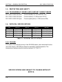
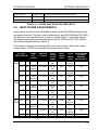
SmartWave T M
AC Power Source
MODELS
SW 10500
SW 15750
SW 21000
Parallel Installation Manual
ELGAR ELECTRONICS CORPORATION
9250 Brown Deer Road
San Diego, CA 92121-2294
1-800-733-5427
Tel: (858) 450-0085
Fax: (858) 458-0267
Email: [email protected]
www.elgar.com
©2000 by Elgar Electronics Corporation
This document contains information proprietary to Elgar Electronics Corporation. The information contained herein
is not to be duplicated or transferred in any manner without prior written permission from Elgar Electronics
Corporation.
September 21, 2004
Document No. M162002-01 Rev D
Elgar One–Year Warranty
Elgar Electronics Corporation (hereinafter referred to as Elgar) warrants its products to be free from defects in
material and workmanship. This warranty is effective for one year from the date of shipment of the product to the
original purchaser. Liability of Elgar under this warranty shall exist provided that:
•
the Buyer exposes the product to normal use and service and provides normal maintenance on the product;
•
Elgar is promptly notified of defects by the Buyer and that notification occurs within the warranty period;
•
the Buyer receives a Return Material Authorization (RMA) number from Elgar’s Repair Department prior to
the return of the product to Elgar for repair, phone 800-73-ELGAR (800-733-5427), ext. 2295;
•
the Buyer returns the defective product in the original, or equivalent, shipping container;
•
if, upon examination of such product by Elgar it is disclosed that, in fact, a defect in materials and/or
workmanship does exist, that the defect in the product was not caused by improper conditions, misuse,
or negligence; and,
•
that Elgar QA seal and nameplates have not been altered or removed and the equipment has not been
repaired or modified by anyone other than Elgar authorized personnel.
This warranty is exclusive and in lieu of all other warranties, expressed or implied, including, but not limited to,
implied warranties of merchantability and fitness of the product to a particular purpose. Elgar, its agents, or
representatives shall in no circumstance be liable for any direct, indirect, special, penal, or consequential loss
or damage of any nature resulting from the malfunction of the product. Remedies under this warranty are
expressly limited to repair or replacement of the product.
CONDITIONS OF WARRANTY
•
To return a defective product, contact an Elgar representative or the Elgar factory for an RMA number.
Unauthorized returns will not be accepted and will be returned at the shipper’s expense.
•
For Elgar products found to be defective within thirty days of receipt by the original purchaser, Elgar will
absorb all ground freight charges for the repair. Products found defective within the warranty period, but
beyond the initial thirty-day period, should be returned prepaid to Elgar for repair. Elgar will repair the unit
and return it by ground freight pre-paid.
•
Normal warranty service is performed at Elgar during the weekday hours of 7:30 am to 4:30 pm Pacific
time. Warranty repair work requested to be accomplished outside of normal working hours will be subject to
Elgar non-warranty service rates.
•
Warranty field service is available on an emergency basis. Travel expenses (travel time, per diem expense,
and related air fare) are the responsibility of the Buyer. A Buyer purchase order is required by Elgar prior to
scheduling.
•
A returned product found, upon inspection by Elgar, to be in specification is subject to an inspection fee
and applicable freight charges.
•
Equipment purchased in the United States carries only a United States warranty for which repair must be
accomplished at the Elgar factory.
Committed to Quality...Striving for Excellence
i
SAFETY NOTICE
Before applying power to the system, verify that the SW Series unit is configured properly for the user’s
particular application.
WARNING!
HAZARDOUS VOLTAGES IN EXCESS OF 280
VRMS, 600V PEAK MAY BE PRESENT WHEN COVERS ARE REMOVED.
QUALIFIED PERSONNEL MUST USE EXTREME CAUTION WHEN
SERVICING THIS EQUIPMENT. CIRCUIT BOARDS, TEST POINTS, AND
OUTPUT VOLTAGES MAY BE FLOATING ABOVE (BELOW) CHASSIS
GROUND.
Installation and service must be performed by qualified personnel who are aware of dealing with attendant
hazards. This includes such simple tasks as fuse verification.
Ensure that the AC power line ground is connected properly to the SW Series unit input connector or
chassis. Similarly, other power ground lines including those to application and maintenance
equipment must be grounded properly for both personnel and equipment safety.
Always ensure that facility AC input power is de-energized prior to connecting or disconnecting the input/output
power cables.
During normal operation, the operator does not have access to hazardous voltages within the
chassis. However, depending on the user’s application configuration, HIGH VOLTAGES
HAZARDOUS TO HUMAN SAFETY may be generated normally on the output terminals. Ensure
that the output power lines are labeled properly as to the safety hazards and that any inadvertent
contact with hazardous voltages is eliminated. To guard against risk of electrical shock during open cover
checks, do not touch any portion of the electrical circuits. Even when the power if off, capacitors can retain an
electrical charge. Use safety glasses during open cover checks to avoid personal injury by any sudden failure of
a component.
Due to filtering, the unit has high leakage current to the chassis. Therefore, it is essential to operate this unit
with a safety ground.
Some circuits are live even with the front panel switch turned off. Service, fuse verification, and
connection of wiring to the chassis must be accomplished at least five minutes after power has been
removed via external means; all circuits and/or terminals to be touched must be safety grounded to
the chassis.
After the unit has been operating for some time, the metal near the rear of the unit may be hot enough to cause
injury. Let the unit cool before handling.
Qualified service personnel need to be aware that some heat sinks are not at ground, but at high potential.
CAUTION!
380V 3-PHASE INPUT POWER SYSTEMS (4 WIRE) MUST
HAVE A NEUTRAL CONNECTION. (FOR UNITS BUILT BEFORE JUNE 2004: THE
NEUTRAL MUST NOT BE SWITCHED. APPLY NEUTRAL BEFORE PHASE VOLTAGE
OR SERIOUS DAMAGE TO THE EQUIPMENT MAY RESULT.)
For safe operation, it is required that output power neutral be connected to chassis ground. The SW system is
shipped with two braided wires on the PDU connected from output power neutral to chassis ground.
ii
SAFETY SYMBOLS
CAUTION
Risk of Electrical Shock
CAUTION
Refer to Accompanying Documents
OFF (Supply)
STANDBY (Supply)
ON (Supply)
iii
TABLE OF CONTENTS
SW 10500/15750/21000
TABLE OF CONTENTS
Warranty.........................................................................................................................................i
Safety Notice ...............................................................................................................................iii
Safety Symbols ...........................................................................................................................iv
Table of Contents.........................................................................................................................v
SECTION I – GENERAL DESCRIPTION
1.1
1.2
1.3
1.4
1.5
1.6
Introduction....................................................................................................................1-1
Input Specifications......................................................................................................1-1
Output Specifications – Normal Operation Mode ....................................................1-1
Measurement System..................................................................................................1-3
Protection and Safety..................................................................................................1-4
1.5.1 Programmable Current Limit/Constant Current Ranges .............................1-4
Physical Specifications ...............................................................................................1-4
1.6.1 Cooling ..............................................................................................................1-4
SECTION 2 – INSTALLATION
2.1
2.2
2.3
2.4
2.5
2.6
2.7
2.8
2.9
Introduction....................................................................................................................2-1
Pre-Installation Inspection ..........................................................................................2-1
Air Intake and Exhaust ................................................................................................2-1
Installation ....................................................................................................................2-2
Input Power Requirements .........................................................................................2-3
2.5.1 Optional SW Input Filter Wiring .....................................................................2-4
Output Connections to the Load ................................................................................2-5
2.6.1 Grounding .........................................................................................................2-5
2.6.2 Chassis Grounding ..........................................................................................2-6
Interconnect Output Power Cables ............................................................................2-6
Slave Interface Cables ...............................................................................................2-6
SW 5250M Rear Panel Ports ....................................................................................2-6
SECTION 3 – OPERATION
3.1
3.2
3.3
iv
Introduction ...................................................................................................................3-1
Power On Sequence ..................................................................................................3-1
Slave Chassis Indicators ............................................................................................3-1
LIST OF FIGURES
2-1
2-2
2-3
2-4
2-5
2-6
2-7
2-8
2-9
2-10
2-11
2-12
2-13
2-14
2-15
2-16
Cabinet Top View........................................................................................................ 2-7
Cabinet Front View, SW 15750 (Slide Mounting) ................................................... 2-8
Cabinet Front View, SW 21000 (Slide Mounting) ................................................... 2-9
Cabinet Side View, SW 15750 (Slide Mounting) ..................................................2-10
Cabinet Side View, SW 21000 (Slide Mounting) ..................................................2-11
Cabinet Side View, SW 15750 (“L” Bracket Mounting)........................................2-12
Cabinet Side View, SW 21000 (“L” Bracket Mounting)........................................2-13
Cabinet Rear View, SW 10500 (Slide Mounting)..................................................2-14
Cabinet Rear View, SW 15750 (Slide Mounting)..................................................2-15
Cabinet Rear View, SW 21000 (Slide Mounting)..................................................2-16
Wiring for SW 10500: 3-Phase Load......................................................................2-17
Wiring for SW 10500: 1-Phase Load......................................................................2-18
Wiring for SW 15750: 3-Phase Load......................................................................2-19
Wiring for SW 15750: 1-Phase Load......................................................................2-20
Wiring for SW 21000: 3-Phase Load......................................................................2-21
Wiring for SW 21000: 1-Phase Load......................................................................2-22
LIST OF TABLES
1-1
1-2
2-1
2-2
Maximum Full Scale Measurement Ranges............................................................. 1-3
Physical Specifications............................................................................................... 1-4
Slides and Mounting Brackets ................................................................................... 2-2
3-Phase Input Power Requirements.......................................................................... 2-3
v
SECTION 1 – GENERAL DESCRIPTION
1.1 INTRODUCTION
The Elgar Models SW 10500, SW 15750, and SW 21000 provide the same high quality
power source as the SW 5250A, but at higher power levels. These systems are comprised
of one master chassis, one or more slave chassis, a power distribution (PDU) chassis, and
an optional input power line filter (required for CE mark).
This parallel installation manual is to be used in conjunction with the operating manual for
the SmartWave Switching Amplifier Model SW 5250A, referred to as the main manual.
The following specifications for the SW 10500, SW 15750, and SW 21000 are identical to
the SW 5250A unless otherwise noted.
1.2 INPUT SPECIFICATIONS
Input Power Ranges: Factory configured 187 to 264 VRMS, 3 phase L-L (3 wire), or
342 to 457 VRMS, 3 phase L-L (4 wire). A chassis ground is also required for safety.
115/230 VRMS selectable, single phase, for power distribution unit (PDU).
Input Power Factor: .6 with USA rectifier, .35 with international rectifier,
.99 with input PFC option.
Input Frequency Range: 47 to 63 Hz.
Efficiency: 70%, minimum, at full load.
Ride Through: 3 mSEC, minimum, 10 mSEC minimum, with PFC option.
1.3 OUTPUT SPECIFICATIONS–NORMAL OPERATION MODE
Power Factor of Load: 0 lagging to 0 leading
AC or DC Output Voltage: 0 to 156 VRMS L-N range 1; 0 to 312 VRMS L-N range 2.
Output Current Per Phase SW 10500: 26A to135V in 156V range, derates linearly to
22.4A @ 156V; 13A to 270V in 312V range, derates linearly to 11.2A @ 312V.
Output Current Per Phase SW 15750: 39A to 135V in 156V range, derates linearly to
33.6A @ 156V; 19.5A to 270V in 312V range, derates linearly to 16.8A @ 312V.
1-1
SECTION 1–GENERAL DESCRIPTION
SW 10500/15750/21000
Output Current Per Phase SW 21000: 52A to 135V in 156V range, derates linearly to
44.8A @ 156V; 26A to 270V in 312V range, derates linearly to 22.4A @ 312V.
Crest Factor: 4.0 (peak output current to RMS output current)
Output Frequency: DC or 40 Hz to 5 KHz.
Output Power Per Phase: SW10500: 3500VA; SW15750: 5250VA; SW21000: 7000VA.
Total Harmonic Distortion (Full Linear Load or No Load): 0.25% maximum, 40 to
100 Hz; 0.5% maximum to 500 Hz; and 1% maximum to 1 KHz plus 1%/KHz to 5 KHz.
AC Noise Level: >60 dB RMS below full output (sine wave, 40 Hz - 500 Hz).
Amplitude Stability with Remote Sense: ±0.1% of full scale over 24 hours at constant
line, load, and temperature.
Load Regulation: ±0.025% of full scale voltage for a full resistive load to no load, above
1 KHz, add ±0.015% KHz.
Line Regulation (DC, or 40 Hz to 5 KHz): ±0.025% of full scale for a ±10% input line
change.
Voltage Accuracy: ±0.1% of range. Above 1 KHz, add 0.2% KHz. Add ±0.1% of full
scale for AC PLUS DC mode. Valid for 5 to 156 VRMS and 10 to 312 VRMS at 25°C
(77°F), sine, sense leads connected.
Voltage Resolution: 0.05% of full scale.
Frequency Resolution: 0.01 Hz 40 to 99.99 Hz
0.05 Hz 100 Hz to 999.9 Hz
0.5 Hz 1000 Hz to 5000 Hz
Frequency Accuracy: ±0.01% at 25°C ±0.001%/°C.
Phase Accuracy, Phase to Phase Balanced Linear Resistive Load:
±1°, 40 Hz to 1 KHz plus ±1°/KHz above 1 KHz.
Phase Angle Resolution: 0.1°.
Remote Output Voltage Sense: 5 VRMS total lead drop, maximum. Sense leads must
be connected at frequency >500 Hz.
Output Impedance: SW 10500: 1 phase; SW 15750 or SW 21000: 1 or 3 phase mode
meets requirements of IEC-1000-3-2, Annex A, supply source. Valid for equipment
classes A, B, C and D.
1-2
SW 10500/15750/21000
SECTION 1–GENERAL DESCRIPTION
1.4 MEASUREMENT SYSTEM
SYSTEM
RMS CURRENT
PEAK
CURRENT
TO 135/270
PEAK
CURRENT
TO 156/312
POWER
VA
SW 10500 1 PHASE
156 Range
0-90A Plus Sign
0-360A Peak
0-310A Peak
0-10800W
0-10800VA
312 Range
0-45A Plus Sign
0-180A Peak
0-155A Peak
0-10800W
0-10800VA
SW 10500 3 PHASE
156 Range
0-30A Plus Sign
0-120A Peak
0-103.4A Peak
0-3600W
0-3600VA
312 Range
0-15A Plus Sign
0-60A Peak
0-51.7A Peak
0-3600W
0-3600VA
SW 15750 1 PHASE
156 Range
0-135A Plus Sign
0-540A Peak
0-465.2A Peak
0-16200W
0-16200VA
312 Range
0-67.5A Plus Sign
0-270A Peak
0-232.6A Peak
0-16200W
0-16200VA
SW 15750 3 PHASE
156 Range
0-45A Plus Sign
0-180A Peak
0-155A Peak
0-5400W
0-5400VA
312 Range
0-22.5A Plus Sign
0-90A Peak
0-77.5A Peak
0-5400W
0-5400VA
SW 21000 1 PHASE
156 Range
0-180A Plus Sign
0-720A Peak
0-620A Peak
0-21600W
0-21600VA
312 Range
0-90A Plus Sign
0-360A Peak
0-310A Peak
0-21600W
0-21600VA
SW 21000 3 PHASE
156 Range
0-60A Plus Sign
0-240A Peak
0-206.8A Peak
0-7200W
0-7200VA
312 Range
0-30A Plus Sign
0-120A Peak
0-103.4A Peak
0-7200W
0-7200VA
TABLE 1-1 MAXIMUM FULL SCALE MEASUREMENT RANGES
NOTE: Accuracies are the same as for the SW 5250A.
1-3
SECTION 1–GENERAL DESCRIPTION
SW 10500/15750/21000
1.5 PROTECTION AND SAFETY
1.5.1 PROGRAMMABLE CURRENT LIMIT/CONSTANT CURRENT RANGES
SW 10500: X2 SW 5250 spec
Currents doubled (i.e. 6.5A becomes 13A)
SW 15750: X3 SW 5250 spec
Currents tripled (i.e. 6.5A becomes 19.5A)
SW 21000: X4 SW 5250 spec
Currents quadrupled (i.e. 6.5A becomes 26A)
1.6 PHYSICAL SPECIFICATIONS
UNIT
HEIGHT
WIDTH
DEPTH
WEIGHT
SW 5250M
8.75" (222 mm)
19" (483 mm)
23.5" (597 mm)
126.5 lbs (57.2 Kg)
SW 5250S
8.75" (222 mm)
19" (483 mm)
23.5" (597 mm)
123.0 lbs (55.8 Kg)
SW PDU
3.50" (89 mm)
19" (483 mm)
18" (457 mm)
22.5 lbs (10.2 Kg)
SW Filter
3.50" (89 mm)
19" (483 mm)
18" (457 mm)
28.1 lbs (12.7 Kg)
TABLE 1-2 PHYSICAL SPECIFICATIONS
1.6.1 COOLING
Air is drawn in from the sides and top of the SW 5250 chassis, and is exhausted from the
rear of the chassis. 200 CFM per chassis is required for specified operation. The
temperature of ambient (inlet) air should not exceed 113° F (45° C).
SPECIFICATIONS ARE SUBJECT TO CHANGE WITHOUT
NOTICE.
1-4
SECTION 2 – INSTALLATION
2.1 INTRODUCTION
The Elgar Model SW 10500, SW 15750, or SW 21000 has been fully calibrated and tested
prior to shipment. The system is designed to be mounted in a standard 19” RETMA
cabinet.
WARNING! The SW 5250S/M weighs over 126 lbs.
(57.2 kg). A minimum two–person lift is required!
WARNING! Hazardous voltages are present when
operating this equipment. Please read the Safety
Notice at the beginning of this manual prior to
installation, operation, or maintenance.
2.2 PRE-INSTALLATION INSPECTION
For unpacking and pre-installation inspection, please refer to the main manual.
2.3 AIR INTAKE AND EXHAUST
The air intakes are located at the top and side panels of the chassis; exhaust air is vented
at the rear. Do not block the side air intakes. The top air intakes improve ventilation.
Special separation is not required when stacking instruments if the recommended slides
are used. However, a 1.75" vertical spacer is required between instruments when using
bottom mounting. The intake air temperature must not exceed 113° F (45° C).
WARNING! Avoid blocking the instrument air intakes
or exhaust. Do not allow hot exhaust air to recirculate
to inlets. Each SW 5250 requires ≥ 200 CFM inlet air,
not to exceed 113° F (45° C).
It is important that the heat produced is properly ventilated to the exterior of the cabinet.
Special baffling to control air flow may be required to prevent hot exhaust air from being
drawn into the air intakes.
2-1
SECTION 2–INSTALLATION
SW 10500/15750/21000
In systems that include an optional cabinet, be careful not to block the air intakes and
exhaust for the cabinet and chassis. Air intakes are located at the front or side cabinet
panels; exhaust air is vented from the top or rear cabinet panels, depending on the cabinet
configuration.
2.4 INSTALLATION
Refer to Figures 2-1 through 2-7 for information on outline and mounting dimensions.
If using slides, locate the secondary mounting rail behind the front mounting rail (see Figure
2-1). Use the slides and mounting kits recommended below in Table 2-1.
24" DEEP
CABINET
ELGAR PN
ACCURIDE
PN
JONATHAN PN ZERO-TRAK PN
SW 5250 Slides (pr)
105-307-16
C-3307-16D
—
—
SW 5250 Brackets
(ea)
105-551-01
—
SPO-551
—
SW PDU Slides (pr)
1066836-20
—
—
C-300S-20
SW Filter Slides (pr)
1066836-20
—
—
C-300S-20
SW 5250 Slides (pr)
105-307-16
C-3307-16D
—
—
SW 5250 Brackets
(ea)
105-551-01
—
SPO-551
—
SW PDU Slides (pr)
1066836-22
—
—
C-300S-22
SW Filter Slides (pr)
1066836-22
—
—
C-300S-22
24" DEEP
CABINET
ELGAR PN
DESCRIPTION
SW 10500
A162001-01
Slide Kit (includes all parts listed above)
SW 10500 CE
A162001-02
Slide Kit (includes all parts listed above)
SW 15750
A162001-03
Slide Kit (includes all parts listed above)
SW 15750 CE
A162001-04
Slide Kit (includes all parts listed above)
SW 21000
A162001-11
Slide Kit (includes all parts listed above)
SW 21000 CE
A162001-12
Slide Kit (includes all parts listed above)
SW 10500
A162001-05
Slide Kit (includes all parts listed above)
SW 10500 CE
A162001-06
Slide Kit (includes all parts listed above)
SW 15750
A162001-07
Slide Kit (includes all parts listed above)
26" DEEP
CABINET
26" DEEP
CABINET
2-2
SW 10500/15750/21000
SECTION 2–INSTALLATION
SW 15750 CE
A162001-08
Slide Kit (includes all parts listed above)
SW 21000
A162001-09
Slide Kit (includes all parts listed above)
SW 21000 CE
A162001-10
Slide Kit (includes all parts listed above)
TABLE 2-1 SLIDES AND MOUNTING BRACKETS
2.5 INPUT POWER REQUIREMENTS
Input power is connected to the SW 5250M (master) and the SW 5250S (slave[s]) via the
rear panel connectors. The input power requirements for each SW 5250M and SW 5250S
are specified on the rear panel cover of each unit; refer to Table 2-7 in the main manual.
The overall system input power requirements for the SW 10500, the SW 15750, and the
SW 21000 are detailed below in Table 2-2.
PDU power is connected via a standard IEC power cord connector. Ensure the voltage
selector switch (115/230) is configured to the required input voltage.
SYSTEM
DESCRIPTION
SW
10500
SW
15750
SW
21000
NUMBE
R OF
PHASES
FREQUENC
Y RANGE
INPUT
PHASE
VOLTAG CURREN
E PHASE/ T (MAX)
PHASE
NEUTRA
L
CURREN
T (MAX)
RECOMMENDE
D CIRCUIT
BREAKER
RATING (MAX)
PFC
USA
3
47-63 Hz
187-264
VAC
50A
Not
required
75A
PFC
INTL
3 and
neutral
47-63 Hz
342-457
VAC
26A
26A
40A
RECT USA
3
47-63 Hz
187-264
VAC
78A
Not
required
100A
RECT INTL
3 and
neutral
47-63 Hz
342-457
VAC
78A
136A
100A
PFC
USA
3
47-63 Hz
187-264
VAC
75A
Not
required
100A
PFC
INTL
3 and
neutral
47-63 Hz
342-457
VAC
39A
39A
50A
RECT USA
3
47-63 Hz
187-264
VAC
117A
Not
required
150A
RECT INTL
3 and
neutral
47-63 Hz
342-457
VAC
117A
204A
150A
PFC
USA
3
47-63 Hz
187-264
VAC
100A
Not
required
125A
PFC
INTL
3 and
neutral
47-63 Hz
342-457
VAC
52A
52A
75A
RECT USA
3
47-63 Hz
187-264
VAC
156A
Not
required
200A
RECT INTL
3 and
neutral
47-63 Hz
342-457
VAC
156A
272A
200A
2-3
SECTION 2–INSTALLATION
neutral
SW 10500/15750/21000
VAC
TABLE 2-2 3-PHASE INPUT POWER REQUIREMENTS
WARNING! An overcurrent protection device
(i.e., circuit breaker) is required in the building
installation. The circuit breaker should be rated for
continuous current as required by the SW system (see
Table 2-2). Installation should comply with local safety
standards.
A device to disconnect the SW 10500, SW 15750, or
SW 21000 from the energy supply source is also
required. This switch or circuit breaker must be close
to the SW system, within easy reach of the operator,
and clearly labeled as the disconnection device for the
SW system.
2.5.1 OPTIONAL SW INPUT FILTER WIRING
Prior to mounting the optional input power line filter (required for CE), pre-wire the input
power to the filter (line side) and pre-wire the filter (load side) to the SW 5250M (master)
and SW 5250S (slave[s]). Input power cable assemblies 5161398-01 are provided to
interface from the filter (load side) to the SW 5250M and SW 5250S chassis inputs. Refer
to Figures 2-8 through 2-16.
Insert the cable assembly end labeled FILTER LOAD SIDE into the filter rear panel cutout,
then secure the cable clamp with the nut. Connect the ring lugs to the filter load side as
indicated by the filter and wire labels. Connect the chassis ground wire to the internal
chassis ground stud. Insert the cable assembly end labeled SW 5250 INPUT into the
master and slave(s) rear panel cutouts, then secure the cable clamp with the nut. Connect
the cable assembly to the SW 5250 input as indicated by the rear panel and wire labels.
Connect the chassis ground wire with ring lug to the chassis ground stud.
An overall shield is provided on each cable from the filter to the SW master or slave(s).
Cable clamps are used to connect this shield at both ends to the chassis.
2-4
SW 10500/15750/21000
SECTION 2–INSTALLATION
2.6 OUTPUT CONNECTIONS TO THE LOAD
Output power is located at the rear of the PDU. Refer to Figures 2-8 through 2-16. For
output connections to the load, refer to Section 2.9 in the main manual. For selection of
wire gauge, refer to Section 2.10 of the main manual.
The PDU output power terminal block is labeled A, B, C, NG , NG , NA, NB, NC . The three
phase power outputs are A, B, and C. The five output neutral terminals are all at the same
potential. However, for EMI purposes, output neutral terminals NA, NB, and NC correspond
respectively to the A, B, and C power outputs. The two NG terminals are for the neutral to
chassis ground.
The output power leads should be shielded and the shield connected to the PDU chassis
using the supplied cable ties to secure the cables and shields to the PDU terminal block
chassis housing. Route the leads out of the system cabinet using the shortest distance
within the cabinet. Once the leads are connected, reinstall the output power terminal block
cover.
Remote sense leads should be used if program frequency is above 500Hz or for improved
performance. Connection of remote sense leads is between the load (or PDU output
terminal block) and the master (SW 5250M) sense terminal block. Refer to Figures 2-11
through 2-16.
The output sense leads should be shielded and the shield connected to the master
chassis. Route the leads out of the system cabinet using the shortest distance within the
cabinet.
2.6.1 GROUNDING
For safe operation, output power neutral must be connected to chassis ground. The SW
system is shipped with two braided wires on the PDU connected from output power neutral
terminals labeled NG to chassis ground. If the neutral exceeds 20V away from the chassis
potential, the unit will shut down.
SAFETY GROUND WARNING!
Output neutral, located on the rear of the PDU, should
be tied to chassis (SAFETY) ground somewhere in the
system. The PDU is shipped with neutral tied to chassis
on the PDU.
2-5
SECTION 2–INSTALLATION
SW 10500/15750/21000
2.6.2 CHASSIS GROUNDING
The master, slave(s), PDU, and optional input filter chassis should be grounded to the
cabinet mounting rails using the chassis ground stud provided on each chassis.
2.7 INTERCONNECT OUTPUT POWER CABLES
Output power is routed from the master and slave(s) chassis to the PDU through 516136601 cable assemblies. Refer to Figures 2-8 through 2-16. Insert the cable clamp, which is
attached to the braided shield, into the master and slave(s) rear panel cutout and secure
with the nut. Connect the spade lugs to the output power terminal block as indicated by the
wire labeling (A, NA, B, NB, C, NC ). The 8-pin power connector at the other end of the cable
assembly is connected to its respective receptacle on the PDU. Use the supplied cable
ties to secure the cables to the PDU terminal block chassis housing. The cable ties should
be secured to the braided shield to ensure a good connection between the shield and the
chassis.
2.8 SLAVE INTERFACE CABLES
The 37-pin D-subminiature slave interface cables (5161408-01) should be routed from the
SLAVE port on the master and slave(s) chassis to the PDU. Refer to Figures 2-8 through
2-10. Use jack screws to secure the cables to the rear panels.
NOTE: Sequencing for the interconnect power cables and slave interface cables must be
observed during installation. Figures 2-2, 2-3, and 2-8 through 2-10 detail the
master, slave1, slave2, and slave3 chassis. This ordering sequence must
coincide with the PDU ports labeled MASTER, SLAVE1, SLAVE2, and SLAVE3.
2.9 SW 5250M REAR PANEL PORTS
The SYNC OUT and CLOCK/LOCK are BNC connectors which require coaxial shielded
cable. The IEEE 488.2, DFI, and EXT IN ports require shielded cables and jack screws to
secure the shields to the SW 5250M chassis. The cables should be routed out of the
system cabinet using the shortest distance within the cabinet.
2-6
SW 10500/15750/21000
SECTION 2–INSTALLATION
CABINET REAR
26.00
MOUNTING RAIL
4.00 2PL
CABINET FRONT
FIGURE 2-1 CABINET TOP VIEW
2-7
SECTION 2–INSTALLATION
SW 10500/15750/21000
FIGURE 2-2 CABINET FRONT VIEW, SW 15750 (Slide Mounting)
2-8
SW 10500/15750/21000
SECTION 2–INSTALLATION
FIGURE 2-3 CABINET FRONT VIEW, SW 21000 (Slide Mounting)
2-9
SECTION 2–INSTALLATION
SW 10500/15750/21000
FIGURE 2-4 CABINET SIDE VIEW, SW 15750 (Slide Mounting)
2-10
SW 10500/15750/21000
SECTION 2–INSTALLATION
FIGURE 2-5 CABINET SIDE VIEW, SW 21000 (Slide Mounting)
2-11
SECTION 2–INSTALLATION
SW 10500/15750/21000
FIGURE 2-6 CABINET SIDE VIEW, SW 15750 (“L” Bracket Mounting)
2-12
SW 10500/15750/21000
SECTION 2–INSTALLATION
FIGURE 2-7 CABINET SIDE VIEW, SW 21000 (“L” Bracket Mounting)
2-13
SECTION 2–INSTALLATION
SW 10500/15750/21000
FIGURE 2-8 CABINET REAR VIEW, SW 10500 (Slide Mounting)
2-14
SW 10500/15750/21000
SECTION 2–INSTALLATION
FIGURE 2-9 CABINET REAR VIEW, SW 15750 (Slide Mounting)
2-15
SECTION 2–INSTALLATION
SW 10500/15750/21000
FIGURE 2-10 CABINET REAR VIEW, SW 21000
(Slide Mounting, No Input Line Filter)
2-16
SW 10500/15750/21000
SECTION 2–INSTALLATION
SHIELD
SHIELD
MASTER
A
O
U
T
P
U
T
I
N
P
U
T
B
C
N
G
A
B
C
N
B
NB
C
NC
G
SENSE
A
NA
G
SHIELD
SHIELD
SHIELD
SLAVE 1
A
O
U
T
P
U
T
I
N
P
U
T
B
C
N
G
SENSE
A
A
B
C
N
A
NA
LOADS
B
NB
B
C
C
NC
G
SHIELD
G
SYSTEM
GROUND
A B C NG N G N A N B N C G
POWER OUT
MASTER
SLAVE 1
PDU
SLAVE 2
A
B
C
N
G
OPTIONAL INPUT
FILTER
SLAVE 3
L
N
G
(REQD FOR CE)
A
B
C
N
G
115/230V IN
POWER IN
(SELECTABLE)
FIGURE 2-11 WIRING FOR SW 10500: 3-PHASE LOAD
2-17
SECTION 2–INSTALLATION
SHIELD
SW 10500/15750/21000
SHIELD
MASTER
A
O
U
T
P
U
T
I
N
P
U
T
B
C
N
G
A
B
C
N
B
NB
C
NC
G
SENSE
A
NA
G
SHIELD
LOAD
A
SHIELD
SHIELD
SLAVE 1
A
O
U
T
P
U
T
I
N
P
U
T
B
C
N
G
SENSE
A
A
B
C
N
NA
B
NB
C
NC
SHIELD
G
G
SYSTEM
GROUND
A B C NG N G N A N B N C G
POWER OUT
MASTER
SLAVE 1
PDU
SLAVE 2
A
B
C
N
G
OPTIONAL INPUT
FILTER
SLAVE 3
L
N
G
(REQD FOR CE)
A
B
C
N
G
115/230V IN
POWER IN
(SELECTABLE)
FIGURE 2-12 WIRING FOR SW 10500: 1-PHASE LOAD
2-18
SW 10500/15750/21000
SECTION 2–INSTALLATION
SHIELD
SHIELD
MASTER
A
O NA
U
B
T
NB
P
U C
T NC
I
N
P
U
T
B
C
N
G
A
G
SENSE
A
B
C
N
G
SHIELD
SHIELD
SHIELD
SLAVE 1
A
O
U
T
P
U
T
I
N
P
U
T
B
C
N
G
A
SHIELD
C
N
G
C
NB
C
NC
SHIELD
N
G
SYSTEM
GROUND
SHIELD
A
O
U
T
P
U
T
I
N
P
U
T
B
C
SLAVE 2
A
B
B
LOADS
B
G
SENSE
A
A
NA
NA
B
NB
A B C NG N G N A N B N C G
POWER OUT
C
NC
MASTER
G
SENSE
A
A
B
C
N
G
OPTIONAL INPUT
FILTER
B
C
N
SLAVE 1
G
PDU
SLAVE 2
SLAVE 3
L
N
G
(REQD FOR CE)
A
B
C
N
G
115/230V IN
POWER IN
(SELECTABLE)
FIGURE 2-13 WIRING FOR SW 15750: 3-PHASE LOAD
2-19
SECTION 2–INSTALLATION
SHIELD
SW 10500/15750/21000
SHIELD
MASTER
A
O
U
T
P
U
T
I
N
P
U
T
B
C
N
G
A
B
C
N
B
NB
C
NC
G
SENSE
A
NA
G
LOAD
SHIELD
A
SHIELD
SHIELD
SLAVE 1
A
O
U
T
P
U
T
I
N
P
U
T
B
C
N
G
A
SHIELD
C
N
G
C
N
C
NC
SYSTEM
GROUND
SHIELD
A
O
U
T
P
U
T
I
N
P
U
T
SHIELD
G
SLAVE 2
A
B
B
B
NB
G
SENSE
A
NA
NA
B
NB
A B C NG NG N A NB NC G
POWER OUT
C
NC
MASTER
G
SENSE
A
A
B
C
N
G
OPTIONAL INPUT
FILTER
B
C
N
SLAVE 1
G
PDU
SLAVE 2
SLAVE 3
L
N
G
(REQD FOR CE)
A
B
C
N
G
115/230V IN
POWER IN
(SELECTABLE)
FIGURE 2-14 WIRING FOR SW 15750: 1-PHASE LOAD
2-20
SW 10500/15750/21000
SECTION 2–INSTALLATION
SHIELD
MASTER A
O NA
I
U
N
B
T
P
NB
P
U
U C
T
T NC
A
B
C
N
G
SHIELD
G
SENSE
A
B
C
N
G
SHIELD
SHIELD
O
U
T
P
U
T
I
N
P
U
T
B
C
N
G
A
SHIELD
N
G
C
LOADS
B
NB
B
C
NC
G
O
U
T
P
U
T
B
C
N
SYSTEM
GROUND
SHIELD
A
NA
B
A B C NG NG NA N B N C G
NB
POWER OUT
C
NC
MASTER
G
SLAVE 1
SENSE
A
C
SHIELD
N
I
N
P
U
T
A
NA
SLAVE 2
A
C
B
A
G
SENSE
B
SHIELD
SLAVE 1
A
PDU
SLAVE 2
G
SLAVE 3
SHIELD
SLAVE 3
A
B
C
N
G
O
U
T
P
U
T
I
N
P
U
T
SENSE
A
A
B
C
N
SHIELD
B
C
N
A
L
N
G
NA
B
115/230V IN
NB
(SELECTABLE)
C
NC
G
G
G
POWER IN
FIGURE 2-15 WIRING FOR SW 21000: 3-PHASE LOAD
2-21
SECTION 2–INSTALLATION
SHIELD
SW 10500/15750/21000
MASTER A
O NA
I
U
N
B
T
P
NB
P
U
U C
T
T NC
A
B
C
N
G
G
SENSE
A
B
C
SHIELD
N
G
LOAD
SHIELD
A
SHIELD
C
N
G
SHIELD
N
G
C
N
G
B
C
A B C NG NG NA NB N C G
POWER OUT
MASTER
G
SENSE
A
A
O NA
U
B
T
N
P B
U C
T NC
I
N
P
U
T
SYSTEM
GROUND
SHIELD
SLAVE 2
A
C
B
SHIELD
G
SENSE
A
A
O NA
U
B
T
P NB
U C
T NC
I
N
P
U
T
B
B
SHIELD
SLAVE 1
A
SLAVE 1
N
G
PDU
SLAVE 2
SLAVE 3
SHIELD
SLAVE 3
A
B
C
N
G
A
B
C
N
B
C
N
L
N
G
A
O NA
U
B
T
N
P B
U C
T NC
I
N
P
U
T
SENSE
A
SHIELD
115/230V IN
(SELECTABLE)
G
G
G
POWER IN
FIGURE 2-16 WIRING FOR SW 21000: 1-PHASE LOAD
2-22
SECTION 3 – OPERATION
3.1 INTRODUCTION
Operating procedures for the SW 10500, SW 15750, and SW 21000 are identical to those
for the standard SW 5250A; the only difference is the VA capacity of the SW 10500, SW
15750, and SW 21000 is two, three, and four times greater (respectively) than for the SW
5250A. Refer to the main manual for detailed operation information.
3.2 POWER ON SEQUENCE
When powering on the system, turn on the front panel power ON switches in the following
sequence: first turn on the PDU, then all SW 5250S slave chassis, and finally the SW
5250M master chassis.
If this sequence is not followed, a fault will be detected and a fault message will be
displayed. To clear the fault, press <ENTER>, then continue the setup process.
3.3 SLAVE CHASSIS INDICATORS
The slave chassis has two indicators, POWER ON and FAULT. If a slave detects a fault in
its own chassis, its FAULT LED will illuminate and it will send a message to the master via
the slave cable.
The master will open all output relays when a fault is detected, and send an error message
to the display. It will also reset the slave fault.
Slave faults are limited to a subset of the system master faults. Fault handling is the same
for all slave faults.
If at any time during operation power to the master is lost or turned off, the FAULT LED on
the front panel of the slave chassis will illuminate and /or the slave chassis will shut down. IF
shutdown occurs, power to the entire system will have to be re-cycled via the front panel
switches (refer to section 3.2 POWER ON SEQUENCE)
3-1
SECTION 3–OPERATION
SW 10500/15750/21000
This page intentionally left blank.
3-2