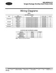
1
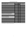
50TFQ004-012
Single Package Rooftop
Heat Pump Units
Wiring Diagrams
DIAGRAM INDEX
DIAGRAM INDEX
Unit 50TFQ
004,005
006
007
008-012
Voltage-Phase-Hertz
208/230-1-60
208/230-3-60
460-3-60
575-3-60
208/230-1-60
208/230-3-60
460-3-60
575-3-60
208/230-3-60
460-3-60
575-3-60
208/230-3-60
460-3-60
575-3-60
UNIT SCHEMATIC
Type
Schematic/Component Arrangement
Schematic/Component Arrangement
Schematic/Component Arrangement
Schematic/Component Arrangement
Schematic/Component Arrangement
Schematic/Component Arrangement
Schematic/Component Arrangement
Schematic/Component Arrangement
Schematic/Component Arrangement
Schematic/Component Arrangement
Schematic/Component Arrangement
Schematic/Component Arrangement
Schematic/Component Arrangement
Schematic/Component Arrangement
From Label Diagram
50DK508797
50DK508798
50DK508801
50DK508804
50DK508797
50DK508799
50DK508802
50DK508805
50DK508800
50DK508803
50DK508806
50DK508808
50DK508809
50DK508810
Figure No.
1
2
3
4
1
5
6
7
8
9
10
11
12
13
ELECTRIC HEAT ACCESSORY WIRING
V-Ph-Hz
208/230-1-60
208/230-3-60, 460-3-60
208/230-1-60
208/230-3-60
460-3-60, 575-3-60
MOCP
< 60 Amps
< 60 Amps
> 60 Amps
> 60 Amps
> 60 Amps
Fig. No.
14
15
16
17
18
Manufacturer reserves the right to discontinue, or change at any time, specifications or designs without notice and without incurring obligations.
PC 111
Catalog No. 535-00062
Printed in U.S.A.
Form 50TFQ-2W
Pg 1
3-03
Replaces: 50TFQ-1W
Book 1 4
Tab 5a 5a
OPTION AND ACCESSORY WIRING
Description
Apollo Controls Wiring — Including Indoor Air Quality
Apollo Thermostat Wiring — Typical
Convenience Outlet Schematic
Durablade Economizer Wiring
Differential Enthalpy Control (Durablade)
Solid-State Enthalpy Control (Durablade)
EconoMi$er Wiring
EconoMi$er Dry Bulb Sensor Wiring
EconoMi$er Enthalpy Sensor Wiring
EconoMi$er Power Exhaust Wiring with Switch in the Actuator
EconoMi$er Power Exhaust Wiring with Switch Outside the Actuator
EconoMi$er2 Wiring
Differential Enthalpy Wiring (EconoMi$er2)
Fire and Smoke Control Wiring (EconoMi$er2)
Indoor Air Quality Sensor Wiring (EconoMi$er2)
Power Exhaust, 208/230V and 575V Units (EconoMi$er2)
Power Exhaust for 460V Units (Economi$er2)
Economi$er2 with PremierLink™ or 4-20 mA Control
Emergency Heat Control with Single-Stage Electric Heater
Emergency Heat Control with Two-Stage Electric Heater
Factory-Installed Non-Fused Disconnect Schematic
Motormaster® I Control Wiring Details
Motormaster II Control Wiring Schematic
Motormaster IV Control Wiring Schematic
Novar Controls Wiring (EMT3051)
Novar Controls Wiring (EMT2024)
PremierLink Controls Wiring
PremierLink Controls Wiring with Dual Terminal Block
Remote Control Panel Wiring
Smoke Detector Shutdown
Time Guard II Device
Two-Position Damper Wiring
62AQ Energy$Recycler Accessory Wiring (Typical)
50TFQ Unit Size
004-012
004-007
008-012
004-012
004-012
004-012
004-012
004-012
004-012
004-012
004-012
004-012
004-012
004-012
004-012
004-012
004-012
004-012
004-012
004-007
008-012
004-007
008-012
004-012
004-012
004-007
008-012
004-007
008-012
004-012
004-012
004-012
004-012
004-012
004-012
004-012
004-012
004-012
Fig. No.
19
20
21
22
23
24
25
26
27
28
29
30
31
32
33
34
35
36
37
38
39
40
41
42
43
44
45
46
47
48
49
50
51
52
53
54
55
56
Serial Number
From 2492Gxxxxx
From 0395Gxxxxx
From 0798Gxxxxx
From 3295Gxxxxx*
From 3295Gxxxxx*
From 3295Gxxxxx*
2099Gxxxxx – 0702Gxxxxx†
2099Gxxxxx – 0702Gxxxxx
2099Gxxxxx – 0702Gxxxxx
2099Gxxxxx – 4501Gxxxxx
4501Gxxxxx – 0702Gxxxxx
From 0802Gxxxxx
From 0802Gxxxxx
From 0802Gxxxxx
From 0802Gxxxxx
From 0802Gxxxxx
From 0802Gxxxxx
From 0802Gxxxxx
From 0395Gxxxxx
From 2900Gxxxxx
From 2900Gxxxxx
From 4601Gxxxxx
From 4002Gxxxxx
From 0802Gxxxxx
*Durablade Economizer was a factory-installed option (FIOP) until 2/15/02; it is currently available only as a field-installed accessory.
†EconoMi$er wiring in Fig. 27 is generic (for units produced from 5/99 to 2/02) with the exception of the way the power exhaust switch is wired.
Refer to Fig. 30 and 31 for more detailed power exhaust switch information.
2
SEQUENCE OF OPERATION
50TFQ004-012 Units
energized and the position of the economizer damper will be
determined by the supply-air temperature. Compressor no. 2
(50TFQ008-012) is locked out.
When the second stage of cooling is satisfied, the compressor,
RVS2, and outdoor-fan motor(s) will be deenergized. The damper position will be determined by the supply-air temperature.
When the first stage of cooling is satisfied, the damper will
move to fully closed position. When using continuous fan, the
damper moves to minimum position.
COOLING UNITS WITH ECONOMI$ER (EconoMi$er,
Johnson Actuator, was produced from Unit Serial Numbers
from 2009Gxxxxx to 0702Gxxxxx) (Sizes 004-007) — When
the outdoor-air temperature (OAT) is above the ECON SP set
point and the room thermostat calls for Stage 1 cooling, terminals G and Y1 are energized. The indoor-fan contactor (IFC),
reversing valve solenoid (RVS1) and compressor contactor
no. 1 (C1) are energized and indoor-fan motor, compressor
no. 1 and outdoor fans start. The EconoMi$er damper modulates to minimum position. The outdoor-fan motor(s) runs
continuously while unit is cooling. After the thermostat is satisfied, the damper modulates to the fully closed position when
the IFM is deenergized.
When the OAT is below the ECON SP setting and the room
thermostat calls for Stage 1 cooling (R to G + Y1), the
EconoMi$er modulates to the minimum position when the
IFM is energized. The EconoMi$er provides Stage 1 of cooling
by modulating the return and outdoor-air dampers to maintain
a 55 F supply air set point. If the supply-air temperature (SAT)
is greater than 57 F, the EconoMi$er modulates open, allowing
a greater amount of outdoor air to enter the unit. If the SAT
drops below 53 F, the outdoor air damper modulates closed to
reduce the amount of outdoor air. When the SAT is between 53
and 57 F, the EconoMi$er maintains its position.
If outdoor-air alone cannot satisfy the cooling requirements of
the conditioned space, and the OAT is above the MECH CLG
LOCKOUT set point, the EconoMi$er integrates free cooling with
mechanical cooling. This is accomplished by the strategies below.
NOTE: Compressor has a 2-minute Minimum On, Minimum
Off, and Interstage delay timer.
1. If Y1 is energized, and the room thermostat calls for Y2
(2-stage thermostat), the compressor, RVS1 and OFM are
energized. The EconoMi$er damper is maintained at its
current position.
2. If Y1 is energized for more than 20 minutes, and Y2 is not
energized (whether or not a 2-stage thermostat is used), the
compressor, RVS1 and OFM are energized. The
EconoMi$er damper is maintained at its current position.
3. If Y1 is energized, the compressor and RVS1 are already
energized (see Step 2) and the room thermostat calls for
Y2, the compressor continues to operate.
4. If compressor and RVS1 are energized and the thermostat
is satisfied, the compressor, RVS1, the OFM, and IFM are
deenergized and the EconoMi$er modulates closed.
When the OAT is below the MECH CLG LOCKOUT set
point, the compressors remain off.
COOLING, UNITS WITH ECONOMI$ER (EconoMi$er,
Johnson Actuator, was produced from Unit Serial Numbers
from 2009Gxxxxx to 0702Gxxxxx) (Sizes 008-014) — When
the outdoor-air temperature (OAT) is above the ECON SP set
point and the room thermostat calls for Stage 1 cooling, terminals G and Y1 are energized. The indoor-fan contactor (IFC),
reversing valve solenoid (RVS1) and compressor contactor
no. 1 (C1) are energized and indoor-fan motor, compressor
no. 1 and outdoor fans start. The EconoMi$er damper modulates to minimum position. The outdoor-fan motor(s) runs
continuously while unit is cooling. After the thermostat is satisfied, the damper modulates to the fully closed position when
the IFM is deenergized.
COOLING, UNITS WITHOUT ECONOMIZER — When
thermostat calls for cooling, terminals G and Y1 are energized.
The indoor-fan contactor (IFC), reversing valve solenoid
(RVS1) and compressor contactor no. 1 (C1) are energized and
indoor-fan motor, compressor no. 1, and outdoor fans start. The
outdoor-fan motor(s) run continuously while unit is cooling.
On 50TFQ008-012 units, if the thermostat calls for a secondstage of cooling by energizing Y2, compressor contactor no. 2
(C2) and reversing valve solenoid (RVS2) are energized and
compressor no. 2 starts.
HEATING, UNITS WITHOUT ECONOMIZER (Sizes
(004-007) — Set system switch at AUTO. or HEAT position.
Set thermostat at desired temperature.
When the thermostat calls for heat, the IFC, outdoor-fan
contactor (OFC), and compressor contactor are energized. The
RVS is deenergized and switches position, and the indoor fan,
outdoor fan, and compressor are energized.
If the thermostat calls for a second stage of heat, the heater
contactor (HC) is energized and starts the electric heaters.
When the space temperature approaches the heating temperature set point, heating stages cycle off.
HEATING, UNITS WITHOUT ECONOMIZER (Sizes
008-012) — Upon a request for heating from the space
thermostat, terminal W1 will be energized with 24 v. The IFC,
outdoor-fan contactor (OFC), C1, and C2 will be energized.
The reversing valves switch position and deenergize, and the
indoor fan, outdoor fan, compressor no. 1, and compressor
no. 2 are energized.
If the space temperature continues to fall while W1 is
energized, W2 will be energized with 24 v, and the heater
contactor(s) (HC) will be energized, which will energize the
electric heater(s).
When the space thermostat is satisfied, W2 will be
deenergized first, and the electric heater(s) will be deenergized.
Upon a further rise in space temperature, W1 will be
deenergized, and the compressors will turn off.
COOLING, UNITS WITH DURABLADE ECONOMIZER — When the outdoor-air temperature is above the
outdoor-air thermostat (OAT) setting and the room thermostat
calls for cooling, compressor contactor no. 1 is energized to
start compressor no. 1 and the outdoor-fan motor(s). RVS1
(reversing valve solenoid) is energized. The indoor-fan motor
is energized and the economizer damper moves to the
minimum position. Upon a further call for cooling, compressor
contactor no. 2 will be energized (50TFQ008-012), starting
compressor no. 2. RVS2 is energized. After the thermostat is
satisfied, the damper moves to the fully closed position. When
using continuous fan, the damper moves to minimum position.
When the outdoor-air temperature is below the OAT setting
and the thermostat calls for cooling, the economizer dampers
move to the minimum position. If the supply-air temperature is
above 57 F, the damper continues to open until it reaches the
fully open position or until the supply-air temperature drops
below 52 F.
When the supply-air temperature falls to between 57 F and
52 F, the damper will remain at an intermediate open position.
If the supply-air temperature falls below 52 F, the damper will
modulate closed until it reaches the minimum position or until
the supply-air temperature is above 52 F. When the thermostat
is satisfied, the damper will move to the fully closed position.
When using continuous fan, the damper moves to minimum
position.
If the outdoor air alone cannot satisfy the cooling requirements
of the conditioned space, economizer cooling is integrated with
mechanical cooling, providing second-stage cooling. Compressor
no. 1 reversing valve solenoid (RVS1) and the outdoor fan will be
3
HEATING, UNITS WITH ECONOMIZER INCLUDING
DURABLADE, ECONOMI$ER (Johnson) OR ECONOMI$ER2 (Sizes 008-012) — Upon a request for heating from
the space thermostat, terminal W1 will be energized with 24 v.
The IFC, outdoor-fan contactor (OFC), C1, and C2 will be
energized. The reversing valves switch position and the indoor
fan, outdoor fan, compressor no. 1, and compressor no. 2 are
energized. The economizer damper blade opens to minimum
position.
If the space temperature continues to fall while W1 is
energized, W2 will be energized with 24 v, and the heater
contactor(s) (HC) will be energized, which will energize the
electric heater(s).
When the space thermostat is satisfied, W2 will be deenergized first, and the electric heater(s) will be deenergized.
Upon a further rise in space temperature, W1 will be
deenergized, and the reversing valve solenoids (RVS1 and
RVS2) will be energized.
DEFROST (Sizes 004-007) — As frost builds up on the outdoor coil, the coil temperature drops below 28 F. When this
outdoor-coil temperature drop is sensed by the defrost thermostat (DFT) and the defrost timer is at the end of a timed period
(adjustable at 30, 50, or 90 minutes), the unit operates in a
defrost cycle controlled by the defrost timer and thermostat.
During this cycle, the reversing valve solenoid (RVS) is
energized and the outdoor fan shuts off. The electric heaters (if
installed) will be energized.
The unit continues to defrost until the coil temperature as
measured by DFT reaches 65 F, or the duration of defrost cycle
completes a 10-minute period.
At the end of the defrost cycle, the electric heaters (if
installed) and the reversing valve will be deenergized, and the
outdoor-fan motor will be energized. The unit will now operate
in the Heating mode.
If the thermostat is satisfied during a defrost cycle, the unit
will continue in the Defrost mode until the time or temperature
constraints are satisfied.
DEFROST (Sizes 008-012) — When the temperature of the
outdoor coil drops below 28 F as sensed by the defrost thermostat (DFT2) and the defrost timer is at the end of a timed period
(adjustable at 30, 50, or 90 minutes), reversing valve solenoids
(RVS1 and RVS2) are energized and the OFC is deenergized.
This switches the position of the reversing valves and shuts
off the outdoor fan. The electric heaters (if installed) will be
energized.
The unit continues to defrost until the coil temperature as
measured by DFT2 reaches 65 F, or the duration of defrost
cycle completes a 10-minute period.
During the Defrost mode, if circuit 1 defrosts first, RVS1
will oscillate between Heating and Cooling modes until the
Defrost mode is complete.
At the end of the defrost cycle, the electric heaters (if
installed) will be deenergized; the reversing valves switch and
the outdoor-fan motor will be energized. The unit will now
operate in the Heating mode.
If the space thermostat is satisfied during a defrost cycle, the
unit will continue in the Defrost mode until the time or temperature constraints are satisfied.
When the OAT is below the ECON SP setting and the room
thermostat calls for Stage 1 cooling (R to G + Y1), the
EconoMi$er modulates to the minimum position when the
IFM is energized. The EconoMi$er provides Stage 1 of cooling
by modulating the return and outdoor-air dampers to maintain
a 55 F supply air set point. If the supply-air temperature (SAT)
is greater than 57 F, the EconoMi$er modulates open, allowing
a greater amount of outdoor air to enter the unit. If the SAT
drops below 53 F, the outdoor air damper modulates closed to
reduce the amount of outdoor air. When the SAT is between 53
and 57 F, the EconoMi$er maintains its position.
If outdoor-air alone cannot satisfy the cooling requirements
of the conditioned space, and the OAT is above the MECH
CLG LOCKOUT set point, the EconoMi$er integrates free
cooling with mechanical cooling. This is accomplished by the
strategies below.
NOTE: Compressors have a 2-minute Minimum On,
Minimum Off, and Interstage delay timer.
1. If Y1 is energized, and the room thermostat calls for Y2
(2-stage thermostat), compressor no. 1, RVS1 and OFM
are energized. The EconoMi$er damper is maintained at
its current position.
2. If Y1 is energized for more than 20 minutes, and Y2 is
not energized (whether or not a 2-stage thermostat is
used), compressor no. 1, RVS1 and OFM are energized.
The EconoMi$er damper is maintained at its current
position.
3. If Y1 is energized, and compressor no. 1 is already
energized (see Step 2) and the room thermostat calls for
Y2, compressor no. 1 continues to operate. If Y2 remains
energized for more than 20 minutes, compressor no. 2
and RVS2 are energized.
NOTE: Compressor no. 2 cannot be energized unless
there is a signal for Y2 from the space thermostat.
4. If compressor no. 2 is energized, and the Y2 signal from
the thermostat is satisfied, compressor no. 1 and 2, RVS1,
RVS2 and ODF are deenergized. Reasserting Y2 will
start compressor no. 1 and (after a 20-minute interstage
delay) compressor 2.
5. If compressor no. 1 is energized and the thermostat is satisfied, compressor no. 1, the OFM, RVS1 and IFM are
deenergized and the EconoMi$er modulates closed.
HEATING, UNITS WITH ECONOMIZER INCLUDING
DURABLADE, ECONOMI$ER (Johnson) OR ECONOMI$ER2 (Sizes 004-007) — Set system switch at AUTO. or
HEAT position. Set thermostat at desired temperature.
When the thermostat calls for heat, the IFC, outdoor-fan
contactor (OFC), and compressor contactor are energized. The
economizer damper blade opens to minimum position. The
RVS is deenergized and switches position, and the indoor fan,
outdoor fan, and compressor are energized.
If the thermostat calls for a second stage of heat, the heater
contactor (HC) is energized and starts the electric heaters.
When the space temperature approaches the heating temperature set point, heating stages cycle off. The reversing valve
solenoid is reenergized.
4
LEGEND
AHA
AWG
BR
C
CAP
CB
CC
CH
CLO
CO2
COC
COH
COM
COMMS
COMP
CR
CTD
D
DAT
DB
DFT
DM
DR
DX
EC
ECON
EFC
EPS
EQUIP
ER
FC
FPT
FU
GND
GVR
HC
HM
HPS
HR
HTR
HV TRAN
I
IAQ
IFC
IFM
IFMOVL
IFR
IGC
LED
LPS
LSM
—
—
—
—
—
—
—
—
—
—
—
—
—
—
—
—
—
—
—
—
—
—
—
—
—
—
—
—
—
—
—
—
—
—
—
—
—
—
—
—
—
—
—
—
—
—
—
—
—
—
—
LTLO
MCA
MGV
MTR
NC
NEC
NO
OAT
OATC
OATH
OCR
OFC
OFM
OLR
P, PL
QT
R
RVS
SAT
SW
SW1
SW2
SW3
SW4
TB
TC
TDR
TH
TRAN
VVT®
Adjustable Heat Anticipator
American Wire Gage
Blower Relay
Contactor, Compressor
Capacitor
Circuit Breaker
Cooling Compensator
Crankcase Heater
Compressor Lockout
Carbon Dioxide
Cool Changeover Relay
Heat Changeover Relay
Common
Communications
Compressor Motor
Control Relay
Compressor Time Delay
Diode
Discharge Air Thermistor
Defrost Board
Defrost Thermostat
Damper Motor
Defrost Relay
Direct Expansion
Enthalpy Control
Economizer
Exhaust Fan Contactor
Emergency Power Supply
Equipment
Economizer Relay
Fan Contactor
Freeze Protection Thermostat
Fuse
Ground
Gas Valve Relay
Heater Contactor (Electric Heater)
Humidity Relay
High-Pressure Switch
Heater Relay
Heater
High-Voltage Transformer
Ignitor
Indoor Air Quality
Indoor-Fan Contactor
Indoor-Fan Motor
Indoor-Fan Motor Overload Switch
Indoor-Fan Relay
Integrated Gas Controller
Light Emitting Diode
Low-Pressure/Loss-of-Charge Switch
Limit Switch (Manual Reset)
—
—
—
—
—
—
—
—
—
—
—
—
—
—
—
—
—
—
—
—
—
—
—
—
—
—
—
—
—
—
Low Temp Cooling Lockout
Minimum Circuit Amps
Main Gas Valve
Motor
Normally Closed
National Electrical Code
Normally Open
Outdoor-Air Thermostat
Outdoor Air Thermostat (Cool)
Outdoor Air Thermostat (Heat)
Occupied Relay
Outdoor-Fan Contactor
Outdoor-Fan Motor
Overload Relay
Plug
Quadruple Terminal
Relay
Reversing Valve Solenoid
Supply-Air Thermostat
Switch
Switch, Fully Open
Switch, Fully Closed
Switch Minimum Vent Position
Switch Maximum Vent Position
Terminal Block
Thermostat, Cooling
Time-Delay Relay
Thermostat, Heating
Transformer
Variable Volume/Variable Temperature
Field Splice
Terminal (Marked)
Marked Wire
Terminal (Unmarked)
Terminal Block
Splice
Splice Marked
Factory Wiring
Field Control Wiring
Field Power Wiring
Accessory or Optional Wiring
To indicate common potential only.
Not to represent wiring.
5
NOTES FOR FIG. 1
1. If any of the original wire furnished must be replaced, it must be
replaced with Type 90 C wire or its equivalent.
2. Thermostat:
HH07AT170, 172, 174, and P272-2783.
Subbase:
HH93AZ176, 178 and P272-1882, 1883.
3. Set heat anticipator at .8 amp for 1st stage and .3 amp for 2nd
stage.
4. Use copper conductors only.
5. Use copper, copper-clad aluminum or aluminum conductors.
6.
CB
MUST
VOLTAGE
TRIP
RATING
MFG. PT. NO.
AMPS
Potter & Brumfield
24 V
3.2
W2BX-1024-3.2
NOTES FOR FIG. 2, 8, 11, 12, 13
1. If any of the original wire furnished must be replaced, it must be
replaced with Type 90 C wire or its equivalent.
2. Three-phase motors are protected under primary single phasing conditions.
3. Thermostat:
HH07AT170, 172, 174, and P272-2783.
Subbase:
HH93AZ176, 178, and P272-1882, 1883.
4. Set heat anticipator at .8 amp for 1st stage and .3 amp for 2nd
stage.
5. Use copper conductors only.
6. Use copper, copper-clad aluminum or aluminum conductors.
7.
CB
VOLTAGE
MUST
RATING
MFG. PT. NO.
TRIP
AMPS
Potter & Brumfield
24 V
W2BX-1024-3.2
3.2
NOTES FOR FIG. 3, 4, 6, 7, 9, 10
5. Use copper conductors only.
6.
CB
VOLTAGE
RATING
MFG. PT. NO.
1. If any of the original wire furnished must be replaced, it must be
replaced with Type 90 C wire or its equivalent.
2. Thermostat:
HH07AT170, 172, 174, and P272-2783
Subbase:
HH93AZ176, 178, and P272-1882, 1883.
3. Three-phase motors are protected under primary singlephasing conditions.
4. Set heat anticipator at .8 amp for 1st stage and .3 amp for 2nd
stage.
24 V
Potter & Brumfield
W2BX-1024-3.2
MUST
TRIP
AMPS
3.2
NOTES FOR FIG. 5
5. Use copper conductors only.
6. Use copper, copper-clad aluminum or aluminum conductors.
7.
CB
MUST
VOLTAGE
TRIP
RATING
MFG. PT. NO.
AMPS
Potter & Brumfield
24 V
3.2
W2BX-1024-3.2
1. If any of the original wire furnished must be replaced, it must be
replaced with Type 90 C wire or its equivalent.
2. Thermostat:
HH07AT170, 172, 174, and P272-2783
Subbase:
HH93AZ176, 178, and P272-1882, 1883.
3. Three-phase motors are protected under primary singlephasing conditions.
4. Set heat anticipator at .8 amp for 1st stage and .3 amp for 2nd
stage.
6
Fig. 1 — Schematic/Component Arrangement; 50TFQ004-006; 208/230-1-60
7
SEE NOTE#3 AND 4
Fig. 2 — Schematic/Component Arrangement; 50TFQ004,005; 208/230-3-60
8
Fig. 3 — Schematic/Component Arrangement; 50TFQ004,005; 460-3-60
9
Fig. 4 — Schematic/Component Arrangement; 50TFQ004,005; 575-3-60
10
Fig. 5 — Schematic/Component Arrangement; 50TFQ006; 208/230-3-60
11
Fig. 6 — Schematic/Component Arrangement; 50TFQ006; 460-3-60
12
Fig. 7 — Schematic/Component Arrangement; 50TFQ006; 575-3-60
13
Fig. 8 — Schematic/Component Arrangement; 50TFQ007; 208/230-3-60
14
Fig. 9 — Schematic/Component Arrangement; 50TFQ007; 460-3-60
15
Fig. 10 — Schematic/Component Arrangement; 50TFQ007; 575-3-60
16
Fig. 11 — Schematic/Component Arrangement; 50TFQ008-012; 208/230-3-60
17
Fig. 12 — Schematic/Component Arrangement; 50TFQ008-012; 460-3-60
18
Fig. 13 — Schematic/Component Arrangement; 50TFQ008-012; 575-3-60
19
NO SINGLE POINT BOX REQUIRED OR CRSINGLE001A00
Fig. 14 — Electric Heater Power Wiring Connections
Electric Cooling Units — 208/230-1-60 — Less Than 60 Amps MOCP
NO SINGLE POINT BOX REQUIRED (Use Existing Space in Unit) OR
CRSINGLE001A00 (Sizes 3 to 6 Tons) OR
CRSINGLE006A00 (Sizes 71/2 and 81/2 Tons) OR
CRSINGLE011A00 (Size 10 Tons)
Fig. 15 — Electric Heater Power Wiring Connections
Electric Cooling Units — 208/230-3-60, 460-3-60 — Less Than 60 Amps MOCP
CRSINGLE004A00
CRSINGLE005A00
Fig. 16 — Electric Heater Power Wiring Connections —
Heat Pump Units, 208/230-1-60 — Greater Than 60 Amps MOCP
20
CRSINGLE002A00 OR
CRSINGLE007A00 OR
CRSINGLE012A00
CRSINGLE003A00 OR
CRSINGLE009A00 OR
CRSINGLE015A00
CRSINGLE013A00
CRSINGLE017A00
Fig. 17 — Electric Heater Power Wiring Connections —
Heat Pump Units, 208/230-3-60 — Greater Than 60 Amps MOCP
CRSINGLE008A00 AND
CRSINGLE014A00
CRSINGLE010A00 AND
CRSINGLE016A00
Fig. 18 — Electric Heater Power Wiring Connections —
Heat Pump Units, 460-3-60 and 575-3-60 — Greater Than 60 Amps MOCP
21
22
FILTER
STATUS
HUMIDITY
SENSOR
GRN
BLK
GRN
BLK
2 1
87654321
BLK
RED
BLK
RED
GRN
#11
#10
#10
#11
NC
COM
NO
OAT
SAT
COOL
2
RELAY
SINGLE ZONE RELAY PACK CIRCUIT BOARD
1
13
12
11
10
9
8
7
4
3
FAN
RV
6
FIELDHEAT
INSTALLED 5
JUMPERS†† 4
3
SINGLE ZONE
2
RELAY PACK
1
WITH AUXILARY
YEL
WHT
BLK
AO
COM
Y1
Y2
G
B1
LED
COM
DAT
COM
REM POT
COM
CO2 COM
CO2+
OAT
COM
OAH
+15V
CLG1
RAT
CLG2
COM
CONTROLLER
RAH
+15V
24 VAC
24 COM
GND
VIO
PNK
TAN
VIO
WHT
RED
DAT
EC
ACCESSORY
ONLY
OAT
FAN
HEAT 2
HEAT 1 NC
HEAT 1
HEAT/FAN COM
COOL 2
COOL 1
COOL COM
R
24 VAC/10 VA
C
GROUND
AUXILIARY
RELAY**
TO CARRIER
HVAC UNIT
FIELD SUPPLIED
WIRING
*Filter status switch and humidity sensor cannot function simultaneously. Only one sensor can be wired.
†Such as a CO2 sensor.
**Set auxiliary option to ‘‘2’’ — IAQ Control per VTS or VVT Installation
Instructions.
††Field-installed Jumpers between 3,4 and 5,7.
NOTE: When single zone relay pack is used on a VVT Monitor Only
System, the monitor thermostat cannot control a damper.
DM
Fig. 19 — Apollo Controls Wiring — Including Indoor-Air Quality
DX
FAN STATUS
1
2
3
4
5
6
7
8
9
10
11
12
13
14
15
16
17
ALARM
RELAY
CONTACTS
+ 2-10VDC
- SIG COM (J5-3)
+ 4-20mA (J5-2)
WHT
RED
BLU
YEL
GRN
IAQ STATUS†
INDOOR AIR QUALITY (CO2) SENSOR
(33ZCSENCO2) TYPICAL WIRING DIAGRAM
H G 24 VAC
OR
+ - 24 VDC
ADDITIONAL SENSORS*
TSP01
TERMINAL
NUMBER
WHT #1
RED #2
REMOTE ROOM
TEMP. SENSOR
NETWORK
GROUND
24 V
TRAN
24 VAC
20 VA
(FIELD
SUPPLIED)
RED
BRN
GRN
BLU
PNK
ECONOMI$ER OPTION/ACCESSORY
Fig. 20 — Apollo Thermostat Wiring — 50TFQ004-007 (Typical)
Fig. 21 — Apollo Thermostat Wiring — 50TFQ008-012 (Typical)
23
Fig. 22 — Convenience Outlet Schematic
Fig. 23 — Durablade Economizer Schematic
24
A
B
TR
C
D SO
TR1
SR
+
2
+
24 VAC SUPPLY FROM
24 VAC SUPPLY FROM
ECONOMIZER CONTROL
SECTION (RED TO TR,
BRN TO TR1)
A
TO SENSOR MOUNTED
ON BACK OF CONTROL
B
S (HH57AC078
+ SENSOR)
3
1
GRAY WIRE FROM
ECONOMIZER HARNESS
TR
TR1
C SO
D
+
SR
+
2
3
CONTROL
} ECONOMIZER
SECTION (RED TO TR,
BRN TO TR1)
SENSOR MOUNTED
} TO
ON BACK OF CONTROL
620 ohm
JUMPER
GRAY WIRE FROM
ECONOMIZER HARNESS
1
LED
LED
RED WIRE FROM
ECONOMIZER SWITCH 3
(NORMALLY CLOSED)
RED WIRE FROM
ECONOMIZER SWITCH 3
(NORMALLY CLOSED)
NOTE: Switches shown in the high enthalpy state. Terminals 2 and 3 close on enthalpy decrease.
NOTES:
1. Remove factory-installed jumper across SR and +
before connecting wires from HH57AC078 sensor.
2. Switches shown in high outdoor-air enthalpy state.
Terminals 2 and 3 close on low outdoor air enthalpy
relative to indoor air enthalpy.
Fig. 25 — Wiring Connections for
Solid-State Enthalpy Control
(Durablade Economizer)
Fig. 24 — Wiring Connections for
Differential Enthalpy Control
(Durablade Economizer)
*Wiring is generic for all EconoMi$ers with the exception of the actuator. Refer to Fig. 29 and 30 for specific actuator production dates.
Fig. 26 — EconoMi$er Wiring for Units Produced 5/1999 through 2/2002*
25
ECONOMI$ER
CONTROLLER
BROWN
VIOLET
OAT
WHITE
RED
COM
OAH
+15 V
RAT
COM
RAH
+15 V
CO2 (+)
CO2 COM
DAT
COM
REM POT
COM
LED
COM
BROWN
VIOLET
WHITE
RED
TEMP
TEMP
COM
OUT
PWR
OUTDOOR
AIR
SENSOR
TEMP
TEMP
COM
OUT
PWR
RETURN
AIR
SENSOR
CO2 SENSOR
24
V+
COM VAC
SUPPLY AIR
TEMPERATURE SENSOR
PINK
TEMP
VIOLET
TEMP
Fig. 27 — EconoMi$er Dry Bulb Sensor Wiring
Fig. 28 — Wiring Diagram for Field-Installed Enthalpy Sensors
26
RED
GRAY
H1
H2
X4
X2 X3
RED YEL BLU GRAY
HT01AH850
(460 VAC)
HT01AH859
(575 VAC)
TO FUSED
DISCONNECT
X1
H1
H3 H2
H4
X4
X2 X3
X1
SECONDARY
230VAC
SECONDARY
230VAC
FIELD SUPPLIED
WIRING
BLACK
BLACK
COMPRESSOR 1
CONTACTOR
OR
11
LT. BLUE
21
230VAC
13
BROWN
23
FAN 1
C1
GREEN/
YELLOW
4-PIN
CONNECTOR
PLUG
2 x 4 IN.
HANDY BOX
BLACK L1
1
BLUE
L2 2
GREEN GND
3
4
3
6
9
2
5
8
1
4
7
B
BLACK
R1
24 VAC
A
BLUE
L1
1
L2
2
GND
3
4
230 VAC
1 PHASE
3-PIN
CONNECTOR
PLUG
ORANGE
1
YELLOW
2
BROWN
BLACK
BLACK
BLUE
LT. BLUE
GREEN
BROWN
FAN 2
3
6
9
2
5
8
1
4
7
B
BLACK
C1
GREEN/
YELLOW
R2
24 VAC
A
BLUE
Fig. 29 — EconoMi$er Power Exhaust with the Switch Inside the Actuator
(Units Produced 5/16/1999 - 11/5/2001)
TOP SWITCH
CAM
POSITION
INDICATOR
TOP
SWITCH
WIRE TIE
ANCHOR HOLE
BOTTOM
SWITCH
CONNECTS TO
2-PIN CONNECTOR
IN ECONOMIZER
2
1
+24 VAC
RED
TOP
SWITCH
NC
NO
COM
COM
RED
BOTTOM
SWITCH
NC
NO
ORANGE
YELLOW
BROWN
1
2
CONNECTS TO THE
3-PIN CONNECTOR
PLUG ON POWER EXHAUST
3
COM
Fig. 30 — EconoMi$er Power Exhaust with Switch Outside of Actuator
(Units Produced 11/5/2001 - 2/15/2002)
27
3
ECONOMISER2 CONTROLLER
ACTUATOR
NOTE 9
RED
24 VAC HOT
BLACK
24 VAC COM
BROWN
BLACK
TR
TAN
RUN
SO
+
SR
+
820 OHM NOTE 6
RESISTOR
VIOLET
NOTE 1
ECONOMIZER
DRY BULB
SENSOR
620 OHM
RESISTOR NOTE 5
BLACK
5
1K
1S
+
WHITE
NOTE 4
+
-
1
2
3
4
T
T1
P
P1
WHITE
Compressor Lockout N.C.
2K
2-10V
OUT
4
BROWN
3
BLACK
GRAY
5
GRAY
BLUE
2
BLUE
YELLOW
8
YELLOW
VIOLET
6
VIOLET
PINK
7
PINK
1
RED
10
WHITE
11
BROWN
9
ORANGE
TR1
NOTE 7
1S1
-
MINIMUM
POSITION
ADJUSTMENT
FREE
COOL
Q
MAXIMUM
POSITION
ADJUSTMENT
AQ
Q1
AQ1
SD1
AC
AC1
PG
PG1
+
2-10 VDC
NOTE 2
CO2 SENSOR
UNIT
CONTROL
EXHAUST
FAN
INDOOR
FAN
12
}
SD
-
NOTE 8
HARNESS
AND PLUG NOTE 3
NOTES:
1. The standard EconoMi$er2 is shipped with a fixed dry bulb sensor. (Open 67 F — Close 52 F.) An adjustable dry bulb or enthalpy sensor can
replace the fixed dry bulb. (See Note 6.)
2. CO2 sensor is optional. Field-installed accessory. See rooftop price pages for ordering data and pricing. Power for CO2 sensor should be provided by field-supplied transformer.
3. The HVAC unit is shipped with a jumper plug attached to the EconoMi$er2 harness. Remove the jumper plug and save for future use if economizer is removed. Connect the male side of plug (shown above) to the female side in HVAC unit.
4. 1S is an electronic switch that closes when powered by a 24 vac input.
5. Factory-installed 620-ohm, 1 watt, 5% resistor should be removed only when a HH57AC078 enthalpy sensor or CROASENR001A00 adjustable dry bulb is added to SR and + for differential sensing.
6. When replacing the fixed dry bulb sensor with an enthalpy or adjustable dry bulb, remove the 820-ohm resistor.
7. Compressor lockout (Open 35 F — Close 50 F).
8. See EconoMi$er2 Installation Instructions for details on locating and wiring supply air (mixed air) sensor.
9. Switch on actuator must be in run position for economizer to operate.
10. A 2-stage thermostat is recommended.
11. Before troubleshooting wiring, ensure that all the correct sensors have been installed (refer to EconoMi$er2 Installation Instructions).
Fig. 31 — EconoMi$er2 Wiring (For Units Produced 2/18/02 - Present)
ECONOMISER2
CONTROLLER
TAN
VIOLET
SO +
+
S
SR +
TAN
VIOLET
+
S
HH57AC078 ENTHALPY OR
CROASENPOO1A00
ADJUSTABLE
DRY BULB
(NOTE 1)
HH57AC078 DIFFERENTIAL
ENTHALPY OR
CROASENPOO1A00
DIFFERENTIAL
ADJUSTABLE DRY BULB
(NOTE 2)
NOTES:
1. Violet wire from SO terminal has a factory-installed 820-ohm in-line
resistor. This resistor must be removed when replacing the standard
fixed dry bulb with an optional enthalpy or adjustable dry bulb.
2. The standard economizer has a 620-ohm resistor between terminals SR
and +. This resistor must be removed when adding differential enthalpy
or differential adjustable dry bulb.
Fig. 32 — Differential Enthalpy Wiring for EconoMi$er2
28
ECONOMISER2
ACTUATOR
ECONOMISER2 CONTROLLER
RED
24 VAC HOT
BLACK
24 VAC COM
BROWN
BLACK
TR
TR1
SO
+
4
BROWN
3
BLACK
GRAY
5
GRAY
BLUE
2
BLUE
YELLOW
8
YELLOW
VIOLET
6
VIOLET
PINK
7
PINK
1
RED
10
WHITE
11
BROWN
9
ORANGE
TAN
SR
+
BLACK
820 OHM
RESISTOR
VIOLET
ECONOMISER2
DRY BULB
SENSOR
620 OHM
RESISTOR
5
1K
1S
+
WHITE
+
2
3
4
T
T1
P
P1
WHITE
Compressor Lockout N.C.
2K
2-10V
OUT
-
1
1S1
-
MINIMUM
POSITION
ADJUSTMENT
FREE
COOL
MAXIMUM
POSITION
ADJUSTMENT
Q1
AQ
AQ1
SD
SD1
UNIT
CONTROL
EXHAUST
FAN
INDOOR
FAN
12
FIRE AND SMOKE CONTROL
SHUTDOWN
AC
AC1
PG
PG1
AIR CHANGE
PURGE
Fig. 33 — Fire and Smoke Control Wiring for EconoMi$er2
Fig. 34 — Indoor Air Quality Sensor Wiring for EconoMi$er2
29
}
Q
HARNESS
AND PLUG
TO HVAC UNIT
CONTROL BOX
(SEE NOTE 4)
BLACK
EXH.
FAN #1
BLUE
C2
BLACK
BLACK
BLUE
C1
GREEN - YELLOW
GREEN - YELLOW
GRD.
BLACK
EXH.
FAN #2
POWER LINE
PLUG
1
1
2
2
4
4
GREEN
BROWN
1
3
4
6
7
9
BROWN
BLACK
RED
A
END
SWITCH
PLUG
B
TAN
OR
3
GRAY
1
2
1
1
2
2
3
3
4
4
ECONOMISER2
CONTROLLER
(SEE NOTE 2)
24 VAC
HOT
24 VAC
COM
GRAY
3
RELAY
TAN
3
WHITE
GRD.
BLACK
RED
TO ECONOMISER2
ACTUATOR
(SEE NOTE 2)
TAN
GRAY
(SEE
NOTE 3)
+
EXH FAN
4
FIELD SUPPLIED
2 x 4 JUNCTION BOX
TO 575V POWER
575V
GROUND
PRIMARY
FOR 575-V POWER SUPPLY
FOR 208/230-V SEPARATE
POWER SUPPLY
RED
220V
TRANSFORMER
NO. HT01AH859
BLACK
SECONDARY
FIELD
SUPPLIED
FUSED
DISCONNECT
NOTES:
1. 575 V transformer No. HT01AH859 is ordered separately from power exhaust.
2. EconoMi$er2 actuator and controller are shipped with the EconoMi$er2 — not with power exhaust.
3. Connections from End Switch plug to the EconoMi$er2 controller are made by installer.
4. If a single power source is to be used, size wire to include power exhaust MCA and MOCP.
Check MCA and MOCP when power exhaust is powered through the unit. Determine the new MCA including the power exhaust using the following formula:
MCA New = MCA unit only + MCA of Power Exhaust
For example, using a 48HJD006---5 unit with MCA = 28.9 and MOCP = 35, with CRPWREXH030A00 power exhaust.
MCA New = 28.9 amps + 1.6 amps = 30.5 amps
If the new MCA does not go over the MOCP published, then MOCP would not change. The MOCP in this example is 35 amps, the MCA New
is below 35, therefore the MOCP is OK. If “MCA New” is larger than the published MOCP, raise the MOCP to the next larger size. For separate
power, the MOCP for the power exhaust will be 15 amps per NEC.
Fig. 35 — EconoMi$er2 Power Exhaust Wiring — 208/230 V and 575 V Units
30
BL
UE
2
3
1
2
3
4
5
6
4
5
6
7
8
9
7
8
9
B
BLACK
A
POWER
LINE
PLUG
1
2
ECONOMISER2
CONTROLLER
(NOTE 1)
24V
HOT
END
SWITCH
PLUG
B
WHITE
TAN
BLACK
WHITE
RED
GREEN
A
WHITE
1
BLACK
RUN TO HVAC UNIT
CONTROL BOX.
(NOTE 3)
TO ECONOMISER2
ACTUATOR
(NOTE 1)
RELAY #2
RELAY #1
BLACK
RED
A
L
GRD B
GRAY
GRAY
1
1
2
2
3
3
4
4
24V
COM
GRAY
CK
GRAY
BROWN
BL
UE
BROWN
CK
A
BL
EXH.
FAN #2
TAN
GREEN-YELLOW
GRAY
GRAY
EXH.
FAN #1
GRAY
+
EXH
FAN
(NOTE 2)
1
WHITE
2
3
3
4
4
RED
GREEN
OR
1
2
3
4
FIELD SUPPLIED
2 x 4 JUNCTION BOX
GROUND
FIELD
SUPPLIED
FUSED
DISCONNECT
SEPARATE
POWER
SOURCE
NOTES:
1. EconoMi$er2 actuator and controller are shipped with the EconoMi$er2 — not with power exhaust.
2. Connections from End Switch Plug to the EconoMi$er2 controller are made by installer.
3. If a single power source is to be used, size wire to include power exhaust MCA and MOCP.
Check MCA and MOCP when power exhaust is powered through the unit. Determine the new MCA including the power exhaust using the following formula:
MCA New = MCA unit only + MCA of Power Exhaust
For example, using a 48HJD006---5 unit with MCA = 28.9 and MOCP = 35, with CRPWREXH030A00 power exhaust.
MCA New = 28.9 amps + 1.6 amps = 30.5 amps
If the new MCA does not go over the MOCP published, then MOCP would not change. The MOCP in this example is 35 amps, the MCA New
is below 35, therefore the MOCP is OK. If “MCA New” is larger than the published MOCP, raise the MOCP to the next larger size. For separate
power, the MOCP for the power exhaust will be 15 amps per NEC.
Fig. 36 — EconoMi$er2 Power Exhaust Wiring — 460 V Units
31
BLACK
4
3
5
BLUE
500 OHM
RESISTOR
8
VIOLET
6
NOTE 1
PINK
7
RUN
RED
+
NOTE 3
2
1
YELLOW
10
50HJ540573
ACTUATOR
ASSEMBLY
OPTIONAL CO 2
SENSOR 4 - 20 mA
OUTPUT
11
9
WHITE
DIRECT DRIVE
ACTUATOR
12
ECONOMISER2 PLUG
NOTES:
1. Switch on actuator must be in run position for economizer to operate.
2. PremierLink™ control requires that the standard 50HJ540569 outside-air sensor be replaced by either the CROASENR001A00 dry bulb sensor or HH57A077 enthalpy sensor.
3. 50HJ540573 actuator consists of the 50HJ540567 actuator and a harness with 500-ohm resistor.
Fig. 37 — EconoMi$er2 Wiring (With PremierLink or 4-20 mA Control)
32
Fig. 38 — Emergency Heat Control Wiring With Single-Stage Electric Heater
and Single Compressor, 50TFQ004-007
33
Fig. 39 — Emergency Heat Control Wiring With Single-Stage Electric Heater
and Two Compressors, 50TFQ008-012
34
Fig. 40 — Emergency Heat Control Wiring With 2-Stage Electric Heater
and Single Compressor, 50TFQ004-007
35
Fig. 41 — Emergency Heat Control Wiring With 2-Stage Electric Heater
and Two Compressors, 50TFQ008-012
36
Fig. 42 — Factory-Installed Non-Fused Disconnect Wiring
BLU D
RE
TO OFC ON
DEFROST
BOARD BLK
BLK MOTORMASTER®
C
BLK
1
BLK
3
BLK
23
YEL
O
C
R
C
OFC
R
RVS
—
—
—
—
BLK
BLK
C
4
BRN
RVS
SENSOR
WHT
WHT
C
13
BLU D
RE
MOTORMASTER®
SENSOR
LEGEND
Contactor
Outdoor-Fan Contactor
Relay
Reversing Valve Solenoid
YEL
6
BRN
BLK
RVS
O
C
R
50HJQ004-007
BRN
50HJQ008-012
NOTE: R — HN61KJ250 (normally closed contacts)
Fig. 43 — Motormaster® I Control Wiring Details
37
WHT
LEGEND
C
— Contactor
OFC — Outdoor-Fan Contactor
TRAN — Transformer
NOTE: Motormaster® II transformer is wired for 460-v supply; it must be rewired for 208/230-v
application. Be sure to insulate unused tap. Refer to color code.
Fig. 44 — Motormaster II Control Wiring Schematic — Sizes 004-007
38
008-012 SIZES ONLY
HEAT PUMP WIRING
SINGLE OR DUAL FAN
MOTORMASTER®
CONTROLLER WIRING
LEGEND
C
— Contactor
OFC
— Outdoor-Fan Contactor
TRAN — Transformer
NOTE: Motormaster® II transformer is factory wired for 460-v supply; it must be rewired for either 208 or 230-v
applications. Be sure to insulate unused tap. Refer to color code.
Fig. 45 — Motormaster II Control Wiring Schematic — Sizes 008-012
39
OFM
OUTDOOR
FAN
CONTACTOR
HN61KJ250
YEL
23
13
BLK
21
11
R1
MM IV
BLK
BLK
OF1
OF2
O
C
LOW
VOLTAGE
TERMINALS
DEFROST
CONTROL
BOARD
LEGEND
— Outdoor Fan Motor
Aux Wiring for Heat Pump
OFM
HN61KJ250 or Equivalent
R1
Motormaster® IV Controller
(32LH900003 Pressure Switch)
Fig. 46 — Motormaster IV Control Wiring
Schematic — Sizes 004-007
OUTDOOR
FAN
CONTACTOR
HN61KJ250
BLK
1
3
BLK
YEL
4
6
YEL
MM IV
OFM
R1
BRN
BRN
YEL YEL
OFM
YEL
H
C
F
R1
BLK
OF1
OF2
BRN
O
QT CAP 1
CAP
OFM
QT
BLK
BRN
LEGEND
— Capacitor
— Outdoor Fan Motor
— Quadruple Terminal
Aux Wiring for Heat Pump
C
LOW
VOLTAGE
TERMINALS
DEFROST
CONTROL
BOARD
HN61KJ250 or Equivalent
Motormaster IV Controller
(32LH900003 Pressure Switch)
Fig. 47 — Motormaster IV Control Wiring Schematic — Sizes 008-012
40
Fig. 48 — Novar Controls Wiring, EMT3051
Fig. 49 — Novar Controls Wiring, EMT2024
41
PNK
PNK
7
7
6
6
VIO
OAT
11
10
11
BLK
10
RED
YEL
SAT
8
2
2
3
3
INDOOR AIR
QUALITY SENSOR
WHT
BLK
4
1
1
BLU
RED
ORN
GRA
BLU
5
5
PNK
9
GRA
GRA
ORN
YEL
9
12
J6
PremierLink
L2
ORN
W
WHT
G
L2
5 AMP
FU
R
J5
L2
IFO
RT
RS
CR
RS
LS
BR
FAN
LOGIC
GVR
SAFETY
LOGIC
J4
LS
CS
YEL
GVR
CS
J1
PWR
PNK
WHT
J2
IGC
GAS HEATING UNIT ONLY
YEL
DISCRETE
4
L1
BM
0-20mA IN
8
BLU
BLU
BRN
BLK
BRN
ORN
PNK
VIO
BRN
RED
BLU
ANALOG
OPTIONAL
ACCESSORY
CM
HK50AA039
SPACE TEMP./ SET
POINT ADJUSTMENT
VIO
J2
COMMS
J9
J7
J8
RELAYS
0-20mA PP/MP
GV
GV
HV
TRAN
12
FS
1 2 3
BRN
WHT GRA
PNK
BLK RED
2
TR1
3
RED
PNK
ORN
C
J1
C
ORN
GRA
TR
ORN ORN
BRN
}
WHT
WHT
ORN
IFR
WHT
COMMUNICATIONS
3
GRA
ACCUSENSOR
1
X
LOGIC
FIELD COMMON
2
CLO 1
GRA
P.S.
ECONOMISER2
3
1
X
LOGIC
OFC;C1
2
CLO 2
(004-007)
(008-014)
ORN
P.S.
POWER EXHAUST/ENERGY RECYCLER
5
6
2
4
WHT
BLK
}
ORN
PNK
T
WHT
VIO
}
T
K1 D
R
TIMER
A
VIO
VIO
B
BLK
3
ORN
ORN
IFC
VIO
BLK
1
COOLING
UNIT ONLY
2
TB4
CONNECTION
BOARD
DDC CONTROL
CONNECTION
BOARD
R 24 VAC
G
Y2
W1
THERMOSTAT CONTROL
CONNECTION
BOARD
R
R
RMTOCC
Y1
Y1
CMPSAFE
Y2
Y2
FSD
W1
W1
SFS
W2
W2
NOT USED
G
G
C
C
C
C
X
X
X
RED
R
YEL
Y1
BLU
Y2
9
*
8
6
BLK
ORN
W2
WHT
G
BRN
C
4
MGV
W1
PNK
DEFROST BOARD
OF1
OF2
DR DR
R
BLU
R
7
D1/P
D2
W1/M
C1
W2/H
C2/C
PNK
X
5
BLK
3
ORN
2
GRA
TL
„HP ONLY…
DFT
C
Y
BLU
HR1
O
C
C1 HR1 C2
ORN
3 HR2 1
ORN
C
GAS HEATING UNIT ONLY
C
VIO
*When connecting DDC or thermostat controls, wire to connection board. Do not wire directly to PremierLink™ board.
Fig. 50 — Typical PremierLink Controls Wiring
42
DR
1
W2
C
BLK
RED
PNK
VIO
OAT
VIO
TB - 2
7
6
6
HK50AA039
BLU
PNK
7
BRN
1
BLU
2
BRN
VIO
BRN
ORN
J6
ANAL OG
SAT
BLK
RED
BLU
YEL
WHT
10
8
Space Temp./ Set
Point Adjustment
2
3
3
4
Indoor Air
Quality Sensor
1
5
5
9
9
12
12
TR
TR1
BRN
BLU
4
BRN
5
RED
YEL
BLU
6
BRN
7
BLU
8
ORN
WHT
Outdoor Air
Quality Sensor
4
1
RED
BLK
GRN
8
2
3
J4
DISCRETE
BLK
11
10
J5
0 - 20 mA IN
YEL
BLU
11
PremierLink
PNK
BRN
Power Exhaust/Energy Recycler
PNK
J9
0-20 mA
J2
J1
PWR COMMS
GRA
GRA
J7
PP/MP
J8
Relays
GRA
TB - 3
ORN
RMTOCC
PNK
CMPSAFE
2
3
ACCUSENSOR
EconomiSer2
4 - 20mA
PNK
1
GRN
2
YEL
GRA
WHT GRA
BRN
BLK
RED
RED
GRA
RED
3
BLU
2
Y1
SFS
4
WHT
3
Y2
5
PNK
4
W1
ORN
6
RED
5
W2
PNK
7
WHT
6
G
8
BLK
7
C
8
X
GRA
CCN
Comm.
PNK
ORN
TB - 1
R
1
FSD
GRA
ORN ORN
BRN
ORN
WHT
RTU Terminal
Board
Fig. 51 — PremierLink™ Controls with Dual Terminal Block (Units Produced 10/02 - Present)
43
APS
CB
COM
CR
LSM
PL
SAT
—
—
—
—
—
—
—
LEGEND
Air Pressure Switch
Circuit Breaker
Common
Control Relay
Limit Switch (Manual Reset)
Plug
Supply-Air Thermostat
Fig. 52 — Remote Control Panel Wiring
TERMINAL
BOARD
THERMOSTAT
RC
RED
R
SMOKE DETECTOR
NOTE: Break the Red wire from terminal “RC” on thermostat to terminal “R” on the terminal board.
Fig. 53 — Smoke Detector Unit Shutdown (Size 004-012 Units)
44
BRN
BRN
TIME GUARD® II
T1
T3
T2
2
3
1
CLO
FROM
THERMOSTAT
“Y1” OR
ECONOMIZER
COMPRESSOR
SAFETIES
C
or
CR
SINGLE COMPRESSOR UNITS
BRN
TIME GUARD II
T1
T3
T2
FROM
THERMOSTAT
“Y2” OR
ECONOMIZER
COMPRESSOR
SAFETIES
DUAL COMPRESSOR UNITS
Fig. 54 — Time Guard II Control Wiring
Fig. 55 — Two-Position Damper Wiring
45
CR
NOTES:
1. If any of the original wire furnished must be replaced, it must be
replaced with type 90° C wire or its equivalent.
2. Use copper conductors only.
3. TRAN is wired for 230 v unit. If unit is to be run with 208 v power
supply, disconnect BLK wire from 230 v terminal and connect to
208 v terminal.
Fig. 56 — Typical Wiring Schematic for 62AQ Energy$Recycler as a Field-Installed Accessory
46
Copyright 2003 Carrier Corporation
Manufacturer reserves the right to discontinue, or change at any time, specifications or designs without notice and without incurring obligations.
PC 111
Catalog No. 535-00062
Printed in U.S.A.
Form 50TFQ-2W
Pg 48
3-03
Replaces: 50TFQ-1W
Book 1 4
Tab 5a 5a