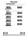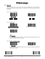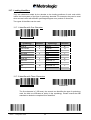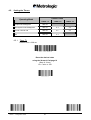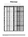
1
IS1000 Series Radio Frequency Bar Code Reader Configuration Guide Metrologic Instruments GmbH Dornierstrasse 2 82178 Puchheim GERMANY Tel. : +49 (0) 89 890 19 0 Fax : +49 (0) 89 890 19 200 Metrologic Instruments GmbH makes no guaranteed declaration or offer concerning the contents or use of this manual, and notably refutes any express or implicit liability as regards the merchandisable quality or suitability for a particular use of the product. In addition, Metrologic Instruments GmbH reserves the right to update this publication and to make changes at any time without notice. Metrologic Instruments GmbH refutes any liability concerning any modifications that might be made to the commodities supplied. You use this equipment at your own risks and perils. Metrologic Instruments GmbH will not be held liable for any direct or indirect losses or damage resulting from its use. Moreover, Metrologic Instruments GmbH reserves the right to modify its products, entirely or in part, at any time without notice. This hardware is guaranteed by Metrologic Instruments GmbH for one year from the date of delivery. During this period, any defective equipment item will be repaired or replaced without charge. Copyright 2001 Metrologic Instruments GmbH. All rights reserved. This manual is intended for the private use of the recipient, whether supplied on paper or in electronic form. It may not be modified or copied by any means whatsoever without written authorization from Metrologic Instruments GmbH. All names of products mentioned in this documentation are registered trademarks of their respective manufacturers. MLPN XX-XXXXX January 2002 IS1000 – Configuration Guide i Metrologic Instruments GmbH Donierstrasse 2 82178 Puchheim GERMANY Tel.: +49 (0)89 890 190 Fax: +49 (0)89 890 19 200 [email protected] Metrologic Instruments Italia S.r.L. Via Emilia 70 40064 Ozzano Dell'Emilia (BO) ITALY Tel.: +39 051 651 19 78 Fax: +39 051 652 13 37 Metrologic Eria Ibérica S.A. Julian Camarillo 29, D1 Bajo 28037 Madrid SPAIN Tel.: +34 91 327 24 00 Fax: +34 91 327 38 29 Metrologic Eria Ibérica S.A. Consell de Cent 106 – 108 – 3° 3a 08015 Barcelona SPAIN Tel.: +34 93 423 11 10 Fax: +34 93 423 14 76 Metrologic Eria France S.A. Z.I. Paris Nord II, 69, rue de la Belle Etoile, Bât. E – B.P. 50057 95947 Roissy CDG Cedex FRANCE Tel.: +33 (0)1 48 63 78 78 Fax: +33 (0)1 48 63 24 94 Metrologic Instruments U.K., Ltd. 58 Tempus Business Centre, Kingsclere Road Basingstoke, Hampshire RG21 6XG UNITED KINGDOM Tel.: +44 (0) 1256 365 900 IS1000 – Configuration Guide Fax: +44 (0) 1256 365 955 ii TABLE OF CONTENTS 1. INTRODUCTION............................................................................................................. 1 1.1. Default Configuration (factory setting) .............................................................. 3 2. COMMUNICATION MODES........................................................................................... 5 2.1. RS232.................................................................................................................... 6 2.1.1. Baud Rate.................................................................................................. 6 2.1.2. Data Bits .................................................................................................... 7 2.1.3. Parity.......................................................................................................... 7 2.1.4. Stop Bits .................................................................................................... 7 2.1.5. End of Message Character ........................................................................ 8 2.1.6. Time-Out Between Characters .................................................................. 9 2.1.7. ACK/NAK Protocol................................................................................... 10 2.1.8. XON/XOFF Protocol ................................................................................ 10 2.1.9. RTS/CTS Protocol ................................................................................... 10 2.1.10. PC-Term Mode ........................................................................................ 11 2.2. Keyboard-Wedge ............................................................................................... 12 2.2.1. 2.2.2. 2.2.3. 2.2.4. 2.2.5. End of Message Character ...................................................................... 14 Upper / Lower Case Options ................................................................... 14 Types of Numeric Characters .................................................................. 15 Time-Out Between Characters ................................................................ 15 "WYSE" Time-Out.................................................................................... 16 2.3. P.O.S. (Point Of Sale) Systems......................................................................... 17 2.4. Wand Emulation................................................................................................. 18 2.4.1. Transmission Speed ................................................................................ 18 2.4.2. Bar/Space Polarity ................................................................................... 19 2.4.3. Idle State.................................................................................................. 19 2.5. Laser Emulation................................................................................................. 20 3. SYMBOLOGIES ........................................................................................................... 21 3.1. Symbology Selection ........................................................................................ 22 3.2. Code 39............................................................................................................... 24 3.2.1. 3.2.2. 3.2.3. 3.2.4. 3.2.5. 3.2.6. 3.2.7. 3.2.8. Standard/Full ASCII ................................................................................. 24 Full ASCII Extended ................................................................................ 24 Multiread .................................................................................................. 25 Modulo 43 Check Character .................................................................... 25 Pharmacode or Pharma 32/39................................................................. 26 CIP Code 39 ............................................................................................ 26 Start/Stop................................................................................................. 27 Modulo 43 Algorithm................................................................................ 27 3.3. Interleaved 2/5.................................................................................................... 28 3.3.1. Fixed Length(s) Authorized and Set Upon First Reading(s) .................... 28 3.3.2. Fixed Length(s) Authorized and Set Using the Numeric Pad .................. 29 3.3.3. Variable Lengths Authorized.................................................................... 30 3.4. UPC/EAN............................................................................................................. 31 IS1000 – Configuration Guide iii 3.4.1. 3.4.2. 3.4.3. 3.4.4. 3.4.5. 3.4.6. 3.4.7. 3.4.8. Types of UPC/EAN Authorized................................................................ 31 Transformations....................................................................................... 31 Add-On Options ....................................................................................... 32 Leading Prefixes for P.O.S. Systems ...................................................... 33 Flag Option .............................................................................................. 33 Check Digit Options ................................................................................. 34 Product Code........................................................................................... 34 ISBN Conversion ..................................................................................... 34 3.5. Monarch/Codabar .............................................................................................. 35 3.5.1. Start/Stop................................................................................................. 35 3.5.2. Concatenation.......................................................................................... 35 3.6. Code 128............................................................................................................. 36 3.6.1. Check Character...................................................................................... 36 3.6.2. FNC2 Function......................................................................................... 36 3.7. UCC/EAN 128 ..................................................................................................... 37 3.8. Standard 2/5 ....................................................................................................... 38 3.8.1. Number of Lengths Authorized ................................................................ 38 3.8.2. Start/Stop Types ...................................................................................... 38 3.9. MSI ...................................................................................................................... 39 3.9.1. Variable or Fix Lengths............................................................................ 39 3.9.2. Double Check Digit (Modulo 10).............................................................. 39 3.9.3. Single Check Digit (Modulo 10) ............................................................... 39 3.10. Plessey ............................................................................................................... 40 3.11. Telepen ............................................................................................................... 40 3.12. Code 93............................................................................................................... 40 3.13. Matrix 2/5 ............................................................................................................ 41 3.13.1. Types of Start/Stop .................................................................................. 41 3.13.2. Check Digit .............................................................................................. 41 3.13.3. Fixed or Variable Lengths........................................................................ 41 3.13.4. Setting the Authorized Lengths................................................................ 42 3.14. IATA .................................................................................................................... 43 3.15. BC 412................................................................................................................. 43 3.16. 3W7 ..................................................................................................................... 43 3.17. Leading Identifiers............................................................................................. 44 3.17.1. Identifier with One Character ................................................................... 44 3.17.2. Identifier with Three Characters............................................................... 44 3.18. Decoding Selectivity.......................................................................................... 45 4. OPERATING MODES................................................................................................... 47 4.1. Simple Acknowledgment .................................................................................. 47 4.2. Host System Acknowledgment ........................................................................ 48 4.3. On File / Not On File .......................................................................................... 48 4.3.1. Setting the On File Character .................................................................. 49 4.3.2. Setting the Not On File Character............................................................ 49 4.4. Bell ...................................................................................................................... 50 IS1000 – Configuration Guide iv 4.5. Setting the Timers ............................................................................................. 51 4.5.1. Timer T1 .................................................................................................. 51 4.5.2. Timer T2 .................................................................................................. 52 4.5.3. Timer T3 .................................................................................................. 52 5. EDITING MODE............................................................................................................ 53 6. APPENDIXES ............................................................................................................... 55 6.1. Radio Parameters .............................................................................................. 55 6.1.1. Radio Channel ......................................................................................... 55 6.1.2. Number of Re-transmissions ................................................................... 56 6.2. Adjustment of the Beep Sound ........................................................................ 57 6.2.1. Laser Reader ........................................................................................... 57 6.2.2. Radio Base .............................................................................................. 57 6.3. Preamble / Postamble ....................................................................................... 58 6.3.1. Preamble Character................................................................................. 58 6.3.2. Postamble Character ............................................................................... 58 6.3.3. Clear Buffer.............................................................................................. 58 6.4. Conversion of Characters................................................................................. 59 6.4.1. First Character ......................................................................................... 59 6.4.2. Second Character.................................................................................... 61 6.5. Rolling Buffer Mode........................................................................................... 62 6.6. Transmission of the Full ASCII Character Set ................................................ 63 6.7. Displaying the Firmware Level ......................................................................... 64 6.8. Code 39 Full ASCII Extended Table ................................................................. 65 6.9. Multiread character Table ................................................................................. 67 6.10. Code 39 Full ASCII Table .................................................................................. 70 6.11. Numeric Pad....................................................................................................... 81 6.12. Samples of Bar Codes....................................................................................... 82 IS1000 – Configuration Guide v Page intentionally left blank IS1000 – Configuration Guide vi 1. INTRODUCTION This manual contains information about configuration IS1000 laser reader and decoder present in the radio base. The installation procedures and technical description are described in the IS1000 Installation and User’s Guide. The IS1000 Connection List contains the connection numbers (or ID) and the cable references to be used for Keyboard-Wedge communication on PCs and terminals, for communication with P.O.S. systems and Notebooks. For other types of connections see chapter 2, Communication Modes. IS1000 – Configuration Guide 1 Once the radio base is powered on, each parameter value can be changed simply by scanning, with the laser reader, the codes appearing in this manual with respect to configuration sequence. START OF CONFIGURATION bottom left of each page Chapter 2 COMMUNICATION MODES Page 5 Selection of the communication mode and adjustment of the transmission parameters Chapter 3 SYMBOLOGIES Page 21 Selection and adjustment of options Chapter 4 OPERATING MODES Page 47 Selection of the operating mode and adjustment of options Chapter 5 EDITING MODE Page 53 Adjustment of data formats Chapter 6 APPENDIXES Page 55 Adjustment of data formats END OF CONFIGURATION bottom right of each page ! Note: There is no need to adjust all the parameters. Change only the ones concerning your application. Unchanged parameters will keep their previous value. The parameter values are stored in a non-volatile memory called EEPROM and are saved when the radio base is turned off. IS1000 – Configuration Guide 2 1.1. Default Configuration (factory setting) When shipped from the factory, each IS1000 is configured with default parameter values as follows: Default Configuration Communication Mode RS232 mode: - 9600 bps - Even parity - 7 data bits - 1 stop bit - CR/LF end of message characters Symbology Code 39, Code 128, EAN 128, UPC/EAN, Interleaved 2/5, Monarch/Codabar Radio 433 MHz – Channel 3 Operating Mode - Buzzer High volume Simple acknowledgment mode Timer 1 = 200 ms Timer 2 = 3 s Timer 3 = 2 s Number of re-transmissions = 3 These are the main parameters, please check the sections of this manual which concern your application. The default value of each parameter appears like this: 3 to 5 characters Code 39 FUNCTION X ACTIVATED * The text below the code is framed and ended by the sign * to indicate the default value. At any time, the default values of all the parameters can be set by scanning this code: DEFAULT CONFIGURATION ! Caution: The reading of this code will turn all parameters to their default value. IS1000 – Configuration Guide 3 Page intentionally left blank IS1000 – Configuration Guide 4 2. COMMUNICATION MODES The radio base is equipped with a decoder offering a multi-interface communication port. The default communication mode is RS232 (9600 baud, 7 data bits, parity even, 1 stop bit, end message: CR LF). Other communication modes can be selected by using the following sequence: Read the code Start of Configuration bottom left of each page Select the mode of communication Adjust the transmission parameters Read the code End of Configuration bottom right of each page START OF CONFIGURATION IS1000 – Configuration Guide END OF CONFIGURATION 5 2.1. RS232 Use the codes on this page through to page 11 to activate and adjust the RS232 parameters. RS232 MODE ACTIVATED * 2.1.1. Baud Rate 300 600 1200 2400 4800 9600 * 19200 38400 START OF CONFIGURATION IS1000 – Configuration Guide END OF CONFIGURATION 6 2.1.2. Data Bits 7* 8 EVEN * MARK ODD SPACE 2.1.3. Parity 2.1.4. Stop Bits 2 1* START OF CONFIGURATION IS1000 – Configuration Guide END OF CONFIGURATION 7 2.1.5. End of Message Character One character can be systematically transmitted with each code to indicate the end of message: CR/LF * STX…ETX HT SUITE (MINITEL) NONE LF CR EOT Other characters or complete fields can be added to the message using the Preamble / Postamble function (see appendix 6.3, page 58) or the Editing Mode (see chapter 5, page 53). START OF CONFIGURATION IS1000 – Configuration Guide END OF CONFIGURATION 8 2.1.6. Time-Out Between Characters In case that errors are detected using high speed transmissions such as 19200 or 38400 baud and if two stop bits are already set, a time-out can be inserted between each character for a better synchronization: 0 ms * 10 ms 20 ms 50 ms 100 ms START OF CONFIGURATION IS1000 – Configuration Guide END OF CONFIGURATION 9 2.1.7. ACK/NAK Protocol Once this protocol is activated, the decoder waits for an acknowledgment from the host system: • ACK (06 hexa) means: message correctly received by the host system. • NAK (15 hexa) means: message incorrectly received by the host, upon reception of this character the decoder resends the message. ACK/NAK ACTIVATED ACK/NAK DISACTIVATED * 2.1.8. XON/XOFF Protocol Using this protocol, the host system can control the data flow coming from the decoder: • XON (11 hexa) means: host system ready to receive data. • XOFF (13 hexa) means: host system busy, the decoder stops the transmission and waits for an XON. XON/XOFF ACTIVATED XON/XOFF DISACTIVATED * 2.1.9. RTS/CTS Protocol This protocol is a hardware "handshake" between the decoder and the host system. Before transmitting data, the decoder rises its RTS signal (pin 4) to +10 volt and waits for a +10 volt signal on its CTS (pin 5) from the host. The rest position of the two pins is -10 volt. RTS/CTS PROTOCOL ACTIVATED RTS/CTS PROTOCOL DISACTIVATED * START OF CONFIGURATION IS1000 – Configuration Guide END OF CONFIGURATION 10 2.1.10. PC-Term Mode Some applications use several RS232 terminals connected to a PC host system configured in PC-Term mode. When a character is typed on a keyboard of a terminal, its scan code value is transmitted to the PC instead of its ASCII value. Then, upon reception, the PC sends back the corresponding ASCII character to display on the screen. Therefore, once this mode is activated, the decoder sends the scan code value of each character read. To activate the PC-Term mode, read this code and adjust the RS232 parameters using page 6 to 10. It is advised to insert a time-out of 50 ms between each character when baud rate is over 9600 baud (see page 9). PC-TERM MODE ACTIVATED Upper/lower case characters and the type of numeric characters can be adjusted using page 14 and 15. Keyboard layout style can be selected using the Bar Code Pad page 12, without reading the code Keyboard-Wedge Mode Activated. START OF CONFIGURATION IS1000 – Configuration Guide END OF CONFIGURATION 11 2.2. Keyboard-Wedge In this mode the radio base is connected between the keyboard and the computer (or terminal). Data is emulated by the decoder as if it was typed on the keyboard. The default communication mode (factory setting) is RS232, use the codes on this page to activate the Keyboard-Wedge mode and to select the ID corresponding to your computer or terminal: KEYBOARD-WEDGE MODE ACTIVATED Consult the IS1000 Connection List and enter the ID corresponding to your computer or terminal using this Bar Code Pad 0 1 2 3 4 5 6 7 8 9 START OF CONFIGURATION IS1000 – Configuration Guide END OF CONFIGURATION 12 PC Keyboard-Wedge ID: PC Keyboard Type ! ID ALT Mode 114 Belgian 644 French 1 German 104 Hungarian 437 Italian 123 Spanish 313 Swedish 169 Swiss 148 UK 611 US 11 Note: For other Keyboard-Wedge interfaces, please refer to the IS1000 Connection List to obtain ID and cable reference. START OF CONFIGURATION IS1000 – Configuration Guide END OF CONFIGURATION 13 2.2.1. End of Message Character One of the characters below can be systematically emulated by the decoder as the end of message character: RETURN * FIELD EXIT ENTER TAB + CR/LF ; FEED ; SEND LF FIELD ADVANCE NO CHARACTER Other characters, signs, function keys or fields can be added using the Preamble / Postamble function (see appendix 6.3, page 58) or the Editing Mode (see chapter 5, page 53). 2.2.2. Upper / Lower Case Options Use one of these codes to inform the decoder of the state of your keyboard: LOWER CASE/SMALL UPPER CASE/CAPS * START OF CONFIGURATION IS1000 – Configuration Guide END OF CONFIGURATION 14 2.2.3. Types of Numeric Characters This function allows the emulation of the numeric characters of the numeric pad or those located on top of the keyboard. Use this function if trouble occurs with upper/lower case keyboard modes. NUMERIC PAD NUMERICS LOCATED OVER THE ALPHANUMERIC PAD * ! Note: If the option Numeric Pad is chosen, the numeric pad of the keyboard must be also turned on (or locked) for correct operation. 2.2.4. Time-Out Between Characters The insertion of a time-out between each character can sometimes avoid eventual errors due to a fast transmission speed (specially on PS/2 or when DOS and BIOS are very busy). 0 ms * 5 ms 10 ms 20 ms 50 ms 100 ms START OF CONFIGURATION IS1000 – Configuration Guide END OF CONFIGURATION 15 2.2.5. "WYSE" Time-Out Some Keyboard-Wedge connections on some Wyse terminals can drop characters especially when a string of identical characters appears in a code. Only in this case, use this function to insert a time-out between characters: ACCESS CODE TIME-OUT Enter the desired value using the Numeric Pad page 81 0 ≤ value ≤ 49 VALIDATION START OF CONFIGURATION IS1000 – Configuration Guide END OF CONFIGURATION 16 2.3. P.O.S. (Point Of Sale) Systems The main communication modes with P.O.S. systems are: • RS232 • Keyboard-Wedge • OCIA • RS485 To set RS232 communication use pages 6 to 11 to adjust the transmission parameters. To set a Keyboard-Wedge, OCIA or RS485 communication use page 12 of this manual; scan the code Keyboard-Wedge Mode Activated and enter your ID. ! Note: Please refer to the IS1000 Connection List to obtain ID and cable reference. START OF CONFIGURATION IS1000 – Configuration Guide END OF CONFIGURATION 17 2.4. Wand Emulation Scan this code to activate the wand emulation mode: WAND EMULATION MODE ACTIVATED Then select the symbology to be emulated using the Bar Code Pad page 12, without reading the code Keyboard-Wedge Mode Activated: Emulation ID Code 39 69 Interleaved 2/5 68 UPC/EAN * 70 * Only 8 or 13 characters messages are accepted for this emulation Then adjust the following transmission parameters. 2.4.1. Transmission Speed HIGH * MEDIUM LOW START OF CONFIGURATION IS1000 – Configuration Guide END OF CONFIGURATION 18 2.4.2. Bar/Space Polarity BAR = 0, SPACE = 1 BAR = 1, SPACE = 0 * 2.4.3. Idle State LOW (0 VOLT) HIGH (5 VOLT) * START OF CONFIGURATION IS1000 – Configuration Guide END OF CONFIGURATION 19 2.5. Laser Emulation With this mode, data are transmitted as code 39 data coming from a TTL hand held laser or CCD scanner. Scan this code to activate this mode: LASER EMULATION MODE ACTIVATED ! Note: For the radio base connector pin-out, refer to the IS1000 Installation and User’s Guide. START OF CONFIGURATION IS1000 – Configuration Guide END OF CONFIGURATION 20 3. SYMBOLOGIES Many bar code symbologies have been developed to suit many data capture applications in different domains (retail, industry, medical, transport…) requiring simple or complete sets of characters (numeric, alphanumeric, full ASCII set…) with various density performances. Each symbology has options which must be carefully checked and adjusted by the user. Some samples are printed in appendix 6.12, page 82. The default configuration of the IS1000 permits the reading of only six bar code symbologies appearing on the next left hand page. Other symbologies can be selected on the next right hand page by using the following sequence: Read the code Start of Configuration bottom left of each page Read the code New Selection Select the new group of bar code symbologies desired Adjust the options of each bar code symbology desired Read the code End of Configuration bottom right of each page To fully optimize the decoding reliability, it is advised to select only the symbology(ies) required for your application. In addition, a function called Decoding Selectivity (see page 45) will perform several data collections and decodings with comparisons before transmission. START OF CONFIGURATION IS1000 – Configuration Guide END OF CONFIGURATION 21 3.1. Symbology Selection NEW SELECTION This code must be read to initialize any new selection of symbologies CODE 39 * INTERLEAVED 2/5 * UPC/EAN * MONARCH/CODABAR * CODE 128 * EAN 128 * These six bar code symbologies are the most commonly used and are active by default. Other symbologies can be selected on the next page. ! Note: • If no symbology is selected after the reading of New Selection code, the above six symbologies will remain activated. • Only the symbologies selected after the reading of New Selection code will be activated • If New Selection code is not read before selecting another symbology, this will be added to the six of above. START OF CONFIGURATION IS1000 – Configuration Guide END OF CONFIGURATION 22 STANDARD 2/5 MSI PLESSEY TELEPEN CODE 93 MATRIX 2/5 IATA BC 412 ** 3W7 Reserved # 1 Reserved # 2 Reserved # 3 Once your selection is completed, consult the next pages to verify and adjust the options you require for each symbology. ** Strictly reserved for IBM and authorized companies; require a specific firmware. START OF CONFIGURATION IS1000 – Configuration Guide END OF CONFIGURATION 23 3.2. Code 39 This is the most popular alpha-numeric bar code symbology. It has a set of 43 characters (alphanumeric and a few symbols) and can be used with or without a check digit. 3.2.1. Standard/Full ASCII The Code 39 Full ASCII option allows the transmission of the 128 ASCII characters. Each ASCII character is a combination of two Code 39 characters. It can be very useful specially to transmit control characters (STX, ETX, TAB, EOT…) as preambles or postambles in a message (see appendix 6.3, page 58). The Code 39 Full ASCII Table is listed in appendix 6.10, page 70. FULL ASCII STANDARD * 3.2.2. Full ASCII Extended In Keyboard-Wedge mode, function keys like F1 to F12, t, HOME, CLEAR… can be emulated using this function. The function key to be emulated is represented by two Code 39 characters from the Code 39 Full ASCII Extended Table (see appendix 6.8, page 65), which can be part of the symbol or separate from it. DISACTIVATED * ACTIVE ON TWO CHARACTERS PRECEDED BY A DASH (part of or separate from the symbol) ACTIVE ON TWO CHARACTERS (part of or separate from the symbol) ACTIVE ONLY ON TWO CHARACTERS SEPARATE FROM THE SYMBOL ! Note: The function key value to be emulated can be set as a preamble or a postamble of message (see appendix 6.3, page 58). START OF CONFIGURATION IS1000 – Configuration Guide END OF CONFIGURATION 24 3.2.3. Multiread ACTIVATED DISACTIVATED * The Multiread function permits the temporary storage of one or more codes in the decoder's memory which will then be transmitted in a single string message. To operate the Multiread function, the desired group of codes to be first stored must have a Multiread Character as the leading character. This character can be chosen in the Multiread Character Table (see appendix 6.9, page 67; default is SPACE character) after reading code Activated. The transmission will start once a code having no Multiread Character is read. 3.2.4. Modulo 43 Check Character In the case of high level security applications, a check character can be integrated as the last character in the code and verified before transmission. VERIFIED AND TRANSMITTED NOT VERIFIED * VERIFIED AND NOT TRANSMITTED ! Note: See page 27 for the calculation algorithm of Code 39 Modulo 43 Check Character. START OF CONFIGURATION IS1000 – Configuration Guide END OF CONFIGURATION 25 3.2.5. Pharmacode or Pharma 32/39 This symbology is used only in Italy. The encoding uses the Code 39 standard but the decoding performs a transformation of the digits using a translation table. Example: The Code 39 message: 2 D W W K P will be transformed into 080638517. To activate this symbology, the code New Selection must be read first. NEW SELECTION * PHARMACODE ACTIVATED START/STOP NOT TRANSMITTED * START/STOP TRANSMITTED CHECK DIGIT TRANSMITTED * CHECK DIGIT NOT TRANSMITTED 3.2.6. CIP Code 39 CIP Code is specific to the French pharmaceutical industry. This function allows the reading of the CIP Code 39 only (code with 7 characters), with the possibility of transmitting or not the check digit. To cancel this function, read the code All Codes 39. ACTIVATED WITH CHECK DIGIT NOT TRANSMITTED ACTIVATED WITH CHECK DIGIT TRANSMITTED ALL CODES 39 * START OF CONFIGURATION IS1000 – Configuration Guide END OF CONFIGURATION 26 3.2.7. Start/Stop This function activates the transmission of the start and stop characters (sign ¸). TRANSMITTED NOT TRANSMITTED * 3.2.8. Modulo 43 Algorithm Code 39 is strongly self checked and most situations do not require a check character. If a specific application requires exceptional data security, a check character can be added as the last character of the code. Example: Message: 12345/ABCDE Sum of values: 1 + 2 + 3 + 4 + 5 + 40 + 10 + 11 + 12 + 13 + 14 = 115 Divide 115 by 43. The quotient is 2 with the remainder 29. The check character is the character corresponding to the value of the remainder, which is 29 in this example, corresponding to the character T. The complete message, including check character is: 12345/ABCDET. Numerical value assignments for computing the optional check character: Character Value Character Value Character Value 0 0 F 15 U 30 1 1 G 16 V 31 2 2 H 17 W 32 3 3 I 18 X 33 4 4 J 19 Y 34 5 5 K 20 Z 35 6 6 L 21 - 36 7 7 M 22 . 37 8 8 N 23 Space 38 9 9 O 24 $ 39 A 10 P 25 / 40 B 11 Q 26 + 41 C 12 R 27 % 42 D 13 S 28 E 14 T 29 START OF CONFIGURATION IS1000 – Configuration Guide END OF CONFIGURATION 27 3.3. Interleaved 2/5 This symbology is only numeric and offers a very high density of characters per inch due to its interleaved encoding system. The decoding is very easy even if the symbols are poorly printed. These advantages make it very popular for industrial applications. But to avoid missing characters when scanning is incomplete, it has to be used with fixed lengths (see pages 28 or 29) or variable lengths with a check digit (see page 30). 3.3.1. Fixed Length(s) Authorized and Set Upon First Reading(s) The characters are interleaved (always paired), therefore it is necessary to define whether the number of significant characters is odd or even. EVEN * ODD 1 LENGTH FIXED AFTER THE FIRST READ * 2 LENGTHS FIXED AFTER THE FIRST 2 READS 3 LENGTHS FIXED AFTER THE FIRST 3 READS 4 LENGTHS FIXED AFTER THE FIRST 4 READS ! Note: In this mode, the code lengths are not saved after power-off. START OF CONFIGURATION IS1000 – Configuration Guide END OF CONFIGURATION 28 3.3.2. Fixed Length(s) Authorized and Set Using the Numeric Pad Select the number of code length(s) desired (1 to 4): ONE TWO THREE FOUR Select the N° of the length to be adjusted: LENGTH N° 1 LENGTH N° 2 LENGTH N° 3 LENGTH N° 4 Enter the desired number of characters using the Numeric Pad page 81 VALIDATION Go back to adjust a next N° of length or read the code End of Configuration if no other lengths is desired. ! Note: In this mode, the code lengths are saved after power-off. START OF CONFIGURATION IS1000 – Configuration Guide END OF CONFIGURATION 29 3.3.3. Variable Lengths Authorized ACTIVATED CHECK DIGIT VERIFIED BUT NOT TRANSMITTED CHECK DIGIT VERIFIED AND TRANSMITTED How to calculate the check digit value: Example: Message: 14356 Add the odd positions: 1 + 3 + 6 = 10 Multiply by 3 = 30 Add the even positions. 30 + 4 + 5 = 39 The check digit is the complement to the next ten: CK = 40 – 39 = 1 The printed message will be: 143561 CIP CHECK DIGIT VERIFIED BUT NOT TRANSMITTED CIP CHECK DIGIT VERIFIED AND TRANSMITTED CHECK DIGIT NOT VERIFIED * ! Caution: The mode Check Digit Not Verified is not advised, missing characters can occur in case of incomplete scanning of a code. START OF CONFIGURATION IS1000 – Configuration Guide END OF CONFIGURATION 30 3.4. UPC/EAN This symbology is mainly used for retail applications. It has fixed lengths (8 or 12 characters for UPC, 8 or 13 characters for EAN) and uses a check digit as the last character and is only numeric. Two or five supplemental digits called Add-On can be added to the right hand size of the codes. 3.4.1. Types of UPC/EAN Authorized ALL UPC/EAN CODES * EAN 13 AUTHORIZED UPC A AUTHORIZED EAN 8 AUTHORIZED UPC E AUTHORIZED ! Note: Several selections can be accumulated. 3.4.2. Transformations UPC TRANSMITTED AS EAN * UPC TRANSMITTED AS UPC UPC E TRANSMITTED AS UPC E * UPC E TRANSMITTED AS UPC A START OF CONFIGURATION IS1000 – Configuration Guide END OF CONFIGURATION 31 3.4.3. Add-On Options The Add-On is a group of 2 or 5 digits printed on the right hand size of a code which can be transmitted or not depending of the following settings: ADD-ON TRANSMITTED ADD-ON NOT TRANSMITTED * If Add-On Transmitted is set, some conditions can be fixed: ADD-ON MUST BE PRESENT ADD-ON MAY NOT BE PRESENT * If Add-On Must Be Present is selected, other conditions can be fixed: On the type of Add-On accepted: WITH 2 OR 5 CHARACTERS * WITH 5 CHARACTERS ONLY WITH 2 CHARACTERS ONLY For specific applications with EAN 13 on magazines: Code EAN 13 starting with the 3 digits 378 or 379 will be decoded only if the AddOn is available and correctly decoded. ACTIVATED DISACTIVATED * START OF CONFIGURATION IS1000 – Configuration Guide END OF CONFIGURATION 32 3.4.4. Leading Prefixes for P.O.S. Systems Leading characters can be transmitted with each code to inform the P.O.S. system with the type of UPC or EAN read. The prefixes are: FF for EAN 8, F for EAN 13, A for UPC A, E for UPC E. PREFIXES TRANSMITTED PREFIXES NOT TRANSMITTED * 3.4.5. Flag Option The Flag is the first digit of the code. It can be transmitted or suppressed. EAN 13 FLAG TRANSMITTED * EAN 13 FLAG NOT TRANSMITTED EAN 8 FLAG TRANSMITTED * EAN 8 FLAG NOT TRANSMITTED UPC A FLAG TRANSMITTED * UPC A FLAG NOT TRANSMITTED UPC E FLAG TRANSMITTED * UPC E FLAG NOT TRANSMITTED START OF CONFIGURATION IS1000 – Configuration Guide END OF CONFIGURATION 33 3.4.6. Check Digit Options EAN 13 CHECK DIGIT TRANSMITTED * EAN 13 CHECK DIGIT NOT TRANSMITTED EAN 8 CHECK DIGIT TRANSMITTED * EAN 8 CHECK DIGIT NOT TRANSMITTED UPC A CHECK DIGIT TRANSMITTED * UPC A CHECK DIGIT NOT TRANSMITTED UPC E CHECK DIGIT TRANSMITTED * UPC E CHECK DIGIT NOT TRANSMITTED 3.4.7. Product Code The product code is represented by the last six digits (without the check digit) can be transmitted alone: PRODUCT CODE ONLY ALL CHARACTERS TRANSMITTED * 3.4.8. ISBN Conversion This function converts UPC/EAN codes appearing on book into ISBN format. The 3 leading digits and the check digit of UPC/EAN codes are suppressed and the remaining 9 digits are transmitted with the ISBN check digit calculated by the decoder. UPC/EAN CONVERTED IN ISBN UPC/EAN TRANSMITTED AS AN UPC/EAN * START OF CONFIGURATION IS1000 – Configuration Guide END OF CONFIGURATION 34 3.5. Monarch/Codabar The Codabar (or Monarch) is a very high reliable bar code which has been designed specially for medical applications such as blood bag identification. Its character set contains numerics and four symbols. 3.5.1. Start/Stop NOT TRANSMITTED * TRANSMITTED a b c d Small * ABCD BLOCK a, b, c, d are the different start/stop characters. 3.5.2. Concatenation STANDARD CONCATENATED * This function permits the capture of two codes with only one scan. Codes must be close to one another and on the same "line". Once captured, the two codes are assembled and transmitted as one message. ! Note: To operate this function correctly, the first code must end with the "d" stop character and the second code must start with the "d" start character. These two start/stop characters are cleared before transmission. START OF CONFIGURATION IS1000 – Configuration Guide END OF CONFIGURATION 35 3.6. Code 128 This symbology offers a great flexibility with its three sets of characters: • Set A: upper case alphanumeric characters and all ASCII control characters. • Set B: upper and lower case alphanumeric characters and some symbols. • Set C: numeric only but which a very high density of characters per inch. Good quality printed codes are recommended due to the continuous structure (no gaps between characters) and the four types of bar and space widths. It works with a modulo 103 check character as the last character. ! Note: The UCC/EAN 128 options are described on next page. 3.6.1. Check Character NOT VERIFIED BUT TRANSMITTED VERIFIED BUT NOT TRANSMITTED * VERIFIED AND TRANSMITTED 3.6.2. FNC2 Function This function permits the temporary storage of a code in the decoder if this code starts with the FNC2 character. The message buffered will be concatenated and transmitted with next code having no FNC2 character. FNC2 ACTIVATED FNC2 NOT ACTIVATED * START OF CONFIGURATION IS1000 – Configuration Guide END OF CONFIGURATION 36 3.7. UCC/EAN 128 This symbology is fully compatible with Code 128. The main difference between EAN 128 and conventional Code 128 is that EAN 128 codes always contain a reserved non-data character, function 1 (FNC1), as the first character after the start character. This FNC1 character acts also as a separator of fields in the code. Example of code UCC/EAN 128 structure: START FNC1 ID – DATA 1 FNC1 ID – DATA 2 CK STOP START : Start character from set A, B or C FNC1 : Separator character ID : Identifier of type of data CK : Check digit modulo 103 STOP : Stop character The decoder detects an UCC/EAN 128 code when FNC1 is the leading character. The transmission of the data string will be performed as follow: ] C1 ID – DATA 1 GS ID – DATA 2 ] C1 : Three characters representing the identifier of the code UCC/EAN 128 GS : ASCII character (1D hexa) acting as a separator ! Note: In Keyboard-Wedge mode, the character GS is transmitted as quotes " (22 hexa). The character FNC1 can be transmitted or not using these codes: FNC1 TRANSMITTED FNC1 NOT TRANSMITTED * START OF CONFIGURATION IS1000 – Configuration Guide END OF CONFIGURATION 37 3.8. Standard 2/5 This symbology is numeric only and uses the same encoding system as the code Interleaved 2/5 but only the bars are significant. The problem of reliability is also the same in case of incomplete scanning of a code so it has to be used with fix length(s). 3.8.1. Number of Lengths Authorized TWO ONE * To fix the number of characters per length, read one (or two) bar code label(s) having the desired length(s) after the decoder is turned on. ! Note: The length(s) are not saved after power-off. 3.8.2. Start/Stop Types Two types of start/stop characters can be used, select the one corresponding to your application: WITH 2 BARS WITH 3 BARS * START STOP START START OF CONFIGURATION IS1000 – Configuration Guide STOP END OF CONFIGURATION 38 3.9. MSI This symbology is mainly used in libraries to trace the loan of books. It is only numeric and due to its very simple encoding system it can be used only with fixed length or with variable lengths when including one or two check digits. 3.9.1. Variable or Fix Lengths ONE FIXED LENGTH SET BY READING A LABEL AFTER POWER-ON VARIABLE LENGTHS * ! Note: The length is not saved after power-off. 3.9.2. Double Check Digit (Modulo 10) VERIFIED BUT NOT TRANSMITTED * VERIFIED AND BOTH TRANSMITTED BOTH VERIFIED BUT ONLY FIRST ONE TRANSMITTED NOT VERIFIED 3.9.3. Single Check Digit (Modulo 10) VERIFIED AND TRANSMITTED VERIFIED BUT NOT TRANSMITTED START OF CONFIGURATION IS1000 – Configuration Guide END OF CONFIGURATION 39 3.10. Plessey This was the first bar code symbology invented in the UK during the early 70's to control the loan of library books. The character set is numeric and its encoding system is very simple (thin bar = 0, large bar = 1). It can be only read with two check digits as last characters. CHECK DIGIT NOT TRANSMITTED CHECK DIGIT TRANSMITTED * 3.11. Telepen Mainly used in UK, this symbology has two separated sets of characters; one is numeric and the other is alphanumeric. Use the codes below to activate the set desired. NUMERIC ALPHANUMERIC * 3.12. Code 93 The 128 ASCII characters can be encoded using this symbology which is more dense than Code 39. Two check digits are always encoded as the last characters and are verified by the decoder but not transmitted. Its Multiread function permits the concatenation of codes in the decoder for those that start with a space character. These will be transmitted upon the reading of a code having no leading space character. MULTIREAD NOT ACTIVATED MULTIREAD ACTIVATED * START OF CONFIGURATION IS1000 – Configuration Guide END OF CONFIGURATION 40 3.13. Matrix 2/5 This is a numeric and a more dense code than the Standard 2/5. Each character is encoded with three bars and two spaces. It is advised to use it with fixed lengths or with a check digit. 3.13.1. Types of Start/Stop WITH 2 BARS WITH 3 BARS * START STOP START STOP 3.13.2. Check Digit VERIFIED BUT NOT TRANSMITTED VERIFIED AND TRANSMITTED * NOT VERIFIED ! Caution: The mode Check Digit Not Verified is not advised, missing characters can occur in case of incomplete scanning of a code. 3.13.3. Fixed or Variable Lengths FIXED VARIABLE * In case that fixed lengths have been set, go to next page to adjust the number of characters per length. START OF CONFIGURATION IS1000 – Configuration Guide END OF CONFIGURATION 41 3.13.4. Setting the Authorized Lengths FIRST LENGTH SELECTED ACCESS CODE FIRST LENGTH Enter the desired number of characters using the Numeric Pad page 81 VALIDATION SECOND LENGTH SELECTED ACCESS CODE SECOND LENGTH Enter the desired number of characters using the Numeric Pad page 81 VALIDATION START OF CONFIGURATION IS1000 – Configuration Guide END OF CONFIGURATION 42 3.14. IATA This code is used by the airline and railway companies and are printed at the bottom of each ticket. It is in fact a Standard 2/5 code with 2 bar start/stop characters. Once activated (see Symbology Selection, chapter 3.1), only codes with 15, 17, 19 or 21 characters can be decoded. 3.15. BC 412 This symbology has been developed by IBM and is reserved for IBM and authorized companies only. To decode it the decoder must be equipped with specific firmware available on request, accompanied with an authorization letter from IBM. It uses a check digit being the second character in the code which is verified and transmitted or not depending of the option selected. CHECK DIGIT TRANSMITTED CHECK DIGIT NOT TRANSMITTED * 3.16. 3W7 Mainly used in Italy, this symbology has a set of 28 characters (numeric, letters A to F, a few symbols and ASCII control characters). A check digit modulo 28 is used as the last character in the code which is always verified but not transmitted. START OF CONFIGURATION IS1000 – Configuration Guide END OF CONFIGURATION 43 3.17. Leading Identifiers They are characters added by the decoder to the leading positions of each code which inform the host system of the type of symbology decoded. For example, they can be used when several codes with different symbologies appear on a product or document. Two types of identifiers can be used: 3.17.1. Identifier with One Character TRANSMITTED NOT TRANSMITTED * Symbology Identifier Symbology Identifier Code 39 A Telepen B Pharmacode S Code 93 G Interleaved 2/5 I Matrix 2/5 Q UPC/EAN E IATA T Monarch/Codabar F BC 412 U Code 128 C 3W7 X EAN 128 J Reserved # 1 V Standard 2/5 R Reserved # 2 W MSI M Reserved # 3 Y Plessey P 3.17.2. Identifier with Three Characters TRANSMITTED NOT TRANSMITTED * The first character is ] (5D hexa), the second one identifies the type of symbology read, the third one indicates an option in the symbology. Please consult the AIM standard to obtain the complete list of identifiers. START OF CONFIGURATION IS1000 – Configuration Guide END OF CONFIGURATION 44 3.18. Decoding Selectivity This function can be used to fully optimize the reliability of decoding when poor printed codes are used. Once activated, the decoder performs three data captures and three decodes then compares them before transmission. MAXIMUM SELECTIVITY (3 captures, 3 decodes) MINIMUM SELECTIVITY * (one capture, one decode) START OF CONFIGURATION IS1000 – Configuration Guide END OF CONFIGURATION 45 Page intentionally left blank START OF CONFIGURATION IS1000 – Configuration Guide END OF CONFIGURATION 46 4. OPERATING MODES The default operating mode of the IS1000 is the "Simple Acknowledgment". Other operating modes can be selected by using the following sequence: Read the code Start of Configuration bottom left of each page Select the desired operating mode Adjust the timers value Read the code End of Configuration bottom right of each page 4.1. Simple Acknowledgment SIMPLE ACKNOWLEDGMENT * • Timer T1 = 200 ms (default value). To configure it, see page 51. START OF CONFIGURATION IS1000 – Configuration Guide END OF CONFIGURATION 47 4.2. Host System Acknowledgment HOST SYSTEM ACKNOWLEDGMENT ACK/NAK PROTOCOL ACTIVATED • Timer T1 = 200 ms (default value). To configure it, see page 51. • Timer T2 = 3 s (default value). To configure it, see page 52. • Timer T3 = 2 s (default value). To configure it, see page 52. 4.3. On File / Not On File ACTIVATED DISACTIVATED ON FILE / NOT ONFILE • Timer T1 = 200 ms (default value). To configure it, see page 51. • Timer T2 = 3 s (default value). To configure it, see page 52. • Timer T3 = 2 s (default value). To configure it, see page 52. START OF CONFIGURATION IS1000 – Configuration Guide END OF CONFIGURATION 48 4.3.1. Setting the On File Character This function can be used to change the On File Character sends by the host. By default: Character ~ (7E hexa). ACCESS CODE ON FILE CHARACTER Enter the desired character using the Code 39 Full ASCII Table page 70 VALIDATION 4.3.2. Setting the Not On File Character This function can be used to change the Not On File Character sends by the host. By default: Character DEL (7F hexa). ACCESS CODE NOT ON FILE CHARACTER Enter the desired character using the Code 39 Full ASCII Table page 70 VALIDATION START OF CONFIGURATION IS1000 – Configuration Guide END OF CONFIGURATION 49 4.4. Bell ACTIVATED DISACTIVATED BELL • Timer T1 = 200 ms (default value). To configure it, see page 51. • Timer T2 = 3 s (default value). To configure it, see page 52. START OF CONFIGURATION IS1000 – Configuration Guide END OF CONFIGURATION 50 4.5. Setting the Timers Operating Mode Default Value Timer T1 Timer T2 Timer T3 Simple Acknowledgment 200 ms Host System Acknowledgment 200 ms 3s 2s On File / Not On File 200 ms 3s 2s Bell 200 ms 3s 4.5.1. Timer T1 Default value = 200 ms ACCESS CODE TIMER T1 Enter the desired value using the Numeric Pad page 81 (Step of 10 ms) 10 ≤ value ≤ 254 VALIDATION START OF CONFIGURATION IS1000 – Configuration Guide END OF CONFIGURATION 51 4.5.2. Timer T2 Default value = 3 s ACCESS CODE TIMER T2 Enter the desired value using the Numeric Pad page 81 (Step of 100 ms) 10 ≤ value ≤ 254 VALIDATION 4.5.3. Timer T3 Default value = 2 s ACCESS CODE TIMER T3 Enter the desired value using the Numeric Pad page 81 (Step of 100 ms) 10 ≤ value ≤ 254 VALIDATION START OF CONFIGURATION IS1000 – Configuration Guide END OF CONFIGURATION 52 5. EDITING MODE START OF CONFIGURATION IS1000 – Configuration Guide END OF CONFIGURATION 53 START OF CONFIGURATION IS1000 – Configuration Guide END OF CONFIGURATION 54 6. APPENDIXES 6.1. Radio Parameters 6.1.1. Radio Channel Channel Number Frequency 1 433.4 MHz 2 433.6 MHz 3 433.8 MHz 4 434.0 MHz 5 434.2 MHz 6 434.4 MHz CHANNEL 1 CHANNEL 2 CHANNEL 3 * CHANNEL 4 CHANNEL 5 CHANNEL 6 START OF CONFIGURATION IS1000 – Configuration Guide END OF CONFIGURATION 55 6.1.2. Number of Re-transmissions Maximum number of bar code re-transmission attempts by the IS1000. 0 1 2 3* 4 5 6 7 START OF CONFIGURATION IS1000 – Configuration Guide END OF CONFIGURATION 56 6.2. Adjustment of the Beep Sound 6.2.1. Laser Reader VOLUME LOW VOLUME HIGH * 6.2.2. Radio Base VOLUME HIGH * VOLUME MEDIUM VOLUME LOW VOLUME OFF DURATION LONG (120 ms) * DURATION MEDIUM (60 ms) DURATION SHORT (20 ms) DURATION VERY SHORT (5 ms) START OF CONFIGURATION IS1000 – Configuration Guide END OF CONFIGURATION 57 6.3. Preamble / Postamble One or several characters (22 maximum) can be systematically added to each message as Preamble (leading positions) or as Postamble (ending positions) before transmission to the host system. These characters can be chosen from the Code 39 Full ASCII Table (see appendix 6.10, page 70) when ASCII characters are required or from the Code 39 Full ASCII Extended Table (see appendix 6.8, page 65) to emulate function keys in Keyboard-Wedge mode. 6.3.1. Preamble Character ACCESS CODE PREAMBLE BUFFER Enter the Preamble character(s) using the Code 39 Full ASCII Table page 70 or the Code 39 Full ASCII Extended Table page 65 6.3.2. Postamble Character ACCESS CODE POSTAMBLE BUFFER Enter the Postamble character(s) using the Code 39 Full ASCII Table page 70 or the Code 39 Full ASCII Extended Table page 65 6.3.3. Clear Buffer To clear a buffer, read the corresponding access code then read the code Clear Buffer Pre-selected. CLEAR BUFFER PRE-SELECTED START OF CONFIGURATION IS1000 – Configuration Guide END OF CONFIGURATION 58 6.4. Conversion of Characters 6.4.1. First Character A first character can be converted into another defined by the user with the codes on this page (see next page for changing a second one). Example: The user wants to convert all Q characters found in an input message into A. Input message Q10Q234 will be changed into output message A10A234. ACCESS CODE FIRST CHARACTER TO BE CONVERTED Enter the desired character using the Code 39 Full ASCII Table page 70 VALIDATION ACCESS CODE NEW CHARACTER DESIRED Enter the desired character using the Code 39 Full ASCII Table page 70 VALIDATION START OF CONFIGURATION IS1000 – Configuration Guide END OF CONFIGURATION 59 Read this code to clear a pre-programmed conversion of a first character. CONVERSION OF FIRST CHARACTER CLEARED START OF CONFIGURATION IS1000 – Configuration Guide END OF CONFIGURATION 60 6.4.2. Second Character ACCESS CODE SECOND CHARACTER TO BE CONVERTED Enter the desired character using the Code 39 Full ASCII Table page 70 VALIDATION ACCESS CODE NEW CHARACTER DESIRED Enter the desired character using the Code 39 Full ASCII Table page 70 VALIDATION Read this code to clear a pre-programmed conversion of a second character. CONVERSION OF SECOND CHARACTER CLEARED START OF CONFIGURATION IS1000 – Configuration Guide END OF CONFIGURATION 61 6.5. Rolling Buffer Mode In this mode, the input data is first stored in the buffer of the decoder (up to 3K characters maximum) and transmitted to the host system at a rhythm fixed by the inter-message timeout selected on this page. It can be useful when the data transmission speed to the host system is slow (specially in Keyboard-Wedge mode) while a group of bar code labels has to be read very quickly (example: carton on a conveyor…) or while a group of RS232 input messages has to be first collected before transmission to the host system. NO TIME-OUT * 100 ms 200 ms 500 ms 700 ms 1 SECOND 1.5 SECONDS 2 SECONDS 3 SECONDS 5 SECONDS 7 SECONDS 10 SECONDS START OF CONFIGURATION IS1000 – Configuration Guide END OF CONFIGURATION 62 6.6. Transmission of the Full ASCII Character Set This function releases the transmission of the 96 printable ASCII characters (20 to 7F hexa) to the host system in any communication mode. The purpose of this function is to verify that all characters are correctly emulated by the decoder specially in Keyboard-Wedge mode. ASCII TABLE TRANSMISSION ACTIVATED START OF CONFIGURATION IS1000 – Configuration Guide END OF CONFIGURATION 63 6.7. Displaying the Firmware Level Once the IS1000 radio base is connected to a host system with communication parameters correctly adjusted, the level of the firmware implemented in the IS1000 laser reader, radio base and its decoder can be displayed. LASER READER AND RADIO BASE The message will appear as follow: Portable=X.XX - - Base=X.XX RADIO BASE DECODER The message will appear as follow: FIRMWARE LEVEL: XXX.XX START OF CONFIGURATION IS1000 – Configuration Guide END OF CONFIGURATION 64 6.8. Code 39 Full ASCII Extended Table ●A ●B FIELD EXIT FIELD ADVANCE ●C ●D ENTER SEND ●E ●F TAB - RETURN ●G ●H RESET, RESTORE HOME ●I ●J t s ●K ●L u v ●M CLEAR IS1000 – Configuration Guide 65 ●N ●O F1 F2 ●P ●Q F3 F4 ●R ●S F5 F6 ●T ●U F7 F8 ●V ●W F9 F10 ●X ●Y F11 F12 ●Z RESERVED IS1000 – Configuration Guide 66 6.9. Multiread character Table SPACE * 0 1 2 3 4 5 6 7 8 9 A B C D E IS1000 – Configuration Guide 67 IS1000 – Configuration Guide F G H I J K L M N O P Q R S T U 68 IS1000 – Configuration Guide V W X Y Z - . * $ / + % 69 6.10. Code 39 Full ASCII Table Translation and values of the bar codes which appear on the next pages. ASCII Code 39 Hexa Value ASCII Code 39 Hexa Value NUL %U 00 SP Space 20 SOH $A 01 ! /A 21 STX $B 02 " /B 22 ETX $C 03 # /C 23 EOT $D 04 $ /D 24 ENQ $E 05 % /E 25 ACK $F 06 & /F 26 BEL $G 07 ' /G 27 BS $H 08 ( /H 28 HT $I 09 ) /I 29 LF $J 0A * /J 2A VT $K 0B + /K 2B FF $L 0C , /L 2C CR $M 0D - - 2D SO $N 0E . . 2E SI $O 0F / /O 2F DLE $P 10 0 0 30 DC1 $Q 11 1 1 31 DC2 $R 12 2 2 32 DC3 $S 13 3 3 33 DC4 $T 14 4 4 34 NAK $U 15 5 5 35 SYN $V 16 6 6 36 ETB $W 17 7 7 37 CAN $X 18 8 8 38 EM $Y 19 9 9 39 SUB $Z 1A : /Z 3A ESC %A 1B ; %F 3B FS %B 1C < %G 3C GS %C 1D = %H 3D RS %D 1E > %I 3E US %E 1F ? %J 3F IS1000 – Configuration Guide 70 Translation and values of the bar codes which appear on the next pages. ASCII Code 39 Hexa Value ASCII Code 39 Hexa Value @ %V 40 ` %W 60 A A 41 a +A 61 B B 42 b +B 62 C C 43 c +C 63 D D 44 d +D 64 E E 45 e +E 65 F F 46 f +F 66 G G 47 g +G 67 H H 48 h +H 68 I I 49 i +I 69 J J 4A j +J 6A K K 4B k +K 6B L L 4C l +L 6C M M 4D m +M 6D N N 4E n +N 6E O O 4F o +O 6F P P 50 p +P 70 Q Q 51 q +Q 71 R R 52 r +R 72 S S 53 s +S 73 T T 54 t +T 74 U U 55 u +U 75 V V 56 v +V 76 W W 57 w +W 77 X X 58 x +X 78 Y Y 59 y +Y 79 Z Z 5A z +Z 7A [ %K 5B { %P 7B \ %L 5C | %Q 7C ] %M 5D } %R 7D ^ %N 5E ~ %S 7E _ %O 5F DEL %T 7F IS1000 – Configuration Guide 71 NUL SOH STX ETX EOT ENQ ACK BEL BS HT LF VT FF CR SO SI IS1000 – Configuration Guide 72 DLE DC1 DC2 DC3 DC4 NAK SYN ETB CAN EM SUB ESC FS GS RS US IS1000 – Configuration Guide 73 SP ! " # $ % & ' ( ) * + , - . / IS1000 – Configuration Guide 74 IS1000 – Configuration Guide 0 1 2 3 4 5 6 7 8 9 : ; < = > ? 75 @ A B C D E F G H I J K L M N O IS1000 – Configuration Guide 76 IS1000 – Configuration Guide P Q R S T U V W X Y Z [ \ ] ^ _ 77 IS1000 – Configuration Guide ` a b c d e f g h i j k l m n o 78 IS1000 – Configuration Guide p q r s t u v w x y z { l } ~ DEL 79 Page intentionally left blank IS1000 – Configuration Guide 80 6.11. Numeric Pad For entering variable data while configuration. IS1000 – Configuration Guide 0 1 2 3 4 5 6 7 8 9 81 6.12. Samples of Bar Codes CODE 39 INTERLEAVED 2/5 CODABAR CODE 128 EAN 128 IS1000 – Configuration Guide 82 UPC E UPC A UPC A with ADD-ON of 5 characters EAN 8 EAN 13 EAN 13 with ADD-ON of 5 characters IS1000 – Configuration Guide 83 Page intentionally left blank IS1000 – Configuration Guide 84