1
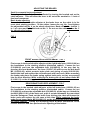
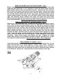
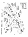
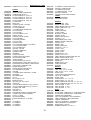
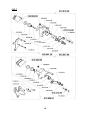
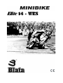
Elite 14 - WRS
Noise emitted by machinery and equipment (Minibike BLATA ELITE 14) - Measurement of emission sound pressure levels at a work
station and at other specified positions. Levels measured by authorized person ( TUV CZ s.r.o.). Test record (no. :
814/90/06/BT/IZ/H) is deposited with producer.
RPM
2600 rpm (idling speed)
11 000 rpm
Average level of the acoustic pressure A at
a work station (ČSN EN ISO 11202)
LAeq = 82,8 dB
LAeq = 106,8 dB
Total average level of the acoustic po
(ČSN EN ISO 3744)
LWA [dB (A)] = 87,2 dB
LWA [dB (A)] = 112,9 dB
SAFETY WARNING
Always pay attention to the instructions and safety warnings below
This manual contains important safety information and instructions which should be read
carefully before operating the vehicle. For your own safety and the safety of others follow
these rules.
Neither manufacturer nor distributor is responsible for injuries caused by unsafe and improper
use of the vehicle.
This vehicle is not allowed to be used on public roads!
Unsafe and careless use of the vehicle can result in serious injuries. The driver can
minimize the potential risks by wearing safety equipment. The driver must wear a
safety helmet, goggles, gloves, elbow pads, kneepads, and firm footwear. Avoid rough
surfaces and obstacles. Always drive with both hands on the handlebars.
Always inspect the bike before each ride (refer to the article ‘INSPECTION AND
MAINTENANCE’). Failure to inspect and maintain your bike properly increases the risk
of an accident or damage to the vehicle.
Fuel and fuel vapour are highly toxic and flamable. Always be careful when handling
fuel – it can burn or poison you.
stop the engine and turn off the fuel tap, keep naked flames and sparks away
from your bike.
do not smoke near your bike.
refuel only outdoors in a well ventilated space
clean up any excess fuel immediately
keep children and pets away
Always ride within the limits of vehicle/ rider and weather conditions to
unnecessary accidents and injuries.
avoid
Check-ups
Shut the engine off when performing maintenance check-ups otherwise You could be
severely injured if your hands or clothing get caught by moving parts.
Make sure the engine and exhaust are cold before performing any inspection of this
machine
Riding with a chain in poor condition or improperly adjusted can lead to serious injury.
Always, Inspect, Adjust and Maintain the drive chain properly before each ride.
Failure to inspect and properly maintain the brakes increases the risk of having an
accident. Before each ride check the brake cables and the brakes efficiency.
Riding with worn brake pads can reduce the braking performance and cause an
accident. Check and replace brake pads according to the instructions in this manual.
Using worn, improperly inflated, or incorrect tyres will reduce stability and can cause
an accident.
DISPOSAL OF UNUSABLE PRODUCT
Unusable product become a waste and it’s desposal should be in accordance with
the law and any applicable local regulations. Don’t throw this product to municipal
waste.
MINIBIKE - ELITE 14 WRS
SERVICE MANUAL FOR USE AND MAINTENANCE AND SPARE PARTS LIST
For your own safety and the safety of others Follow these recommendations in order to use
your MINIBIKE safely and correctly. Read the instructions CAREFULLY, failure to do so may
place yourself and others in extreme and or ultimate DANGER. If you do not understand the
instructions and Data then, you are not to attempt to operate this Minibike under any
circumstances. It may be used for show purposes only!
CONTENTS
PAGE
INTRODUCTION .............................................................................................................. 2
TECHNICAL DATA .......................................................................................................... 2
UNPACKING AND SETTING UP BEFORE RIDING – FIG. 1 ......................................... 3
SAFETY............................................................................................................................ 3
BEFORE STARTING........................................................................................................ 3
STARTING THE ENGINE - FIG. 2 ................................................................................... 4
CARBURETOR - FIG. 3 ................................................................................................... 4
RIDING ............................................................................................................................ 4
PERIODIC MAINTENANCE ............................................................................................. 5
CHAIN SETTING AND MAINTENANCE ......................................................................... 5
CENTRIFUGAL CLUTCH REPAIR OR REPLACEMENT…............................................ 5
BRAKES ADJUSTING - FIG. 4........................................................................................ 6
FRONT BRAKES PADS REPLACEMENT ..................................................................... 6
REAR BRAKES PADS REPLACEMENT
.................................................................... 6
REMOVE AND REFIT THE FRONT WHEEL ............. ……………................................... 7
REMOVE AND REFIT THE REAR WHEEL ............................................................ ....... 7
REPLACEMENT OF SPROCKET - FIG. 9 ..................................................................... 7
ENGINE - BLATA …………………………………………………………………................ 8
MINIBIKE ELITE 14 WRS - FIG. 5 …………………………………………………............... 9,10
PARTS LIST ……………………………………………………………………....................... 11,12
CLUTCH COMPLETE - FIG. 6…………………………………………………..................... 13
FRONT AND REAR BRAKES - FIG. 7 …………………………………………................. 14
REPLACEMENT OF TIRE .............................................................................................. 15
REMOVE AND REFIT AIR FILTER .................................................................................. 15
CLUTCH ADJUSTMENT – FIG. 8 ………………………………………………................... 15
MAINTENANCE OF COOLING SYSTEM ………………………………………................. 16
TORQUE SETTINGS.......................................................................................................... 17
STORAGE PROCEDURES ………………………………………………………….............
18
INTRODUCTION
The Minibike Elite 14 WRS is designed and built for use on a paved closed
circuit track. The track should be clean and without obstacles of any kind.
Qualified adults and younger persons can drive the minibike. Children can
drive the minibike only under the supervision of a responsible adult person.
The minibike is constructed especially for racing competitions on special
racing tracks. Minibike Blata should not be used during winter season and
under bad weather conditions. Usage under these conditions leads to
abnormal mechanical wear and corrosion of most minibike parts - especially
those directly exposed to climatic influences. Beside that, riding under these
conditions increase the risk of injury or health damage.
The minibike uses a single-cylinder two-stroke, Gasoline combustion engine,
and has an air filter and exhaust silencer. Transfer of power to the rear wheel is
through a drive chain. The the overall drive ratio to the rear wheel can be
changed by the replacement of chain sprockets. The front and rear wheel is
equipped with disk brakes. The rear brake is controlled with the left lever and
the front brake is controlled with the right lever on the handlebars.
BASIC TECHNICAL DATA
BLATA…………………………….………………………TWO-STROKE
NUMBER OF CYLINDERS ............................................................... 1
CYLINDER CAPACITY
…………………………….. .........39,8 cc
ENGINE COOLING SYSTEM………………………..LIQUID COOLED
POWER OUTPUT ............................................ 8,6 kW at 11 300 rpm
TORQUE ………………………………..............6,95 Nm at 11 000 rpm
CARBURETOR .............................................. PHVA 14 DELL’ ORTO
FUEL ADMISION …………REED VALVE DIRECT TO CRANKCASE
IGNITION............................................................... CONTACT - LESS
SPARK PLUG…………………….................................... NGK B9EGV
STARTING .......................................... HAND PULL TYPE, MANUAL
CLUTCH .............................................. CENTRIFUGAL AUTOMATIC
WELDED ...........................................HIGH STRESS STEEL TUBES
FRAME:
BRAKES: FRONT WHEEL ......................................................... DISC BRAKES
REAR WHEEL.............................................................DISC BRAKES
WHEELS: FRONT ........................................... OF LIGHT ALLOY 2,1”x 6,5”- 99
REAR ........................................... OF LIGHT ALLOY 2,1”x 6,5”- 130
TIRE:
FRONT .....................................................................SIZE 90/65 - 6,5”
REAR .........................................................110/50 - 6,5”, 90/65 - 6,5”
FUEL:
.........MIXTURE OF PETROL 95 OR HIGHER OCTANE +2 STROKE
SYNTHETIC OIL MIXING RATIO (after break in period) ........ 33 : 1
TANK CAPACITY .....................................................................1 Litre
SPEED:
WITH THE INSTALLED RATIO: .................... up to 50mph( 80km/h)
UNLOADED WEIGHT: .................................................................. (50,6lbs.) 23 kg
CARRYING CAPACITY:.................................................................(240lbs) 110 kg
BASIC DIMENSIONS:
LENGTH .................................................................... 37,7 “ (960 mm)
WIDTH............................................................................ 20” (500mm)
HEIGHT ...................................................................... 21,2” (540 mm)
ENGINE:
2
UNPACKING AND SETTING UP BEFORE RIDING
The minibike is delivered in a cardboard carton and packed with folded
handlebars and brake levers. After unpacking, set up the handlebars into the
position, that suits the best for driving. The maximum pulled brake lever
position should not touch on the handlebar grip. After setting up, tighten the
handlebar bolts 1, brake lever bolts 2, and the throttle assy. Bolts. See, Fig. 1.
The level of foot rest’s can be regulated by loosening the bolt M5 (914.003.01)
on the handle of the foot rest (139.001.01). The foot rest can be moved to the
front or back position. It is recommended to try and check the position of
handlebars and foot rest’s individually. While tightening the bolts and nuts, do
not use an excessive force as to not damage the threads, or distort the tubes
and other parts. Verify the smooth and perfect function of the Bowden cables
to throttle and both brakes. Fill the cooling system with coolant and vent the
system (follow the instructions in chapter MAINTENANCE OF COOLING
SYSTEM). Fill the fuel tank with fuel mixture. Failure to use the proper oil mix
ratio will result in Engine damage for which you will be responsible.
FIG. 1
6
4
2
1
5
Operating controls:
1. Handlebar bolts
2. Brake lever bolts
3. Throttle Assy. bolts
4. Stop switch
5. Front brake lever
6. Rear brake lever
7. Balance tank for coolant
3
7
Range of adjusting handlebars
function position
1
SAFETY
The minibike is unsuitable for public road use. It does not comply with valid
Safety Standards. Unsafe and careless use of a minibike can result in serious
injuries. The driver can minimize the potential risks by wearing the Safety
Equipment. The driver must wear safety helmet, goggles, gloves, elbow pads,
kneepads, and firm footwear. The minibike cannot be used on wet, icy or oily
surfaces. Avoid uneven surfaces and obstacles. Drive with two hands on the
handlebars.
BEFORE STARTING
It is strongly recommended to follow all the instructions about the break-in
period to promote engine reliability and long life. Break-in period of the
minibike is complete after the consumption of five full fuel tanks. It is important
to use mixture of petrol 95 or higher Octane with 2-stroke synthetic oil in the
ratio 30:1 and after break-in period a ratio of 33:1. Mix the petrol and oil
completely before putting it into the fuel tank. During the break-in period do
not run the engine at maximum RPM and do not allow the engine to overheat.
3
Check the tire inflation – 200 kPa (2 bars) or (28 to 30psi) to be commensurate
with the driver’s weight. The Tyre pressure should never exceed 2,5 bars,
(38psi) in either the front or rear wheel.
IMPORTANT NOTICE: If the coolant level rises in the balance tank, switch off
the engine immediately! Check the drive of the coolant pump and sealing of the
cooling system. After these steps, execute the ventilation of the Radiator. The
raised level of coolant is an indicator of a overheated engine, which can result
in seizing the piston in the cylinder.
STARTING THE ENGINE
Engine starting should be done only on the stand - Fig. 2. Fill the fuel tank and
close it with the filler cap. Open the Gas petcock. Set the petrol supply cock.
Set the choke lever into position “C”, Fig. 3. Without turning the accelerating
handle, pull gently twice the starting wire and by next guick pull start the
engine. It is not allowed to pull the starting wire up to full winding off. After
short engine run, set the choke lever back to position “A”. Let the engine run
about 1 min. Leave the minibike on the stand with running engine and if
necessary adjust the revolutions so the rear wheel is not turning. For
adjustment use the adjustment screw No. 3 on the carburetor Fig. 3.
FIG. 2
2
1
C
A
FIG. 3: CARBURETOR
1. Air filter
2. Carburetor body
3. Idle speed adjusting screw
4. Float chamber
3
4
A – Cock position for riding
C – Cock position for cold starting
RIDING
Remove the minibike from the stand to sit on the seat. When seated, then
slowly rotate the throttle grip to start riding. Before braking, rotate the Throttle
grip to the off or idle position and lightly depress the rear brake lever with left
hand and then the front brake lever with right hand. Beware to not skid the
wheels. The minibike engine is switched off by pushing the red button (Engine
stop switch) on the handlebars. It is necessary to check the tightness of bolts
and nuts, especially of the engine, and the brake settings after the first ride and
often during the break in period.
4
PERIODIC MAINTENANCE
Periodic maintenance is the best way to help the machine perform well, give longevity and
provide safety and low cost operation. In addition, you will be spared from many worries from
self caused problems, resulting from poor maintinence or no maintinence.
A - Before every ride:
1. Check the Cables and efficiency of brakes.
2. Check the lubrication and chain tension settings. The chain free play should
be (5 mm) (.200in) After every ride clean the minibike carefully and keep it
clean. Do not use aggressive cleaning detergents.
3. After 1-hour of use, wash the air filter in air drying spirits and lubricate it
with special oil for air filters.
4. After 1- hour of use, check the state of the clutch pads. Review the clutch
adlustment.
B. After every 5 hours of riding:
5.Check the tightness of all bolts and nuts. Tighten with a properly adjusted
torgue wrench only ! For torgue settings see tables on page 17.
6. Wash the air filter in gas and lubricate it with special oil for an air filters to
better catch the dust.
7. Clean carefully the carburetor float chamber.
8. Check the brake pads, the thickness of brake lining cannot be less than 1
mm (.039 in). Review the basic brake adjustment.
9.Check the state of the clutch pads - the thickness cannot be less than 1 mm
(.039in). Review the clutch adjustment.
C - Every time after 10 hours of riding:
10.Check the state of the clutch pads - the thickness cannot be less than 1 mm
(.039in).
CHAIN SETTING AND MAINTENANCE
To set the chain tension, loosen the Nut (920.011.01) of the axel thru the rear
wheel and the nut (914.021.01) of the rear Caliper anchor plate. The required
chain tension (chain free play) is 5 mm (.200in) and is performed by equal
movement of the Axel adjustor plate (920.009.01) on the both sides of the rear
wheel. When the adjustment is correct, tighten the Axel nuts and the Caliper
holding nut. Tighten the adjustor plate nuts both sides an extra nip, just to set
them firmly. It is important to lubricate the chain regularly, to avoid excess
wear and prolong effective lifetime. The lubrication is important after every ride
on a wet surface. It is recommended to lubricate the minibike with special
chain spray. If chain replacement is necessary, check both chain Sprockets
and if there is a need to change them do it together with the chain.
CENTRIFUGAL CLUTCH PARTS, REPLACEMENT
Remove the chain guard by loosing two bolts M6 (916.020.01), Fig. 5. Loosen
the chain and remove it from the sprocket. Next, loosen three bolts holding the
aluminum clutch housing. Remove it together with steel clutch basket, and
dismantle it. Loosen the bolt from the carrier and remove the clutch from the
engine. Loosen and remove the adjustable bolts and springs. Then dismantle
the safety rings from pins. When all this is done, replace with new clutch
slipper shoes and springs (if required), at this time. During the reassembly
process follow these steps: 1. put the plate with the springs on the slipper
shoes. 2. Put the plate against the carrier and mount it on the fixed pins.
Fit it with the safety rings and install the adjustable bolts.
5
ADJUSTING THE BRAKES
Small incremental brake adjustment
Free play at the handlebar lever is effected by turning the knurled end on the
cable adjustor. This will allow the lever to be set at the nominal to ¼ inch of
free lever movement.
Basic brake adjusting:
Screw in the knurled cable adjustor at the brake lever so the cable is in it’s
most slack starting position.. At the caliper, loosen the nut, No. 3 and tighten
the adjustable bolt No. 4, so the wheel cannot turn. Back off bolt No. 4 about ¼
to ½ of a turn and fix it with lock nut No. 3. Do not use the cable retainer No. 5
for adjusting the brakes!
5
FIG. 4
3
4
FRONT BRAKE PADS REPLACEMENT - FIG. 7
First screw in the knurled cable adjustor at the right brake lever (122.002.00) on
the handlebars to the starting position (slackened cabled). Loosen the nut
(332.020.00) and turn the adjustable bolt (916.065.02) in the way that by
pressing the front brake lever, the lever (312.017.00) will be over the bolt head
M5 (312.018.00), which protects brake pads and spring of pads (312.020.00).
Unbolt this bolt and replace the old brake pads with new ones. When mounting
the brake pads place the brake spring against both pads, so they are pressed
into the front direction. While replacing the brake pads do not loosen bolts M5
(914.001.01) on the driving pins and do not loosen the cable retainer!
REAR BRAKE PADS REPLACEMENT - FIG. 7
First screw in the knurled cable adjustor at the left brake lever (122.001.00) on
the handlebars to the starting position (slackended cable). Loosen the nut
(332.020.00) and turn the adjustable bolt (916.065.02) all the way out. Unbolt the
nut M10 (920.011.01) of the back axel, push it out and dismantle the rear wheel
from the Swingarm. Push out the brake from driving pins, that will loosen the
brake pads and replace the old ones at this time. While replacing the brake
pads do not loosen bolts M5 (914.001.01) on the driving pins and do not loosen
the cable retainer! During the mounting follow all these instructions in the
reverse direction and then perform basic adjusting of the brakes.
6
REMOVE AND REPLACE THE FRONT WHEEL - FIG. 5
Before dismantling the front wheel it is necessary to remove the front brake
pads from the front brake, so it is possible to move the brake caliper from the
wheel and be able to draw out the wheel and tire. Remove the front axel nut.
M10 (920.011.01) Draw out the axel from the fork and wheel. Remove the wheel
by an easy pull downwards from the forks. Caution, while removing the wheel
the left side spacer washer will fall out! During the assembly process put the
spacer washer between the brake rotor and brake caliper mount plate and the
right side distance spacer between the wheel and right fork (315.011.00).
Return the brake pads with the spring and tighten up the axel nut. Perform the
basic brake adjusting. Double check your work. This is important!
REMOVE AND REPLACE THE REAR WHEEL - FIG. 5
Remove the rear wheel axel nut. Loosen the nut on the rear caliper anchor
plate. Remove the two wheel adjustor plate nuts. (M6) Move the wheel forward
and remove the chain. Safely (hold) keep the rear wheel from falling out while
pulling out the axel. Caution, note the location of both spacer tubes and one
spacer washer (between caliper mount plate and rotor) while removing wheel.
When refitting the wheel, make sure to slide the brake rotor into the caliper
between the pads. Hold the wheel in place and fit the wheel spacers in proper
order. Insert the spacer washer between the caliper plate and the brake rotor
and on the both sides place the axel spacers at the appropiate time during
assembly. Adjust chain tension and tighten axel nut. Tighten the caliper
holder plate nut and set and tighten both chain adjustor plate M6 nuts. At this
time check the brake operation. Recheck all your work. This is important!
REPLACEMENT OF PINION - FIG. 9
First dismantle the front chain guard and chain guard.Loosen the nut of rear
wheel axle and the nut of chain tightener ,remove chain. Insert carefully a
larger screw drive or steel rod into the hole of clutch drum, Fig. 9, to avoid a
turning over the clutch drum at releasing the pinion. Using the pinion wrench
P/ N 319.050.00, release the new pinion to be carried out by reverse way.
FIG. 9
7
FIG. 10
8
9
10
MINIBIKE ELITE 14 WRS
350.000.50
MINIBIKE ELITE 14 WRS
120.041.00
310.040.00
330.002.00
330.004.40
330.004.41
330.004.42
330.004.43
330.005.00
330.008.00
330.010.00
330.011.20
330.015.00
330.016.00
330.017.20
330.018.20
330.021.00
330.022.00
330.023.00
330.024.20
330.025.00
330.028.20
330.029.00
330.030.20
330.031.20
330.032.20
330.039.00
330.040.00
330.045.00
330.046.00
330.047.00
330.049.00
330.051.00
330.052.00
330.053.20
330.056.20
330.058.20
330.059.01
330.065.30
330.066.01
330.067.00
330.068.00
330.073.42
330.076.00
330.077.00
330.080.72
330.083.01
330.085.20
330.089.00
330.120.00
330.140.00
330.141.00
330.150.00
330.151.00
330.152.00
330.153.00
330.155.01
330.159.01
330.165.20
350.001.20
350.063.00
350.069.20
350.069.21
350.069.22
350.069.23
ENGINE
STARTER ROPE
HEAD HOLDER SILENT BLOCK
CARBURETOR PHVA14
PISTON COMPLETE - A KIT 2 R
PISTON COMPLETE - B KIT 2 R
PISTON COMPLETE - C KIT 2 R
PISTON COMPLETE - D KIT 2 R
PISTON RING
WRIST PIN
STARTER LEVER - CHOCKE
CRANK SHAFT - KIT
CLUTCH SUBBASE
CYLINDER HEAD HOLDER SET
CLUTCH SHOE
CLUTCH CASE
CLUTCH SPRING 2.5x6.5
SPRING PLATE
STARTER LEVER SPRING
CLUTCH BASKET
DISTANCE WASHER
CLUTCH CASE
PINION 6 TEETH
CLUTCH SHOES COMPL. (3 LEVERS)
CLUTCH SHOE COMPL.
CLUTCH COMPLETE
SPACER - PISTON
STARTER COMPLETE
STARTER CASE
GROMMET
STARTER SPRING
STARTER RATCHET WHEEL
SILENT BLOCK TUBE
INTAKE GASKET
INTAKE BRANCH KIT PHVA 14
INTAKE BRANCH COMPLETE KIT PHVA 14
DIAPHRAGM WITH INSERT, COMPLETE KIT
DIAPHRAGM - CARBON (PAIR)
ENGINE PROPER KIT
ENGINE PROPER GASKET SET
COIL (MAGNETO) HOLDER
SPACER
CYLINDER HEAD COMPLETE - WATER
SILENCER
SILENCER MASS
JET 72
AIR FILTER MI - 38
BEARING CASE
JETS SET (60 - 90) 14 PCS
HOSE END
CLUTCH LEVER WEIGHT 1,16g ( 0,040 oz )
CLUTCH LEVER WEIGHT 0,4g ( 0,014 oz )
WATER PUMP TUBE
SPACER L=5
SPACER L=4.6
CLEARANCE WASHER -WATER PUMP
WATER PUMP SHAFT ASSEMBLY
PULLEY - LARGE
AIR INTAKE INSERT
ENGINE COMPLETE - E 14 WRS
ENGINE BLOCK GASKET SET
CYLINDER-A
CYLINDER-B
CYLINDER-C
CYLINDER-D
350.070.20
350.075.20
350.090.00
350.091.00
350.130.00
510.005.00
331.001.03
331.014.00
122.001.00
122.002.00
152.005.20
312.010.20
312.015.01
312.016.00
312.017.00
312.018.00
512.060.00
312.020.00
312.021.00
312.025.00
312.028.01
312.029.00
312.030.00
312.031.00
312.035.00
312.036.00
312.037.00
312.038.00
312.040.03
312.041.00
332.001.20
332.003.20
332.018.20
332.020.00
332.040.22
512.016.50
512.019.01
113.015.00
133.002.03
133.010.03
133.014.00
153.033.00
313.002.00
333.005.20
313.010.20
313.011.02
313.020.20
313.021.02
513.011.04
513.011.05
513.011.06
154.015.00
184.001.20
184.002.50
184.003.00
184.004.00
184.005.00
184.006.00
184.007.00
184.008.00
334.009.00
514.008.00
11
CYLINDER+ PISTON COMPLETE
EXHAUST COMPLETE KIT
CYLINDER SEALING SET
CYLINDER GASKET - 4 PCS
EXHAUST SEALING
STARTER ROPE HAND HOLDER
FRAME
FRAME VARNISHED
SPROCKED GUARD
BRAKES
BRAKE LEVER - LEFT
BRAKE LEVER - RIGHT
FRONT BRAKE PADS 160 - PAIR
BRAKE COMPLETE - 160
BRAKE CASE
CABLE RETAINER
LIFTER LEVER
MODIFIED SCREW
SPRING -RIGHT
BRAKE PADS SPRING
SPACER L=12
REAR BRAKE PADS -PAIR
BRAKE HOLDER COMPLETE
SPRING -LEFT
BRAKE CASE
BRAKE COMPLETE
SPACER 6.1 x 14 x 3
LIFTER - LEFT
LIFTER - RIGHT
BRAKE SHAFT
BRAKE DISK 3 x 120
SPACER 10.5 x 18 x 3
FRONT BRAKE HOLDER COMPLETE 160
BRAKE CABLE/SLEEVE ASSY
BRAKE CABLE/SLEEVE ASSY
BRAKE NUT
BRAKE DISK 3 x 160
CABLE RETAINER
WASHER
WHEELS
SPACER L=14.5
TIRE 90/65 - 6.5" T4 - SLICK
TIRE 110/50 - 6,5" T4 - SLICK
WHEEL AXLE
CHAIN STRETCHER COMPLETE
VALVE 90°- TUBELESS
WHEEL AXLE
RIM/HUB ASSY 2,1"- 6,5"- 99
RIM/HUB ASSY 2,3"- 6,5"-130
WHEEL COMPLETE W/O TIRE 2,1"- 6,5"- 99
WHEEL COMPLETE W/O TIRE 2,3"- 6,5" -130
AXLE SPACER L= 84.5
AXLE SPACER L= 76.3
AXLE SPACER L= 117.3
BODY
CHAIN GUARD
GLASS BODY COMPLETE KIT NON VARNISHED
GLASS BODY COMPLETE KIT VARNISHED
FAIRING NON VARNISHED
SEAT-TAIL ASSEMBLY NON VARNISHED
FRONT FENDER KIT NON VARNISHED
FAIRING VARNISHED
SEAT-TAIL ASSEMBLY VARNISHED
FRONT FENDER KIT VARNISHED
WINDSHIELD + RIVETS
RUBBER WASHER 6,5 x 23,5 x 4
515.007.00
345.101.00
125.001.00
215.006.00
335.001.20
335.008.20
335.010.20
335.011.20
125.002.00
335.025.21
335.026.21
335.032.00
335.033.00
335.050.20
345.100.00
347.010.68
517.001.38
128.003.02
338.001.00
338.002.00
338.005.00
518.001.00
119.003.00
119.005.00
119.008.00
119.009.00
119.010.01
119.011.00
119.020.00
119.035.00
129.002.02
129.002.08
129.004.00
339.006.00
129.007.00
129.008.00
129.009.00
129.017.00
139.001.02
139.001.03
139.010.01
189.002.00
189.004.00
319.001.00
319.002.00
319.007.00
319.008.00
319.009.00
319.011.01
319.012.02
319.012.03
319.012.04
319.012.05
319.020.00
319.025.00
329.001.01
339.010.20
339.012.00
339.012.01
349.027.00
519.023.00
519.024.00
514.008.01
911.002.01
911.005.01
STEERING
BOWDEN DUST GUARD
CAP PE 28
HAND-GRIPS (PAIR)
THROTTLE TWIST GRIP
HANDLEBAR COMPLETE
NUT
FORK WITH BRAKE HOLDER 28
RIGHT FORK 28
GAS CABLE/SLEEVE ASSY
FORKS HOLDER ABOVE - COMPLETE (w 146)
FORKS HOLDER BELOW -COMPLETE (w 146)
HANDLEBAR HOLDER, LEFT COMPLETE
HANDLEBAR HOLDER, RIGHT COMPLETE
SCREW
CAP PE 22
TRANSMISSION
SPROCKET 68 TEETH
CHAIN 138 LINKS
ELECTRIC COMPONENTS
SPARK PLUG NGK B 9 EGV
IGNITION COMPLETE
ROTOR COMPLETE
SPARK PLUG CAP
KILL SWITCH
OTHER PARTS
SPACER L=25.8
CHAIN ROLLER
GAS TANK WITH CAP
GAS TANK W/O CAP
GAS TANK CAP
RUBBER FRAME PAD
STAND
WASHER 6.4 x 18 x 1
SPACER L=12
SPACER L=19
RUBBER SEAT
FUEL HOSE 12/175
HOSE CLAMP 11/7
K
HOSE CLAMP 12/8
J
HOSE CLAMP 10/7
H
WASHER 6.4 x 16 x 1
ADJUSTABLE FOOT REST -RIGHT
ADJUSTABLE FOOT REST -LEFT
ADJUSTABLE FOOT RESTS -PAIR
DECAL SET ELITE14 BRT
SADDLE RUBER, COMPLETE
COOLANT RESERVOIR WITH CAP
COOLANT RESERVOIR CAP
COOLANT RESERVOIR HOSE
HOSE WITH BLEED VALVE
WATER PUMP HOSE
RADIATOR SILENT BLOCK
HOSE CLAMP 16/8
C
HOSE CLAMP 17/8
D
HOSE CLAMP 21/8
E
HOSE CLAMP 24/8
F
RADIATOR COMPLETE
HOSES SET + CLAMPS
FOOT PEGS PLASTIC -PAIR
FUEL HOSE 10/150
HOSE CLAMP 28/8
L
HOSE CLAMP 8/7
M
FUEL COCK
WASHER 5.4 x 16 x 1
WASHER 6.4 x 18 x 1.5
RUBBER WASHER
OTHER HARDWARE
SCREW M 8 x 45
SCREW M 8 x 110
914.410.01
911.007.01
912.006.01
913.003.01
914.001.01
914.003.01
914.005.01
914.007.01
914.008.01
914.010.01
914.011.01
914.018.01
914.020.01
914.021.01
914.022.01
914.026.01
914.035.01
914.051.01
914.510.01
916.005.01
916.007.02
916.015.01
916.020.01
916.030.01
916.031.01
916.049.01
916.050.01
916.060.02
916.062.02
916.065.02
920.008.01
920.009.01
920.010.01
920.011.01
920.015.01
920.020.01
920.021.01
930.001.01
930.002.01
930.003.01
930.004.01
930.009.00
930.014.00
930.020.01
940.001.00
940.010.00
940.008.00
940.006.00
950.003.00
950.008.00
950.009.00
950.018.00
950.021.00
950.025.00
950.050.00
960.003.01
960.004.00
960.009.01
960.012.00
960.015.01
960.018.00
960.106.00
970.005.20
970.006.00
971.050.00
971.052.00
971.085.00
971.120.00
972.050.00
12
SCREW M 5 x 22
SCREW M 10 x 140
SCREW M 5 x 16
SCREW M 8 x 35
SCREW M 5 x 16
SCREW M 5 x 20
SCREW M 5 x 30
SCREW M 6 x 16
SCREW M 6 x 20
SCREW M 6 x 25
SCREW M 6 x 30
SCREW M 5 x 10
SCREW M 6 x 10
SCREW M 6 x 12
SCREW M 4 x 6
SCREW M 5 x 12
SCREW M 6 x 35
SCREW M 5 x 40
SCREW M 6 x 30 FLAT HEAD
SCREW M 6 x 16
SCREW M 5 x 12 ALLEN
SCREW M 6 x 25
SCREW M 6 x 40
SCREW M 5 x 12
SCREW M 6 x 8
SCREW M 5 x 6
SCREW M 5 x 8
SCREW M 6 x 30 ALLEN
SCREW M 6 x 35 ALLEN
SCREW M 5 x 25 ALLEN
NUT M 5 SELF-LOCKING
NUT M 6 SELF-LOCKING
NUT M 8 SELF-LOCKING
NUT M 10 SELF-LOCKING
NUT M 6 WITH COLLAR
NUT M 8 x 1
NUT M 10 x 1
WASHER 5,4
WASHER 6,4
WASHER 10,5
WASHER 8,4
SPRING WASHER 6,4
SPRING WASHER 5,4
WASHER 6,1
RIVET 4 x 8 AL
RIVET 4 x 8 STEEL
RIVET BULBEX 4.2 x 18.8 WITH CAP
CYLINDER 6x6
WOODRUFF KEY 3e7 x 3,8
SAFETY LOCK 35
SAFETY LOCK 17
SAFETY LOCK 10 x 1
SAFETY LOCK 22
SAFETY LOCK 6
SPRING PIN 10 x 50
BALL BEARING 6000 - VVCM NS 7S
BALL BEARING 6200 - 2 ZR
BALL BEARING 6003 - 2 ZR
BALL BEARING 626
BALL BEARING 6203 TN 9 C3
BALL BEARING 627 ZR
NEEDLE BEARING 10 x 14 x 12,8
SEAL 17 x 25 x 4
SEAL 10 x 18 x 4
O - RING 5 x 1,8
O - RING 6 x 2
O - RING 42 x 2
O - RING 76 x 2
COGGED BELT -WATER PUMP
FIG. 6
FIG. 16
MP - 1
159.019.00
13
FIG. 7
FIG. 7
512.060.00
14
REPLACEMENT OF TIRE – FIG. 5
Remove the wheel from the minibike. For the front wheel unbolt the brake disk
and for the rear wheel, the brake disk and sprocket. Deflate the tire, by
removing the valve stem. Place the wheel on a hard surface and press the tire
bead from the wheel rim in to the middle relief at centre of rim. Tire is ready to
be removed from the rim at this time and is done in the conventional manner.
After fitting new Tire and Tube (if necessary) to the rim, you can inflate 28 to 30
psi. Take care to check that the tire bead is fully seated in the rim bead edge.
You can now refit the wheel to the bike in reverse order to removing it. Use
Caution and recheck your work always.
DISMANTLING AND MOUNTING OF AIR FILTER - FIG. 3
Remove the bolt from the sleeve, which connects the rubber holder of the air
filter to the carburetor. When the air filter is loosened, take it out and very
carefully wash it in air drying solvent, lubricate it when dry and spray with air
filter oil and reassemble, following the steps in the reverse order.
CLUTCH ADJUSTMENT – FIG. 8
After first hour of use, check the state of the clutch pads. Review the clutch
adjustment – engaged with 8 400 – 8 700 rpm.
Basic adjusting:
After every clutch slipper shoe replacement it is necessary to adjust the clutch
springs. To increase the revolutions, and feel the clutch working, tighten up
the adjusting bolts and to engage shoes at lower revolutions,loosen the bolt. It
is important to adjust all the springs to the same level, so the clutch lining
wearing is even. The index for adjusting is the length of the spring, which
should be 20,00 mm ( 0,78” ). The length is measured from the bearing surface
of the clutch shoe to the spring plate.
FIG. 8
15
MAINTENANCE OF COOLING SYSTEM
1. Liquid filling:
Place the minibike on the stand. Dismantle the seat and very carefully check all
the joints on the hose. For older minibikes do not forget to check for holes and
other damages to the hose. To fill the cooling system, 0.5 liters of the coolant
is needed. In case the minibike will be used during the wintertime, do not
forget to use the anti-freeze coolant. Pour the coolant into the balance tank,
which is placed between the handlebars, until it is filled to ¾ of capacity.
Unbolt the vent bolt M5 (914.018.01), which is placed on the hose (319.008.00)
between the cylinder head and cooler. Tighten the bolt only after all air has
been bled and only coolant is coming out of the vent plug hole. Always hold
the hose in order not to pull out the air escape valve. It is important to have
more than ½ capacity of the coolant in the balance tank. Close the tank and
pull the start T’handle two or three times. This will circulate the coolent in the
system. Once more vent the system while loosening the air bleed screw.
Only now it is possible to start the minibike, and leave it to run on the stand for
one minute. Turn of the motor, and vent it again. Then the minibike is ready for
use.
2. Check up of cooling system:
Before every ride check the amount of coolant in the balance tank! After every
10 hours of riding, remove the pull starter cover and check the Gilmer type
belt, which runs the coolant pump.
Important notice: If the coolant level rises in the balance tank switch of the
engine immediately! Check the drive of the coolant pump and sealing of the
cooling system. After these steps vent the air bleed screw. The raised level of
coolant is an indicator of a warmed up engine, which can result in seizing of
the piston in the cylinder.
3. Draining the Coolant:
Dismantle the hose on the bottom of the cooling system and eliminate the
liquid. Unbolt the drain plug in the balance tank.
16
PART NAME
TORQUE SETTINGS
(1 FT-LB = 1.3558 Nm)
QTY
TORQUE SETTING (FT-LB)
ENGINE
Cylinder head, liquid cooled – M6
Cylinder – nuts M6
Intake manifold – M5
Starter cover – M6
Ratchet wheel –bolt M6
Magneto (rotor) – nut M10
Starter prowls – bolts M5
Ignition coil – bolts
Ignition coil holder – bolt M6
Crankcase halves – M6
Clutch base – nut M8
Clutch case – bolts M6
Pinion bearing case – bolts M6
Reeds - bolts M3
Float chamber – bolts M4
Slider cover (carburetor) – bolts M4
Fuel filter cap – bolt M5
Pinion - M8
6
4
4
3
1
1
2
2
1
5
1
3
2
4
2
2
1
1
14
13
7
15
13
34
7.5
7.5
11
21
30
14
14
1
3
3
3.5
30
FRAME
Front wheel axle - nut M10
Front brake rotor – M5
Front brake bracket – M6
Brake mount –M5
Steering shaft – M10
Handlebar clip-on –M8
Fork brackets – M5
Steering stem – M6
Engine bracket, top –M6
Engine bracket, head – M8
Engine bracket, bottom – M8
Rear wheel axle – nut M10
Rear brake rotor – M5
Sprocket – M5
Foot rests – M8
Chain guard –M6
Sprocket guard – M5
Rear brake holder –M5
Expansion chamber – M6
Fairing, seat and rear fender – M6
Rear caliper anchor plate –M6
Handlebar clips – M6
Brake levers clips – M5
Throttle clip (handlebar) – M5
Throttle plastic cover – M4
1
3
2
2
1
2
4
2
2
1
1
1
3
3
2
1
1
2
2
9
1
2
2
2
2
47.5
20.5
17
13
27
25
12
24.5
20.5
25
30
47.5
20.5
20.5
27
21
14
13
7
8
17
11
5
7
3
17
SECURED BY
Loctite 243
Loctite 243
Loctite 243
Loctite 243
Loctite 243
Self - locking
Loctite 243
Loctite 243
Self - locking
Self - locking
Self - locking
Self - locking
Self - locking
Loctite 243
Self - locking
NON USE AND STORAGE PROCEDURE
It is recommended to drain out all fuel from the tank and carburetor. Inflate the
tires to the working pressure and put the minibike on the stand. During a long
storage period*, unbolt the spark plug and insert a couple of drops of the
motor oil into the cylinder. Pull the starting rope a couple of times so a film of
oil covers and evenly coats the cylinder walls and piston rings.
* Long period is 90 days and longer.
Rights reserved for technical, text and design changes of the BLATA Company.
18
It is a great honor for us, that you have chosen our product. We believe that the
MINIBIKE will work for you without problems and will bring you much pleasure
and fun.
The producer of the MINIBIKE is BLATA Company.
Manufacturing Number
CZ …………………….........
Signature of the technical control: ………………………
This manual served also as a GUARANTEE LIST. Please, after receiving the
product check the manufacturing number and the date of sale. In the case of a
claim it is necessary to submit this guarantee list.
Rights of a purchaser governed by special legislation relating to the purchase
of goods are not violated by granting the warranty.
Date, stamp and signature of the dealer:
19
COPYRIGHT
C
BLATA 2007