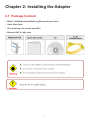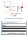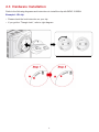
1
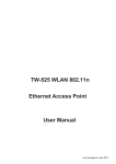
BiPAC 3100SN
Wireless-N Wall Plug
Ethernet Access Point
User Manual
FW Version 1.08e-c
Last revised on May. 2011
Safty Warnings
1. Do not use the adapter in high humidity or high temperature environment.
2. Do not open or repair the case yourself.
3. Avoid using this product and all its accesories outdoor.
4. Place the adapter on a stable surface.
5. Plug your Ethernet Access Point device directly to the AC outlet on the wall. It is best to avoid
using extension power cable as it may possess noise filter or surge protector functions that may
cause interference that may impact the performance of the device.
Table of Contents
Chapter 1: Product............................................................................. 1
1.1 Introduction............................................................................ 1
1.2 Features................................................................................. 2
Chapter 2: Installing the Adapter...................................................... 3
2.1 Package Content.................................................................... 3
2.2 Device Overview.................................................................... 4
2.3 Hardware Installation............................................................. 6
2.4 Connecting the Access Point................................................. 8
2.4.1 Power Connection.......................................................................8
2.4.2 LAN & Wireless Connection........................................................8
2.4.3 Product Application.....................................................................9
Chapter 3: Basic Network Installation ........................................... 10
3.1 Network Configuration.......................................................... 11
3.1.1 Configuring PC in Windows 7................................................... 11
3.1.2 Configuring PC in Windows Vista..............................................13
3.1.3 Configuring PC in Windows XP.................................................15
3.1.4 Configuring PC in Windows 2000.............................................16
3.1.5 Configuring PC in Windows 95/98/Me.......................................17
3.1.6 Configuring PC in Windows NT4.0............................................18
3.2 Factory Default Settings....................................................... 19
3.3 Internet Access Configuration.............................................. 20
3.3.1 Configuring with your Web Browser..........................................20
Chapter 4: Configuration................................................................. 21
4.1 Status................................................................................... 22
4.1.1 Status........................................................................................22
4.1.2 Statistic.....................................................................................23
4.2 LAN Setting.......................................................................... 24
4.2.1 LAN...........................................................................................24
4.3 Wireless Settings................................................................. 25
4.3.1 Basic Wireless Settings.............................................................26
4.3.2 Wireless Security/Encryption Settings......................................31
4.3.2.1 Secuirty Mode...................................................................................... 32
4.3.3 Advanced Wireless Settings......................................................34
4.3.4 Wi-Fi Protected Setup...............................................................35
4.3.5 AP Client...................................................................................37
4.3.6 Station List................................................................................38
4.4 Administration...................................................................... 39
4.4.1 System Management................................................................39
4.4.2 Firmware Upgrade....................................................................40
4.4.3 Settings Management...............................................................41
4.4.4 Restart......................................................................................42
Chapter 5: Troubleshooting............................................................. 43
Appendix: Product Support & Contact........................................... 44
Chapter 1: Product
1.1 Introduction
Thank you for purchasing BiPAC 3100SN Wireless-N Wall Plug Ethernet Access Point. Your
new device is an unit that extends your wireless coverage.BiPAC 3100SN can be used to bridge
Ethernet devices such as modems, routers, PCs, set-top-boxes, and game consoles, allowing
users to share network access via existing in-home power cabling.
What's unique is that the device has an extra built-in 802.11n Access Point, enabling users to
enjoy mobility, high-speed wireless connection and better coverage with no more dead zones.
Just plug BiPAC 3100SN into any wall power socket, and you can easily set up a secure wireless
network by pressing the Wi-Fi Protected Setup (WPS) button. Thus, the adapter can extend your
wireless coverage for multimedia applications such as online games, IPTV and audio streaming
from room to room.
• Extended Wireless Coverage
With an integrated 802.11n Wireless Access Point, the adapter can bridge wireless connections
of up to 6 times the speed and 3 times the wireless coverage of an 802.11b / g network device. It
supports a data rates up to 300Mbps and is also compatible with 802.11b / g equipment.
• 802.11g / 802.11n Wireless AP with WPA / WPS Support
With an integrated 802.11g / 802.11n Wireless Access Point, the device supported the features
of Wi-Fi Protected Access (WPA-PSK/ WPA2-PSK) and Wired Equivalent Privacy (WEP) which
enhance the security level of data protection and access control via Wireless LAN. The device also
supports the Wi-Fi Protected Setup (WPS) standard, allowing users to establish a secure wireless
network by simply pushing a button.
• Rich Management Interfaces
It supports flexible management interfaces with LAN and WLAN. Users can use WEB GUI through
the above interfaces to configure and manage the device.
• Web based GUI
It supports web based GUI for configuration and management. It is user-friendly
• Firmware Upgradeable
Device can be upgraded to the latest firmware through the WEB based GUI.
1
1.2 Features
• Provides physical layer data rate of up to 300Mbps over wireless
• Deliver up to 6 times speed and extended 3 times wireless coverage of a 802.11b/g network device
• WPS (Wi-Fi Protected Setup) for easy setup
• Auto channel select
• Supports Triple Play applications such as IPTV, VoIP and high-speed Internet access
• Supports 10/100 BaseT Ethernet
• Ideal for residential users
2
Chapter 2: Installing the Adapter
2.1 Package Content
• BiPAC 3100SN Wireless-N Wall Plug Ethernet Access Point
• Quick Start Guide
• CD (containing user manual and QSG)
• Ethernet (CAT-5 LAN) cable
3
2.2 Device Overview
WLAN LED
Clip Socket
Power LED
ETH LED
WPS Button
Ethernet Port
Reset Button
Power Plug
The Description of each labeled part is described in the table below.
WLAN LED
ETH (Ethernet
Link/Act) LED
Lit green when the wireless function is enabled.
Blinking when data is transmitted or received via WLAN.
Blinking quickly when WPS is proceeded.
Lit green when the device is power on.
Lit off when power is off.
Lit green when connected to an Ethernet device.
Blinking when data is transmitted or received via Ethernet port.
WPS Button
Push this button to trigger Wi-Fi Protected Setup function.
Reset Button
Press this button for more than 2 seconds until WLAN LED blinking and then
release this button to reset device to factory default settings.
Ethernet Port
Connect the Ethernet Access Point device with an Ethernet device
(e.g. computer, router, hub/switch, IP pone, IPTV set-top-box, gaming
consoles…), using the RJ-45 Ethernet cable included.
Plug into an AC outlet for power supply.
Power LED
Power Plug / AC
Power Cord
Clip Socket
Install the clip into this socket.
Note: Please DO NOT remove or disassemble the socket clip frequently
as this may cause serious damage on your Ethernet Access Point
device.
4
5
2.3 Hardware Installation
Refer to the following diagrams and instructions to install the clip with BiPAC 3100SN:
Example 1: EU clip
• Please check the lock instruction on your clip.
• If you got the “Triangle Lock”, refer to right diagram.
6
Example 2: UK clip
• Please check the lock instruction on your clip.
• If you got the “Circle Lock”, refer to right diagram.
7
2.4 Connecting the Access Point
It is easy to connect BiPAC 3100SN simply by performing the following instructions:
2.4.1 Power Connection
Plug BiPAC 3100SN into the wall outlet/socket.
2.4.2 LAN & Wireless Connection
Connect the supplied RJ-45 Ethernet cable to the Ethernet port on BiPAC 3100SN and the other
side to the device’s Ethernet interface.
You can enable wireless function to connect to the Wi-Fi devices through WPS configuration
interface or by pushing the WPS button of your 3100SN.
Note: For WPS configuration please refer to Wi-Fi Protected Setup section for more detail
description.
8
2.4.3 Product Application
9
Chapter 3: Basic Network Installation
The Ethernet Access Point can be configured through your web browser. A web browser is included
as a standard application in the following operating systems: Linux, Mac OS, Windows 98/NT/2000/
XP/Me/Vista/7, etc. The product provides an easy and user-friendly interface for configuration.
Please check your PC network components. The TCP/IP protocol stack and Ethernet network
adapter must be installed. If not, please refer to your Windows-related or other operating system
manuals.
There are ways to connect the device, either through an external repeater hub or connect directly
to your PCs. However, make sure that your PCs have an Ethernet interface installed properly prior
to connecting the device. You ought to configure your PCs to obtain an IP address through a fixed
IP address that must be in the same subnet as the device. The default IP address of the device is
192.168.1.253 and the subnet mask is 255.255.255.0 (i.e. any attached PC must be in the same
subnet, and have an IP address in the range of 192.168.1.1 to 192.168.1.252). If you encounter any
problem accessing the Ethernet Access Point web interface it is advisable to uninstall your firewall
program on your PCs, as they can cause problems accessing the IP address of the device. Users
should make their own decisions on what is best to protect their network.
Please follow the following steps to configure your PC network environment.
10
3.1 Network Configuration
3.1.1 Configuring PC in Windows 7
1. Go to Start. Click on Control Panel.
2. Then click on Network and Internet.
3. When the Network and Sharing
Center window pops up, select and
click on Change adapter settings
on the left window panel.
4. Select the Local Area Connection,
and right click the icon to select
Properties.
11
5. Select Internet Protocol Version 4
(TCP/IPv4) then click Properties.
6. In the TCP/IPv4 properties window,
click Use the following IP address
and Use the following DNS server
address radio buttons. Then click
OK to exit the setting.
7. Click OK again in the Local Area
Connection Properties window to
apply the new configuration.
12
3.1.2 Configuring PC in Windows Vista
1. Go to Start. Click on Network.
2. Then click on Network and
Sharing Center at the top bar.
3. When the Network and Sharing
Center window pops up, select
and click on Manage network
connections on the left window
column.
4. Select the Local Area Connection,
and right click the icon to select
Properties.
13
5. Select Internet Protocol Version 4
(TCP/IPv4) then click Properties.
6. In the TCP/IPv4 properties window,
click Use the following IP address
and Use the following DNS server
address radio buttons. Then click
OK to exit the setting.
7. Click OK again in the Local Area
Connection Properties window to
apply the new configuration.
14
3.1.3 Configuring PC in Windows XP
1. Go to Start > Control Panel (in Classic
View). In the Control Panel, double-click
on Network Connections
2. Double-click Local Area Connection.
3. In the Local Area Connection Status
window, click Properties.
4. Select Internet Protocol (TCP/IP) and
click Properties.
5. Click Use the following IP address and
Use the following DNS server address
radio buttons.
6. Click OK to finish the configuration.
15
3.1.4 Configuring PC in Windows 2000
1. Go to Start > Settings > Control Panel.
In the Control Panel, double-click on
Network and Dial-up Connections.
2. Double-click Local Area Connection.
3. In the Local Area Connection Status
window click Properties.
4. Select Internet Protocol (TCP/IP) and
click Properties.
5. Click Use the following IP address and
Use the following DNS server address
radio buttons.
6. Click OK to finish the configuration.
16
3.1.5 Configuring PC in Windows 95/98/Me
1. Go to Start > Settings > Control Panel.
In the Control Panel, double-click on
Network and choose the Configuration
tab.
2. Select TCP/IP > NE2000 Compatible,
or the name of your Network Interface
Card (NIC) in your PC.
3. Click Specify an IP address radio
button.
4. Click OK to finish the configuration.
17
3.1.6 Configuring PC in Windows NT4.0
1. Go to Start > Settings > Control Panel.
In the Control Panel, double-click on
Network and choose the Protocols tab.
2. Select TCP/IP
Properties.
Protocol
and
click
3. Click Specify an IP address radio
button.
4. Click OK to finish the configuration.
18
3.2 Factory Default Settings
Before configuring your adapter, you need to know the following default settings.
Web Interface (Username and Password)
Username: admin
Password: admin
The default username and password are “admin” and “admin” respectively.
Device LAN IP settings
IP Address: 192.168.1.253
Subnet Mask: 255.255.255.0
19
3.3 Internet Access Configuration
To configure this device for internet access, you must have IE 5.0 / Netscape 4.5 or above
installed on your computer. There is basically one way to configure your device before you are
able to connect to the internet: Web Interface. Configuration of this method will be discussed in
detail in the following section.
3.3.1 Configuring with your Web Browser
Open your web browser, enter the IP address of your Ethernet Adapter which the default is
192.168.1.253, and click “Go”. A user name and password window prompt will appear. The default
username and password are “admin” and “admin”.
Congratulations! You are now successfully logon to the Wireless-N Ethernet Access Point!
If the authentication succeeds, the homepage will appear on the screen.
20
Chapter 4: Configuration
Once you have logged on to your adapter GUI via your web browser, you can begin
to configure the device according to your needs. On the configuration homepage, the left
navigation pane provides the links to different setup pages. They are:
♣♣Status (Status / Statistic)
♣♣LAN Setting (LAN Setup)
♣♣Wireless Settings (Basic / Security / Advanced / WPS / AP Client / Station List)
♣♣Administration (Management / Firmware Upgrade / Settings Management / Restart)
● Each of these setup pages will be discussed in detail in the following sections.
21
4.1 Status
4.1.1 Status
● System Information
Model Name: Displays the model name.
Firmware Version: Displays the firmware version for this device.
System Up Time: Records system up-time.
Home URL: Displays the Internet address for vendor. Click to open the home page of Billion website.
● LAN
LAN IP Address: The current IP on this device.
LAN Netmask: The current subnet mask on this device.
Note: Click the LAN IP Address or LAN Netmask link to change the settings .
LAN MAC Address: The MAC address of the device.
● Wireless LAN
WLAN Service: Status of the WLAN connection.
SSID1: A unique name used to identify the wireless LAN to which a user wants to connect.
Channel: The current status in WAN interface.
Note: Click the WLAN Service, SSID or Channel link to change the settings.
22
4.1.2 Statistic
● Memory
Memory total: Displays the total memory size of the device (in bytes).
Memory left: Displays the amount of memory left (in bytes).
● LAN
LAN Rx packets: Displays the number of received packets.
LAN Rx bytes: Displays the received packet traffic (in bytes).
LAN Tx packets: Displays the number of transfered packets.
LAN Tx bytes: Displays the transfered packet traffic (in bytes)
23
4.2 LAN Setting
4.2.1 LAN
● IP Address: Enter the preferred IP address. Default is 192.168.1.253.
● Subnet Mask: Enter the preferred subnet mask. Default is 255.255.255.0.
● LAN2: This function enables the creation of multiple virtual IP interfaces for this device. It helps to connect two or more local networks to the ISP or remote node. In this case, an internal device
is not required. Default setting is Disable. If you want to active IP Alias function, please select
Enable.
● LAN2 IP Address: Specify an IP address for this virtual interface.
● LAN2 Subnet Mask: Specify a subnet mask for this virtual interface.
● UPNP: UPnP offers peer-to-peer network connectivity for PCs and other network devices, along
with the feature to control data transfer between devices. Default is Disable.
♣♣Enable: Select to activate the device’s UPnP function.
♣♣Disable: Select to inactivate the device’s UPnP function.
● Click Apply to save the changes or Cancel to recover the default setting.
24
4.3 Wireless Settings
When you click this item, the column will expand to display the sub-items that will allow you to
configure your wireless settings. You will see the following five items:
● Basic
● Security
● Advanced
● WPS
● AP Client
● Station List
The function of each configuration sub-item is described in the following sections.
25
4.3.1 Basic-Basic Wireless Settings
Wireless Network
● Wireless Service: Default setting is Enable. If you do not have any wireless, select Disable.
● Wireless Mode: The default setting is 11b+g+n mixed mode. You can adjust the wireless mode
depend on your system or enviornment.
● SSID1: The SSID is the unique name of a wireless access point (AP) used to distinguish one
from another. For the security purpose, you should change the default SSID to a unique ID name
that is difficult to guess. Make sure your wireless clients exactly have the SSID as the device in
order to connect to your network.
Note: It is case sensitive and can be up to 32 characters.
26
● Multiple SSID Service: You can select Disable,or 1, 2, 3 Extension SSID to be available at the
same time. There are totaly four SSID extensions for you to set.
● Multiple SSID isolation: If you enable this function, each SSID can not forward packet each
other.
● Client Isolation: The selection of SSIDs will depend on the Multiple SSID Service. Select each
SSID, ranging from SSID1, SSID2, SSID3 and SSID4 and set their individual configurations. If you
tick the check box, the wireless client that connected the SSID can not forward the packet each
other.
● Hide SSID: If you want to hide your SSID, you can enable it. The defult setting is disable.
● Country Region: There are seven Country Regions to be chosen, including North America,
Europe, France, etc. The Channel Frequency will be different based on this setting.
● Channel (Frequency): Select the wireless channel ID that you would like to use.
Note: Wireless performance may degrade if the selected channel ID is already being
occupied by other AP(s).
● Channel Bandwidth: Select either 20 MHz or 20/40 MHz for the channel bandwidth. The higher
the bandwidth the better the performance will be.
● BSSID: Displays the MAC address of the device.
27
Wireless Distribution System (WDS)
It is a wireless access point mode that enables wireless link and communication with other access
points. It is easy to install simply by defining the peer’s MAC address of the connected AP. WDS
takes advantage of the cost saving and flexibility which no extra wireless client device is required to
bridge between two access points and extending an existing wired or wireless infrastructure network
to create a larger network.The diagram below demonstrates the application of WDS. Be sure that
the connected devices should be in the same channel.
Configuration of WDS
Before configuring WDS, be sure that all devices should be in the same channel. Default setting is
Disable. You can enable the WDS functionality and select one of the 3 WDS Modes to build the
network connection:
● Lazy Mode
● Bridge Mode
● Repeater Mode
Lazy Mode
● Lazy Mode: Select "Lazy Mode" from the WDS Mode drop-down menu. In this case, the device
can be functioned as AP and Bridge. The AP MAC Address of WDS peers can be auto-detected.
Please note that you are not allowed to set each AP to Lazy mode. It indicates that there is at
least one AP can not be set in Lazy mode and filled the AP MAC address list.
● Wireless Security: This filed will display the encryption type in which you will set in WEP Keys
fields (Please resfer to Wireless Security/Encryption Settings section after setting up the WDS
Mode).
28
Bridge Mode
In Bridge Mode, AP will not send beacon out and deal with probe request packets, so that wireless
client will not be possible to connect with this device. The device can use complete bandwidth of
WDS connection.
● Step 1: If you want the device to be a bridge, select Bridge Mode from the drop-down menu.
● Step 2: Fill in the blank with MAC Address of the connected device(s), which display in WDS Bridge and Repeater Mode. 4 AP MAC Addresses can be filled simultaneously. it is important that your peer’s AP must include your MAC address and all of the AP's channel must be the same in WDS to acknowledge and communicate with each other.
● Step 3: Click "Wireless Security" to set the encryption keys (Please resfer to Wireless Security/ Encryption Settings section after setting up the WDS Mode).
● Step 4: Select Phy Mode. This field is available when Bridge Mode is selected. There are 4 options: CCK (11b mode), OFDM(11g mode), HTMIX (11b/g/n mode) and GREENFIELD (11n mode).
Note: Please be aware that when you key in the AP MAC address in the blank and create the
connection, you are not suggested to build the network connection via the AP Client again
since it may cause connection malfunction among divices.
29
Repeater Mode
In Repeater Mode, the packets can be forwarded to other AP via WDS connections. Here, AP
functions similarly as that in Lazy Mode, which can establish the connection with other AP(s), and
the wireless client(s) can connect the device too. It needs to input other AP MAC address(es) as
well.
● Step 1: If you want the device to be a repeater, select Repeater Mode from the WDS Mode drop-down menu.
● Step 2: Fill in the blank with MAC Address of the connected device(s), which display in WDS Bridge and Repeater Mode. 4 AP MAC Addresses can be filled simultaneously. it is important that your peer’s AP must include your MAC address and all of the AP's channel must be the same in WDS to acknowledge and communicate with each other.
● Step 3: Click "Wireless Security" to set the encryption keys (Please resfer to Wireless Security/ Encryption Settings section after setting up the WDS Mode).
Note: Please be aware that WDS may be incompatible between different products (even
from the same vendor) since it is not certified by the Wi-Fi Alliance.
30
4.3.2 Security-Wireless Security/Encryption Settings
Select SSID
● SSID choice: Select the SSID which you want to configure from the SSID list.
SSID1:Billion-3100SN
● Security Mode: You can disable or enable the wireless security function using WEP or WPA for
wireless network protection. The default mode of wireless security is disabled. Please refer to the
Security Mode section for detail descriptions (p. 31).
Wireless MAC Address Filter Table (The maximum item is 64)
● Rule: Select from the drop-down menu to choose whether the entered MAC Address should be
allowed to pass (Allow) or to be blocked (Reject). You can also disable this function.
● Add a station MAC address: Enter the MAC address of the wireless client. Then Click the Add
button to add this MAC address. Then, click "Apply" to save the settings.
Note: When the Rule is selected as “Allow”, all the MAC addresses you entered in the “Add
a station MAC address field “ will be passed; when the Policy is selected as “Reject”, all the
MAC addresses you entered in the “Add a station MAC address field” will be blocked.
31
4.3.2.1 Secuirty Mode
There are six Security Modes to be selected: WEP OPEN, WEP SHARED, WEP AUTO,
WPA-PSK, WPA2-PSK, WPA-PSK/WPA2-PSK mixed mode.
WEP OPEN / WEP SHARED / WEP AUTO
● Security Mode: Select WEP OPEN, WEP SHARED or WEP AUTO from the drop-down
menu.
● Encryption Type: Only be available in WEP SHARED mode. You can select WEP or None.
WEP
● Default Key (1~4): Select the encryption key ID.
● WEP Keys (1~4): Enter the key to encrypt wireless data. To allow encrypted data
transmission, the WEP Encryption Key values on all wireless stations must be the same as
the device. There are four keys for your selection. The input format is in Hex or ASCII style.
You can type 5 and 13 ASCII character required for 64bit and 128bit WEP key or 10 and 26
Hex codes required for 64bit and 128bit WEP key respectively.
32
WPA-PSK / WPA2-PSK / WPA-PSK/WPA2-PSK mix mode
WPA
● Security Mode: Select WPA-PSK, WPA2-PSK or WPA-PSK/WPA2-PSK mix mode from the
drop-down menu. The encryption key should be entered in PSK (Pre-Shared Key)
● WPA Algorithms: There are 3 types of the TKIP, AES & TKIP/AES mix mode (not available in
WPA-PSK mode).
● TKIP / AES: Enter the encryption key (8~63 ASCII characters or 64 Hex characters).
● Pass Phrase: Enter a pass phrase to access the network. It can be a password like “12345678”
or a pass phrase, from 8 to 63 case-sensitive characters.
● Key Renewal Interval: The period of renewal time (in seconds) for changing the security key
automatically between wireless client and Access Point (AP). Default value is 3600 seconds.
33
4.3.3 Advanced-Advanced Wireless Settings
Advanced Settings
● Tx Power: Tx Power measurement enhances the wireless transmission signal strength. You
can adjust this power level from minimum (0) to maximum (100). Default is 100.
● Tx Burst: This feature is used to activate the transmitted time slot to increase transmission
throughput. Default is Enable.
Wi-Fi Multimedia
● WMM Capable: This feature is used to control the prioritization of traffic according to 4 Access
categories: Voice, Video, Best Effort and Background. Default is Enable.
● APSD Capable: Automatic Power Save Delivery (APSD) is an efficient power management
mechanism that can help to consume less power and is very useful for phones that support VoIP.
You can select enable or disable of this feature. Default is Disable.
IGMP Snooping
● IGMP Snooping Service: IGMP refers to Internet Group Management Protocol. IGMP Snooping
Service manages the wireless transmission of any incoming IGMP multicast packet groups
between the wireless station and the AP. Default is Enable. The multicast traffic will be forwarded
to the links that belong to milticast groups.
34
4.3.4 WPS-Wi-Fi Protected Setup
WPS feature is designed to ease security setup and enabled WiFi networks in small offices or
home. It helps you to set a network and enable security by entering a PIN or pushing the WPS
button.
WPS Configration
● WPS Service: Default setting is Disable. If you want to activate this function, please select
Enable and click Apply to confirm the setting.
● WPS mode: There are two methods to connect the network via WPS between AP and Stations:
PIN code or PBC.
♣♣PIN: Select PIN (Personal Identification Number) mode to connect to the device.When PIN
mode is selected, it allows you to enter the PIN code or select Enrollee to use the default PIN code
(00000864) which the device uses to authenticate other WPS-enabled wireless devices.
♣♣PBC: Select PBC (Push Button Communication) mode to connect to the device.
Note: You can enable WPS PBC mode through WPS configuration interface as above or by
pushing the WPS button of your Wall Plug Ethernet Access Point for more than 2 seconds
and release it. The WPS will establish the wireless connection automatically after the
wireless station also start WPS PBC process.
● Click Apply to save the change.
35
WPS Summary
● WPS Current Status: Displays the WPS status.
● WPS Configured: Displays the current WPS configuration status
● WPS SSID: Displays the WPS network name.
● WPS Authentication Mode: Displays the authentication mode for WPS.
● WPS Encryption Type: Displays the encryption type for WPS.
● WPS Default Key Index: Displays the Default Key Index.
● WPS Key(ASCII): Displays the WPS key (ASCII characters).
● AP PIN: Displays the Access Point's PIN number.
36
4.3.5 AP Client
The AP Client provides the new function of wireless client for AP. It not only enables one AP to
connect to another one within its wireless coverage but keeps its original AP function at the same
time. The use of AP client is more convenient than that of WDS for AP connections.
Wireless AP List
In the AP list,you can see the channel, SSID, MAC Address, Security, Signal and Wireless Mode
of the searched working APs in the neighborhood. To connect two APs, please follow the steps
below. Click “Refresh AP List” to renew the wireless AP List.
• Step 1: Click the “AP Selection” radio button to select the specified AP you want to connect. the AP information will show up in the bottom of the screen.
• Step 2: If the AP selected have security, you need to provide the same security key to build
the safety connection.
• Step 3: If the AP hids the SSID, you must input the SSID manually.
• Step 4: Click “Enable” If you want to activate the AP Client Service.The default setting is disable.
• Step 5: Click”Apply” buttont to confirm the setting.
Note:
1. It should be noted that the channel will be changed as the same as the AP selected after clicking “Apply” button to enable AP Client Service.
2. If the AP to be connected is not shown on the AP List, you should click one of the radio
button and click “Edit” at the bottom of the screen to enter SSID manually.
37
4.3.6 Station List
The Station List displays the Wireless Network information.
Wireless Network
● MAC Address: The MAC address of the wireless station which connected to the AP.
● Aid: The association ID.
● PSM: The power save mode.
● MimoPS: The MIMO power save mode. MIMO, Multiple-input and multiple-output, is the use of
multiple antennas at both the transmitter and receiver to improve communication performance.
● MCS: The Modulation and Coding Scheme.
● BW: The wireless channel bandwidth.
38
4.4 Administration
4.4.1 System Management
Administrator Settings
● Account: You are allowed to set your own account name. Default is admin.
● Password: You are allowed to set your own password. Default is admin.
● Click Apply to save the change.
39
4.4.2 Firmware Upgrade
Upgrading the newly improved version of the firmware allows you to use newly integrated
features.
Firmware Upgrade
● Location: Click Browse to select the new firmware image file you have downloaded to your PC. Once the correct file is selected, click Apply to update the firmware of your device.
Note: DO NOT perform any actions while the firmware is being upgraded.
● The system will automatically reboot once the upgrade is complete. You will be returned to the
Status page.
40
4.4.3 Settings Management
These functions allow you to save a backup of the current configuration of your device to a
defined location on your PC, to restore a previously saved configuration, and to restart your device
with the factory default settings. This is useful if you wish to experiment with different settings,
knowing that you have a backup in hand in case any mistakes occur.
Export Settings
● Export Button: Click Export to open or save the backup file. Then, select the location to store
the setting file on your PC. You may also change the name of the file if you wish to keep multiple
backups.
Note: It is advisable that you should backup your device configuration before making any
changes to your device configuration.
Import Settings
● Settings file location: Click Browse to select a file from your PC to restore. You should only
restore your device setting that has been generated by the Backup function which is created with
the current version of the device firmware. Settings files saved to your PC should not be manually
edited in any way.
● Select the settings files you wish to use, and press Import to load the setting into the device.
41
4.4.4 Restart
These functions allow you to restart the device to factory default setting after you have
accidentally changed your settings that may result in undesirable outcome.
Restart
● Restart device with Factory Default Settings or Current Settings to determine how the AP will
restart. Click the Restart button to restart your device. The system will automatically reload Status
page after reboot complete
● You may also reset your device to factory settings by holding the small Reset pinhole
button for more than 2 seconds until the WLAN LED blinking and then release it.
Note: Do NOT perform any actions while the device is being restarted.
42
Chapter 5: Troubleshooting
If your device does not function properly, please refer to the suggested solutions provided in this
chapter. If your problems persist or the suggested solutions do not meet your needs, please kindly
contact your service provider or Billion for support.
Problems with the device
Problem
Suggested Solutions
I forgot my password.
First, try entering the default user name and password:
User Name: admin; Password: admin (Both the User Name
and Password are case sensitive, so make sure that CAPS
LOCK is not on when entering this information).
If this fails, restore your device to its factory default settings and
then enter the default user name and password.
I can not access the LOGIN • Ensure you are using the correct IP address. (Default is
Web Configuration Interface. 192.168.1.253.)
• Check the hardware connections and ensure all LEDs are
behaving as excepted.
• Ensure your computer’s IP address is in the same subnet as
the Ethernet Access Point device.
• Check to see if your browser has Java, JavaScript, or ActiveX
enabled. If you are using Internet Explorer, click Refresh to
ensure that the Java applet is loaded.
• Try closing the browser and re-launching it.
• Reset the device to factory defaults and try to acess the Ethernet Access Point with the default IP address.
How do I reset the Ethernet There are two ways to reset factory default settings:
Access Point?
• Hardware Reset
To perform a hardware reset, hold down the reset button for
more than 2 secondsand release it.
• Software Reset
To initiate a software reset, select Administration > Restart, click
Factory Default Setting radio box and press Apply button to initiate the restart process. Then wait for about 35 seconds.
Note: Restoring to factory default will wipe out all the
configurations you have previously set. You are strongly
advised to create a backup copy of the settings before
resetting the device.
I can not start my Ethernet
Please check your power supply is working. Wall Plug Ethernet
Access Point device.
Access Point device operates from the power supplied by the
home electrical wiring and can not operate without a working
power supply.
43
Appendix: Product Support & Contact
If you come across any problems please contact the dealer from where you purchased your
product.
Contact Billion
Worldwide:
http://www.billion.com
MAC OS is a registered Trademark of Apple Computer, Inc.
Windows 98, Windows NT, Windows 2000, Windows Me, Windows XP, Windows Vista and Windows 7 are
registered Trademarks of Microsoft Corporation.
44