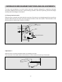
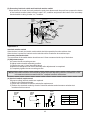
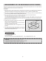
1
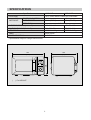
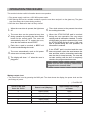
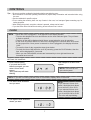
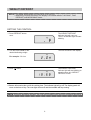
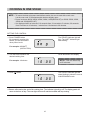
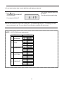
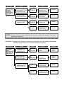
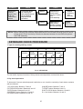
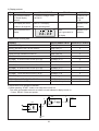
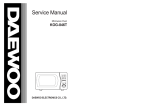
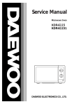
Service Manual
Microwave Oven
Model: KOR-616T0A
KOR-816T0A
KOR-616T1A
DAEWOO ELECTRONICS CO., LTD.
PRECAUTIONS TO BE OBSERVED BEFORE AND
DURING SERVICING TO AVOID POSSIBLE EXPOSURE
TO EXCESSIVE MICROWAVE ENERGY
(a) Do not operate or allow the oven to be operated with the door open.
(b) Make the following safety checks on all ovens to be serviced before activating the
magnetron or other microwave source, and make repairs as necessary: (1) Interlock
operation, (2) proper door closing, (3) seal and sealing surfaces (arcing, wear, and other
damage), (4) damage to or loosening of hinges and latches, (5) evidence of dropping or
abuse.
(c) Before turning on microwave power for any service test or inspection within the microwave generating compartments, check the magnetron, wave guide or transmission line,
and cavity for proper alignment, intergrity, and connections.
(d) Any defective or misadjusted components in the interlock, monitor, door seal, and
microwave generation and transmission systems shall be repaired, replaced, or
adjusted by procedures described in this manual before the oven is released to the
owner.
(e) A microwave leakage check to verify compliance with the Federal performance
standard should be performed on each oven prior to release to the owner.
TABLE OF CONTENTS
PROPER USE AND SERVICE PRECAUTIONS ....................................................................................................2
SPECIFICATIONS ...................................................................................................................................................3
FEATURES DIAGRAM ............................................................................................................................................4
INSTALLATION ........................................................................................................................................................5
OPERATION PROCEDURE....................................................................................................................................6
CONTROLS .............................................................................................................................................................7
INTERLOCK MECHANISM FUNCTIONS AND ADJUSTMENTS........................................................................17
MEASUREMENT OF THE MICROWAVE OUTPUT POWER..............................................................................19
WIRING DIAGRAM................................................................................................................................................21
CIRCUIT DESCRIPTION.......................................................................................................................................22
SAFETY PRECAUTIONS FOR DISASSEMBLY AND REPAIR ...........................................................................25
DISASSEMBLY AND ASSEMBLY.........................................................................................................................26
TROUBLE SHOOTING GUIDE .............................................................................................................................31
COMPONENT TEST PROCEDURE.....................................................................................................................36
SAFETY INTERLOCK CONTINUITY TEST .........................................................................................................37
PRINTED WIRING BOARD...................................................................................................................................38
CIRCUIT CHECK PROCEDURE .....................................................................................................................38
P.C.B. CIRCUIT DIAGRAM ..............................................................................................................................44
COMPONENT INFORMATION ........................................................................................................................45
PRINTED CIRCUITS BOARD..........................................................................................................................46
P.C.B. LOCATION NO. .....................................................................................................................................48
EXPLODED AND PARTS LIST .............................................................................................................................50
1
CAUTION: This Device is to be Serviced Only by Properly Qualified Service Personnel. Consult the
Service Manual for Proper Service Procedures to Assure Continued Safety operation and
for Precautions to be Taken to Avoid Possible Exposure to Excessive Microwave Energy.
PROPER USE AND SERVICE PRECAUTIONS
1. For Safe Operation
Damage that allows the microwave energy(that cooks or heats the food) to escape will result in poor
cooking and may cause serious bodily injury to the operator.
IF ANY OF THE FOLLOWING CONDITIONS EXIST, OPERATOR MUST NOT USE THE
APPLIANCE.
(Only a trained service personnel should make repairs.)
1) A broken door hinge.
2) A broken door viewing screen.
3) A broken front panel, oven cavity.
4) A loosened door lock.
5) A broken door lock.
The door gasket plate and oven cavity surface should be kept clean.
No grease, soil or spatter should be allowed to build up on these surfaces or inside the oven.
DO NOT ATTEMPT TO OPERATE THIS APPLIANCE WITH THE DOOR OPEN. The microwave
oven has concealed switches to make sure the power is turned off when the door is opened.
Do not attempt to defeat them.
DO NOT ATTEMPT TO SERVICE THIS APPLIANCE UNTIL YOU HAVE READ THIS SERVICE
MANUAL.
2. For Safe Service Procedures.
1) If the oven is operative prior to servicing, a microwave emission check should be performed prior to
servicing the oven.
2) If any certified oven unit is found to have excessive emission level 5mW/cm 2, the service
person should:
(a) inform the manufacturer, importer or assembler,
(b) repair the unit at no cost to the owner,
(c) attempt to ascertain the cause of the excessive leakage,
(d) tell the owner of the unit not to use the unit until the oven has been brought into compliance.
3) If the oven operates with the door open, the service person should tell the user not to operate the
oven and contact the manufacturer and CDRH immediately.
2
SPECIFICATIONS
Specifications
KOR-816T
Power Supply
MICROWAVE
KOR-616T
120V ~ 60Hz, SINGLE PHASE WITH EARTHING
POWER CONSUMPTION
1200 W
920 W
OUTPUT POWER
800 W (IEC 705)
600 W (IEC 705)
FREQUENCY
2450 MHz
OUTSIDE DIMENSIONS (W x H x D)
495 x 289 x 409 mm
465 x 274 x 372 mm
CAVITY DIMENSIONS (W x H x D)
320x 225 x 330 mm
290x 200 x 290 mm
NET WEIGHT
APPROX. 14.0Kg
APPROX. 12.5Kg
TIMER
60 min. 00 sec
POWER SELECTIONS
5 LEVELS
* Specifications subject to change without notice.
409
(372)
495
(465)
Stop
1
Defrost
Quantity Weight
Time
2
Lock
Auto cook
Power
lb
Defrost
Watt
oz
+1min
More
STOP
START
CLEAR
Speedy
289
(274)
Auto Cook
1. Beveroge
2. Soup
3. Casserole
4. Vegetable
5. Fish Fillets
T
(
r/Weight/Quanti
t
ime
y
Less
Clock
) : For KOR-616T
3
FEATURES DIAGRAM
1
2
3
5
4
Stop
1
Defrost
Quantity Weight
Time
2
9
Stop
1
Defrost
Quantity Weight
Time
2
Lock
Auto cook
Power
l
Watt
Defrost
Auto Cook
STOP
START
CLEAR
Speedy
Power
Watt
oz
+1min
w
Auto Cook
1. Beveroge
2. Soup
3. Casserole
4. Vegetable
5. Fish Fillets
r/Weight/Quanti
t
ime
T
Clock
lb
Defrost
0
q
y
Less
Auto cook
oz
+1min
1. Beveroge
2. Soup
3. Casserole
4. Vegetable
5. Fish Fillets
More
Lock
e
STOP
START
CLEAR
Speedy
r
t
More
y
6
i
Clock
T
u
Less
r/Weight/Quanti
t
ime
y
7
8
¤
Door latch - When the door is closed it will automatically lock shut. If the door is opened while the
oven is operating, magnetron will immediately stop operating.
¤Ł Door seal - Door seal maintains the microwave energy within the oven cavity and prevents microwave
leakage.
¤Ø Oven cavity.
¤Œ Spatter shield - Protects the microwave outlet from splashes of cooking foods.
¤º Safety interlock system.
¤
Door viewing screen - Allows viewing of food. The screen is designed so that light can pass through,
but not the microwaves.
¤ Glass cooking tray - Made of special heat resistant glass. Food in a proper receptacle is placed on
this tray for cooking.
¤
Roller guide - This must always be used for cooking together with the glass cooking tray.
¤
Display - Cooking time, power level, present time are displayed.
¤ ¤æ ¤ Function buttons - Used to select desired oven operation.
: MICROWAVE, DEFROST, AUTOCOOK.
¤
+1 min. button - Used to increase time of operating.
¤
Start button - Used to start a selected operation. When lamp blinks, press the start button.
Speedy cook button - Used to set desired time.(It is incresed 30 seconds.)
¤ı Stop/clear button - Used to pause or clear all information manually put into the oven control panel
except clock.
§ §æ More/Less button - Used to select auto cook time. (More/less 10% of auto cook time)
§
Clock button - Used to set and recall the time of day.
§
Dial knob - Used to set the cooking time, weight and quantity.
§
Guide lamp - When blinking it informs you to be ready to operte dial knob.
4
p
o
INSTALLATION
1
STEADY, FLAT LOCATION
This microwave oven should be set on a steady, flat surface.
2
LEAVE SPACE BEHIND AND SIDE
All air vents should be kept a clearance. lf all vents are covered during operation, the oven may overheat
and, eventually, cause oven failure.
3
AWAY FROM RADIO AND TV SETS
Poor television reception and radio interference may result if the oven is located close to a TV, Radio, or
antenna, feeder and so on.
4
AWAY FROM HEATING APPLIANCES AND WATER TAPS
Keep the oven away from hot air, steam or splash when choosing a place to position it, or the insulation
might be adversely affected and breakdowns occur.
5
POWER SUPPLY
• Check your local power source. This oven must be plugged into at least at 12 Amp 120 Volt, 60Hz
grounded outlet.
• Power supply cord is about 1.0 meters long.
1. A short power-supply cord is provided to reduce the risks resulting from becoming entangled in or tripping
over a longer cord.
2. Longer cord sets or extension cords are available and may be used if care is exercised in their use.
3. If a long cord or extension cord is used, (1) the marked electrical rating of the cord set or extension cord
should be at least as great as the electrical rating of the appliance, (2) the extension cord must be a
grounding-type 3-wire cord, and (3) the longer cord should be arranged so that will not drape over the
countertop or tabletop where it can be pulled on by children or tripped over accidentally.
When use 3-pronged plug
When use grounding adaptor, make sure the
receptacle box is fully grounded
3-prong Receptacle
Receptacle Box Cover
Grounding Lead
Receptacle
Box cover
Grounding Adaptor
Receptacle
3-prong plug
6
EXAMINE THE OVEN AFTER UNPACKING FOR ANY DAMAGE SUCH AS:
Dents, a misaligned door, broken door, a dent in cavity.
If any of the above are visible, DO NOT INSTALL, and notify dealer immediately.
5
OPERATION PROCEDURE
This section includes useful information about oven operation.
1. Plug power supply cord into a 120V 60Hz power outlet.
2. After placing the food in a suitable container, open the oven door and put it on the glass tray. The glass
tray must always be in place during cooking.
3. Shut the door. Make sure that it is firmly closed.
1
When the oven door is opened, the light turns
off.
6
Time clock returns to the present time when
the cooking time ends.
2
The oven door can be opened at any time
during operation by touching the door release
button on the control panel. The oven will
automatically shut off. To restart the oven,
close the door and then touch START.
7
3
Each time a pad is touched, a BEEP will
sound to acknowledge the touch.
When the STOP/CLEAR pad is touched
during the oven operation, the oven stops
cooking and all information retained. To erase
all information (except the present time), touch
the STOP/CLEAR pad once more. If the oven
door is opened during the oven operation, all
information is retained.
8
If the START pad is touched and the oven
does not operate, check the area between the
door and door seal for obstructions and make
sure the door is closed securely. The oven will
not start cooking until the door is completely
closed or the program has been reset.
4
The oven automatically cook on full power
unless set to a lower power level.
5
The display will show “ :0” when the oven is
plugged in.
Make sure the oven is properly installed and
plugged into the electrical outlet.
Wattage output chart
• The power-level is set by pressing the M/W pad. The chart shows the display, the power level and the
percentage of power.
(
) : For KOR-616T
Touch Power pad,
Once the Touch
Power Level (Display)
Approximate Percentage
of Power
5
800W (600W)
100%
4
650W (500W)
80%
3
450W (350W)
60%
2
300W (250W)
40%
1
140W (100W)
20%
6
CONTROLS
Tips: • Be sure to read the cookbook's introduction before operating the oven.
• Also remember to read this operating instruction for proper safety information and instruction bfore using
the oven.
• See the cookbook for specific recipes.
• Prior to setting the controls, place one cup of water in the oven, in a heat-proof glass measuring cup, for
testing purposes.
• When setting the controls, everytime a button is pressed, a beep can be heard.
• If you don't take off the food after end cooking, buzzer will sound as 1 minute.
CLOCK
NOTE: • When the oven is plugged in, “0:00”appears in the display window.
• The two dots between the hour and minute are the clock indicator lights. They will start
to flash on and off.
• The time of day will be displayed at all times, except when the oven is operating.
• In the oven of a power failure or if the oven is unplugged, the clock will have to be reset
for the proper time. Once power is restored or oven is plugged in, the display will show
“0:00”.
• To reset the time of day, repeat the steps given below.
• To check the time of day while the oven is poerating, press the CLOCk button, then the
time will be displayed for 3 seconds.
• When you turn DIAL KNOB, minutes are increased by to turn right and hours are
increased as to turn left.
SETTING THE CONTROL
1. Press CLOCK button.
If you push the CLOCK
button once again, you can
select 12 hour clock
system.
Then guide lamp will starts
blinking.
This example is 24 hour clock
system.
NOTE: This oven is multiple clock system.
NOTE: If you are not setting current time for 3 seconds, display return to old time.
2. Turn left the DIAL KNOB for
hour you want.
NOTE:
• If you selected 12 hour clock
system, this digital clock allows
you to set from 1:00 to 12:59.
• If you selected 24 hour clock
system, this digital clock allows
you to set from 0:00 to 23:59.
• The colon will stop blinking.
3. Turn right the DIAL KNOB for
minute you want.
7
4. Press CLOCK button.
The display will show present
time, and the colon starts
blinking.
This digital clock allows you to set
to “10:10”
TIME DEFROST
SETTING THE CONTROL
1. Press DEFROST button
twice.
This TIME DEFROST indicator
light will light up.
Time
20:00 will show in the display.
2. Turn the DIAL KNOB for the
desired defrosting time.
Time
For example: 20 minutes.
3. Press
button.
Time
NOTE: Time can be set up
to 60 minutes.
The TIME DEFROST indicator
light will start blinking to show the
oven is in TIME DEFROST
mode.
4. Buzzer will sound at the end of the cooking time. The indicator light will go off. The display panel will
return to the time of day. The oven light will turn off and the turntable will stop turning.
NOTE: During the defrosting operation, turn over after buzzer sound for completed defrosting.
8
WEIGHT DEFROST
NOTE :• This digital weight allows you set from 8 oz to 6 lb 8 oz.
• Whenever you press this button, the display is circulated WEIGHT DEFROST, TIME
DEFROST, and MICROWAVE mode.
SETTING THE CONTROL
1. Press DEFROST button
once.
The WEIGHT DEFROST
indicator light will come on.
The lb, oz indicator light will start
blinking.
Weight
lb
oz
The 204 will show in the display.
2. Turn the DIAL KNOB for the
desired defrosting weight.
Weight
For example: 2 lb 4 oz
lb
3. Press
oz
button.
Weight
The WEIGHT DEFROST
indicator light will start blinking to
show the oven is in WEIGHT
DEFROST mode.
4. Buzzer will sound at the end of the cooking time. The indicator light will go off. The display panel will
return to the time of day. The oven light will turn off and the turntable will stop turning.
NOTE: During the defrosting operation, turn over the food after buzzer sound for completed defrosting.
9
COOKING IN ONE STAGE
NOTE : • To insure the best microwave and defrost results, be sure to start with a cool oven.
Let the oven cool 15~20minutes with the door slightly open.
• Power levels are 800W, 650W, 450W, 300W, 140W(KOR-816T) or 600W, 500W, 350W,
250W and 100W(KOR-616T)
• It is displayed after an interval of 10 seconds from 10 seconds to 5 minutes, 30 seconds
from 5 minutes to 10 minutes, 1 minute from 10 minutes to 60 minutes.
SETTING THE CONTROL
1. Press POWER button
By repeatedly pressing this
button, you can also select
other power levels.
The STAGE1 indicator light will
light. The WATT indicator light
start blinking.
Stage
1
Watt
For example: 800WATT
(KOR-616T:600)
2. Turn the DIAL KNOB for the
desired cooking time.
10:00 will show in the display.
Stage
1
For example: 10minutes
3. Press
NOTE: Time can be set up
to 60 minutes.
The STAGE1 indicator light will
starts blinking to show the oven is
in MICROWAVE mode.
button.
Stage
1
4. Buzzer will sound at the end of the cooking time. The indicator light will go off. The display panel will
return to the time of day. The oven light will turn off and the turntable will stop turning.
10
COOKING IN TWO STAGES
NOTE : For best results, some recipes call for one power level for a certain length of time and
another power level for a different length of time.
SETTING THE CONTROL
1. Press POWER button more
than three times.
By repeatedly pressing this
button, you can also select
other power levels.
The STAGE1 indicator light will
light.
The WATT indicator light start
blinking.
Stage
1
Watt
For example: 450WATT
(KOR-616T:350WATT)
2. Turn the DIAL KNOB for the
desired cooking time.
10:00 will show in the display.
Stage
1
For example: 10 minutes
NOTE: Time can be set up
to 60 minutes.
3. Press POWER button
By repeatedly pressing this
button, you can also select
other power levels.
The STAGE2 indicator light will
light
The WATT indicator start blinking.
Stage
2
Watt
For example:800WATT
(KOR-616T:600W)
4. Turn the DIAL KNOB for the
desired cooking time.
18:00 will show in the display.
Stage
2
For example: 18minutes
NOTE: Time can be set up
to 60 minutes.
11
5. Press
When you touch START, both
STAGE1 & 2 indicator lights come
on.
STAGE1 indicator light blinking to
show you that the oven is cooking in
the first of two cook stages.
The oven will cook at the power you
selected for stage 1.
button.
Stage
1
2
At the end of stage 1, the oven will
beep and start the second stage 2.
The STAGE1 indicator light will go off
and the STAGE2 indicator light starts
blinking. The display counts down the
time to show you how much cooking
time is left in the second stage.
Stage
2
6. Buzzer will sound at the end of the cooking time. The indicator light will go off. The display panel will return to the
time of day. The oven light will turn off and the turntable will stop turning.
12
AUTO COOK
NOTE : • There is programmed for cooking of five kinds (1~5)
• You don't have to worry about setting time, power and function.
SETTING THE CONTROL
You can operate MORE or LESS than programmed time as pressing MORE or LESS button whenever
MORE or LESS button, display is changed “10” or “-10”.
10: Adds 10% for programmed time.
-10: Romove 10% for prjogrammed time.
1. Press AUTO COOK button
Quantity
The AUTO COOK indicator light
will light “AC-1” will show in the
display.
Auto cook
2. Select the desired cooking.
For example: SOUP
Press AUTO COOK button
twice.
Quantity
“AC-2” will show in the display.
The quantity indicator light will
start blinking
Auto cook
3. If you want to select other menu, press AUTO COOK button until display your desired cooking menu.
4. Turn the DIAL KNOB for
desired cooking quantity.
Auto cook
5. Select the desired cooking
quantity.
For example: 3(12.3oz)
“3” will show in the display.
Auto cook
13
6. If you want to select other, turn the dial Knob until display you desired.
The oven will now start auto cook
for menu2.
The indicator light starts blinking.
7. Press
button.
This example don't set MORE
or LESS function.
For example: KOR-616T
Auto cook
8.Buzzer will sound at the end of the cooking time. The indicator light will go off. The display panel will
return to the time of day. The oven light will turn off and the turntable will stop turning.
NOTE : • AUTO COOK menu and quantity.
MENU NO
1
BEVERAGE
2
SOUP
3
CASSEROLE
4
VEGETABLE
5
FISH FILLET
QUANTITY NO
1
2
3
1
2
3
4
1
2
3
4
1
2
3
4
1
2
3
4
5
1 CUP
2CUPS
3CUPS
8.8 oz
10.6 oz
12.3 oz
14.1 oz
7.1 oz
14.1 oz
1 lb 5 oz
1 lb 12 oz
8.8 oz
10.6 oz
12.3 oz
14.1 oz
10.6 oz
14.1 oz
1 lb 2 oz
1 lb 5 oz
1 lb 9 oz
14
SPEEDY COOK
SETTING THE CONTROL
Whenever the button is pressed,
cooking time is increased 30
seconds.
If the time was setting, this oven
is operated automatically after 2
seconds to microwave high power.
1. Press
button.
Then start lamp will start
blinking.
NOTE: This key is increased from 30 seconds to 5 minutes.
If you are pressing more than about 0.5 seconds, the time is increased 30 seconds continuously.
CHILD SAFTY LOCK
• The safty lock prevents unwanted oven operation such as by small children.
• To set, press STOP/CLEAR for 3 seconds, lock indicator light starts blinking.
• To cancel, press STOP/CLEAR for 3 seconds, lock indicator goes off.
+1 min.
• The function can use when oven is working state.
• Whenever press this button, time is increased as 1 minute.
• Time is increased until 60 minutes.
STAGE COMVINATIONS
This oven has the ability to be programmed to do up to three consecutive functions. These
combinations are five below and either the complete program or part of it can be used.
STAGE COOKING
TIME / WEIGHT
DEFROST
STAGE 1 (M/W)
STAGE 2 (M/W)
¡ When you set stage mode, indicator is lighted only setting.
¡ When you press START button, all indicators are lighted setted function.
Indicator of operating function is blinking.
15
TO STOP THE OVEN WHILEITIS OPERATING
1. Press
(STOP/CLEAR) button.
-Touch once more to erase all instruction except clock.
-You can restart the oven by touching
(START) button.
2. Open the door
-You can restart the oven by closing the door and touching
button.
NOTE : Oven stops operating when door is opened.
ERASING INSTRUCTIONS
• TOUCH
(STOP/CLEAR)button to erase all instructions you set previously.
• Opening the oven door during cooking dose not erase cooking instruction.
• If you push twice
button during operation, the cooking instruction is all erased.
GENERAL COOKING HINTS
1. When cook a roast with an excess amount of drippings, it is helpful to remove the drippings at
turnover time to prevent spattering.
2. Prick the meats, fish or poultry with a fork to prevent bursting.
Steam builds up pressure in meats, fish or poultry which are tightly covered by a skin or membrane.
3. Reduce suggested cooking times, It is always better to undercook foods rather than to over-cook them.
If a range of times is stated in a recipe, cook the minimun suggested time, check for doneness, and then
cook slightly longer if necessary.
16
INTERLOCK MECHANISM FUNCTIONS AND ADJUSTMENTS
The door lock mechanism is a device which has been specially designed to completely eliminate
microwave radiation when the door is opened during operation, and thus to perfectly prevent the danger
resulting from the leakage of microwave.
(1) Primary interlock switch
When the door is closed, the hook locks the oven door. If the door is not closed properly the oven will not
operate. When the door is closed, the hook pushes the button of the micro switch. Then the button of the
primary interlock switch bring it under on condition.
Latch
Mounting serew
Button
Hook
Primary interlock switch
Adjustment 1.
1.2mm
When the door is closed, the switch button is pushed by the hook.
The movement of the switch button should exceed 1.2mm measured at the top of the button.
17
(2) Secondary interlock switch and interlock monitor switch
When the door is closed, the hook pushes the push lever down ward, the push lever presses the button
of the interlock monitor switch to bring it under “off”, condition and presses the button of the secondary
interlock switch to bring it under “on”, condition.
Monitor
interlock
switch
Secondary
interlock
switch
Hook
Push lever
Adjustment 2.
Interlock monitor switch
When the door is closed, the interlock monitor switch should be opened before other switches close.
When the door is opened, the interlock monitor switch should be closed after other switches open.
Secondary interlock switch
The movement of the switch button should exceed 1.2mm measured at the top of the button.
(3) Adjustment steps
a) Loosen the two mounting screws.
b) Adjust interlock switch assembly position.
c) Confirm the gap (1.2mm) described above.
d) Make sure that push lever moves smoothly after adjustments in completed.
e) Completely tighten the two mounting screws.
NOTE: Microwave emission test should be performed after adjusting interlock mechanism. If the
microwave emission exceed 4mW/cm2, readjust interlock mechanism.
(4) Interlock switch resplacement
Whenever safety interlock switch are replaced:
1) Refer to the following diagram.
2) Check the connection of monitor switch after replacement.
3) Perform the electrical continuity check of interlock switches and microwave emission test
mentioned in this manual.
Secondary
interlock
switch
Primary
interlock
switch
Interlock
Monitor
switch
BK
BL
BL
BK
BL
RD RD
BK
RD
18
WH
BK
SYMBOL
COLOR
RD
RED
BK
BLACK
BL
BLUE
MEASUREMENT OF THE MICROWAVE OUTPUT POWER
Microwave output power can be checked by indirectly measuring the temperature rise of a certain amount
of water exposed to the microwave as directed below.
Procedure
1. Microwave power output measurement is made with the microwave oven supplied at rated voltage and
operated at its maximum microwave power setting with a load of 1,000±5cc of potable water.
2. The water is contained in a cylindrical borosilicate glass vessel having a maximum material thickness
of 3 mm and an outside diameter of approximately 190 mm.
3. The oven and the empty vessel are at ambient temperature prior to the start of the test.
The initial temperature of the water is 10±2°C (50±3.6°F).
It is measured immediately before the water is added to the vessel. After addition of the water to the
vessel, the load is immediately placed on the center of the shelf which is in the lowest normal position.
4. Microwave power is switched on.
Water Load
5. Heating time should be exactly 52 seconds (KOR816T) or 70 seconds (KOR-616T).
Heating time is measured while the microwave
generator is operating at full power.
The filament heat-up time for magnetrons is not
included.
6. The initial and final water temperatures are select-ed
so that the maximum difference between the ambient
and final water temperatures is 5K.
Tray
7. The microwave power output P in watts is calculated from the following formula:
P = 4187 x ¡ T/t
• ¡ T is actual temperature rise.
• t is the heating time.
The power measured should be 800W(KOR-816T)¡ 10% or 600W(KOR-616T) ± 10%
CAUTION:
1. Water load should be measured exactly to 1 liters.
2. Input power voltage should be exactly 120 volts as specified.
3. Ambient temperature should be 20±2°C (68±3.6°F)
19
MICROWAVE RADIATION TEST
WARNING
Make sure to check the microwave leakage before and after repair or adjustment.
• Always, start measuring of an unknown field to assure. Safety for operating personnel from microwave
energy.
• Do not place your hands into any suspected microwave radiation field unless the safe density level is
known.
• Care should be taken not to place the eyes in direct line with the source of microwave energy.
• Slowly approach the unit under test until the radiometer reads an appreciable microwave leakage from
the unit under the test.
Procedure
A) Prepare Microwave Energy Survey Meter, 600cc glass beaker, glass thermometer 100°C or 212°F.
B) Pour 275cc¡ 15cc of tap water initially at 20¡ 5°C (68¡ 9°F) in the 600cc beaker with an inside diameter
of approx. 8.5cm (3.5 in).
C) Place it at the center of the tray and set it in a cavity.
D) Close the door and operate the oven.
E) Measure the leakage by using microwave energy survey meter with dual ranges, set to 2,450 MHz.
-Measured radiation leakage must not exceed the values prescribed below.
• Leakage for a fully assembled oven with door normally closed must be less than 4mW/cm2.
-When measuring the leakage, always use the 2 in (5cm) space cone with probe. Hold the probe
perpendicular to the cabinet, door. Place the space
cone of the probe on the door, cabinet, door seam,
door viewing screen, the exhaust air vents and the
suction air vents.
-Measuring should be in a counter-clockwise direction
at a rate of 1 inch/sec. If the leakage of the cabinet
door seam is unknow, move the probe more slowly.
Stop
1
Defrost
Quontity Weight
Time
2
Lock
Auto cook
Power
l
Defrost
Watt
oz
+1min
Auto Cook
1. Beveroge
2. Soup
3. Casserole
4. Vegetable
5. Fish Fillets
More
STOP
START
CLEAR
Speedy
r/Weight/Quanti
t
ime
y
T
Less
Clock
-When measuring near a corner of the door, keep the probe perpendicular to the areas making sure the
probe end at the base of the cone does not get closer than 2 inches from any metal.
If it does, erroneous reading may result.
20
WIRING DIAGRAM
0A TYPE
PRIMARY
INTERLOCK
FUSE SWITCH(UPPER)
RD
L
HIGH VOLTAGE
TRANSFORMER
R
RD
RD
RD
3
RD
POWER SUPPLY:
SINGLE PHASE ONLY
GY
GY
LIVE
GY
OR
CONTROL P.W.B. ASS’Y
BK
1
INTERLOCK
GN MONITOR
SWITCH
CL
RELAY-1
BL 2
GM
H.V.
CAPACITOR
FM
MAGNETRON
RELAY-2
GN
NEUTRAL
BL
GY
BL
H.V. DIODE
GY
SECONDARY
INTERLOCK SWITCH
BK
GY
NOTE RD
WH
BK
GN
BR
: RED
: WHITE
: BLACK
: GREEN
: BROWN
OR
BL
GY
GE
WH
:
:
:
:
ORANGE
BLUE
GRAY
GREEN/YELLOW
CL : CAVITY LAMP
FM : FAN (BLOWER) MOTOR
GM : GEARED MOTOR
(CONDITION)
DOOR : CLOSED
COOK : OFF
1A TYPE
PRIMARY
CAVITY
INTERLOCK
THERMOSTAT SWITCH(UPPER)
RD
HIGH VOLTAGE
TRANSFORMER
R
RD
WH
RD
POWER SUPPLY:
SINGLE PHASE ONLY
L
3
RD
GY
FILTER ASS’Y
BK
FUSE
L
N
L
N
GN
GY
GY
OR
OR
CONTROL P.W.B. ASS’Y
1
INTERLOCK
MONITOR
SWITCH
CL
RELAY-1
2
GN
BL
GM
H.V.
CAPACITOR
FM
MAGNETRON
RELAY-2
GN
BL
GY
BL
GY
H.V. DIODE
SECONDARY
INTERLOCK SWITC H
BK
GY
NOTE RD
WH
BK
GN
BR
: RED
: WHITE
: BLACK
: GREEN
: BROWN
OR
BL
GY
GE
WH
:
:
:
:
ORANGE
BLUE
GRAY
GREEN/YELLOW
Fig. 1
21
CL : CAVITY LAMP
FM : FAN (BLOWER) MOTOR
GM : GEARED MOTOR
(CONDITION)
DOOR : CLOSED
COOK : OFF
CIRCUIT DESCRIPTION
Refer to the “WIRING DIAGRAM” (Fig. 1) on page 21.
MICROWAVE COOKING
TIME COOKING
1. When the food is placed incide the oven and door is closed.
1) The low voltage transformer supplies the necessary voltage to the touch control circuit when the
power cord is plugged in.
2) The contacts of the interlock monitor switch open.
This switch creates short circuit to blow 15A fuse and stop magnetron oscillation when door is
opened during operation under abnormal condition (i.e. the contacts of primary interlock switch do
not open the circuit).
3) The contacts of primary interlock switch close the primary circuit.
2. When cooking cycle, power and time are set by touching the function pads and the desired
numerical pads.
1) The function indicating bars are located on the digitron light to indicate that function have been set.
2) The time you set appears in the display window.
3) The touch control circuit memorizes the cooking program you set.
3. When the start button is touched.
* The RELAY “1”, “2” are controlled by the touch control circuit.
1) 120VAC is applied to the high voltage transformer through the contacts of RELAY “1”(See Fig.1)
2) Fan motor starts rotating and cools the magnetron by blowing the air coming from the intake on the
rear plate hole.
3) The oven lamp light the inside of the oven.
4) Indicator light turns on to indicate function operation. Cooking time starts count down.
5) 3.3 Volts AC is generated from the filament winding of the high voltage transformer. This filament
voltage is applied to the magnetron to heat the magnetron filament through two noise preventing
choke coils.
6) A high voltage of 2000 Volts AC is generated in the secondary of high voltage transformer and this
secondary voltage is increased by the action of the diode and the charging of the high voltage
capacitor. This resultant DC voltage is then applied to the anode of the magnetron. As shown in Fig.
2 the first half cycle of the high voltage produced in the high voltage transformer secondary charges
the high voltage capacitor. Current flow is in the direction of the dotted-line during the second half
cycle, the voltage produced by the transformer secondary, and the charge of the high voltage
capacitor are combined and applied to the magnetron as shown by the solid line so that oscillations
begin. The disturbance wave generated by the magnetron is prevented by the choke coils of 3.2µH,
filter capacitors of 16pF and the magnetron’s shielded case so that TV and radio programs are not
impaired by noise.
22
3.3V
FA
OR
OR
F
H.V.
CAPACITOR
H.V. DIODE
MAGNETRON
2000V
WIRING COLOR
OR: ORANGE
H.V. TRANSFORMER
Fig.2
The touch control circuit controls the ON-OFF time of RELAY “1” in order to vary the output power of the
microwave oven from “power level 1” to “5 (100%) power”.
One complete ON and OFF cycle of the RELAY “1” is 29 seconds. The relation between indications on
the control panel and the output of the microwave oven is as shown is Fig. 3
23
OUTPUT POWER
POWER LEVEL
AGAINST FULL POWER
RELAY “1” TURN ON, OFF TIME
ON
1
5/29
2
11/29
3
17/29
4
23/29
OFF
ON
11S
OFF
ON
17S
OFF
ON
23S
OFF
ON
5
5S
29/29
29S
OFF
Fig. 3
AUTO DEFROST CYCLE
When auto defrost is selected and the desired defrosting time is chosen, the automatic cycle divides the
defrosting time into 5 periods of alternating defrost and stand times, by cycling on and off.
4. When the door is opened during cooking.
1) The primary interlock switch is opened to cut off primary voltage to the high voltage transformer to
stop microwave oscillation.
2) The secondary interlock switch is opened to give the door open information to touch control circuit.
The contacts of the RELAY “1” and “2” open, the display stops counting down.
3) Fan motor and turn table stop rotating.
4) The oven lamp turns off.
5) As soon as the door is opened, the interlock monitor switch contacts close and creats the short
circuit.
6) If the contacts of primary interlock switch malfunction the 15A fuse blows open due to the large
current surge caused by the short circuit activation, and this in turn stops magnetron oscillation (Fig. 1).
5. When the STOP/CLEAR button is touched during cooking.
1) The touch control circuit cuts the voltage supplied to the RELAY “1” coil and causes the magnetron
to stop oscillating.
2) RELAY “2” turns off.
3) The display will show the time of day. If you don’t set the clock, the display will show a colon.
4) The oven lamp turns off.
5) Fan motor and turn table motor stop rotating.
24
SAFETY PRECAUTIONS FOR DISASSEMBLY AND REPAIR
-Cautions to be observed when trouble shooting.
Unlike many other appliances, the microwave oven is a high-voltage, high-current equipment. It is
completely safety during normal operation. However, carelessness in servicing the oven can result in an
electric shock or possible danger from a short circuit you are asked to observe the following precautions
carefully.
(1) Always remove the power plug from the outlet before servicing.
(2) Use an insulated screw driver which is attached to irom plate, and wear rubber gloves when servicing
the high voltage side.
(3) Discharge the high voltage capacitor before touching any oven components or wiring.
1. Check the earthed.
Do not operate on a 2-wire extension cord. The
microwave oven is designed to be used with
earthed.
It is imperative, therefore, to makes sure it is
earthed properly before begining repair work.
2. Warning about the electric charge in the
high voltage capacitor.
For about 30 seconds after the operation
stopped, and electric charge remains in the high
voltage capacitor. When replacing or checking
parts, short between oven chassis and the
negative high terminal of the high vol-tage
capacitor, by using a properly insulated screw
driver to discharge.
(4) When the 15Amp. fuse is blown out due to the operation of the monitor switch; replace primary,
secondary interlock switch and monitor switch.
Refer to next page for the necessary adjustment.
(5) After repair or replacement of parts, make sure that the screws are properly tightened, and all
electrical connections are tightened.
(6) Do not operate without cabinet.
CAUTION: Service personnel should remove their watches whenever working close to or repairing
the magnetron.
CAUTION: When servicing the appliance, need a care of touching or replacing high potential parts
because of electrical shock or exposing microwave. These parts are as follows-H.V.
Transformer, Magnetron, H.V. Capacitor, H.V. Diode.
25
DISASSEMBLY AND ASSEMBLY
1. To remove cabinet.
Remove three screws on cabinet back.
2. To remove door assembly.
1) Remove two screws ¤ which secure the
stopper hinge top.
2) Remove the stopper hinge top ¤Ł and door
assembly ¤Ø from top plate of cavity.
3) Remove the stopper hinge top ¤Ł from door
assembly.
4) Reverse the above for reassembly taking
care to replace fixing glue.
1
2
3
NOTE: After replacing the door perform a
check of correct alignment with
the hinge and cavity front face.
3. To remove door parts.
A01
A02
A03
A04
A05
A06
A07
A08
A09
A10
A11
26
(1) Remove the gasket door(A07) from door painting ass’y(A05).
(2) Remove the door frame(A01) from door painting ass’y(A05).
(3) Remove the barrier screen outer(A02) and the supporter barrier screen outer(A03).
(4) Remove the hook spring(A09) and the hook(A08).
(5) Remove the hinge stopper top ass’y(A04).
(6) Remove two screws(A11) which secure the handle door(A10).
(7) Rmove the handle door(A10) from the door frame(A01).
(8) Reverse the above steps for reassembly.
A
4. Method to reduce the gap between the door
seal and the oven front surface.
D
Stop
1
(1) To reduce gap located on part ‘A’.
1) Loosen two screws on the top hige
stopper,and then push the door to contact the door seal to oven front surface.
2) Tighten two screws.
Defrost
Quantity Weight
Time
2
Lock
Auto cook
Power
l
Defrost
Watt
oz
+1min
Auto Cook
1. Beveroge
2. Soup
3. Casserole
4. Vegetable
5. Fish Fillets
More
STOP
START
CLEAR
Speedy
T
B
r/Weight/Quanti
t
ime
y
Less
Clock
C
(2) To reduce gap located on part ‘B’.
1) Loosen three screws on bottem hinge stopper, and then the door to contact the door seal to
oven front surface.
2) Tighten three screws.
(3) To reduce gap located on part ‘C’. (See Fig. A)
1) Loosen a screw on the interlock switch assembly located at the bottom of the oven body.
2) Draw the interlock switch assembly inward as possible to engage with hook on the door bottom.
3) Tighten a screw.
(4) To reduce gap located on part ‘D’.(See Fig. B)
1) Loosen a screw on the interlock switch assembly located at the top of the oven body.
2) Follow step (3) 2) and 3).
Interlock
monitor
swtich
Secondary
interlock
switch
Mounting
screw
Hook
Hook
Primary
interlock
switch
Mounting screw
Fig. A
Fig. B
NOTE: A small gap may be acceptable if the microwave leakage does not exceed 4mW/cm2.
27
5. To remove control panel parts.
(1) Remove the screw which secure the control
panel, push up two snap fits and draw
forward the control panel assembly.
NOTE: Do not attempt to remove switch membrane except for replacement.
B01
B02
B03
B04
B05
B06
B07
B08
B09
B10
(2) Pull out the knob volume (B07) form the control panel ass’y.
(3) Remove eight screws (B05) which secure the PCB ass’y(B10).
(4) Remove the PCB ass’y (B10) from the control panel (B02).
(5) Remove the button cook (B04), the button auto cook (B09), the button start (B03) and the
button function (B08) from the control panel (B02).
(6) Remove the decorator panel (B01) from the control panel(B02).
(7) Rmove the window display (B06) from the decorator panel(B01).
(8) Reverse the above steps for reassembly.
28
6. To remove high voltage capacitor.
(1) Remove a screws ¤ which secure the
grounding ring terminal of the H.V. diode ¤Ł
and the capacitor holder ¤Ø.
(2) Remove the H.V. diode ¤Ł from the
capacitor holder ¤Ø.
(3) Remove the above steps for reassembly.
1
3
2
High voltage circuit wiring
Magnetron
H.V. Capacitor
H.V. Diode
H.V. Transformer
7. To remove magnetron.
(1) Remove three screws ¤ which secure the
magnetron ¤Ł.
(2) Remove the magnetron ¤Ł .
(3) Reverse the above steps for reassembly.
2
1
29
CAUTION: Never install the magnetron without the metallic gasket plate which is packed with
each magnetron to prevent microwave leakage.
Whenever repair work is carried out on magnetron, check the microwave leakage.
It shall not exceed 4mW/cm2 for a fully assembled oven with door normally closed.
Metallic
gasket
plate
Magnetron
antenna
Wave guide
Magnetron antenna
Cooling fin
Magnetron
Filament
terminal
Metallic gasket plate
8. To remove fan motor assembly.
(1) Remove two screws ¤ which secure the back cover ¤Ł from the cavity outer.
(2) Remove two screws ¤Ø which secure the fan motor ¤Œfrom the back cover ¤Ł.
(3) Pull out the fan ¤º from the fan motor ¤Œ.
(4) Reverse the above steps for reassembly.
1
3
5
1
2
4
9. To remove transformer.
(1) Remove the four screws ¤ holding the H.V.
transformer ¤Ł.
(2) Remove the transformer ¤Ł.
(3) Reverse the above steps for reassembly.
2
1
30
TROUBLE SHOOTING GUIDE
Folling the procedure below to check if the oven is defective or not.
1. Check earthing before fault finding.
2. Be careful of the high voltage circuit.
3. Discharge the high voltage capacitor.
4. When checking the continuity of the switches, fuse or high voltage transformer, disconnect one lead
wire from these parts and check continuity with the AC plug removed. To do otherwise may result in a
false reading or damage to your meter.
NOTE: When electric parts are checked or replaced, be sure the power cord is not inserted the wall
outlet.
Check wire harness, wiring, and connection of the terminals, and power cord before check
the parts listed below.
(TROUBLE 1) The following visual conditions indicate a probable defective touch control
circuit.
10. Display can not shift from the first stage cooking
1. Incomplete segments.
to the third stage cooking while 3 phase
(A) Segments missing.
cooking (including defrost).
(B) Partial segments missing.
11. Display does not show the time of day when
(C) Digit flickering other than normal
clear button is pressed.
fluorescent slight flickering.
12. Oven lamp, fan motor and turn table motor do
2. A distinct change in the brightness of one or
not stop although cooking is finished. Check if
more numbers is in the display.
the RELAY (RY2) contacts close if they are
3. One or more digits in the display are not on when
close, replace touch control circuit.
they should be.
4. Display indicates a number different from one
setted. (For example, when 5:00 setted, 3:00
appears in the display.)
Stop
Defrost
5. Specific numbers (for example 2 or 3) do not
1
2 Quantity Weight
Time
display when the dial knob is rotated.
6. Display does not count down or up with time
cooking or clock operation.
7. Oven is programmable and cooks normally but
Lock Auto cook lb
Watt
oz
no display shows.
8. Display obviously jumps in time while counting
down.
9. Display counts down noticeably too fast while
cooking.
31
(TROUBLE 2) Oven does not operte at all; any inputs can not be acceted
Condition
Check
Result
Cause
Remedy
Fuse blows
Check continuity
of interlock
monitor switch
with door closed.
(COM
NC)
(COM
NC)
Continuity
Malfunction of
Interlock monitor
switch
Replace
Malfunction of
interlock switch
Replace
NOTE 1
(COM
NC)
No
continuity
Check continuity
of both Primary
and secondary
interlock switch
with door closed
No
Continuity
NOTE 1
Continuity
Check continuity
of primary interlock
switch contact with
door partially open
unit interlock
monitor switch
contact close
(COM
NC close)
Continuity
Check continuity
of primary winding
of low voltage
transformer.
0 Ω or
infinite
Shorted contacts
of primary
interlock switch
Defective low
voltage
transformer
Replace
NOTE 1
Replace
Approx
90-120 Ω
(normal)
Disconnect high
voltage fuse and
operate the unit
Fuse again
bolows
32
Defective high
voltage transformer
Replace
Condition
Check
Result
Cause
Remedy
Outlet has
proper
Voltage
Fuse does
not open
Check continuity
both magnetron and
heater thermostat
No
Continuity
Defective
magnetion and
heater thermostat
Replace
Check continuity
of noise filter board
No
Continuity
Defective line
filter borard
Replace
Check continuity
of power supply
cord.
No
Continuity
Open power
supply cord
Replace
Normal
Defective touch
control circuit
Replace
NOTE 1: All these switches must be replaced at the same time, please refer to page 17 and 18 for
adjustment instructions.
(TROUBLE 3) Display shows all figures selected, but oven does not start cooking, even though
desired program and time are set and start button is tapped.
Condition
Turn table
motor
fan moter and
oven lamp do
not turn on
Result
Cause
Remedy
No
Continuity
Malfunction of
Primary interlock
switch
Adjust or
replace
Check continuity
of secondary interlock
and D.O.M. switch
No
Continuity
Malfunction of
secondary
interlock and
D.O.M. switch
Adjust or
replace
Check D.C. voltage
being supplied to
RELAY (RY2) coil.
0V
Defective touch
control circuit
Replace
Approx.
24
-16VDC
Faulty contacts
of RELAY (RY2)
open relay coil
Replace
Check
Check continuity
of primary
interlock switch
33
(TROUBLE 4) No microwave oscillation even though fan motor rotates.
Condition
Check
Result
No microwave
oscillation
Check continuity
of high voltage fuse
No
Continuity
Check continuity
of high voltage
capacitor terminals
with wires removed
Check continuity
of high voltage
recitifier in forward
and backward
direction with
DC meggr
Connect megger
leads to magnetron
terminal and
magnetron body
Check resistance
of primary and
secondary coil of
high voltage
transformer
Cause
Remedy
Continuity
Defective
high voltage
transformer
Replace
Continuity
in backward
direction
Defective
high voltage
rectifier
Replace
Continuity
Defective
magnetron
Replace
Defective
high voltage
transformer
Replace
0 Ω or
Check continuity
of magnetron heater
with wires removed
No
Continuity
Defective
magnetron
Replace
Check continuity
of filament terminal
of high voltage
transformer
No
Continuity
Defective
high voltage
transformer
Replace
Check D.C. voltage
being
supplied to RELAY
(RY1)coil
0V
Defective touch
control circuit
Replace
Faulty contacts of
RELAY(RY1) or
open relay coil
Replace
Approx.
24 DC
-16V
34
Condition
Check
Result
Cause
Display does
not show
program ming
at all, even
if button key is
pressed
Check each button
for continuity the
tach switch deyboard
as the following
keyboard check
procedure.
Normal
Malfunction of
touch control
circuity of control
box
main-assembly
Normal
Malfunction of
touch control
circuitry of control
box sub-assembly
Remedy
Replace
control box
main
assembly
Replace
control box
sub-assembly
NOTE : Before following the particular steps listed above in the trouble shooting guide for failure,
please check for the continuity of each wire-harness between the tact switch keyboard
and PCB assembly.
KEYBOARD CHECK PROCEDURE
1. Type of encoding and key names
CLOCK
9
8
7
STOP
CLEAR
LESS
r
w
DEFROST
POWER
0
MORE
AUTO
COOK
START
+1 min
q
CN101
Fig. 4 KEY MATRIX
The tact switch keyboard consists of 9 keys whose aconfigurations are described above.
2. Key check procedure
To determine if the tact switch keyboard is defective or not, check the continuity of each button contacts
with a multimeter.
1) CLOCK button: Between 7 and 10
2) STOP/CLEAR button: Between 8 and 10
3) LESS button: Between 9 and 10
4) DEFROST button: Between 12 and 10
5) POWER button: Between 14 and 10
6) MORE button: Between 7 and 11
7) START button: Between 8 and 11
8) AUTO COOK button: Between 12 and 11
9) +1 min button: Between 14 and 11
35
COMPONENT TEST PROCEDURE
1. High voltage is present at the high voltage terminal of the high voltage transformer during any cooking
cycle.
2. It is neither necessary nor advisable to attempt measurement of the high voltage.
3. Before touching any oven components or wiring, always unplug the oven from its power source and
discharge the capacitor (see page 25).
voltage batteries should be used to check the
front-back resistance of the diode, otherwise
an infinite resistance may be read in both
directions. Anormal diodes resistance will be
infinite in one direction and several hundred
KΩ inthe other direction.
1. High voltage transformer
(A) Remove connections from the transformer
terminals and check continuity.
(B) Normal readings should be as follows:
Secondary winding.............................................
.....................Approx. 100Ω¡ 10%(KOR-816T)
.....................Approx. 140Ω¡ 10%(KOR-616T)
Filament winding .............................Approx. 0Ω
Primary winding...............................Approx. 0Ω
4. Magnetron
For complete magnetron diagnosis, refer to
“Measurement of the Microwave Output
Power”. (Page 19) Continuity checks can only
indicate and open filament or a shorted
magnetron. To diagnose for an open filament or
shorted magnetron.
(A) Isolate magnetron from the circuit by
disconecting the leads.
(B) A continuity check across magnetron filament
terminals should indicate ohm or less.
(C) A continuity check between each filament
terminal and magnetron case should read
open.
2. High voltage capacitor
(A) Check continuity of capacitor with meter on the
highest OHM scale.
(B) A normal capacitor will show continuity for a
short time, and then indicate 9MΩ once the
capacitor is charged.
(C) A shorted capacitor will show continuous
continuity.
(D) An open capacitor will show constant 9MΩ.
(E) Resistance between each terminal and
chassis should be infinite.
3. High voltage diode
(A) Isolate the diode from the circuit by
disconnecting the leads.
(B) With the ohmmeter set on the highest
resistance scale, measure the resistance
across the diode terminals.
Reverse the meter leads and agin observe the
resistance reading. Meter with 6V, 9V or higher
5. Interlock monitor switch
The interlock switch can be checked with an ohmmeter. Isolate the switch and then connect the meter
leads to the common (COM) and normally close (NC) terminals of the switch. The meter should
indicate an open circuit with the door closed and a closed circuit with the door opened.
6. Primary and secondary interlock switch
The primary and secondary interlock switch can be checked with an ohmmeter. Isolate the switch and
connect the meter leads to the common (COM) and normally open (NO) terminals of the switch. The
meter should indicate an open circuit with the door opened and a closed circuit with the door closed. In
case improper operation is indicated, make the necessary switch adjustment or replacement.
36
SAFETY INTERLOCK CONTINUITY TEST
• Disconnect the oven from the power supply.
• You can test continuity of safety interlocks and monitor switch by using switch tester or ohmmeter.
• The switch operation is checked by the lamp on/off of resistance zero/unlimited.
• The sequence of check is interlock monitor switch; primary and secondary interlock switches check.
• Make circuits like Fig. a, Fig. b, for tests.
1) In case of interlock monitor switch check.
PRIMARY
INTERLOCK SWITHC
INTERLOCK
MONITOR
SWITCH
POWER
SUPPLY
CORD
Condition:
1) Door is opened.
2) Common terminal of the monitor
switch disconnected.
OHMMETER
- Fig. a -
2) In case of primary interlock switch check.
Condition:
1) Door is closed.
PRIMARY
INTERLOCK SWITHC
POWER
SUPPLY
CORD
INTERLOCK
MONITOR
SWITCH
OHMMETER
- Fig. b -
37
PRINTED WIRING BOARD
1. CIRCUIT CHECK PROCEDURE
1) Low voltage transformer (DMR-814P) check.
The low voltage transformer is located on the P.C.B. Measuring condition: Input voltage:120V
Frequency : 60Hz
C
A
D
Voltage
Terminal
C-D
E-F
E
LOAD
NO LOAD
-19VDC
2.1VDC
-24VDC
2.2VAC
F
B
NOTE 1: Secondary side voltage of the low voltage transformer changes in proportion to fluctuation of
power source voltage.
NOTE 2: The acceptable tolerance of the secondary voltage is within ¡ 5% of norminal voltage
2) Voltage check
Key check point (MICOM PIN)
NO.
CHECK POINT
REMARK
1
PIN 21,24,32,33 OR 34
-5VDC
2
PIN 48
-27VDC
5V
3
T: 16.67 ms (60 Hz)
PIN 44
0V
T
5V
4
5
PIN 18 OR 19
0V
DP1 PIN 1& 25
T
T: 250ns
2.6 VAC (DISPLAY FILAMENT VOLTAGE)
CHECK METHOD
NO.
MEASURE POINT
WAVEFORM
REMARK
1
MP 1
-5V DC
REPLACE Q4, EC2
2
MP 2
-16V DC
REPLACE R6, EC3
3
MP 3
-24V DC
REPLACE D12, D13, EC4
NOTE : Each measure point must be measured with GND points.
38
2) Display prolems
NO.
CAUSE
1
Poor contact between
P.C.B and display
filament.
2
The Display has some
troubles in its segment
3
Loss of vacuum in the
display.
MEASUREMENT
1. Check the voltage of PIN
1 & PIN 25.
RESULT
2.6 VAC
REMEDY
Fix the Pin 1 &
25 on the
P.C.B.
Refer to “The display
trouble shooting data”
Stop
1
Lock
Replace P.C.B.
assembly.
Defrost
Quantity Weight
Time
2
Auto cook
lb
Watt
oz
White
spot is generated on
the display
Replace P.C.B
assembly.
Display trouble shooting data
TROUBLE
DISPLAY NAME & PIN NO. MICOM OUTPUT IN PIN NO.
TIME DEFROST, g do not come on
GRID 1 (G1), 21
10
WEIGHT DEFROST, WATT do not come on.
GRID 2 (G2), 17
6
QUANTITY does not come on
GRID 3 (G3), 14
3
STAGE 2,AUTO COOK do not come on.
GRID 4 (G4), 20
2
STAGE 1, LOCK do not come on.
GRID 5 (G5), 4,7
1
SEGMENT, “a” does not come on from G1 to G5.
SEGMENT d, 19
8
SEGMENT, “b” does not come on from G1 to G5.
SEGMENT e, 18
7
SEGMENT, “c” does not come on from G1 to G5.
SEGMENT f, 16
5
SEGMENT, “d” does not come on from G1 to G5.
SEGMENT a, 23
12
SEGMENT, “e” does not come on from G1 to G5.
SEGMENT b, 22
11
SEGMENT, “f” does not come on from G1 to G5.
SEGMENT c, 20
9
SEGMENT, “g” does not come on from G1 to G5.
SEGMENT g, 15
4
DEFROST, QUANTITY, STAGE2, STAGE1 do not come on UPPER BAR l,5
63
LOCK, AUTO COOK, WATT, g do not come on
62
LOWER BAR h,i,j,k,6,8,9,11
4) When there is not microwave oscillation.
(1) When pressing “ START ” button, oven lamp does not turn on.
Fan motor and turntable motor do not rotate, but cook indicator in display comes on.
* Cause : RELAY “2”does not operate.
Q12
A
MICOM
B
37
RY2
D9
-24V
39
MP2
MP1
MP3
Fig. 5 MEASUREMENT POINT
40
Fig. 5 MEASUREMENT POINT
41
CHECK METHOD
POINT
STAGE
RELAY “2” ON
RELAY “2” OFF
A
B
– 5VDC
GND
GND
–24VDC
(2) When pressing “ START ” button, oven lamp turn on.
Fan motor and turntable motor rotate and cook indicator in display comes on.
* Cause : RELAY “1”does not operate.
Q11
A
MICOM
B
36
RY1
D8
-24V
CHECK METHOD
POINT
STAGE
RELAY “2” ON
RELAY “2” OFF
A
B
– 5VDC
GND
GND
–24VDC
5) When the door is opened during operation, the count down timer does not stop.
A
D.O.M
C3
SW
R8
2
40
R7
R11
B
MICOM
1
-5V
CHECK METHOD
STAGE
1) DOOR OPENED
2) DOOR CLOSED
CHECK NO.
1
POINT
A
B
OPEN
CLOSED
-5VDC
GND
METHOD
REMEDY
Check the state (ON,OFF) of the secondary
Replace secondary
interlock switch by resistance measurement.
interlock switch
42
6) When the digital clock does not operate properly.
R27
8
D12
D13 A
D11
D14
C8
C6
R26
D10
R23
Q8
C4
R24
44
B
R21
9
C
MICOM
-5V
POINT
WAVEFORM
A
B
0V
C
T: 16.67 ms(60Hz)
-5V
T
If clock does not keep exact time, you must check Diode D10, transistor Q8.
43
2. P. C. B CIRCUIT DIAGRAM
1) PCB Circuit Diagram
44
3. COMPONENT INFORMATION
1) Transistor(NPN Type)
Emitter
Base
Collecftor
2) Diode and zener diode
DIODE
Cathode (k)
ZENER DIODE
Cathode (k)
ANODE(A)
ANODE(A)
45
D1-16
ZD1-6
4. PRINTED CIRCUITS BOARD
46
47
5. P.C.B LOCATION NO.
1) PCB PART LIST
NO
PART NAME
SYMBOL
SPECIFICATION
PARTCODE
Q'TY
1
PCB MAIN
M156
M156
3514313851
1
2
R CARBON FILM
R6,R9,R10,R12,R17
1/4W 1KΩ J
RD-4Z102J-
5
3
R CARBON FILM
R13
1/4W 100Ω J
RD-4Z101J-
1
4
R CARBON FILM
R24
1/4 10KΩ J
RD-4Z103J-
1
5
R CARBON FILM
R8,R21
1/4W 4.7KΩ J
RD-4Z472J-
2
6
R CARBON FILM
R7,R23
1/4W 100KΩ J
RD-4Z104J-
2
7
R CARBON FILM
R22
1/4W 2KΩ J
RD-4Z202J-
1
8
R CARBON FILM
R5
1/6W 1MΩ J
RD-AZ105J-
1
9
R CARBON FILM
R1,R2
1/6W 100Ω J
RD-AZ101J-
2
10
R CARBON FILM
R3
1/6W 1KΩ J
RD-AZ102J-
1
11
R CARBON FILM
R4
1/6W 10KΩ J
RD-AZ103J-
1
12
R CARBON FILM
R11
1/6W 20KΩ J
RD-AZ203J-
1
13
R CARBON FILM
R19,R20
1/2W 6.8Ω J
RD-2Z689JS
2
14
R CARBON FILM
R16,R18,R25
1/2W 470Ω J
RD-2Z471JS
3
16
R CARBON FILM
R14
1/2W 100Ω J
RD-2Z101JS
1
17
C CERAMIC
C1~C5,C7~C9
50V 0.1µF Z
CCKF1H473Z
8
18
C CERAMIC
C6
50V 0.047µF Z
CCKF1H104Z
1
19
C ARRRAY
CA1
50V 1000PF(5P)
CN4XB-102M
1
20
DIODE ZENER
D1~D5,D10
1N4148
DZN4148---
6
21
DIODE RECTIFIER
D8,D9,D11~D14
1N4002A
DZN4002A--
6
22
DIODE SWITCHING
D6
1N4148M
DZN4148M---
1
23
DIODE ZENER
ZD1,ZD5
MTZ3.9B
DZTZ3R9B--
2
24
DIODE ZENER
ZD2
MTZ5.6B
DZTZ5R6B--
1
25
DIODE ZENER
ZD3,ZD4
MTZ24B
DZTZ24B--
2
26
TR DIGITAL
Q1, Q2, Q5
DTA114ES
TDTA114ES-
3
27
TR DIGITAL
Q6, Q11, Q12
KTRA106M
TZRA106M--
3
28
TRANSISTOR
Q3, Q4, Q8
KTA1270Y
TZTA1270Y-
3
29
TRANSISTOR
Q7
KTA1273Y
TZTA1273Y-
1
30
C ELECTRO
EC2, EC4
RS 50V 10µF
CEXE1H100A
2
31
C ELECTRO
EC1
RS 25V 100µF
CEXE1E101A
1
32
C ELECTRO
EC3, EC6
RSS 50V 220µF
CEXF1H221V
2
33
C ELECTRO
EC5
RSS 50V 1000µF
CEXF1H102V
1
48
NO
PART NAME
SYMBOL
SPECIFICATION
PARTCODE
Q'TY
34
CONNECTOR
CN1
YW396-02V
3519150520
1
35
CONNECTOR
CN2
HLEM15S-1
4CW215SBD0
1
36
CONNECTOR
CN3
YW396-05AV
3519150510
1
37
WIRE FLAT
1.25X15X90XC
WSJ-159007
1
38
IC MICOM
IC1
TMP47C862AN-GC17
13GSR816T-
1
39
RESONATOR
CR1
KBR-40MKSTF
5PKBR40MKS
1
40
BUZZER
BZ1
BM-20K
3515600100
1
41
SW RELAY
RY1
G5J-1-TP-M 24V
5SC0101107
1
42
SW RELAY
RY2
G5B-1 24V
5SC0101109
1
43
TRANS POWER
LVT1
DMR-814FS
5EPV035301
1
44
DIGITRON
DP1
SVM-05SS13
DSVM5SS13-
1
45
HOLDER VFD
”„˙ PP(BLACK)
3513002600
1
46
JUMPER WIRE
47
JUMPER WIRE
J3~J7, J13~J17, J20~J25 1/0.52 TIN COATING 85801052GY(10MM)
16
1/0.52 TIN COATING 85801052GY(5MM)
5
J1, J2, J10, J11, J12
2) SUB PCB PART LIST
NO
PART NAME
SYMBOL
SPECIFICATION
PARTCODE
Q'TY
1
PCB SUB
M157
M157
3514313861
1
2
LED
L102
SLR-34VR
DSLR34VR--
1
3
SWITCH TACT
SW101~SW109
KPT-1115AM
5S50101Z93
9
4
SWITCH TACT
CN101
HLEM15R-1
4CW215RBD0
1
5
LED
L101
DLY-5013T
DLY-5013T-
1
6
SW ROTARY
EN101
SDB161PVB17F-
5S10109002
1
1-2-36-36PC(PITCH5)
7
R CARBON
R101~103
1/4W 1KΩ J
RD-4Z102J-
3
8
C CERAMIC
C101~104
50V 100PF Z
CCZF1H102Z
4
9
COVER LED
PP(NATURAL)
3511404600
2
49
EXPLODED AND PARTS LIST
1. Door Assembly
A01
A02
A03
A04
A05
A06
A07
A08
A09
A10
A11
DOOR AS : 3511708710 (KOR-816T)
3511707920 (KOR-616T)
REF NO.
A01
PART NAME
PART CODE
FRAME DOOR
3512202220
DESCRIPTION
ABS
3512202020
A02
BARRIER-SCREENƒTO
3517003140
ACRYLE 1.5T
3517003040
A03
SUPPORTER BARR-SƒTO
3515304400
ABS
3515304600
A04
STOPPER HINGEƒTT AS
3515201500
KOR-6115OS
A05
DOOR PAINTING AS
3511706520
KOR-81250S
3511706100
KOR-61150S
3517002900
PE 0.1T
A06
BARRIER-SCREENƒTI
3517002800
A07
GASKET DOOR
3512300400
PP
3512300200
Q’TY
1
1
1
1
1
1
HOOK
3513100710
POM
1
A09
SPRING HOOK
3515101310
HSW-3
1
A10
HANDLE DOOR
3512601200
ABS
A11
SCREW TAPPING
7S341W4OB1
50
T2S PAN 4X12 PW MFZN
KOR-816T
KOR-616T
KOR-816T
KOR-616T
KOR-816T
KOR-616T
1
A08
3512601300
REMARK
1
2
KOR-816T
KOR-616T
KOR-816T
KOR-616T
KOR-816T
KOR-616T
KOR-816T
KOR-616T
2. Control Panel Ass’Y
B01
B02
B03
B04
B05
B06
B07
B08
B09
B10
C-PANEL AS : PKCPSWWJ00 (KOR-816T)
PKCPSWUM00 (KOR-616T)
REF NO.
PART NAME
B01
DECORATOR C-PANEL
B02
C-PANEL
B03
BUTTON START
B04
PART CODE
3511602100
DESCRIPTION
Q’TY
ABS
1
ABS
1
3516905800
ABS
1
BUTTON FUNCTION(COOK)
3516905710
ABS
1
B05
SCREW TAPPING
7621301011
T2S PAN 3X10 PW MFZN
9
B06
WINDOW DISPLAY
PMMA
1
B07
KNOB VOLUME
3513403810
ABS
1
B08
BUTTON FUNCTION
3516905600
ABS
1
B09
BUTTON FUNCTION(AUTO)
3516905910
ABS
1
B10
PCB AS
PKMPMSWJ00
KOR-816T0A
1
PKMPMSUM00
KOR-616T0A
1
3511602300
3516710930
3516713350
3515500910
3515500810
51
REMARK
KOR-816T
KOR-616T
KOR-816T
KOR-616T
MILKY
KOR-816T
KOR-616T
3. MAIN UNIT
KOR-616T/816T0A
F05
F07
F08
F09 F10
F11
F12
F13 F14
F05
F04
F03
F02
F15
F01
F16
F17
A00
F18
F19
F20
B00
F21
F40
F22
F23
F39
F37
F24
F25
F36
F35
F29
F34
F33 F32 F31 F30 F28
52
F27
F26
KOR-616T1A
F42 F41
53
KOR-616T/816T0A
REF NO
PART NAME
PART CODE
DESCRIPTION
F01
F02
COVER WAVE GUIDE
CAVITY AS
F03
F04
F05
COUPLER
GUIDE ROLLER AS
TRAY
PP
KOR-81150S
KOR-61150S
PPS
KOR-61150S
GLASS
1
1
1
1
1
1
F06
CABINET
PCM T0.6
1
F07
F08
F09
F10
F11
F12
F13
F14
F15
F16
F17
F18
F19
F20
F21
F22
SCREW TAPPING
SCREW SPECIAL
SCREW TAPPING
CLAMP POWER AS
SCREW TAPPING
CORD POWER AS
MAGNETRON
SCREW SPECIAL
SCREW TAPPING
SCREW MACHINE
COVER * B
MOTOR SHADED POLE
FAN
SCREW TAPTITE
HOLDER HV CAPACITOR
CAPACITOR HV
DIODE HV
TRANS HV
F25
F26
F27
SCREW SPECIAL
SCREW TAPPING
BASE
T1 TRS 4X10 MFZN
TT3 HEX FG 4X8 MFZN
T2S TRS FG 4X12 MFZN
NYLON 66
T1 TRS 4X10 MFZN
3X0.75 60X60 160-RTML
2M218H(MF) I
T2 FG HEX 4X13 SE MFZN
T1 TRS 4X10 MFZN
PAN FLANGE 4X10 MFZN
SBHG T0.8
MW10XA-R01
PP + 30% GLASS
TT3 TRS 4X8 MFZN
SECC T0.8
2100VAC, 0.82µF
2100VAC, 0.70µF
HVR-1X-32B
DW-N80A1-81T
JY-N60A1-61T
TT3 HEX FG 4X8 MFZN
T1 TRS 4X10 MFZN
SBHG T0.8
3
2
1
1
1
1
1
3
2
2
1
1
1
1
1
1
F23
F24
F28
F29
F30
F31
F32
F33
F34
F35
F36
F37
F38
F39
B00
A00
FOOT
SCREW TAPTITE
STOPPER HINGE * U
SCREW TAPPING
SW MICRO
SW MICRO
SW MICRO
LEVER LOCK
LOCK
LAMP
SCREW TAPPING
MOTOR SYNCRO
CONTROL-PANEL AS
DOOR AS
3511403200
3516105600
3516104800
3517400600
3512510600
3517203500
3517203600
3510801400
3510801300
7112401011
3516003700
7122401211
4413A90012
7112401011
35113NBND5
3518002200
3516002700
7112401011
7S101W4081
3511402500
3963820110
3511800300
7272400811
3513001900
3518300800
441L267010
4416V24000
3518110700
3518110610
3516003700
7112401011
3510308900
3510308700
3512100900
7272400811
3515201100
7122401211
4415A17352
4415A66600
4415A17352
3513701300
3513805710
3513601500
7121400611
3966820200
PP DASF -130
TT3 TRS 4X8 MFZN
SCP-1 T2.5
T2S TRS 4X12 MFZN
VP-533A-OF
VP-532A-OF
VP-533A-OF
POM
POM
BL 125V 25W T25
T2S PAN 4X6 MFZN
GM-16-12F17
EXPLODED AND PART LIST
EXPLODED AND PART LIST
2
2
1
2
1
1
1
1
1
1
2
1
1
1
54
Q'TY
1
1
4
6
1
REMARK
KOR-816T
KOR-616T
KOR-816T
KOR-616T
KOR-816T
KOR-616T
KOR-816T
KOR-616T
KOR-816T
KOR-616T
KOR-816T
KOR-616T
KOR-616T1A
REF NO
F01
F02
F03
F04
F05
F06
F07
F08
F09
F10
F11
F12
F13
F14
F15
F16
F17
F18
F19
F20
F21
F22
F23
F24
F25
F26
F27
F28
F29
F30
F31
F32
F33
F34
F35
F36
F37
F38
F39
F40
F41
F42
B00
A00
PART NAME
PART CODE
DESCRIPTION
COVER WAVE GUIDE
CAVITY AS
COUPLER
GUID ROLLER AS
TRAY
CABINET
SCREW TAPPING
SCREW SPECIAL
SCREW TAPPING
CLAMP POWER AS
SCREW TAPPING
CORD POWER AS
MAGNETRON
SCREW SPECIAL
SCREW TAPPING
SCREW MACHINE
COVER * B
MOTOR SHADED POLE
FAN
SCREW TAPTITE
HOLDER HV CAPACITOR
CAPACITOR HV
DIODE HV
TRANS HV
SCREW SPECIAL
SCREW TAPPING
BASE
FOOT
SCREW TAPTITE
STOPPER HINGE * U
SCREW TAPPING
SW MICRO
SW MICRO
SW MICRO
LEVER LOCK
LOCK
LAMP
FILTER NOISE
SCREW TAPPING
MOTOR SYNCRO
THERMOSTAT
SCREW TAPPING
CONTROL-PANEL AS
DOOR AS
3511403200
3516104800
3517400600
3512510600
3517203600
3510801300
7S312X40A1
3516003700
7122401211
4413A90012
7112401011
35113NBND5
3518002200
3516002700
7S312X40A1
7S101W4081
3511402510
3963820110
3511800300
7272400811
3513001900
441L267010
4416V24000
3518110640
3516003700
7112401011
3510308700
3512100900
7272400811
3515201101
7122401211
4415A17352
4415A66600
4415A17352
3513701300
3513805710
3513601500
3518603710
7121400611
3966820200
3518901700
7121300611
PP
KOR-61150S
PPS
KOR-61150S
GLASS
PCM T0.6
T1 TRS 4X10 SE MFZN
TT3 HEX FG 4X8 MFZN
T2S TRS FG 4X12 MFZN
NYLON 66
T1 TRS 4X10 MFZN
3X0.75 60X60 160-RTML
2M218H(MF) I
T2 FG HEX 4X13 SE MFZN
T1 TRS 4X10 SE MFZN
PAN FLANGE 4X10 MFZN
SBHG T0.8
MW10XA-R01
PP + 30% GLASS
TT3 TRS 4X8 MFZN
SECC T0.8
2100VAC, 0.70µF
HVR-1X-32B
JY-N60A2-61T
TT3 HEX FG 4X8 MFZN
T1 TRS 4X10 MFZN
SBHG T0.8
PP DASF -130
TT3 TRS 4X8 MFZN
SCP-1 T2.5
T2S TRS 4X12 MFZN
VP-533A-OF
VP-532A-OF
VP-533A-OF
POM
POM
BL 125V 25W T25
DWLF-M02
T2S PAN 4X6 MFZN
GM-16-12F17
OFF:80 ON:50 H #187
T2S PAN 3X6 MFZN
EXPLODED AND PART LIST
EXPLODED AND PART LIST
55
Q'TY
1
1
1
1
1
1
3
2
1
1
1
1
1
3
2
2
1
1
1
1
1
1
1
1
4
6
1
2
1
1
2
1
1
1
1
1
1
1
2
1
1
1
1
1
REMARK
DAEWOO ELECTRONICS CO., LTD.
686, AHYEON-DONG MAPO-GU SEOUL, KOREA
C.P.O. BOX 8003 SEOUL, KOREA
TELEX: DWELEC K28177-8
CABLE: “DAEWOOELEC”
FAX: 02) 360-8184
TEL: 02) 360-8183
http://www.dwe. daewoo.co.kr
S/M NO. : R616T0A001
PRINTED DATE: Oct. 1998