1
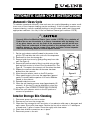
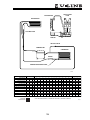
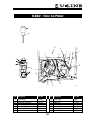
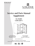
SERVICE AND PARTS
MANUAL
For Product Manufactured With
HFC-134A Freon
CLR60 Clear Ice Maker
U-Line Corporation
U-Line Corporation
8900 North 55th Street
Milwaukee, WI 53223
U-Line Corporation
PO Box 245040
Milwaukee, WI 53224-9540
www.u-line.com
Phone (414) 354-0300 • FAX (414) 354-7905
Service & Parts Tech Lines Phone (800) 779-2547 • FAX (414) 354-5696
R
R
C
R
Service and Parts Manual
NOTES
2
INTRODUCTION
Three generations of pride in quality manufacturing and design improvements are built
into all U-Line products.
We are proud and excited to announce the latest edition to the U-Line family of products,
the CLR60, a 60-pound clear ice maker. We have been developing this product for over
two years and are excited about the quality and features which are unmatched by any
other model in its class. In addition to producing more ice than all other models in its
class, the U-Line CLR60 offers new, patented technology. We have reduced water consumption by 50% per pound of ice compared to some other models on the market. The
CLR60 has the easiest self cleaning process of any model in its class. All clear ice makers require periodic cleaning due to minerals in the water. We have simplified this
process through our electronic control which means ease and convenience for our customers. This model also uses a commercial-grade water circulation pump which is permanently sealed and lubricated, this pump increases the life and performance of the ice
maker. This pump requires no maintenance.
Finally, we have developed an exclusive drain pump for those installations in which a floor
drain is not available. The U-Line P60 pump is a fully submersible, self lubricating pump
that requires no maintenance. It is sealed to prevent water overflow in the event of a
power failure or drain line restriction and is fully integrated into the automatic shut off
feature of the CLR60 with a “quick connect” plug right into the power cord. The P60
pump is available only through U-Line or our Distributors and Dealers.
This service manual contains specific instructions for servicing U-Line’s newest model the
CLR60 - Clear Ice Maker.
3
Service and Parts Manual
NOTES
4
TABLE OF CONTENTS
Introduction . . . . . . . . . . . . . . . . . . . . . . . . . . . . . . . . . . . . . . . . . . . . . . . . . . . .3
Limited Warranty . . . . . . . . . . . . . . . . . . . . . . . . . . . . . . . . . . . . . . . . . . . . . . . .7
Warranty Claims Procedure . . . . . . . . . . . . . . . . . . . . . . . . . . . . . . . . . . . . . . . . .8
Safety Precautions . . . . . . . . . . . . . . . . . . . . . . . . . . . . . . . . . . . . . . . . . . . . . . .9
Leveling and Installation Requirements . . . . . . . . . . . . . . . . . . . . . . . . . . . . . . . .10
Leveling the Unit . . . . . . . . . . . . . . . . . . . . . . . . . . . . . . . . . . . . . . . . . . . .10
Installation Requirements . . . . . . . . . . . . . . . . . . . . . . . . . . . . . . . . . . . . . .10
Gravity Drain Installation . . . . . . . . . . . . . . . . . . . . . . . . . . . . . . . . . . . . . . . . . .11
Connecting a Drain Pump . . . . . . . . . . . . . . . . . . . . . . . . . . . . . . . . . . . . . . . . .12
Automatic Clean Cycle Instructions . . . . . . . . . . . . . . . . . . . . . . . . . . . . . . . . . . .13
Automatic Clean Cycle . . . . . . . . . . . . . . . . . . . . . . . . . . . . . . . . . . . . . . . .13
Interior Storage Bin Cleaning . . . . . . . . . . . . . . . . . . . . . . . . . . . . . . . . . . .13
U-Line CLR Sequence of Operation . . . . . . . . . . . . . . . . . . . . . . . . . . . . . . . . . . .14
Automatic Shut-off . . . . . . . . . . . . . . . . . . . . . . . . . . . . . . . . . . . . . . . . . .14
Thermistor . . . . . . . . . . . . . . . . . . . . . . . . . . . . . . . . . . . . . . . . . . . . . . . . . . .16
Check Procedure w/LED Light on Control Board . . . . . . . . . . . . . . . . . . . . . .16
Low Side Pressure Changes . . . . . . . . . . . . . . . . . . . . . . . . . . . . . . . . . . . .17
Electrical Specifications . . . . . . . . . . . . . . . . . . . . . . . . . . . . . . . . . . . . . . . . . . .18
Compressor Pins . . . . . . . . . . . . . . . . . . . . . . . . . . . . . . . . . . . . . . . . . . .18
Refrigeration System Diagnosis Guide . . . . . . . . . . . . . . . . . . . . . . . . . . . . .19
Ice Thickness Adjustment . . . . . . . . . . . . . . . . . . . . . . . . . . . . . . . . . . . . . . . . .20
Ice Production Rates . . . . . . . . . . . . . . . . . . . . . . . . . . . . . . . . . . . . . . . . . . . .21
Troubleshooting . . . . . . . . . . . . . . . . . . . . . . . . . . . . . . . . . . . . . . . . . . . . . . . .22
Wiring Diagrams . . . . . . . . . . . . . . . . . . . . . . . . . . . . . . . . . . . . . . . . . . . . . . .26
Parts Listing . . . . . . . . . . . . . . . . . . . . . . . . . . . . . . .
CLR60 - Clear Ice Maker Assembly Parts Breakdown
How to Order Replacement Parts . . . . . . . . . . . . .
Fax Parts Order Form . . . . . . . . . . . . . . . . . . . . .
5
. . . . . . . . . . . . . . . . . . .27
. . . . . . . . . . . . . . . .27-29
. . . . . . . . . . . . . . . . . . .30
. . . . . . . . . . . . . . . . . . .31
Service and Parts Manual
Warranty Statement
On 11-1-98, U-Line Corporation modified the warranty provided with our units. We have
significantly improved the coverage of the sealed system in years two through five of the
unit’s life. The new warranty covers parts and labor for one year from the date of purchase. In years two through five, from the date of purchase, the warranty covers parts
and labor for the entire sealed system. The sealed system consists of the compressor,
condenser, evaporator, heat exchanger, dryer, hot gas bypass-valve and all connecting
tubing.
This decision reflects our continuing commitment to strive to maintain the leadership
position within the under counter refrigeration and ice making industry whether that be
through design, product innovation, or enhanced consumer warranties. This decision
reinforces the confidence that U-Line has in the performance and reliability of our products.
Our previous warranty covered parts and labor for one year from the date of purchase
plus four additional years for the compressor, part only.
The new, modified warranty applies only to units shipped after 11-1-98. All units
shipped before 11-1-98 have the previous warranty.
PRODUCTS SHIPPED BEFORE 11-1-98 - Warranty covers parts and labor for one year
from the date of purchase, plus four additional years for the compressor (part only).
PRODUCTS SHIPPED AFTER 11-1-98 - Warranty covers parts and labor for one year
from the date of purchase and covers parts and labor for the entire sealed system for
five years.
DETERMINING SHIP DATES
In order to assure that U-Line is Y2K compliant, we have recently completed a major
computer system modification. The new computer system has lead to changes in the
way we operate in most areas of the company. You’ll soon notice that our packing lists
are different, our invoices are different, our checks are different, and more. The change
that will impact you the most is the change in serial numbers.
With the new computer system, our serial number format has changed. There are some
definite advantages that go with the new format, such as being able to tell the month
and year in which the unit was produced.
The new serial number format breaks the number down into four segments. A typical
serial number is 99 918-06-9351. The first segment -–99, represents the year that the
unit was made. The second segment – 918, represents the shop order number. This
can be a three or four digit number. Order number 918 is assigned for Model 29 Black
–00 units made in June. The third segment – 06 represents the month that the unit was
made. The forth segment – 9351 represents a sequence of numbers that is used internally at U-Line Corporation.
6
LIMITED WARRANTY
U-Line Corporation warrants each U-Line product to be free from defects in materials
and workmanship for a period of one year from the date of purchase; and warrants the
sealed system (consisting of the compressor, the condenser, the evaporator, the hot gas
bypass valve, the dryer and the connecting tubing) in each U-Line product to be free from
defects in materials and workmanship for a period of five years from the date of purchase. During the initial one-year warranty period for all U-Line products U-Line shall: (1)
at U-Line’s option, repair any product or replace any part of a product that breaches this
warranty; and (2) for all Marine, RV and Domestic U-Line products sold and serviced in
the United States (including Alaska and Hawaii) and Canada, U-Line shall cover the labor
costs incurred in connection with the replacement of any defective part. During years
two through five of the warranty period for the sealed system, U-Line shall: (1) repair
or replace any part of the sealed system that breaches this warranty; and (2) for all
Marine, RV and Domestic U-Line products sold and serviced in the United States (including Alaska and Hawaii)and Canada, U-Line shall cover the labor costs incurred in connection with the replacement of any defective part of the sealed system. All other charges,
including transportation charges for replacements under this warranty and labor costs
not specifically covered by this warranty, shall be borne by you. This warranty is extended only to the original purchaser of the U-Line product. The Registration Card included
with the product should be promptly completed by you and mailed back to U-Line.
The following are excluded from this limited warranty: installation charges; damages
caused by disasters or acts of God, such as fire, floods, wind and lightening; damages
incurred or resulting from shipping, improper installation, unauthorized modification, or
misuse/abuse of the product; customer education calls; food loss/spoilage; door and
water level adjustments (except during the first 90 days from the date of purchase);
defrosting the product; adjusting the controls; door reversal; or cleaning the condenser.
If a product defect is discovered during the applicable warranty period, you must promptly notify either the dealer from whom you purchased the product or U-Line at P.O. Box
23220, Milwaukee, Wisconsin 53223 or at 414-354-0300. In no event shall such
notification be received later than 30 days after the expiration of the applicable warranty
period. U-Line may require that defective parts be returned, at your expense, to U-Line’s
factory in Milwaukee, Wisconsin, for inspection. Any action by you for breach of warranty must be commenced within one year after the expiration of the applicable warranty
period.
This limited warranty is in lieu of any other warranty, express or implied, including,
but not limited to any implied warranty of merchantability or fitness for a particular
purpose; provided however, that to the extent required by law, implied warranties are
included but do not extend beyond the duration of the express warranty first set
forth above. U-Line’s sole liability and your exclusive remedy under this warranty is
set forth in the initial paragraph above. U-Line shall have no liability whatsoever for
any incidental, consequential or special damages arising from the sale, use or installation of the product or from any other cause whatsoever, whether based on warranty (express or implied) or otherwise based on contract, tort or any other theory of liability.
Some states do not allow limitations on how long an implied warranty lasts or the exclusion or limitation of incidental or consequential damages, so the above limitations may
not apply to you. This warranty gives you specific legal rights, and you may also have
other rights which vary from state to state.
7
Service and Parts Manual
WARRANTY CLAIMS PROCEDURE
When submitting claims for warranty payment, please follow these guidelines.
You can use any form you would normally use to bill your customer (your own computer
generated form, Narda, USA, etc.).
The model and serial number MUST be on the claims. Claims will not be paid without a
model and serial number.
If you work on more than one unit per service call please submit a separate claim for
each unit.
We track all defects through warranty claims, so please be specific on what the repair
was. If it is a system leak, please specify where the leak was.
Please be sure the claim is legible. If the claim form cannot be read, it will be returned,
unpaid.
U-Line will not cover part or labor claims for the replacement of a complete ice maker
assembly. All ice maker parts are available as replacement parts and are stocked in our
inventory. Remember: we do not pay customer education calls. Door and water level
adjustments are 90 day warranties only.
If you are changing out a unit please supply the model and serial number of both units
(the unit being replaced and the new unit) and the R.A. number.
Occasionally the customer does not return their warranty cards. In this case we use the
date the unit was shipped to our distributor for a beginning warranty date. This may
cause the claim to be rejected for a proof of purchase. If you want to check on a purchase date, you may contact the U-Line Corp. Customer Assurance Department at
1-800-779-2547. This will allow you to get a proof of purchase, if needed, before you
submit the claim.
At U-Line, parts and labor claims are paid separately. Included in labor would be freon
and recovery charges, all other parts are handled by the parts department. We require
that some parts be returned to us, so we may return them to our vendor. It will be
noted on your packing list if we require you to return the part. If a part is to be returned
please include a copy of the packing list and a copy of your claim. If the part was purchased at one of our part distributors, you must handle the part warranty with that company. For labor payment please send a readable copy of your claim to U-Line
Corporation, P.O. Box 245040, Milwaukee WI, 53224-9540, for warranty payment.
8
SAFETY PRECAUTIONS
Do not attempt to service or repair the unit until you have read the entire procedure.
Safety items throughout this manual are labeled with Warning or Caution.
!
!
Warning means that failure to follow this safety statement may result in
extensive product damage, serious personal injury, or death.
!
Caution means that failure to follow this safety statement may result in minor
or moderate personal injury, property or equipment damage.
!
!
DANGER: Risk of child entrapment. Before you throw away an old refrigerator or freezer: Take off the doors, leave shelves in place so that children may
not easily climb inside.
!
!
• Never attempt to repair or perform maintenance on the unit until the electricity has been disconnected.
• Altering, cutting of power cord, removal of power cord, removal of power
plug, or direct wiring can cause serious injury, fire and/or loss of property
and/or life and will void the warranty.
!
• Do not lift unit by door handle.
• Never use an ice pick or other sharp instrument to help speed up defrosting. These instruments can puncture the inner lining or damage the cooling unit.
• Failure to clean the condenser every three months can cause the unit to
malfunction. This could void the warranty.
• Never install the unit behind closed doors. Be sure front grille is free of
obstruction. Obstructing free air flow can cause the unit to malfunction,
and may void the warranty.
9
Service and Parts Manual
LEVELING AND INSTALLATION REQUIREMENTS
The objective of this section is to assist the
service technician in diagnosing problems that
are related to installation and/or leveling.
It is extremely important that the unit is level.
If it is not level, the ice mold will not fill evenly.
This can cause a reduction in ice rate, uneven
sized cubes or water spilling into the storage
area which will cause the ice in the bin to melt
prematurely. See Figure A.
Remember that floors near drains have a tendency to slope towards the drain.
UL307
Figure A
Leveling the Unit
1. Use a level to check the levelness of the icemaker from
front to back and from side to side. See Figure B.
2. If the icemaker is not level, adjust the feet on the corners of the unit as necessary. See Figure C.
UL215
Figure B
3. Check the
levelness
after each
adjustment
and repeat
the previous steps
as necessary until
the unit is
level.
TURN FOOT TO ADJUST
UL205
Figure C
Installation Requirements
• The unit may be built into a cabinet. There is no minimum clearance requirement for
the top, left or right sides of the unit.
• The location must allow enough clearance for water, drain, and electrical connections
in the rear of the unit.
• The location must not obstruct air flow to the front of the unit.
10
GRAVITY DRAIN INSTALLATION
!
Plumbing installation must observe all state and local codes.
These guidelines must be followed when installing drain lines to prevent water from flowing back into the ice maker storage bin and potentially flowing onto the floor causing
water damage:
• Drain lines and fittings must have a 5/8 inch inside diameter
• Drain lines must have a 1 inch drop per 48 inches of run (1/4 inch per foot) and
must not create traps
• The floor drain must be large enough to accommodate drainage from all drains
• Insulate the bin drain line to prevent condensation
If water is backing up into the storage bin, it will be the result of one of the above points
not being followed. Below are examples of gravity drain line installations for your review. If
there must be a trap in the drain line, it is critical that the drain line is vented to assure
proper draining. Without the vent, water will backup until enough pressure builds up to
force the water past the trap. The problem is that the water may backup into the ice bin
before the amount of pressure needed is achieved. Water in the storage bin will cause
the ice in the bin to melt prematurely.
The customer’s complaint will be slow ice production because the ice that has been
made is melting prematurely due to water backing up in the ice bin.
FROM ICE MAKER
TO FLOOR DRAIN
1. Normal Drain.
Pitched from ice maker
at least 1/4" per foot
Proper Drainage
2. With Trap.
Poor drainage.
Water backs up in drain line
Poor Drainage
3. With Trap and Vent.
Vent assures proper drainage
Proper Drainage
UL306
Examples of Gravity Drain Installations
11
Service and Parts Manual
CONNECTING A DRAIN PUMP
!
Plumbing installation must observe all state and local codes. All water and
drain connections MUST BE made by a licensed/qualified plumbing contractor.
Failure to follow recommendations and instructions may result in damage
and/or harm.
If a gravity drain connection is not available, and you have not purchased the CLR60 with
factory installed pump, install the U-Line P60 drain pump in the rear compartment of the
ice maker. The U-Line P60 drain pump is available through your Dealer, or direct from
U-Line with complete installation instructions.
If a gravity drain connection is not available, and you have not purchased the CLR60 with
factory installed pump, U-Line strongly recommends the use of the U-Line P60 drain
pump. If a pump other than the U-Line P60 drain pump is to be used, it must meet the
following specifications:
•
•
•
•
It must be UL listed and have a UL listed, 120 VAC, 3-wire grounded power cord.
Overall maximum outside dimensions of 8-3/4" wide x 5-3/4" deep x 7-3/4" high.
Minimum flow rate of 15 gallons per hour at 10 feet of lift.
It must have a sealed sump which does not allow water leakage in the case of a power
outage, restricted drain or pump failure.
• It must have a check valve in the discharge line to prevent waste water return to the
pump.
• It must have an overflow protection control which will shut off power to the ice maker
in the event of a pump failure.
• Operating temperature range of 50°F to 110°F (10°C to 40°C).
In the event of a power outage, restricted drain or pump failure, the failure to use the
U-Line P60 drain pump or a pump with the above listed specifications, could result in
substantial water leakage and pooling with severe and costly water damage and related
consequential damages and harm.
12
AUTOMATIC CLEAN CYCLE INSTRUCTIONS
Automatic Clean Cycle
To maintain operational efficiency, clean unit every six months (depending on water conditions more or less frequent cleaning may be necessary). If the ice maker requires more
frequent cleaning, consult a qualified plumber to test the water quality and recommend
appropriate treatment. Use only U-Line Ice Machine Cleaner (part number 41978).
!
Use only U-Line Ice Machine Cleaner (part number 41978). It is a violation of
Federal law to use this solution in a manner inconsistent with its labeling. Use
of any other cleaner can ruin the finish of the evaporator and will void the warranty. Read and understand all labels printed on the package before use. Ice
machine cleaner is used to remove Lime scale and other mineral deposits.
Refer to the following steps for mineral deposit removal.
1. Set the cycle selector switch (located in the center of the
grille) to OFF and allow the ice to melt off of the evaporator.
2. Remove all ice from the storage bin.
3. Remove inside front cover by gently pulling away from sidewall. See Figure A.
4. Remove the overflow tube by lifting it up while using a slight
back and forth motion to loosen it from the drain hole. See
Figure B. The water in the reservoir will flow down the drain.
5. Replace the overflow tube after all the water has been
drained from the reservoir.
6. Move the cycle selector switch to the CLN position.
7. When water begins to flow over the evaporator, (approximately 3 minutes) add one packet of U-Line Ice Machine
Cleaner to the reservoir.
8. Reinstall inside front cover.
9. When the self cleaning process stops (approximately 45
minutes). At this time, it may be desirable to clean the
storage bin. (See INTERIOR STORAGE BIN CLEANING)
10.Move the cycle selector switch to the ICE position to
resume ice production.
Interior Storage Bin Cleaning
FRONT COVER
U
U•LINE
Figure A
UL208
OVERFLOW
Figure B
UL209
1. Disconnect power from the ice maker.
2. Remove any ice from the storage bin.
3. Wipe down the storage bin with a solution of non-abrasive mild soap or detergent and
warm water. Rinse with clean water. Sanitize the bin with a solution of 1 tablespoon
of bleach and 1 gallon of water. Rinse thoroughly with clean water.
4. Check that all drain connections are in place.
5. Reconnect power to the unit.
13
Service and Parts Manual
U-LINE CLR60 SEQUENCE OF OPERATION
On initial start-up or restart (closing of bin thermostat), the toggle switch is in the ice
position:
1. The water solenoid valve and hot gas solenoid valve are opened (energized) for 180
seconds (3 minutes). This ensures that the icemaking cycle starts with fresh water,
and that the refrigerant pressures are equalized prior to compressor start-up.
2. The compressor starts 175 seconds after the hot gas solenoid valve and water solenoid valves are opened.
3. The water pump and condenser fan motor are energized, and the hot gas solenoid
valve and water solenoid valves are de-energized (closed) five seconds after the compressor starts. The unit is now in the freeze cycle.
4. As the water pump circulates the water, an even flow is directed across the evaporator and into each cube cell, where it freezes. As the water freezes, gravity causes
any sediment to drop into the water trough and not becoming imbedded in the ice.
This gives a clearer cube with low mineral content.
5. The control system automatically determines the length of the freeze cycle by monitoring the temperature of the refrigeration system “high side” using a thermistor.
6. One minute prior to finishing the determined freeze cycle, the control determines the
length of the harvest cycle by again monitoring the temperature at the thermistor.
7. When the freeze cycle is completed, the control de-energizes the water pump and
the condenser fan motor. The compressor remains running during the harvest cycle.
The control then energizes the hot gas solenoid valve and water solenoid valve for the
duration of the harvest cycle. The hot refrigerant gas warms the evaporator causing
the cubes to slide, as a sheet, off the evaporator and into the storage bin. At the
same time, the water trough is being purged with fresh water.
8. At the conclusion of the harvest cycle, the machine returns to a new freeze cycle. The
compressor continues to run. The water pump and condenser fan motor are energized.
The hot gas solenoid valve and water solenoid valves are de-energized (closed).
Automatic Shut-off
The ice machine shut-off is controlled by the level of ice in the ice storage bin. When the
bin is full, ice contacts the bin thermostat bulb holder, which senses the cool temperatures, then opens which stops the ice machine. The ice machine remains off until
enough ice has been removed from the bin or has melted that the ice cubes are
no longer in contact with the bin thermostat bulb holder. This causes the bin thermostat
to warm and close, restarting the ice machine. When the ice machine restarts, it
returns to the start-up sequence (steps 1, 2, and 3 above).
14
CIRCULATION
PUMP
EVAPORATOR
EVAPORATOR
ACCUMULATOR
WATER
TROUGH
HOT GAS VALVE
COMPRESSOR
CONDENSER
DRYER
THERMISTOR SENSING POINT
UL304
CYCLE DESCRIPTION
TIME (MINUTES)
INITIAL START-UP
1
2
FREEZE CYCLE
3
4
5
HARVEST CYCLE
6
7
8
9
10
11
12
13
14
15
16
17
18
19
WATER FILL VALVE
HOT GAS VALVE
WATER CIRCULATION PUMP
COMPRESSOR
CONDENSER FAN
ENERGIZED
NOTE: THE FREEZE / HARVEST CYCLE TIMES WILL VARY DUE TO OPERATING CONDITIONS.
UL305
NON-ENERGIZED
15
Service and Parts Manual
THERMISTOR
The thermistor senses the refrigeration system “High side” temperature. This is used in
conjunction with the control board to determine the length of the freeze and harvest
cycles.
Thermistors generally fail due to moisture or physical damage. U-Line “high side” thermistors are encased in a specially-designed, moisture-sealed aluminum block. The thermistor is also mounted to the “high side” or “dry” portion of the refrigeration system. This
eliminates physical damage and moisture concerns.
Check Procedure w/LED Light on Control Board
The LED light on the control board serves three functions.
1. Steady light 2. Slow flash -
3. Rapid flashing -
The control board has power to it. There are no sensing
problems and operation is normal.
The control board has detected a sensor problem. This will
happen if the thermistor’s plug is disconnected from the
control board. This will also happen if the thermistor fails
open.
This indicated that the control board is receiving a high heat
signal from the thermistor. This can be caused by a dirty
condenser, inadequate air flow (unit installed behind closed
doors), failed condenser fan motor, etc.
In both the slow flash and rapid flashing situations, the unit will stop operation.
-2
-3
-5
-4
-1 0 1
2
3
4
5
LED Light
UL301
16
Low Side Pressure Changes
The chart above shows the low side pressure changes through the cycles of a CLR60 unit.
It shows that during a harvest cycle, the low side pressures climb to nearly 60 psig. When
the freeze cycle starts, the pressure quickly drops to approx. 17 psig and throughout the
freeze cycle it continues to slowly drop to approx. 7 psig just before the harvest cycle.
This unit was operating in a 75° farenheit ambient temperature and the incoming
water temperature was 50° farenheit.
If a unit is operating in conditions other than these, the low side pressures will be different. A unit operating in a warmer ambient environment or using warmer water will
have higher pressure readings. A unit in a cooler ambient environment or using cooler water will have lower pressure readings.
17
Service and Parts Manual
ELECTRICAL SPECIFICATIONS
S
R
C
STARTING
RELAY
3/4" OVERLOAD
PROTECTION
UL303
Compressor Pins
To measure start winding resistance, measure across the C - S pins.
To measure run winding resistance, measure across the C - R pins. These pins should
never measure any resistance to ground. This would indicate a shorted compressor.
Specifications:
FF7.5HBK Compressor Start Winding
FF7.5HBK Compressor Run Winding
12.0 OHMS
2.9 OHMS
CLR60 Water Valve Coil Resistance
280 OHMS
Bypass Coil Resistance
380 OHMS
Pump Motor Winding Resistance
71.5 OHMS
18
19
Suction
Pressure
Normal
Higher than
normal
Lower than
normal
Somewhat
lower than
normal-in
vacuum
In deep
vacuum
0 PSIG
to
25" vacuum
System
Condition
Normal
Overcharge
Undercharge
Partial
Restriction
Complete
Restriction
No
Gas
Room
temperature
(cool)
Room
temperature
(cool)
Warm - near
room
temperature
Warm - near
room
temperature
Very cold
may frost
heavily
Slightly below
room
temperature
Suction
Line
Cool
to
hot
Room
temperature
(cool)
Very hot
Hot
Slightly warm
to hot
Very hot
Compressor
Discharge
Room
temperature
(cool)
Room
temperature
(cool)
Top passes
warm Lower passes
cool
(near room
temperature)
due to liquid
Warm
Hot to warm
Very hot
Condenser
Room
temperature
(cool)
Room
temperature
(cool)
Room
temperature
(cool) or
colder
Warm
Cool
Warm
Capillary
Tube
Cold
Cold
Evaporator
No
refrigeration
No
refrigeration
Extremely cold
near inlet Outlet
below room
temperature
backing up
Extremely cold
near inlet Outlet
below room
temperature
Refrigeration System Diagnosis Guide
Lower than
normal
Lower than
normal
Lower than
normal
Lower than
normal
Higher than
normal
Normal
Wattage
Service and Parts Manual
ICE THICKNESS ADJUSTMENT
The ice thickness control is factory set to maintain
an ice bridge of 1/16" to 1/8". A dimple in each
cube is normal. This size cube will break apart from
the slab easily as it falls into the ice bin. A fuller
cube, with less of a dimple, can be achieved by
adjusting the cube size. This will result in a thicker
ice bridge. As the ice bridge becomes thicker, the
tendency for the cubes to stay together as a slab
increases.
ICE BRIDGE SHOULD BE
1/16 - 1/8 INCH THICK
A DIMPLE IN EACH
CUBE CELL IS NORMAL
UL250
If an adjustment is needed, perform the following steps:
!
!
Do not touch electrical wires. Disconnect power to the ice maker before
making any ice thickness adjustments.
1. Disconnect power from the unit.
2. Remove front access panel (2 screws).
3. Locate the ice thickness adjustment dial on the control board (See below).
-5
-2
-3
-4
-1 0 1
5
2
4
3
ICE THICKNESS
ADJUSTMENT
DIAL
-2
-3
-5
-4
-1 0 1
2
3
4
5
DIAL IS FACTORY
SET TO +1
UL318A
NOTE
Ice thickness adjustment dial should be turned only one increment at a time.
Allow the unit to stabilize for 24 hour hours before making further adjustments.
4. Turn ice thickness adjustment dial clockwise for a thicker ice bridge or counterclockwise for a thinner ice bridge.
5. Reinstall front access panel.
6. Reconnect power.
20
ICE PRODUCTION RATES
Ambient Temp/Water Temp degrees F
Approximate Ice Production (lbs/day)
50/50
60
60/50
60
70/50
58
80/50
54
90/70
47
100/70
40
NOTE
These characteristics will vary depending on operating conditions, condenser
cleanliness, installation, and application.
21
Service and Parts Manual
TROUBLESHOOTING
!
!
NEVER attempt to repair or perform maintenance on the unit until the main
electrical power has been disconnected.
1. Unit Does Not Operate (With drain pump; light on control board is not illuminated)
Cause
■ No electrical power to the unit
■ Rocker switch set incorrectly
■ Drain tube is kinked or obstructed
■ Bad pump. Diagnose by bypassing
the pump. Pull both pink wires from
control board and jump the two
terminals together. If unit starts up,
then the pump is bad.
■
■
■
■
Remedy
Make sure unit is plugged in and outlet
has power
Check switch wiring. Set to “ICE”
Clear the tubinga
Change pumpb
a: If water cannot drain from pump, unit will shut down due to safety design of pump.
b: Jumping the two terminals on control board together with a jumper wire will eliminate
pump from the circuit.
2. Unit Does Not Operate (Without drain pump; light on control board is not illuminated)
Cause
■ No power to unit
■
Remedy
Jumper plug off power cord
3. Unit Does Not Operate And Light On Control Board is Illuminated
Cause
■ Bad bin thermostat
■ Bin thermostat set incorrectly
■
■
Remedy
Replace bin thermostatc
Set bin thermostat at the 10:00 position
c: The unit is falsely sensing a full bin.
4. No Ice Production
Cause
■ No water supplied to unit
■
■ Stand pipe not inserted in water trough ■
■ Re-circulating pump is defective
■
22
Remedy
Check that water is connected and
turned on
Insert stand pipe securely into water
trough
Replace re-circulating pump
5. Low Ice Production
Cause
■ High ambient temperatures around unit ■
■ Deposit build-up on evaporator grid
■
■ Ice thickness dial set incorrectly
■ Dirty condenser coil
■
■
Remedy
Lower ice rate is normal with high
ambient temperatures
Run the unit through a clean cycle. Use
only U-Line Ice Machine Cleaner
Adjust ice thickness dial accordingly
Clean condenser coil
NOTE: Light on control board will indicate if condenser is too dirty. A rapid flash of light
indicates high heat conditions which could be caused by either an inadequate air flow or
a dirty condenser.
6. Will Not Eject Ice (Water Frozen)
■
■
■
■
Cause
Bin thermostat set incorrectly
Wiring plug off of bypass valve coil
Defective bypass valve
Deposit build-up on evaporator grid
■
■
■
■
Remedy
Set bin thermostat at 10:00 position
Re-install plug
Replace bypass valve
Run unit through the clean cycle. Use
only U-Line Ice Machine Cleanere
e: If scale or mineral deposits accumulate on grid, cubes will not fall freely.
7. Ice Is Slow To Release From Evaporator
Cause
■ Deposit build-up on evaporator grid
■
■ Unit not level
■
Remedy
Run unit through the clean cycle. Use
only U-Line Ice Machine Cleaner.
Level unit for even water flowf
f: Uneven water flow will reduce ice rate and cause water to spill in ice bin.
8. Will Not Fill With Water
Cause
■ No stand pipe in water trough
■ Water valve is defective
■ Water solenoid unplugged
or wire to solenoid has internal break
■
■
■
Remedy
Install stand pipe
Replace valve
Repair wiring defect
■
■
Remedy
Set bin thermostat to the 10:00 position
Insert bulb inside aluminum sensor tube
9. Continuous Ice Production
Cause
■ Bin thermostat set too cold
■ Bin thermostat sensing bulb out
of alignment
■ Bin thermostat stuck in closed position
■ Ice slab too thick
■
■
Replace bin thermostat
Set ice thickness adjustment dial to a
lower settingg
g: If cubes release from grid and are too thick, cubes might not make contact with
sensor tube (inside of bin) therefore bin thermostat would never be satisfied.
23
Service and Parts Manual
10. Low (or no) Ice Production
Cause
■ Dirty condensing coil (Control board
light shows rapid flash)
■ Stalled condenser fan blade (Control
board light shows a rapid flash)
■ No water in water trough
■ Bypass valve stuck in open position
■ Ice forms on a portion of evaporator grid
■
Remedy
Clean condensing coil
■
Free up the blade or replace fan motor
■
■
■
Install stand pipe securely in trough
Replace bypass valve
Check unit for system undercharge or leak
NOTE: See chart of suction pressures
in manual.
11. Poor Ice Quality (soft or unclear cubes)
Cause
■ Poor incoming water quality
■ Deposit build-up on evaporator grid
■
■
■ Water splashing on cubes
■
Remedy
Consult a plumber
Run the unit through a clean cycle. Use
only U-Line Ice Machine Cleaner
Adjust water flow above evaporator
12. Unit Not Freezing (compressor and fan operating)
Cause
■ Little or no cooling
■ Bypass valve stuck in open position
■
■
Remedy
Check sealed system for leak or restriction
NOTE: See chart of suction pressures
in manual.
Replace bypass valve
13. Unit Produces Shallow or Incomplete Cubes or the Ice Fill Pattern on the Grid is
Incomplete
Cause
■ Low water level
■
■ Low water pressure
■
■ Unit is not level
■ Operating unit without back or
front panel
■ Bad thermister
■ Bad control board
■
■
Remedy
Check that standpipe is fully seated
inside water trough
Check water pressure into water valve
(pressure should be 20 to 120 psi).
Level unit to assure even water flowh
Install back or front paneli
■
■
Replace thermister
Replace control board
h: uneven water flow will reduce ice rate and cause incomplete cubes. See Leveling
Instructions in manual.
i: the unit will harvest ice according to temperatures of tubing at condensing coil.
Increased air flow will give the thermister false information. This info could cause the
ice to eject prematurely.
14. Not Freezing Compressor Not Running / Fan Operating
Cause
■ Bad overload (open)
■ Bad compressor
■
■
24
Remedy
Replace overload
Replace compressor
15. Not Freezing (compressor and fan not operating)
Cause
■ No electrical power to unit
■
■ Rocker switch defective or wired
incorrectly
■
IF UNIT HAS P-60 PUMP
Cause
■ Drain tube kinked or obstructed
■ Bad pump. Diagnose by bypassing
the pump. Pull both pink wires from
control board and jump the two
terminals together. If unit starts up,
then the pump is bad.
■ Open wire in wiring harness
■
■
■
Remedy
Make sure unit is plugged in and outlet
has power
Make sure switch is wired correctly and
set in “ICE” position
Remedy
Clear the tubingj
Change pumpk
Trace defective wire and repair or
replace parts accordingly
j: If water cannot drain from pump, unit will shut down due to safety design of pump.
k: Jumping the two terminals on control board together with a jumper wire will eliminate
pump from the circuit.
16. Water Leak Under Unit
Cause
■ Incoming water supply line leaking
■
■ Fill tube leaking
■ Bin spout is cracked or mis-formed
■
■
17. Water In Ice Bin
Cause
■ Bin drain kinked or restricted
■ External drain is restricted
■ Bad pump
■
■
■
Remedy
Clear drain of obstruction or kink
Clear restriction
Replace pump
18. Water Will Not Stop Filling
Cause
■ Water solenoid stuck in open position
■ Open relay on control board
■
■
Remedy
Replace water valve
Replace control board
Remedy
Make sure brass connection is screwed
tight to valve and threaded correctly
Tighten fill tube connection to water line
Unit not repairable. Contact U-Line
tech line for assistance.
NOTE: A defective relay on control board would cause both the water valve and reversing
valve to stay open, therefore, this failure would not allow the unit to freeze.
19. Unit Noisy
Cause
■ Fan motor not secured to bracket
■ Fan blade bent
■ Vibration from refrigerant lines
■ Obstruction in fan blade
■
■
■
■
Remedy
Tighten motor
Realign or replace blade
Secure tubing
Remove obstruction
REPLACEMENT PARTS: Use only genuine U-Line replacement parts. The use of non
U-Line parts can reduce ice rate, cause water to overflow from ice maker mold, damage the unit, and may void the warranty.
25
Service and Parts Manual
CLR60 WIRING DIAGRAM
WITH U-LINE P60 DRAIN PUMP
BLACK
WHITE
GREEN
PINK
U-LINE P60 WASTE WATER PUMP
L2(N)
GREEN
BLACK
SEE- WITH PUMP
L1
WHITE
WHITE
BLACK
PINK
THERMISTOR
GREEN
COMPRESSOR
PINK
GREEN
CONTROL BOARD
BLACK
FAN
BLACK
BLACK
WHITE
WHITE
RELAY
YELLOW
OVERLOAD
WATER PUMP
TIME ADJ.
ICE
GREEN
RED
OFF
CLEAN
YELLOW
LIGHT
WHITE
1
RED
BROWN
WHITE
HOT GAS
SOLENOID
2
PURPLE
WHITE
TRANS
WHITE
BIN THERMOSTAT
WATER INLET
SOLENOID
BLACK
GREEN
FUSE
CLOSED
BETWEEN
CLEAN
BLACK
PURPLE
ICE
BLACK
BROWN
PURPLE
3
BROWN
RED
SWITCH
POSITION
BROWN
BLACK
BLACK
UL302
26
CLR60 - Clear Ice Maker
7
11
8
12
15
16
17
1
13
3
16
21
14
10
18
2
4
9
4
Top Pivot Screw - 41785 - Specify Color
Bottom Pivot Screw - 41747 - Specify Color
Item Description
1
2
3
4
5
6
7
Drain Tube (Clear)
Rocker Switch CL60
Water Valve
Water Line
Nut Sleeve Assembly
90 Degree Brass
Hinge Top
Hinge Top, Stainless Steel
8 Evaporator Assembly
9 Leveling Leg
10 Hinge Bottom
Hinge Bottom, Stainless Steel
5
6
CLR60A
Part No.
Item Description
2820-S
2285
2716
404-CLR60
41254
41826
11697-ST*
1848A-SS
2276-S
41319
11695-S*
11 Door Handle
Door Handle, Stainless Steel
12 Door Gasket Upper
13 Door Gasket Lower
14 Grille
15 Door Assembly
16 Bin Thermostat
17 Bin Thermostat Tube
18 Control Board
21 Lower Front Panel
** Hinge Plate Top (Not Shown)
** Hinge Plate Bottom (Not Shown)
11624-1-S-BLK
*Please indicate color.
**Stainless Steel Only.
27
Part No.
31489-2**
42021
31625*
31626*
31543*
CLR60-DOOR*
2708
11841
2707-S
11816*
1847-1-SS
1847-2-SS
Service and Parts Manual
CLR60 - Clear Ice Maker
4
6
9
5
1
8
2
3
10
7
Parts Not Shown
Part No.
U-Line Specified CLR60 Cleaner
(Six applications per order)
U-Line Specified Drain Pump
41978
Item Description
1
2
3
4
5
Pump
Pre-formed Tube (White)
Water Trough
Water Disp. Receptacle
Stand Pipe
CLR60B
P60
Item Description
Part No.
31613
31615-S
11813
11812
31619
6
7
8
9
10
28
Well Nut
Cover (Front)
Pump Cover (Rear)
Hook for Ice Scoop
Ice Scoop
Part No.
41979
11868
11893
42011
31614
CLR60 - Clear Ice Maker
2
13
8
1
5
12
4
10
15
6
7
11
Item Description
1
2
4
5
6
7
8
Compressor
Bypass Valve Assembly
Condenser Assembly
Heat Exchanger Assembly
Condenser Fan Motor
Condenser Fan Blade
Wire
9
14
CLR60C
Item Description
Part No.
5406-S
2749-S60
2269-S
2725-S
5300
5303
2284
9
10
11
12
13
14
15
29
Power Cord
Copper “T”
Thermistor
Drain Tubing
Back Panel
Drier
Overload/Relay
Part No.
2282
2296-S
2709-S
31617-S
41802
2693
5427
Service and Parts Manual
PARTS LISTING
How to Order Replacement Parts
1. Locate the illustration(s) for the model you are servicing.
NOTE
Some models may have more than one illustration based on Serial Number
breaks.
2. Refer to the area where the desired part would be installed, locate the part and note
the item number assigned to it.
3. Locate the item number in the left column of the parts listing which is below the product illustration. Note the full description and the corresponding part number. If this is
for a warranty unit, please indicate so.
4. When ordering parts, it will be necessary to supply us with Model Number, Serial
Number, Part Number, Part Description and in some cases Color or Voltage.
5. U-Line requires the return of parts listed below if replaced under warranty:
•
•
•
•
Pumps
Control Boards
Evaporator Assemblies
Fan Motors
•
•
•
•
Bin Thermostat
Solenoid Valves
Bypass Solenoids
Compressors (during the first two years only)
All warranty parts will be shipped at no charge as long as warranty status has been confirmed. We require that some parts be returned to us, so we may return them to our
vendor. It will be noted on your packing list if we require you to return a part or if you
may field scrap it. When returning parts please enclose a copy of your packing list and a
copy of your labor claim, showing the model and serial number.
Our warranty records may not match the customers information. In which case a proof
of purchase will be required. If you do not have the proof of purchase at the time the
order is placed the part will be sent net 15 days (COD if you don’t have an open account
with U-Line Corporation). When the proof of purchase is provided we will credit your
account (a check will be sent if the part was sent COD).
6. Parts may be ordered by FAX or phone.
FAX Number (414) 354-7905
Phone Number (414) 354-0300 or (414) 354-7885; press 3
Toll Free 1-800-779-2547
To expedite parts shipments, FAX all parts orders to: (414) 354-7905. Copy the FAX
Parts Order Form, located in the back of this manual, when placing an order.
REPLACEMENT PARTS: Use only genuine U-Line replacement parts. The use of non
U-Line parts can reduce ice rate, cause water to overflow from ice maker mold, damage
the unit, and may void the warranty.
30
FAX PARTS ORDER FORM
FAX # 414-354-7905
Account# ______________________________________
Ship to: ______________________________________
Bill to: ________________________________________
______________________________________________
______________________________________________
______________________________________________
______________________________________________
Attention:
Date: __________________________________________
P.O. __________________________________________
Phone#________________________________________
Fax#__________________________________________
PART#
COLOR
QTY
DESCRIPTION
MODEL
SERIAL
NUMBER
UNIT IN
WARRANTY?
SPECIAL INSTRUCTIONS:
All part shipments will be sent ground delivery.
We have air shipment available at an additional cost to you.
Next Day Air
2nd Day Air
3 Day Select
If you do not have an open account with us your order will be shipped C.O.D.
COMMENTS: ____________________________________________________________________________________
________________________________________________________________________________________________
Authorized By ________________________________________________
P.O. Box 245040
Milwaukee, WI 53224-9540
Phone 414.354.0300
FAX 414.354.7905
Printed in U.S.A. – March 2000
P/N 42002