1
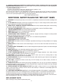
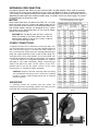
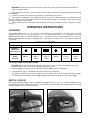
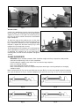
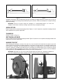
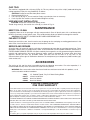
ESPAÑOL: PAGINA 11
FRANÇAISE : PAGE 23
Instruction
Manual
14" “Dry-Cut” Metal
Cutting Saw
MODEL 1410
To learn more about Porter-Cable
visit our website at:
http://www.porter-cable.com
IMPORTANT
Please make certain that the person who is to
use this equipment carefully reads and
understands these instructions before starting
operations.
The Model and Serial No. plate is located on the main
housing of the tool. Record these numbers in the
spaces below and retain for future reference.
Model No. _____________________________________
Type __________________________________________
Serial No.______________________________________
Copyright © 2000 Porter-Cable Corporation
Part No. 896182-009
SAFETY INSTRUCTIONS
GROUNDING INSTRUCTIONS
GROUNDED OUTLET BOX
WARNING:
THIS
TOOL
SHOULD
BE
GROUNDED WHILE IN USE TO PROTECT THE
OPERATOR FROM ELECTRIC SHOCK. The tool
is equipped with an approved three-conductor
cord and three-prong grounding type plug to fit
the proper grounding type receptacle. The green
(or green and yellow) conductor in the cord is the
grounding wire. Never connect the green (or green
and yellow) wire to a live terminal.
CURRENT
CARRYING
PRONGS
GROUNDING PRONG IS
LONGEST OF THE 3 PRONGS
If your unit is for use on less than 150 Volts, the
power cord is equipped with a plug that has two
flat, parallel current-carrying prongs and one
longer, round or “U”-shaped, ground prong which
requires a mating 3-conductor grounded type
receptacle, as shown in Fig. 1.
Fig. 1
GROUNDED OUTLET BOX
GROUNDING MEANS
ADAPTER
An adapter, shown in Fig. 2, is available for
connecting 3-prong grounding type plugs that are
used on units less than 150 Volts to 2-prong
receptacles. THIS ADAPTER IS NOT ALLOWED
IN CANADA. The green colored rigid ear, lug, etc.,
must be connected to a permanent ground such
as a properly grounded outlet box, as shown in
Fig. 2.
Fig. 2
If your unit is for use on 150 to 250 Volts, the
power cord is equipped with a plug that has two
flat current carrying prongs in tandem, and one
round or “U”-shaped, longer ground prong, as
shown in Fig. 3. This plug is used only with the
proper mating 3-conductor grounding type
receptacle, as shown in Fig. 3. No adapter is
available for this type plug.
GROUNDED OUTLET BOX
CURRENT
CARRYING
PRONGS
WARNING: IN ALL CASES, MAKE SURE THE
RECEPTACLE IN QUESTION IS PROPERLY
GROUNDED.
NEVER REMOVE GROUNDING PRONG FROM
POWER PLUG.
GROUNDING PRONG IS
LONGEST OF THE 3 PRONGS
Fig. 3
EXTENSION CORDS
Use only three-wire extension cords which have three-prong grounding type plugs and three-pole receptacle
which accept the tool’s plug. Replace damaged or worn cord immediately. DO NOT ATTEMPT TO REPAIR
POWER CORD.
2
IMPORTANT SAFETY INSTRUCTIONS
WARNING: When using electric tools, basic safety precautions should always be followed to reduce
the risk of fire, electric shock and personal injury, including the following:
READ AND FOLLOW ALL INSTRUCTIONS.
There are certain applications for which this tool was designed. Porter-Cable strongly recommends that this tool
NOT be modified and/or used for any application other than for which it was designed. If you have any questions
relative to its application DO NOT use the tool until you have written Porter-Cable and we have advised you.
Technical Service Manager
Porter-Cable Corporation
4825 Highway 45 North,
Jackson, TN 38305
1. FOR YOUR OWN SAFETY, READ INSTRUCTION MANUAL BEFORE OPERATING THE TOOL. Learn the
tool’s application and limitations as well as the specific hazards peculiar to it.
2. KEEP GUARDS IN PLACE and in working order.
3. GROUND ALL TOOLS. If tool is equipped with three-prong plug, it should be plugged into a three-hole
electrical receptacle. If an adapter is used to accommodate a two-prong receptacle, the adapter plug must be
attached to a known ground. Never remove the third prong.
4. REMOVE ADJUSTING KEYS AND WRENCHES. Form habit of checking to see that keys and adjusting
wrenches are removed from tool before turning it “ON”.
5. KEEP WORK AREA CLEAN. Cluttered areas and benches invite accidents.
6. DON’T USE IN DANGEROUS ENVIRONMENT. Don’t use power tools in damp or wet locations, or expose
them to rain. Keep work area well-lighted.
7. KEEP CHILDREN AND VISITORS AWAY. All children and visitors should be kept a safe distance from work
area.
8. MAKE WORKSHOP CHILDPROOF – with padlocks, master switches, or by removing starter keys.
9. DON’T FORCE TOOL. It will do the job better and be safer at the rate for which it was designed.
10. USE RIGHT TOOL. Don’t force tool or attachment to do a job for which it was not designed.
11. WEAR PROPER APPAREL. No loose clothing, gloves, neckties, rings, bracelets, or other jewelry to get
caught in moving parts. Nonslip footwear is recommended. Wear protective hair covering to contain long hair.
12. ALWAYS USE SAFETY GLASSES. Wear safety glasses (must comply with ANSI Z87.1). Everyday
eyeglasses only have impact resistant lenses; they are not safety glasses. Also use face or dust mask if cutting
operation is dusty.
13. SECURE WORK. Use clamps or a vise to hold work when practical. It’s safer than using your hand and
frees both hands to operate tool.
14. DON’T OVERREACH. Keep proper footing and balance at all times.
15. MAINTAIN TOOLS IN TOP CONDITION. Keep tools sharp and clean for best and safest performance.
Follow instructions for lubricating and changing accessories.
16. DISCONNECT TOOLS before servicing and when changing accessories such as blades, bits, cutters, etc.
17. USE RECOMMENDED ACCESSORIES. The use of improper accessories may cause hazards.
18. AVOID ACCIDENTAL STARTING. Make sure switch is in “OFF” position before plugging in power cord.
19. NEVER STAND ON TOOL. Serious injury could occur if the tool is tipped or if the cutting tool is accidentally
contacted.
20. CHECK DAMAGED PARTS. Before further use of the tool, a guard or other part that is damaged should
be carefully checked to ensure that it will operate properly and perform its intended function - check for
alignment of moving parts, binding of moving parts, breakage of parts, mounting, and any other conditions that
may affect its operation. A guard or other part that is damaged should be properly repaired or replaced.
21. DIRECTION OF FEED. Feed work into a blade or cutter against the direction of rotation of the blade or
cutter only.
22. NEVER LEAVE TOOL RUNNING UNATTENDED. TURN POWER OFF. Don’t leave tool until it comes to a
complete stop.
23. DRUGS, ALCOHOL, MEDICATION. Do not operate tool while under the influence of drugs, alcohol or any
medication.
24. MAKE SURE TOOL IS DISCONNECTED FROM POWER SUPPLY while motor is being mounted,
connected or reconnected.
3
25. WARNING: SOME DUST CREATED BY POWER SANDING, SAWING, GRINDING, DRILLING, AND OTHER
CONSTRUCTION ACTIVITIES contains chemicals known to cause cancer, birth defects or other reproductive
harm. Some examples of these chemicals are:
• lead from lead-based paints,
• crystalline silica from bricks and cement and other masonry products, and
• arsenic and chromium from chemically-treated lumber.
Your risk from these exposures varies, depending on how often you do this type of work. To reduce your exposure
to these chemicals: work in a well ventilated area, and work with approved safety equipment, such as those dust
masks that are specially designed to filter out microscopic particles.
SAVE THESE INSTRUCTIONS
ADDITIONAL SAFETY RULES FOR “DRY-CUT” SAWS
1. WARNING: Do not operate your dry-cut saw until it is completely assembled and installed according to the
instructions.
2. IF YOU ARE NOT thoroughly familiar with the operation of “dry-cut” metal cutting machines, obtain advice
from your supervisor, instructor or other qualified person.
3. WEAR SAFETY GOGGLES, HEARING PROTECTION, face shield, respirator, body apron, head covering,
safety shoes, and long tight-fitting sleeves.
4. USE ONLY RECOMMENDED carbide tipped metal cutting blades, rated at 1500 RPM or higher.
5. TIGHTEN ARBOR SCREW and all clamps before operating.
6. MAKE SURE spindle lock is disengaged before operating.
7. KEEP HANDS OUT of the path of saw blade.
8. SECURE WORK PIECE PROPERLY. Work should be straight and firmly clamped to avoid possible
movement and pinching as the cut nears completion.
9. PROVIDE ADEQUATE SUPPORT to the sides of the saw table for long workpiece.
10. NEVER CUT ANYTHING FREEHAND.
11. NEVER REACH behind or beneath the blade.
12. MAKE SURE the blade has come to a complete stop before removing or securing workpiece, or changing
workpiece angle.
13. MAKE SURE the inside surfaces of the blade flanges as well as the sides of the blade are free from any
foreign matter.
14. ALWAYS CHECK THE BLADE for cracks or other damage before operation. Replace cracked or damaged
blade immediately.
15. MAKE SURE blade is not contacting workpiece before switch is turned on.
16. ALLOW THE MOTOR to come up to full speed before starting cut.
17. AFTER TURNING MACHINE ON, gently lower the blade to engage workpiece, then slowly increase
pressure as required to produce the least amount of “sparking”.
18. IMPORTANT: After completing the cut, release power switch and wait for coasting blade to stop
completely, before returning saw to the raised position.
19. NEVER OPERATE the machine in an area with flammable solids, liquids or gases. Sparks or hot fragments
could cause a fire or explosion.
20. THIS TOOL is designed for ferrous metals only. DO NOT attempt to cut wood, masonry, aluminum or
magnesium with this tool.
21. SHOULD ANY PART of your machine be missing, damaged or fail in any way, or any electrical component
fail to perform properly, shut-off switch and remove plug from power supply outlet. Replace missing, damaged
or failed parts before resuming operation.
22. NEVER CONFINE THE PIECE BEING CUT OFF. Never hold it, clamp it, touch it, or use length stops
against it while the blade is turning. It must be free to move sideways. If confined, it could wedge against the
blade and be thrown violently.
23. ADDITIONAL INFORMATION regarding the safe and proper operation of this product is available from
the National Safety Council, 444 N. Michigan Avenue, Chicago, IL 60611, in the Accident Prevention Manual
for Industrial Operation and also in the Safety Data Sheets provided by the NSC. Please also refer to the
American National Standard Institute ANSI B11.10 Safety Requirements for the Construction, Care and Use of
Metal Sawing Machines and the U.S. Department of Labor OSHA 1910 Regulations.
REPLACEMENT PARTS
When servicing use only identical replacement parts.
4
EXTENSION CORD SELECTION
Use proper extension cord. Make sure your extension cord is in good condition. When using an extension
cord, be sure to use one heavy enough to carry the current your product will draw. An undersized cord will
cause a drop in line voltage resulting in loss of power and overheating. Fig. 3A shows the correct size to use
depending on cord length and nameplate ampere rating. If in doubt, use the next heavier gage. The smaller
the gage number, the heavier the cord.
RECOMMENDED EXTENSION CORD SIZES FOR
MOTOR
USE WITH STATIONARY ELECTRIC TOOLS
Many Porter-Cable tools will operate on either D.C., or single
phase 25 to 60 cycle A.C. current and voltage within plus or
minus 5 percent of that shown on the specification plate of the
tool. Several models, however, are designed for A.C. current
only. Refer to the specification plate on your tool for proper
voltage and current rating.
CAUTION: Do not operate your tool on a current on
which the voltage is not within correct limits. Do not
operate tools rated A.C. only on D.C. current. To do so
may seriously damage the tool.
POWER CONNECTIONS
A separate electrical circuit should be used for your tools. This
circuit should not be less than #12 wire and should be protected
with a 20 Amp time lag fuse. If an extension cord is used, use
only 3-wire extension cords which have 3-prong grounding type
plugs and 3-pole receptacles which accept the tool’s plug. If an
extension cord is to be used outdoors it must be marked with
the suffix W-A following the cord type designation. For example
– SJTW-A to indicate it is acceptable for outdoor use. Replace
damaged or worn cord immediately. Before connecting the
motor to the power line, make sure the switch is in the “OFF”
position and be sure that the electric current is of the same
characteristics as stamped on motor nameplate.
CAUTION: Keep the extension cord away from the cutting
area and position the cord so that it will not be a tripping
hazard or contact material being placed into or removed
from the machine.
UNPACKING
1. Carefully remove the machine from the carton. We
recommend you retain all packing materials until after you have
inspected and satisfactorily operated the machine.
Fig. 3A
A
B
Fig. 4
5
Fig. 5
WARNING: Do not connect the machine to the power source until you have read and understood this
entire instruction manual.
2. Place the machine on a firm, level surface where there is plenty of room for handling and properly supporting
the workpiece.
3. Familiarize yourself with all features and controls as explained in this manual.
4. The machine is shipped with the cutting head (A) Fig. 4, held in the down position by the hold-down chain
(B). Press down on the tool handle to lower the cutting head. Unhook the hold-down chain from the hook
(located just below the tool handle).
5. Slowly release pressure on the tool handle, allowing the cutting head to move to the UP position, as shown
in Fig. 5.
OPERATING INSTRUCTIONS
FOREWORD
Porter-Cable Model 1410 is a 14", “Dry-Cut”, Metal Cutting Saw designed to cut ferrous metals. Cutting
capacities (at 90°) are: 51/8" Dia. round stock, 43/4" x 43/4" square stock, and 33/4" x 7" rectangular stock (see
following chart), using a 14" (355mm) diameter by 3/16" (4.5mm) maximum thickness blade with a 1" (25.4mm)
diameter mounting hole. The saw is equipped with an adjustable fence that can be set for angle cuts between
45° and 90°.
CUTTING CAPACITIES
AT 45 DEGREES
AT 90 DEGREES
Workpiece
Configuration
(Cross-Section)
Maximum
Cutting
Capacity
4"
(100mm)
31/2" x 31/2"
(90mm x
90mm)
31/2" x 4"
(90mm x
100mm)
51/8"
(130mm)
41/2" x 41/2"
(115mm x
115mm)
33/4" x 7"
(95mm x
180mm)
TO START AND STOP MACHINE
CAUTION: Make sure power circuit voltage is the same as shown on the specification plate of the
machine and that switch is OFF before connecting to power circuit.
1. Squeeze trigger switch (A) Fig. 6, to start motor. Release trigger switch to stop motor.
2. A lock button (B) Fig. 6, is provided to lock the switch in the ON position.
TO LOCK the switch ON, squeeze the trigger as far as it will go, push in the lock button and release trigger.
TO UNLOCK the lock button, squeeze trigger allowing lock button to spring out, and release trigger.
SWITCH LOCKOUT
A lock hole through the trigger switch is provided for a padlock (C), Fig. 7, with a 1¼4" shackle. A padlock can be
placed through this hole and locked to prevent unauthorized use of the machine. We recommend that a lock be
installed whenever the machine is not in use.
B
A
C
Fig. 6
Fig. 7
6
D
B
A
E
Fig. 8
Fig. 9
WORK VISE
A work vise is provided to securely clamp the workpiece
to the saw base. The stationary jaw can be adjusted for
angled cuts of from 0° to 45° right. The stationary jaw (of
the vise) can also be moved rearward to accommodate
larger workpieces.
To adjust the angle of the stationary jaw, use the 8mm
hex wrench (provided) to loosen the two clamp bolts (D)
Fig. 8, rotate the stationary jaw until the desired angle
indicator is aligned with the index mark (E) Fig. 8, then
retighten the two clamp bolts securely.
To change position of the stationary jaw, use the 8mm hex
wrench (provided) to remove the two clamp bolts (D) Fig.
8, reposition the stationary jaw to the other pair of
mounting holes, reinstall the two clamp bolts and tighten
securely.
A
C
D
Fig. 9A
CLAMP WORKPIECE
WARNING: Secure workpiece properly. Work should be straight and firmly clamped to avoid possible
movement and pinching as the cut nears completion.
Provide adequate support to the sides of the saw table for long workpiece.
Never cut anything freehand.
Never reach behind or beneath the blade.
Make sure the blade has come to a complete stop before removing or securing workpiece, or changing
workpiece angle.
Move clamp locknut (A) Fig. 9 to the rear. Slide rear vise jaw (B) Fig. 9, to the rear enough to permit workpiece
to be placed between vise jaws. Position workpiece into work vise (see Figs. 10 thru 15 for recommended
Fig. 10
Fig. 12
Fig. 11
7
Fig. 13
Fig. 14
Fig. 15
workpiece orientation). Move clamp locknut (A) Fig. 9A, forward to engage threads on clamp screw (C) Fig. 9A.
Tighten vise securely by rotating clamp handle (D) Fig. 9A, clockwise. Make sure workpiece is clamped securely
before proceeding.
WARNING: Failure to securely clamp the workpiece, as recommended above, can cause the
workpiece to be thrown violently, resulting in personnel injury or property damage.
ANGLE STOCK
Figure 10 represents the preferred clamping method. Figures 11 and 12 represent acceptable clamping methods
when required for the specific application.
CHANNELS
Clamp as shown in Figure 13.
RECTANGULAR BARS
Figure 14 represents the preferred clamping method. Figure 15 represents an acceptable clamping method when
required for the specific application.
MAKING THE CUT
After clamping the workpiece securely in the work vise, turn the machine ON and allow the motor to reach full
speed. Gently lower the blade to engage workpiece, then slowly increase pressure as required to produce the
least amount of “sparking”. Increase feed pressure as blade cuts through thicker cross-sections (to maintain
minimum “sparking”), and decrease feed pressure as the blade cuts through thinner cross-sections (to maintain
motor speed and avoid overloading the machine). After completing the cut, release power switch and wait for
coasting blade to stop completely, before returning saw to the raised position.
WARNING: Returning the saw to the raised position before the blade has completely stopped can
cause the workpiece to be thrown violently, resulting in personal injury or property damage.
F
F
G
F
Fig. 16
8
Fig. 17
J
L
K
Fig. 18
Fig. 19
O
N
O
N
Fig. 20
Fig. 21
CHANGING THE BLADE
CAUTION: Disconnect the machine from the power source.
1. Use the 2.5mm hex wrench (provided) to remove the three blade cover retaining screws (F) Fig. 16. Rotate
the blade cover to expose blade (see Fig. 18).
2. Press in on arbor lock (G) Fig. 17, and at the same time rotate blade (H) by hand until the arbor lock engages.
3. Use the 8mm hex wrench (provided) to remove (by turning counterclockwise) the arbor bolt (J) Fig. 18.
Remove flat washer (K), outer blade flange (L), and blade (M).
DO NOT REMOVE INNER BLADE FLANGE.
4. Make sure inside surfaces of both the inner and outer
blade flanges are clean.
5. Position new blade onto arbor with the teeth pointing down
at front (see Fig. 19). Install outer blade flange (L) with recessed
side facing the blade, flat washer (K) and arbor bolt (J). Turn
arbor bolt clockwise to tighten securely.
6. Reposition blade cover to the machine and secure with the
three screws removed in step 1.
A B
CAUTION: Make sure the 2.5mm and the 8mm wrenches
are removed, and that the arbor lock is disengaged before
reconnecting machine to power source.
Fig. 22
9
CHIP TRAY
The machine is equipped with a chip tray (N) Fig. 20. This tray collects many of the “chips” produced during the
cutting operation. Empty this tray periodically as follows:
CAUTION: Disconnect machine from power source.
1. Remove knob (O) Fig. 20.
2. Pull chip tray (N) Fig. 21, out of machine. Empty tray and wipe clean as necessary.
3. Push tray back into machine, reinstall knob and tighten securely.
VISE WING NUT INSTALLATION
CAUTION: Disconnect machine from power source.
Thread wing screw (A), into end of vise screw (B), as shown in Fig. 22.
MAINTENANCE
KEEP TOOL CLEAN
Periodically blow out all air passages with dry compressed air. Clean all plastic parts with a soft damp cloth.
NEVER use solvents to clean plastic parts. They could possibly dissolve or otherwise damage the material.
CAUTION: WEAR SAFETY GLASSES WHILE USING COMPRESSED AIR.
FAILURE TO START
Should your tool fail to start, check to make sure the prongs on the cord plug are making good contact in the
outlet. Also, check for blown fuses or open circuit breakers in the line.
SERVICE AND REPAIRS
All quality tools will eventually require servicing or replacement of parts due to wear from normal use. These
operations should ONLY be performed by either an AUTHORIZED PORTER-CABLE SERVICE STATION or a
PORTER-CABLE SERVICE CENTER. All repairs made by these agencies are fully guaranteed against defective
material and workmanship. We cannot guarantee repairs made or attempted by anyone other than these
agencies. Should you have any questions about your tool, feel free to write us at any time. In any
communications, please give all information shown on the nameplate of your compressor (model number, type,
serial number, etc.).
ACCESSORIES
The testing of this tool has been accomplished with the following accessories. For safest operation, it is
recommended that only these accessories be used with this product.
WARNING: Since accessories other than those listed have not been tested with this product, use of
such accessories could be hazardous.
14102
893177
893270
893268
14", Carbide Tipped, “Dry-Cut” Metal Cutting Blade
2.5mm Hex Wrench
6mm Hex Wrench
8mm Hex Wrench
PORTER-CABLE LIMITED
ONE YEAR WARRANTY
Porter-Cable warrants its Professional Power Tools for a period of one year from the date of original purchase. We will repair or
replace, at our option, any part or parts of the product and accessories covered under this warranty which, after examination,
proves to be defective in workmanship or material during the warranty period. For repair or replacement, return the complete tool
or accessory, transportation prepaid, to your nearest Porter-Cable Service Center or Authorized Service Station. Proof of purchase
may be required. This warranty does not apply to repair or replacement required due to misuse, abuse, normal wear and tear or
repairs attempted or made by other than our Service Centers or Authorized Service Stations.
ANY IMPLIED WARRANTY, INCLUDING THE IMPLIED WARRANTIES OF MERCHANTABILITY AND FITNESS FOR A PARTICULAR
PURPOSE, WILL LAST ONLY FOR ONE (1) YEAR FROM THE DATE OF PURCHASE.
To obtain information on warranty performance please write to: PORTER-CABLE CORPORATION, 4825 Highway 45 North, P.O.
Box 2468, Jackson, Tennessee 38302-2468; Attention: Product Service. THE FOREGOING OBLIGATION IS PORTER-CABLE’S
SOLE LIABILITY UNDER THIS OR ANY IMPLIED WARRANTY AND UNDER NO CIRCUMSTANCES SHALL PORTER-CABLE BE
LIABLE FOR ANY INCIDENTAL OR CONSEQUENTIAL DAMAGES. Some states do not allow limitations on how long an implied
warranty lasts or the exclusion or limitation of incidental or consequential damages, so the above limitation or exclusion may not
apply to you.
This warranty gives you specific legal rights and you may also have other legal rights which vary from state to state.
10
PORTER-CABLE SERVICE CENTERS
(CENTROS DE SERVICIO DE PORTER-CABLE)
(CENTRE DE SERVICE PORTER-CABLE)
Parts and Repair Service for Porter-Cable Power Tools are Available at These Locations
(Obtenga Refaccion de Partes o Servicio para su Herramienta en los Siguientes Centros de Porter-Cable)
(Locations où vous trouverez les pièces de rechange nécessaires ainsi qu’un service d’entretien)
ARIZONA
Tempe 85282 (Phoenix)
2400 West Southern Avenue
Suite 105
Phone: (602) 437-1200
Fax: (602) 437-2200
GEORGIA
Forest Park 30297 (Atlanta)
5442 Frontage Road, Suite 112
Phone: (404) 608-0006
Fax: (404) 608-1123
CALIFORNIA
Ontario 91761 (Los Angeles)
3949A East Guasti Road
Phone: (909) 390-5555
Fax: (909) 390-5554
ILLINOIS
Addison 60101 (Chicago)
311 Laura Drive
Phone: (630) 628-6100
Fax: (630) 628-0023
Woodridge 60517 (Chicago)
2033 West 75th Street
Phone: (630) 910-9200
Fax: (630) 910-0360
San Leandro 94577 (Oakland)
3039 Teagarden Street
Phone: (510) 357-9762
Fax: (510) 357-7939
COLORADO
Denver 80216
5855 Stapleton Drive North
Suite A-140
Phone: (303) 370-6909
Fax: (303) 370-6969
FLORIDA
Davie 33314 (Miami)
4343 South State Rd. 7 (441)
Unit #107
Phone: (954) 321-6635
Fax: (954) 321-6638
Tampa 33609
4538 W. Kennedy Boulevard
Phone: (813) 877-9585
Fax: (813) 289-7948
MARYLAND
Elkridge 21075 (Baltimore)
7397-102 Washington Blvd.
Phone: (410) 799-9394
Fax: (410) 799-9398
MASSACHUSETTS
Braintree 02185 (Boston)
719 Granite Street
Phone: (781) 848-9810
Fax: (781) 848-6759
Franklin 02038 (Boston)
Franklin Industrial Park
101E Constitution Blvd.
Phone: (508) 520-8802
Fax: (508) 528-8089
MICHIGAN
Troy 48083 (Detroit)
1355 Combermere
Phone: (248) 597-5000
Fax: (248) 597-5004
MINNESOTA
Minneapolis 55429
4315 68th Avenue North
Phone: (612) 561-9080
Fax: (612) 561-0653
OREGON
Portland 97230
4916 NE 122 nd Ave.
Phone: (503) 252-0107
Fax: (503) 252-2123
MISSOURI
North Kansas City 64116
1141 Swift Avenue
P.O. Box 12393
Phone: (816) 221-2070
Fax: (816) 221-2897
PENNSYLVANIA
Willow Grove 19090
520 North York Road
Phone: (215) 658-1430
Fax: (215) 658-1433
St. Louis 63119
7574 Watson Road
Phone: (314) 968-8950
Fax: (314) 968-2790
NEW YORK
Flushing 11365-1595 (N.Y.C.)
175-25 Horace Harding Expwy.
Phone: (718) 225-2040
Fax: (718) 423-9619
NORTH CAROLINA
Charlotte 28209
4303-B South Boulevard
Phone: (704) 525-4410
Fax: (704) 525-0618
OHIO
Columbus 43214
4560 Indianola Avenue
Phone: (614) 263-0929
Fax: (614) 263-1238
TENNESSEE
Nashville 37214
2262 Lebanon Pike
Phone: (615) 882-0320
Fax: (615) 882-0051
TEXAS
Dallas 75220
10720 N. Stemmons Freeway
Phone: (214) 353-2996
Fax: (214) 350-3943
Houston 77055
West 10 Business Center
1008 Wirt Road, Suite 120
Phone: (713) 682-0334
Fax: (713) 682-4867
WASHINGTON
Renton 98055 (Seattle)
268 Southwest 43rd Street
Phone: (425) 251-6680
Fax: (425) 251-9337
Cleveland 44125
8001 Sweet Valley Drive Unit #19
Phone: (216) 447-9030
Fax: (216) 447-3097
Authorized Service Stations are located in many large cities. Telephone 800-487-8665 or 901-541-6042 for assistance locating one. Parts and
accessories for Porter-Cable products should be obtained by contacting any Porter-Cable Distributor, Authorized Service Center, or Porter-Cable Factory
Service Center. If you do not have access to any of these, call 888-848-5175 and you will be directed to the nearest Porter-Cable Factory Service Center.
Las Estaciones de Servicio Autorizadas están ubicadas en muchas grandes ciudades. Llame al 800-487-8665 ó al 901-541-6042 para obtener asistencia
a fin de localizar una. Las piezas y los accesorios para los productos Porter-Cable deben obtenerse poniéndose en contacto con cualquier distribuidor
Porter-Cable, Centro de Servicio Autorizado o Centro de Servicio de Fábrica Porter-Cable. Si no tiene acceso a ninguna de estas opciones, llame al 888848-5175 y le dirigirán al Centro de Servicio de Fábrica Porter-Cable más cercano. Des centres de service agréés sont situés dans beaucoup de grandes
villes. Appelez au 800-487-8665 ou au 901-541-6042 pour obtenir de l’aide pour en repérer un. Pour obtenir des pièces et accessoires pour les produits
Porter-Cable, s’adresser à tout distributeur Porter-Cable, centre de service agréé ou centre de service d’usine Porter-Cable. Si vous n’avez accès à aucun
de ces centres, appeler le 888-848-5175 et on vous dirigera vers le centre de service d’usine Porter-Cable le plus proche.
DELTA SERVICE CENTERS
ALBERTA
Bay 6, 2520-23rd St. N.E.
Calgary, Alberta
T2E 8L2
Phone: (403) 735-6166
Fax: (403) 735-6144
BRITISH COLUMBIA
8520 Baxter Place
Burnaby, B.C.
V5A 4T8
Phone: (604) 420-0102
Fax: (604) 420-3522
MANITOBA
1699 Dublin Avenue
Winnipeg, Manitoba
R3H 0H2
Phone: (204) 633-9259
Fax: (204) 632-1976
ONTARIO
644 Imperial Road
Guelph, Ontario
N1H 6M7
Phone: (519) 836-2840
Fax: (519) 767-4131
QUÉBEC
1515 ave.
St-Jean Baptiste,
Québec, Québec
G2E 5E2
Phone: (418) 877-7112
Fax: (418) 877-7123
1447, Begin
St-Laurent, (Montréal), Québec
H4R 1V8
Phone: (514) 336-8772
Fax: (514) 336-3505
The following are trademarks of PORTER-CABLE Corporation (Las siguientes son marcas registradas de PORTER-CABLE S.A.) (Les marques suivantes sont des
marques de fabriquant de la PORTER-CABLE Corporation): PORTER-CABLE®, OMNIJIG®, POCKET CUTTER®, PORTA-BAND®, PORTA-PLANE®, QUICKSAND®,
VERSA-PLANE®, SANDTRAP®, SAW BOSS®, SPEED-BLOC®, SPEEDMATIC®, SPEEDTRONIC®, STAIR-EASE®, THE PROFESSIONAL EDGE®, TIGER CUB®, TIGER
SAW®, TORQ-BUSTER®, DURATRONIC™, FRAME SAW™, JETSTREAM™, MICRO-SET™, MORTEN™, PROFESSIONAL SELECT™, QUIK-CHANGE™, TRUMATCH™, WOODWORKER’S CHOICE™.
Trademarks noted with ® are registered in the United States Patent and Trademark Office and may also be registered in other countries. Las Marcas
Registradas con el signo de ® son registradas por la Oficina de Registros y Patentes de los Estados Unidos y también pueden estar registradas en otros
países. Marques déposées, indiquées par la lettre ®, sont déposées au Bureau des brevets d’invention et marques déposées aux Etats-Unis et pourraient
être déposées aux autres pays.
Printed in U.S.A.