1
TM
KB3100 SERIES
PROGRAMMABLE KEYBOARD
USER’S MANUAL
Rev. : A
TM
SOME IMPORTANT NOTES
FCC NOTES
This equipment generates, uses, and can radiate radio frequency energy and, if not installed
and used in accordance with the instructions manual, may cause interference to radio communications.
It has been tested and found to comply with limits for a Class A digital device pursuant to subpart J of
Part 15 of FCC Rules, which are designed to provide reasonable protection against interference when
operated in a commercial environment. Operation of this equipment in a residential area is likely to
cause interference in which case the user at his own expense will be required to take whatever measures
to correct the interference.
WARRANTY LIMITS
Warranty will terminate automatically when the machine is opened by any person other than
the authorized technicians. The user should consult his/her dealer for the problem happened. Warranty
voids if the user does not follow the instructions in application of this merchandise. The manufacturer is
by no means responsible for any damage or hazard caused by improper application.
ABOUT THIS MANUAL
This manual is written in an attempt with full strength to assist the user to utilize the powerful
programmable keyboard KB-3100 series which consists of a 6 positioned electronic control key and
112 press keys which provides excellent tactile click when pressed, and an optional magnetic stripe
reader for either ISO or JIS standards. The KB-3100 not only is capable of being programmed to
transmit whatever code a standard PC or PS2 keyboard can deliver, but also provides a great variety of
programmability such that contains all capabilities of the most modern programmable keyboards.
The manufacturer of this product heartily apologizes to the user for reserving the right to
change or to modify this manual without notice due to the rapid and constant progress and improvement
on science and technology.
© Copyright Mustek Corp. 1997
All rights are strictly reserved. No part of this documentation may be reproduced, stored in a retrieval
system, or transmitted in any form or by any means, electronic, mechanical, photocopying, or otherwise,
without the prior written consent of Mustek Corp. the publisher of this documentation.
TRADE MARKS AND SERVICE MARKS
POSIFLEX is a registered trademark of Mustek Corp..
Other brand and product names are trademarks and registered trademarks and service marks of their
respective owners.
TM
OVERVIEW
CHAP.
1
PACKAGE CONTENTS
CHAP.
2
INSTALLATION
CHAP.
3
APPLICATION
CHAP.
4
PROGRAMMING THE KEYBOARD
CHAP.
5
SPECIFICATIONS
CHAP.
6
SERVICE AND SPARE PARTS
CHAP.
7
i
TM
TABLE OF CONTENTS
OVERVIEW . . . . . . . . . . . . . . . . . . . . . . . . . . . . . . . . . . . . . . . . . . . . . . . 1 - 1
SCOPE . . . . . . . . . . . . . . . . . . . . . . . . . . . . . . . . . . . . . . . . . . . . . . 1 - 1
FEATURES . . . . . . . . . . . . . . . . . . . . . . . . . . . . . . . . . . . . . . . . . . . 1 - 1
MODEL NUMBERS . . . . . . . . . . . . . . . . . . . . . . . . . . . . . . . . . . . . 1 - 2
PACKAGE CONTENTS . . . . . . . . . . . . . . . . . . . . . . . . . . . . . . . . . . . 2 - 1
OPTION LIST . . . . . . . . . . . . . . . . . . . . . . . . . . . . . . . . . . . . . . . . . 2 - 1
INSTALLATION . . . . . . . . . . . . . . . . . . . . . . . . . . . . . . . . . . . . . . . . . . . 3 - 1
CABLE CONNECTION . . . . . . . . . . . . . . . . . . . . . . . . . . . . . . . . . 3 - 1
KEYTOP LAYOUT . . . . . . . . . . . . . . . . . . . . . . . . . . . . . . . . . . . . . 3 - 2
APPLICATION . . . . . . . . . . . . . . . . . . . . . . . . . . . . . . . . . . . . . . . . . . . . 4 - 1
KEYBOARD CONSTRUCTION . . . . . . . . . . . . . . . . . . . . . . . . . . 4 - 1
PRELOADED PATTERN . . . . . . . . . . . . . . . . . . . . . . . . . . . . . . . 4 - 3
MSR (Magnetic Stripe Reader) . . . . . . . . . . . . . . . . . . . . . . . . . 4 - 5
PROGRAMMING THE KEYBOARD . . . . . . . . . . . . . . . . . . . . . . 5 - 1 - 1
EASINESS IN PROGRAMMING . . . . . . . . . . . . . . . . . . . . . . . . . 5 - 1 - 1
ANSWER BACK CODE . . . . . . . . . . . . . . . . . . . . . . . . . . . . 5 - 1 - 2
HOT KEY PROGRAMMING . . . . . . . . . . . . . . . . . . . . . . . . . 5 - 1 - 3
PREPARATION . . . . . . . . . . . . . . . . . . . . . . . . . . . . . . .5 - 1 - 3
ENTER “HOT KEY PROGRAMMING” MODE . . . . . . . . . 5 - 1 - 3
INPUT THE CONTENT TO BE PROGRAMMED . . . . . . . .5 - 1 - 4
EXIT “HOT KEY PROGRAMMING” MODE . . . . . . . . . . 5 - 1 - 4
UTILITY INSTALLATION . . . . . . . . . . . . . . . . . . . . . . . . . . . . . . . 5 - 2 - 1
WINDOWS95 INSTALLATION . . . . . . . . . . . . . . . . . . . . . .5 - 2 - 1
WINDOWS 3.1 INSTALLATION . . . . . . . . . . . . . . . . . . . 5 - 2 -10
DOS INSTALLATION . . . . . . . . . . . . . . . . . . . . . . . . . . . . 5 - 2 -15
STARTING PROGRAMMING . . . . . . . . . . . . . . . . . . . . . . . . . . . 5 - 3 - 1
UNDER WINDOWS95 . . . . . . . . . . . . . . . . . . . . . . . . . . . . . . 5 - 3 - 1
UNDER WINDOWS 3.1 . . . . . . . . . . . . . . . . . . . . . . . . . . . 5 - 3 - 2
UNDER DOS . . . . . . . . . . . . . . . . . . . . . . . . . . . . . . . . . . . . . 5 - 3 - 3
SHORTCUT UTILITY (RWM.EXE) . . . . . . . . . . . . . . . . . 5 - 3 - 4
STARTING KBM.EXE . . . . . . . . . . . . . . . . . . . . . . . . . . . . . 5 - 3 - 5
COMMAND LISTING IN VIEW MODE . . . . . . . . . . . . . . 5 - 3 - 8
COMMAND LISTING IN ASCII-CODE EDITING MODE . . 5 - 3 - 9
COMMAND LISTING IN SCAN-CODE EDITING MODE . . 5 - 3 -10
SPECIFICATIONS . . . . . . . . . . . . . . . . . . . . . . . . . . . . . . . . . . . . . . . . 6 - 1
CONSTRUCTION . . . . . . . . . . . . . . . . . . . . . . . . . . . . . . . . . . . . . 6 - 1
CASE MATERIALS . . . . . . . . . . . . . . . . . . . . . . . . . . . . . . . . . . . . 6 - 1
ii
TM
POWER ON LED . . . . . . . . . . . . . . . . . . . . . . . . . . . . . . . . . . . . . . 6
KEY SWITCH TYPE . . . . . . . . . . . . . . . . . . . . . . . . . . . . . . . . . . . 6
KEY STROKE TRAVEL . . . . . . . . . . . . . . . . . . . . . . . . . . . . . . . . 6
KEY TOP SIZE . . . . . . . . . . . . . . . . . . . . . . . . . . . . . . . . . . . . . . . . 6
PREPRINTED KEYS . . . . . . . . . . . . . . . . . . . . . . . . . . . . . . . . . . . 6
KEY CAP . . . . . . . . . . . . . . . . . . . . . . . . . . . . . . . . . . . . . . . . . . . . . 6
PROGRAMMABILITY . . . . . . . . . . . . . . . . . . . . . . . . . . . . . . . . . . 6
POSITION CONTROL KEY . . . . . . . . . . . . . . . . . . . . . . . . . . . . . 6
OUTPUT INTERFACE . . . . . . . . . . . . . . . . . . . . . . . . . . . . . . . . . 6
MAGNETIC STRIPE READER . . . . . . . . . . . . . . . . . . . . . . . . . . 6
READER SPECIFICATION . . . . . . . . . . . . . . . . . . . . . . . . 6
CARD DATA FORMAT . . . . . . . . . . . . . . . . . . . . . . . . . . . . . 6
POWER CONSUMPTION . . . . . . . . . . . . . . . . . . . . . . . . . . . . . . . 6
MECHANICAL . . . . . . . . . . . . . . . . . . . . . . . . . . . . . . . . . . . . . . . . 6
ENVIRONMENTAL . . . . . . . . . . . . . . . . . . . . . . . . . . . . . . . . . . . . 6
RELIABILITY INFORMATION . . . . . . . . . . . . . . . . . . . . . . . . . . . 6
APPLICABLE CONFORMITY . . . . . . . . . . . . . . . . . . . . . . . . . . . 6
SERVICE AND SPARE PARTS . . . . . . . . . . . . . . . . . . . . . . . . . . . 7
-
1
1
1
1
1
1
1
1
1
2
2
2
3
3
3
3
3
1
iii
TM
iv
TM
OVERVIEW
SCOPE
The KB-3100 series is a series of powerful programmable keyboard suitable
for application in both IBM PC compatible system and PS2 compatible system,
programmable without TSR under DOS, Windows 3.1 and also Windows95
environment. This series provides 112 keys (max.) of a comfortable size 18 x 22 mm
in 8 x 14 matrix and a 6 position control key which is capable of sending answer back
codes according to the position of the key.
FEATURES
• Powerful programming ability (hot key programming, programming under
Windows, multiple page, multiple level, whole range key content, time delay,
position sense answer back code, etc.)
• True spill proof structure
• Reliable and pleasant key click
• Comfortable key size
• Alternative blank key, double key and quad key
• Optional preprinted numerical keys “0”, “00”, “.”, “1” to “9”
• Optional MSR (Magnetic Stripe Reader), soft dust cover
1-1
CHAP.
1
TM
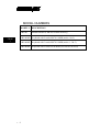
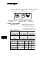
MODEL NUMBERS
CHAP.
1
MODEL #
DESCRIPTION
KB3100
Standard model (8 KB non-volatile memory)
KB3100M2 Keyboard with 2 tracks ISO7811 MSR (tracks 1 & 2)
KB3100M3 Keyboard with 3 tracks ISO7811 MSR (tracks 1, 2 & 3)
KB3100MJ
1-2
Keyboard with 2 tracks JIS II MSR (JIS I track 2 & JIS II)
TM
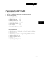
PACKAGE CONTENTS
•
•
•
Programmable keyboard
Key clip x 1 (mounted at bottom of the programmable keyboard)
Accessory bag including:
⇒ Cable CCBLA-055-2
x1
⇒ Legend sheet
x4
⇒ Quad key w/key cap
x1
⇒ Double key w/key cap
x2
⇒ Control keys 4 pcs/set
x 1 (set)
⇒ Utility software diskette x 1
⇒ User’s manual
x1
⇒ Key cap (for single key) x 104
CHAP.
2
OPTION LIST
•
•
•
•
•
•
•
MSR (ISO track 1 & 2, ISO track 1, 2 &3, or JIS I track 2 + JIS II) /pc
Soft dust cover / pc
Numerical keys (., 00, 0 to 9) /set (preprinting durability warranted)
Quad key with key cap / set
Double key with key cap / set
Blank key / pc
Single key top and key cap / set
2-1
TM
CHAP.
2
2-2
TM
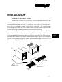
INSTALLATION
CABLE CONNECTION
Take the cable CCBLA-055-2 out of the accessory bag and connect the 6 pin
DIN male plug of the cable to the central 6 pin female connector at the bottom of the
programmable keyboard (ref. Fig. 3-1), connect the other end (5 pin DIN male plug)
to the PC or a compatible system. Connect the PC keyboard or any other keyboard
wedged input device such as a CCD scanner to the 5 pin DIN female connector at the
bottom of the programmable keyboard if such connection is required.
For installation in a PS2 or a compatible system, connect the 6 pin DIN male
plug of cable CCBLA-055-2 to the central 6 pin DIN female connector at the bottom
of the programmable keyboard as the way for PC. Connect the 5 pin DIN male plug
through a DIN 5 female - mini DIN 6 male transform plug to the PS2 or a compatible
system. Connect the PS2 keyboard or other PS2 keyboard wedged device like a CCD
scanner to the 6 pin mini DIN female connector at the bottom of the programmable
keyboard.
Monitor
PC
PC KB
P OW E
M ARSGETNAREDIP
TE
LP
L4
LO
L 3L 2L 1
R
ICER
CCBLA-055-2
KB-3100
Fig. 3 - 1
3-1
CHAP.
3
TM
KEYTOP LAYOUT
CHAP.
3
The basic layout of this programmable keyboard is a matrix with 8 rows and
14 columns to provide maximum 112 keys with the 6 position control key. However,
there are means for the user to break the monotony and to improve the efficiency in
application of this programmable keyboard.
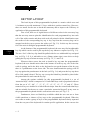
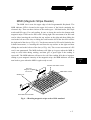
First of all, there are 4 legend sheets of different colors in the accessory bag
that the user may want to print the identification for each programmed key into each
cell of the sticker matrix and then stick each cell printed with the identification onto
the surface of the corresponding key top. A key cap from the accessory bag can be
snapped on the key top to protect the sticker (ref. Fig. 3-2). In this way the user may
feel a lot easier in using the programmable keyboard.
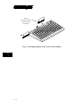
At the bottom of the programmable keyboard, the user may find an adjustable
key clip which can be used to pick up the key cap whenever required (ref. Fig. 3-2).
The two “feet” of the key clip should be pulled wide for use with double key and quad
key (ref. Fig. 3-5). It is advisable to use a flattop (minus sign) screw driver to help
getting the key top off when necessary (ref. Fig. 3-2, 3-3 and 3-4).
Whenever there comes the need to install a key top onto the programmable
keyboard, the user should notice that at the bottom of each key top, one of the four
walls is springy and in the hole on the keyboard to accept the bottom of the key top
there is a protuberance at the lower side. The user should match the springy wall of
key top against the protuberance in the hole (ref. Fig. 3-6) and press the key top down
till a click sound is heard. The key cap (except the blank key) should be placed after
the printed label is stuck onto the key top.
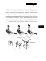
Among the options available for this programmable keyboard is a set of
“numerical keys” which is composed of 12 individual keys each is preprinted with one
from the set of “0”, “00”, “.”, “1”, “2”, “3”, “4”, “5”, “6”, “7”, “8” and “9”. These
numerical keys are molded in a little different shape from the normal individual keys
and are suitable for the user to create a particular “numerical keypad” at any zone on
the programmable keyboard which is convenient to the user (ref. Fig. 3-7).
Furthermore, there are blank keys available which the user can use to form
visible partitions or clusters of key tops on the programmable keyboard. When the
user wants to make a group of keys on the programmable keyboard clearly separated
from the rest part of the keyboard for certain specific application, he/she can use the
3-2
TM
blank keys to replace the normal individual keys around the area. The top surface of a
blank key is at the ground level of the key stroke for other keys (ref. Fig. 3-7). The
blank key will not be pressed down when pressed. The user may order for accessional
quantity of the blank keys as option for his/her application.
There are also double key and quad key available for the user to configure the
programmable keyboard such that the most frequently used keys may occupy larger
areas. The double key occupies two “vertically” adjacent positions and uses only the
bottom position for key content (ref. Fig. 3-3). The quad key occupies a two by two
matrical area and uses only the lower right position for key content (ref. Fig. 3-4).
An example of using the above mentioned alternate key tops is shown in Fig.
3-7.
CHAP.
3
Fig. 3 - 2
Fig. 3 - 3
Fig. 3 - 4
protuberance
Springy wall
Fig. 3 - 5
Fig. 3 - 6
3-3
TM
Double
key
LP
Blank keys
L4
POWER
L3 L2 L1
LO
Quad
key
MAGNETI
C
STRI
PE
READER
Numerical
keys
CHAP.
3
Fig. 3 - 7
3-4
TM
APPLICATION
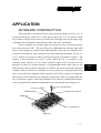
KEYBOARD CONSTRUCTION
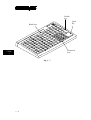
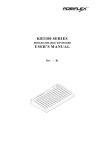
This keyboard is constructed of three parts on the top surface (ref. Fig. 4-1). A
6 position turning key switch area is at the upper right corner, a 14 x 8 matrix of push
key switches occupies most of the top surface and a left-right slot near the upper edge
is designed for the Magnetic Stripe Reader of the -M2, -M3, -MJ models.
In the rectangular area at upper right corner there are one 6 position electronic
key switch and two LED’s. The left LED is for MSR indication and the right LED
between the turning key switch and the MSR indicator is the power-on indicator. The
6 position electronic key can be turned to one of the following 6 positions: LP, L0, L1,
L2, L3 and L4. It can only be taken out from the switch at positions L0 and L1. The
purpose of this electronic key serves 3 folds: When the key is switched to (and
extracted from) position L0, the whole keyboard output will be blocked off by
hardware to work as a security measure. A programmable answer back code for the
final position of the 6 position electronic key will be sent by the keyboard to the host
computer whenever the key is switched to a new position for a programmable delay
time or when the host computer sends a specific code (E7h) to inquire the keyboard.
The position of the electronic key determines which page of the key content table for
the 112 push keys applies, while the definitions of the same key within different pages
can be programmed so absolutely independent to provide instant menu change over.
6 position key
Power-on LED
6 position key switch
MSR indicator
LP
L4
LO
L3
POWER
L2 L1
MAGNETIC
STRIPE
READER
MSR slot
14 x 8 push keys
Fig. 4 - 1
4-1
CHAP.
4
TM
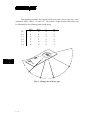
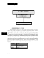
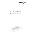
This turnable electronic key switch is delivered with a set of 4 pcs keys, each
marked as “PRG:, “REG”, “Z” and “GT”. The effective range of each of the 4 keys can
be illustrated by the following table and drawing.
LP
L0
L1
L2
L3
L4
PRG
REG
Z
GT
Y
Y
Y
Y
Y
N
N
Y
Y
Y
N
N
N
Y
Y
Y
Y
N
N
Y
Y
Y
Y
Y
LP
L4
LO
L3
L2
L1
45°
POWER
CHAP.
4
MAGNETIC
STRIPE
READER
30°
45°
30°
30°
Fig. 4 - 2 Range for each key type
4-2
TM
PRELOADED PATTERN
As the KB3100 series satisfies so many application requirements easily, it is
naturally impossible to give a definite set of key definitions to serve most of its
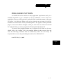
application. However, this keyboard is preloaded with a particular pattern on the page
LP before it is delivered. Please refer to the print-out on next page for the key
definition of each location of this preloaded pattern. The purpose of this preloaded
page is to serve the software designer so that you won’t have to connect an external
PC keyboard when you start to program the POS programmable keyboard.
To preserve this preloaded pattern into a computer file for later use, the user
should refer to the “readme” file on the attached diskette in the accessory box and
issue the following command from the subdirectory where the user keeps the
keyboard driver to store the preloaded pattern in the file “KB3100.TPL”:
rwm kb3100.tpl -r
CHAP.
4
4-3
TM
Print Scroll
Screen Lock
+
–
×
÷
Esc
F1
F2
F3
F4
F5
F6
Esc
F7
F8
F9
F10
F11
F12
←
↓
→
~
`
!
1
@
2
#
3
$
4
%
5
^
6
&
7
*
8
(
9
Tab
Q
W
E
R
T
Y
U
I
Cap
A
S
D
F
G
H
J
Shift
Shift
Z
X
C
V
B
Alt
Space
Space
Space
Space
Ctrl
↑
Pause
Ins
Home
PgUp
Del
End
PgDn
)
0
_
-
+
=
ï
O
P
{
[
}
]
|
\
K
L
:
;
”
’
Enter
Enter
N
M
<
,
>
.
?
/
Shift
Shift
Space
Space
Space
Space
Alt
PRINT - OUT OF PRELOADED KEY DEFINITIONS FOR PAGE LP
4-4
Ctrl
TM
MSR (Magnetic Stripe Reader)
The MSR slot is near the upper edge of the Programmable Keyboard. The
MSR indicator LED is located at the upper left corner of the block containing the
electronic key. There are three choices of the reader types – ISO dual tracks, ISO triple
tracks and JIS types. For card reading, be sure to insert the card to the bottom with
magnetic stripe of ISO card or JIS I track 2 facing right. The movement of an ISO card
can be either inserting the card from the top surface at the right end then sliding the
card to the left out of the slot, or sliding the card from the left of the slot till it reaches
the right end of the slot (ref. Fig. 4-3). Yet the movement of a JIS card is limited to the
leftward movement, i.e. inserting the card from the top surface at the right end then
sliding the card to the left out of the slot (ref. Fig. 4-4). The reverse movement of a JIS
card is not guaranteed. The MSR indicator will light up in green when the MSR is
ready to read, blink during reading, and then give a green light if the reading is
successful. The MSR indicator will turn to be red if the reading fails due to improper
sliding or poor magnetic intensity of the magnetic stripe, the MSR indicator will then
turn back to green when the MSR is again ready to read.
POWER ON INDICATOR
ISO card
Magnetic stripe
toward user
MSR INDICATOR
MSR SLOT
READER HEAD MARK
Fig. 4 - 3 Reading magnetic stripe cards of ISO standard
4-5
CHAP.
4
TM
JIS card
The side with JIS II
magnetic stripe
toward user
Fig. 4 - 4 Reading magnetic stripe cards of JIS standard
CHAP.
4
4-6
TM
PROGRAMMING THE KEYBOARD
EASINESS IN PROGRAMMING
The programmable keyboard series KB-3100 is a very powerful programmable
keyboard. It can be used under any environment that any PC or PS2 keyboard can be
applicable with its immense programmability. However the programming could seem
to be a little bit more restrictive yet very convenient. The KB-3100 series can be
programmed under Windows95, Windows 3.1, and DOS environment through
application of the utility diskette attached in the accessory. Throughout this chapter,
intention is to cover all environments possible, so the user may skip those parts not
related to the actual system of the user.
In the diskette that comes along with the KB-3100 series keyboard, there is a
program called KBM.EXE that is meant to be called upon under DOS prompt or in
the WINDOWS application after proper installation to program the programmable
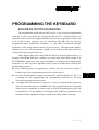
keyboard. Yet, there are three important points to bear in mind before entering this
programming program.
l As a common practice on applying any software, the user is advised to make a
backup copy of the programming utility before he/she uses it.
l It is also recommended to connect an external PC or PS2 keyboard (ref. Fig. 5-11) during the task programming this programmable keyboard for the best
convenience though not being a must.
l A straight DOS environment is required to ensure no keyboard interception to
affect the auto-detect function in KBM.EXE if the programming is to be executed
without proper installation. In other words, to perform programming to KB-3100
in the DOS box of any Windows environment, that Windows system has to be
installed with the installation utility provided in the utility diskette attached.
5-1- 1
CHAP.
5
TM
PC or PST SYSTEM
PROGRAMMABLE
KEYBOARD
EXT. KB PORT
PC or PS2 KEYBOARD
Fig. 5 - 1 - 1 Preparations
ANSWER BACK CODE
CHAP.
5
Programming the answer back codes of the 6 position electronic key-lock is
also very easy as they are included in the keyboard programming with the locations
coded as “KLP”, “KL0”, “KL1”, “KL2”, “KL3” and “KL4” in the key-layout map of
page L1. These answer back codes will be issued by the programmable keyboard to
PC whenever the 6 position electronic key is switched to a new position (there will be
a time delay as determined in the configuration of the keyboard programming utility
and is adjustable by “r” and “t” key presses, this time delay is useful to give only the
answer back code of the last position of control key when it is turned across multiple
positions) or when the keyboard receives an “enquiry” code (E7h) from the PC or the
PST system. Here are some examples of sending this “enquiry” code in different
languages:
5-1-2
Language
Syntax
C
outp (0x60, 0xE7)
BASIC
out &H60, &H0E7
DEBUG
o 60 E7
TM
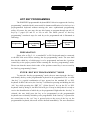
HOT KEY PROGRAMMING
The POSIFLEX programmable keyboard KB-3100 series supports the “hot key
programming” method which is most useful in instant modification of a few keys in a
preprogrammed keyboard without entering the more sophisticated programming
utility. Of course, the user may also use this feature to program through out all 112
keys by 5 pages (LP and L1 to L4) at will. The whole process of “hot key
programming” contains 4 steps for each key to be programmed and is illustrated as
following:
Preparation
Enter “hot key
programming”
mode
Input the
content to be
programmed
Exit “hot key
programming”
mode
PREPARATION
Please refer to Fig. 5-1-1, a standard PC or PS-2 keyboard must be connected
to the KB-3100 series before entering “hot key programming” mode. The user shall
then decide which key of which page is to be programmed and turn the 6 position
control key to the proper position before entering the “hot key programming” mode.
Please note that the answer back codes of the position control key is not covered by
the “hot key programming” feature.
ENTER “HOT KEY PROGRAMMING” MODE
To enter the “hot key programming” mode, the user must input the “hot key”
and identify the key on the programmable keyboard to be programmed. The so called
“hot key” is a special combination of keys pressed on the standard PC or PS-2
keyboard. In KB-3100 series, the “hot key” is defined as pressing and holding the left
“Alt” key while pressing the “PRT SC” (“Print Screen”) key on the PC or PS-2
keyboard. And by doing so, the KB-3100 will give 2 beeps to notify that it is ready to
receive the identification of which key to be programmed. Right after the “hot key” is
released, the user shall press the key to be programmed on the programmable
keyboard once to identify which key to be programmed. If the “hot key” is pressed for
the second time or the “esc” key is pressed prior to the press of the key on the
programmable keyboard, this mode will be aborted immediately. The user should not
5-1- 3
CHAP.
5
TM
enter the “hot key programming” mode when the programmable keyboard is already
fully loaded (no more free memory for further programming) by the key contents
previously programmed.
INPUT THE CONTENT TO BE PROGRAMMED
CHAP.
5
Once the programmable keyboard enters the “hot key programming” mode
with the key to be programmed identified, what the user types on the standard PC or
PS-2 keyboard will be taken for the content to be programmed into that key of the
programmable keyboard till the user exits the “hot key programming” mode.
The legal input in this mode includes all alphabetical letters (including both
upper and lower cases), numerical digits (applicable only for keys at the area above
the alphabetical keys and excluding those on the numerical keypad), symbols (such as
`!”#$ and excluding those arithmetic signs in the numerical keypad) and the “enter”
key. The “shift” key, the “caps lock” key and the “back space” key are also accepted in
this mode to serve an editing purpose (for example, pressing “back space” will erase
the last character of the input instead of being treated as a character for input).
Pressing the “esc” key in this mode will abort the “hot key programming” mode
immediately. All the rest keys (such as the “Ctrl”, “Alt”, “Home”, any function key or
arrow key or any key in the numerical keypad) on the standard PC or PS-2 keyboard
are illegal inputs in this mode. The maximum number of key presses acceptable to any
key by “hot key programming” is 32.
All the input from the standard PC or PS-2 keyboard in this mode will also be
sent to the host computer.
EXIT “HOT KEY PROGRAMMING” MODE
After the intended content of the key is completely entered, the user shall press
the “hot key” again to notify the end of “hot key programming”. The programmable
keyboard will give one beep to signify the normal exit of the “hot key programming”
mode. Should there be any illegal entry in the content of the key or any other improper
operation during the programming, the programmable keyboard will give three beeps
to signify the failure of “hot key programming” and the key content is not changed. If
the user pressed the “esc” key to abort “hot key programming”, the programmable
keyboard will also give three beeps immediately as a response to signify the abort.
5-1-4
TM
UTILITY INSTALLATION
In the utility diskette, there is a file named “INSTALL.EXE” for installation of
all the utilities into any operating system among Windows95, Windows 3.1 and DOS.
In order to give the user of all levels a clear picture of what to do during installation,
the installation procedures are illustrated step by step graphically below. Whenever
“click” is mentioned in the text, it means that the user uses a mouse. If the user does
not use a mouse in the installation procedure, the keyboard application can perform
the same effect if the user follows the instruction applicable in Windows environment.
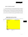
WINDOWS95 INSTALLATION
Insert the programmable keyboard utility diskette in drive A: and click the
“Start” button as indicated in Fig. 5-2-1.
CHAP.
5
Fig. 5 - 2 – 1
5-2-
1
TM
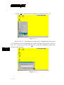
Click the “Run” command in the start menu, as indicated in Fig. 5-2-2.
Fig. 5 - 2 - 2
CHAP.
5
Refer to Fig. 5-2-3, the dialogue box of the “Run” command, the user may type
in “A:install.exe” in the command line for “Open” and click “OK” just the way like in
Fig. 5-2-7, or the user may also click “Browse” to find the installation program with
the help of the computer.
Fig. 5 - 2 - 3
5-2-2
TM
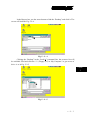
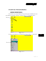
In the Browse box, use the arrow button to find the “Desktop” and click it. The
screen will look like Fig. 5-2-4.
Fig. 5 - 2 - 4
Clicking the “Desktop” in the “Look in” command line, the resource list will
be unfolded. Find and click the “3 ½ Floppy (A:)” in “My Computer” to get access of
drive A: as in Fig. 5-2-5
CHAP.
5
Fig. 5 - 2 - 5
5-2-
3
TM
Double click the file “Install.exe” or click the file only once and click the
“Open” button, as in Fig. 5-2-6.
Fig. 5 - 2 - 6
The dialogue box of the “Run” command reappears with the proper file name
in the “Open” command line. Now click “OK” to start installation.
CHAP.
5
Fig. 5 - 2 - 7
5-2-4
TM
A screen like Fig. 5-2-8 will appear, press the “y” key to continue installation.
Fig. 5 - 2 - 8
Another question will show up to ask you if you want to install the utility for
the Windows 3.1 or Windows95 as in Fig. 5-2-9. The utility will detect automatically
which Windows is being used and install itself in a correct way. Now, let us press the
“y” key to install the utility for the Windows environment.
Fig. 5 - 2 - 9
5-2-
5
CHAP.
5
TM
On the screen, there will be an input area to enter the path to the directory
where the current Windows system files are. The default value for this input is shown
on the screen like Fig. 5-2-10.
CHAP.
5
Fig. 5 - 2 - 10
However, this path can be edited to the actual situation of the user’s system by
using the left / right arrow keys, “insert”, “delete”, “home”, “end” and those keys
needed to type in the correct directory path. One example is given in Fig. 5-2-11.
Fig. 5 - 2 - 11
5-2-6
TM
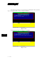
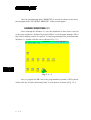
Pressing the “enter” key from either Fig. 5-2-10 or Fig. 5-2-11, a question
arises again asking if the user wants to install the utility like in Fig. 5-2-12.
Fig. 5 - 2 - 12
After the user presses the “y” key confirming the intention, the installation
starts and a message “COPYING FILES” shows up briefly as in Fig. 5-2-13 together
with some beeps denoting the installation progress from time to time.
CHAP.
5
Fig. 5 - 2 - 13
5-2-
7
TM
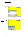
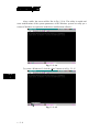
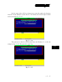
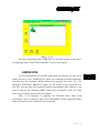
After a while, the screen will be like in Fig. 5-2-14. The utility is copied and
some modifications of the system parameters of the Windows system are ready yet a
restart of Windows is required to make these modifications effective.
Fig. 5 - 2 - 14
To restart a Windows95, click the “Start” button as in Fig. 5-2-15.
CHAP.
5
Fig. 5 - 2 - 15
5-2-8
TM
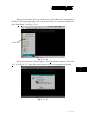
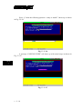
When the start menu shows up, the user may notice that a new icon named as
“Posiflex” with a keyboard shape icon is in the start menu. To restart the Windows95,
click “Shut Down” as in Fig. 5-2-16.
New icon
Fig. 5 - 2 - 16
When the shut down windows appear, click “Restart the computer?” and click
“Yes” as in Fig. 5-2-17. After this restart, the user is free to program this keyboard.
CHAP.
5
Fig. 5 - 2 - 17
5-2-
9
TM
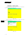
WINDOWS 3.1 INSTALLATION
Insert the programmable keyboard utility diskette in drive A: and double click
the icon for “Main” group as shown in Fig. 5-2-18.
Fig. 5 - 2 - 18
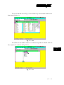
When the components of Main group show up, double click the “File
Manager” as shown in Fig. 5-2-19.
CHAP.
5
Fig. 5 - 2 - 19
5 - 2 - 10
TM
The screen like the one in Fig. 5-2-20 will show up. Now double click the box
that stands for drive A:
Fig. 5 - 2 - 20
The utilities in the diskette in drive A: will show up and now double click the
file “install.exe” as shown in Fig. 5-2-21
CHAP.
5
Fig. 5 - 2 - 21
5-2-
11
TM
The following procedures are just like those for Windows95. The screen like
Fig. 5-2-22 appears. Press “y” key to continue installation.
Fig. 5 - 2 - 22
To the question in Fig. 5-2-23, press “y” to continue.
CHAP.
5
Fig. 5 - 2 - 23
5 - 2 - 12
TM
On the screen, there will be an input area to enter the path to the directory
where the current Windows system files are. The default value for this input is shown
on the screen like Fig. 5-2-24.
Fig. 5 - 2 - 24
This path can be edited to the directory where the Windows 3.1 is, like the
example in Fig. 5-2-25. Then press the “enter” key.
CHAP.
5
Fig. 5 - 2 - 25
5-2-
13
TM
Press “y” when the following question: “ready to install?” shows up as shown
in Fig. 5-2-26.
Fig. 5 - 2 - 26
A message “COPYING FILES” will show up with some beeps as shown in
Fig. 5-2-27.
CHAP.
5
Fig. 5 - 2 - 27
5 - 2 - 14
TM
After the copying is completed, the installation procedures are done. Yet, the
Windows must be restarted to make the newly installed utility work.
DOS INSTALLATION
Insert the programmable keyboard utility diskette in drive A: and type under
A:\> prompt the following command:
A:\> install
(enter)
The screen will change to Fig. 5-2-28:
CHAP.
5
Fig. 5 - 2 - 28
Answer “y” to the above question, the screen will become to Fig. 5-2-29:
5-2-
15
TM
Fig. 5 - 2 - 29
Answer “n” to the above question. All the necessary files will be copied to the
directory “POSIFLEX.D”, and the installation is completed.
CHAP.
5
5 - 2 - 16
TM
STARTING PROGRAMMING
UNDER WINDOWS95
In the initial screen when Windows95 starts after proper installation, the user
may find an icon named as “Posiflex” as shown in Fig. 5-3-1 and double click it.
New icon
Fig. 5 - 3 - 1
Or, the user may find the icon in start menu as shown in Fig. 5-3-2 and click it.
New icon
Fig. 5 - 3 - 2
5-3- 1
CHAP.
5
TM
Once the programming utility (KBM.EXE) is activated as shown in the above,
the paragraph under “STARTING KBM.EXE” in this section applies.
UNDER WINDOWS 3.1
After restarting the Windows 3.1 once the installation is done, there is an icon
of the group marked as “Posiflex Keyboard Utilities” in the Program Manager. Move
this icon to suitable position if required. To start programming of the keyboard under
Windows 3.1, double click this icon as shown in Fig. 5-3-3.
CHAP.
5
Fig. 5 - 3 - 3
Now, to program the KB-3100 or the programmable keyboard of PST systems,
double click the “Posiflex Keyboard Utility” icon in the box as shown in Fig. 5-3-4.
5-3-2
TM
Fig. 5 - 3 - 4
Once the programming utility (KBM.EXE) is activated as shown in the above,
the paragraph under “STARTING KBM.EXE” in this section applies.
UNDER DOS
To start programming the keyboard under DOS environment, the user has to
change directory to the “POSIFLEX.D” which was established through installation,
and then type the command “KBM” followed by pressing the “enter” key. The
paragraph “STARTING KBM.EXE” applies for the actions to take afterwards. The
user may also just insert the attached keyboard programming utility diskette in the
drive A: and type the command “KBM” followed by pressing the “enter” key if the
utility was not installed under DOS environment.
There is an advantage in applying the keyboard utility under DOS
environment. There is a shortcut utility called “RWM.EXE” which is applicable under
DOS environment and is explained in next paragraph.
5-3- 3
CHAP.
5
TM
SHORTCUT UTILITY (RWM.EXE)
The feature of this RWM.EXE is designed mainly for the off-line
programming purpose and is very useful in quick reproduction of the preprogrammed
contents of the programmable keyboard. In such application, the user should have
either the preprogrammed keyboard or the preprogrammed file with “.tpl” extension
name which is the result of the keyboard programming. The user may use RWM.EXE
to directly transfer the programmed result of the programmable keyboard to a “.tpl”
file or directly transfer a prestored “.tpl” file to a programmable keyboard without
entering the utility “KBM.EXE” which may take more keystrokes. For instance, the
user wants to transfer a file “XXX.tpl”, which was saved before, to the programmable
keyboard, he/she should type in following command in subdirectory
OSIFLEX.D”:
RWM XXX.tpl
CHAP.
5
(enter)
This operation is quite recommended to be performed on a daily basis to
ensure the system stability.
On the other hand, when the user wants to save the contents of a programmed
keyboard, e.g. when he/she newly receives a programmable keyboard, to a file named
“YYY.tpl”, he/she should type in following command in subdirectory
OSIFLEX.D”:
RWM -r YYY.tpl
5-3-4
(enter)
TM
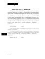
STARTING KBM.EXE
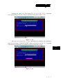
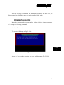
In case that the program KBM.EXE is executed for off-line programming, that
is executing KBM.EXE on a normal PC compatible machine without the
programmable keyboard attached, the program will ask a question on the display as
the following:
Fig. 5 - 3 - 5
The user should select 4 for a KB-3100 series or standard PST programmable
keyboard. If any key other than number 1 to 4 is pressed, the program will be
terminated automatically. The alternatives 1, 2 and 3 are designed for KB-2010 and
KB-2100 series programmable keyboards and early basic type of PST products
respectively and are not applicable in the KB-3100 series.
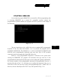
However, if the programmable keyboard is connected to the system when
entering the KBM.EXE, the program will auto-detect the type and size of the
programmable keyboard and skip this menu to start reading after getting confirmation,
the current contents of the programmable keyboard for programming. However, a
question like that in Fig. 5-3-6 will show up to confirm the intention of the user, as
from time to time, the user may want to start programming from a “blank” base. In
that case, the user should press the “ESC” key to the question in Fig. 5-3-6.
5-3- 5
CHAP.
5
TM
Fig. 5 - 3 - 6
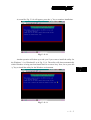
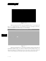
If the user presses the “ESC” key to the question in Fig. 5-3-6, the process of
Fig. 5-3-7 is skipped and Fig. 5-3-8 will show up. However, pressing any other key,
the user will find the screen like in Fig. 5-3-7 for a moment
Posiflex Programmable Keyboard Utility
vx.xx.xx
CHAP.
5
reading data from the keyboard . . .
Fig. 5 - 3 - 7
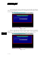
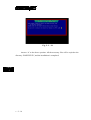
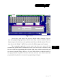
Then the screen like Fig. 5-3-8 will show up with the contents of the 8 keys of
the leftmost column of page “L1” in the key content area (in the example in Fig. 5-3-8,
these 8 keys happen to be blank). By the way, if the cursor is moved to the column of
“KLP”, the key-contents area will show only 6 entries for the answer back codes.
5-3-6
TM
Cursor
position
Program ID
Editing area
Key-layout map
Key-contents area
Positon
control
keys
Command list
Status bar
Fig. 5 - 3 - 8
In the above, each area of the screen is labeled with its function. The user
may start programming right away with the arrow keys to move around in the key
layout map to select the key or the position control key to edit the content. The user
may also use the “PgUp” / “PgDn” key to select for different page (total 5 pages).
The commands applicable in the mode that the user enters will be
automatically updated at the command list on the screen to work as a reminder so that
the user could start programming the keyboard right away with the on-line help and
the onward command listings. However, the user shall purchase a technical manual of
this programmable keyboard if he/she still want to learn more detail about this
programmable keyboard or to master the programming techniques.
5-3- 7
CHAP.
5
TM
COMMAND LISTING IN VIEW MODE
CHAP.
5
ESC -- quit the keyboard programming program
F1 -- get help on command list
F3 -- enter the configuration screen
F5 -- enter ASCII-code editing mode
F8 -- enter scan-code editing mode
F10 -- quit the keyboard programming program
Ins -- toggle insert/overwrite status for editing (default = insert)
Del -- delete the content of the key where cursor stays
Home -- go to column A of same page same row
End -- go to column I of same page same row
PgUp -- go to one page less in cyclic manner
PgDn -- go to one page next in cyclic manner
Up arrow -- move cursor to one row up in cyclic manner
Down arrow -- move cursor to one row down in cyclic manner
Left arrow -- move cursor to one column left in cyclic manner
Right arrow -- move cursor to one column right in cyclic manner
ENTER -- enter ASCII-code editing mode, but if the last edit of the key was in scancode mode then this means enter scan-code editing mode.
Alt-A -- enter ASCII-code editing mode
Alt-C -- copy the key content of a key or contents of the keys in a page to buffer
Alt-E – erase the current page or all pages
Alt-G -- enter the configuration page
Alt-L -- load key definitions from a disk file
Alt-M -- enter multi-level shift marker
Alt-N -- enter scan-code editing mode
Alt-O -- load key definitions from a disk file
Alt-P -- paste the buffer content to key definition
Alt-R -- read key definitions from the programmable keyboard
Alt-S -- save key definitions to a disk file
Alt-T – toggle key-content format between page-wise and column-wise
Alt-U -- recover key definition before last change
5-3-8
TM
Alt-W -- write key definitions to the programmable keyboard
Alt-X -- quit the keyboard programming program
any other key stoke -- will be taken as an input in ASCII-code editing mode, and will
give no influence if the current key was last edited in scan-code editing mode
COMMAND LISTING IN ASCII-CODE EDITING MODE
ESC -- enter view mode
F1 -- get help on command list of ASCII- code editing mode
F5 -- enter view mode
F8 -- enter view mode
F10 -- enter view mode
BkSp -- delete the character to the left of cursor
Ins -- toggle insert/overwrite status for editing (default = insert)
Del -- delete the character where cursor stays or the last character
Home -- go to first position within the key definition
End -- go to last position within the key definition
PgUp -- go to one page less in cyclic manner
PgDn -- go to one page next in cyclic manner
Up arrow -- move cursor to one row up in cyclic manner and enter view mode
Down arrow -- move cursor to one row down in cyclic manner and enter view mode
Left arrow -- move cursor to one character left within the key definition
Right arrow -- move cursor to one character right within the key definition
Alt-A -- enter view mode
Alt-C -- enter a “Caps Lock” into the key-content
Alt-D -- enter time delay mark into the key-content
Alt-N -- enter view mode
Alt-S -- enter a multi-level separator between definitions of different levels.
Alt-X -- enter view mode
Alt-27 -- enter an “ESC” into the key-content
Alt-8 -- enter a “BkSp” into the key-content
Ctl-C -- immediately terminates the programming utility.
any other key stoke -- will be taken as an input in ASCII-code editing mode.
5-3- 9
CHAP.
5
TM
COMMAND LISTING IN SCAN-CODE EDITING MODE
CHAP.
5
ESC -- leading code to enter scan code of any key after it into key-content, except
“ESC” + “F” for utility version since 2.15.xx
ESC-F -- leading code of arbitrary release code for utility version since 2.15.xx.
usually used to release “CTL”, “ALT” or “SHF”.
F1 -- get help on command list of ASCII- code editing mode
F5 -- enter view mode
F8 -- enter view mode
F10 -- enter view mode
BkSp -- delete the character to the left of cursor
Ins -- toggle insert/overwrite status for editing (default = insert)
Del -- delete the character where cursor stays or the last character
Home -- go to first position within the key definition
End -- go to last position within the key definition
PgUp -- go to one page less in cyclic manner
PgDn -- go to one page next in cyclic manner
Up arrow -- move cursor to one row up in cyclic manner and enter view mode
Down arrow -- move cursor to one row down in cyclic manner and enter view mode
Left arrow -- move cursor to one character left within the key definition
Right arrow -- move cursor to one character right within the key definition
Alt-A -- enter view mode
Alt-D -- enter time delay mark into the key-content
Alt-M -- enter a multi-level shift marker into the key-content
Alt-N -- enter view mode
Alt-S -- enter a multi-level separator between definitions of different levels.
Alt-X -- enter view mode
Alt-27 -- work like “ESC” as the leading code for scan codes.
Alt-8 -- enter a “BkSp” into the key-content
Ctl-C -- immediately terminates the programming utility.
any other displayable key stoke -- will be taken as an input in scan-code format.
any other non-displayable key stroke -- will have no influence
5 - 3 - 10
TM
SPECIFICATIONS
CONSTRUCTION:
CASE MATERIALS:
POWER ON LED:
KEY SWITCH TYPE:
KEY STROKE TRAVEL:
KEY TOP SIZE:
PREPRINTED KEYS:
KEY CAP:
PROGRAMMABILITY:
• METHOD:
•
•
•
•
•
•
•
•
•
•
Spill-proof, 112 keys + 6 position control key
ABS 94V0
Green
membrane plus rubber dome
3.2 mm
18 x 22 mm for normal keys (ivory)
“.”, “00”, “0 to “9”
18 x 22 mm transparent
Software under DOS, Windows 3.1, or
Windows95 without TSR program
112 keys in 5 pages by 6 position control key
ASCII or scan codes
English or European, software configured
COVERAGE:
CODE TYPE:
LANGUAGE:
KEY-CONTENTS
LENGTH:
1 - 255 byte(s)/key
MEMORY:
Non-volatile memory, 8KB
INTERCHARACTOR
OUTPUT SPEED:
programmable 0 - 140 msec
COMMANDED TIME DELAY:
programmable 0 - 240 sec
MULTILEVEL:
8 levels max.
DOWN LOAD SPEED: ≤ 40 sec. For 8 KB
CONTROL KEY:
6 positions with programmable answer back
code for each position
POSITION CONTROL KEY:
• 6 positions (LP, L0, L1, L2, L3, L4), key extractable at L0 and L1
• Hardware lock off all keyboard input after return signal sent at L0
• Capable of giving programmable answer back code of each position on
position change of the key
• Capable of giving programmable answer back code of each position on
receiving a specific code (E7h) from host computer
OUTPUT INTERFACE:
• 6 pin DIN female connector: connect to host computer
6-1
CHAP.
6
TM
• 5 pin DIN female connector: connect to input PC keyboard or Daisy Chain
device
• 6 pin mini DIN female connector: connect to input PS2 keyboard
Connects to PC through
CCBLA-055-2
Connects to PC keyboard
or Daisy Chain device
Connects to
PS2 keyboard
MAGNETIC STRIPE READER:
• Decoder & interface............. Built in keyboard wedge interface
• Tracks.................................. 1 & 2 (KB3100/1M2 for ISO7811) or
1, 2 & 3 (KB3100/1M3 for ISO7811) or
2 & rear (KB3100/1MJ for JIS X 6302)
• Start/end sentinels.................. Can be disabled by hardware jumper
Reader specification
CHAP.
6
Applicable card type
ISO 7811
JIS X 6302
Card feed method
Manual
Manual
Card feed direction
Bi-direction
Uni-direction
Read / write function
Read only
Read only
Card feed speed
5 to 55 inches/sec.
100 ~ 1200 mm/sec.
Less than 0.5%
Less than 0.1%
Error rate
Card data format
Card standard
Track used
Recording method
IATA
ABA
THRIFT
JIS I
Track 1 Track 2 Track 3 Track 2 Rear side
F2F
(FM)
F2F
(FM)
F2F
(FM)
F2F
(FM)
Recording density 210 BPI 75 BPI 210 BPI 75 BPI
Recording capacity
characters / bits
6-2
JIS II
79 / 7
40 / 5
107 / 5
40 / 5
F2F
(FM)
210 BPI
72 / 7
TM
POWER CONSUMPTION:
Voltage...................... 5VDC±10%
Current...................... 25 mA max. (Model KB3100)
50 mA max. (Models KB3100M2, KB3100M3,
KB3100MJ)
MECHANICAL:
Dimension in mm.......346 mm x 210 mm x 57 mm
Dimension in inches...13.6”x 8.3”x 2.2”
(W x D x H)
ENVIRONMENTAL:
Operating temperature......
Storage temperature.........
Relative humidity.............
Vibration..........................
Shock...............................
0°C to + 50°C
-20°C to + 70°C
90%, non-condensing
4G
40G
RELIABILITY INFORMATION:
• Push key switch:........
• Memory:....................
• MSR head life: ..........
15,000,000 strokes min.
100 years min.
300,000 passes min.
APPLICABLE CONFORMITY:
CE, FCC CLASS A
CHAP.
6
6-3
TM
CHAP.
6
6-4
TM
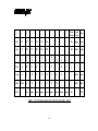
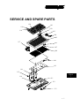
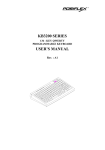
SERVICE AND SPARE PARTS
120
101
119
102
118
103
LP
L4
LO
R
POWE
L3
L2
L1
ETICPE
MAGNSTRI ER
READ
104
105
117
106
107
108
109
110
116
115
CHAP.
7
114
111
112
113
7-1
TM
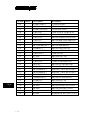
Location Choice
CHAP.
7
Part Number
Description
101
1
PSTKB112EKEY
6 POSITION KEY
102
1
MKB310LOG
KB3100 LOGO
103
1
PSTKB112ELCK6P
6 POSITION LOCK
104
1
CCBLA-207
CABLE LOCK - PKB310CPU
105
1
MKB310UHOUSG
KB3100 TOP HOUSING
106
1
CCBLA-218
KB3100 POWER LED (G)-CPU
107
1
CCBLA-217
KB3100 MSR LED (G&R)-CPU
108
1
PSTRUBRDOM
KB3100 RUBBER DOME (56)
109
1
KB112MEMBRAN-1
KB3100 MEMBRANE
110
1
PSTKBPLT-1
KB3100 STEEL PLATE
111
1
MKB310BCOVR
KB3100 BOTTOM HOUSING
112
1
CCBLA-055-2
CABLE TO PC
113
1
QC-2000
KB3100 KEY CLIP
114
1
BKB341
KB3100 I/O BOARD
115
1
CCBLA-214
CABLE I/O BOARD-CPU
116
1
KB31CPU
KB3100 CPU BOARD (2K)
116
2
KB31CPU8K
KB3100 CPU BOARD (8K)
117
1
KB3100MSRKIT-2
MSR ISO 2 TRACKS (w/cable)
117
2
KB3100MSRKIT-3
MSR ISO 3 TRACKS (w/cable)
117
3
KB3100MSRKIT-4
MSR JIS I/II (w/cable)
118
1
CLABPSTKB112
KB3100 LEGEND SHEET
119
1
PSTKBCAP
KB3100 KEY CAP
120
1
PSTKBTOP
KB3100 KEY TOP
120
2
DK-2000
KB3100 DOUBLE KEY ASSY
120
3
QK-2000
KB3100 QUAD KEY ASSY
120
4
BK-2000
KB3100 BLANK KEY
120
5
TK-2000
NUMERICAL KEY SET (12 pcs)
7-2
TM
CHAP.
7
7-3
TM
CHAP.
1
OVERVIEW
CHAP.
2
PACKAGE CONTENTS
CHAP.
3
INSTALLATION
CHAP.
4
APPLICATION
CHAP.
5
PROGRAMMING THE KEYBOARD
CHAP.
6
SPECIFICATIONS
CHAP.
7
SERVICE AND SPARE PARTS