1
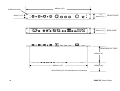
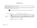
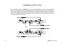
ALLEN&HEATH
User Guide
For standard version VF-1 and RIAA version VF-1R
Publication AP5917
XONE VF-1 User Guide AP5917 Issue 2
Copyright © 2004 Allen & Heath Limited. All rights reserved
Whilst we believe the information in this guide to be reliable we do not assume responsibility for inaccuracies.
We also reserve the right to make changes in the interest of further product development.
This product complies with the European Electromagnetic Compatibility directives
89/336/EEC & 92/31/EEC and the European Low Voltage Directives 73/23/EEC &
93/68/EEC.
This product has been tested to EN55103 Parts 1 & 2 1996 for use in Environments E1, E2, E3, and E4 to
demonstrate compliance with the protection requirements in the European EMC directive 89/336/EEC. During
some tests the specified performance figures of the product were affected. This is considered permissible and
the product has been passed as acceptable for its intended use.
Allen & Heath has a strict policy of ensuring all products are tested to the latest safety and EMC standards.
Customers requiring more information about EMC and safety issues can contact Allen & Heath.
NOTE: Any changes or modifications to the unit not approved by Allen & Heath could void the compliance of
the unit and therefore the user’s authority to operate it.
ALLEN&HEATH
Manufactured in the United Kingdom
Allen & Heath Limited
Kernick Industrial Estate, Penryn, Cornwall, TR10 9LU, UK
http://www.allen-heath.com
2
XONE VF-1 User Guide
Important Safety Instructions – Read First
Read instructions:
Read and retain these instructions for future reference. Read the instructions on the Safety Sheet
provided separately. Adhere to all warnings printed here and on the console and its power unit.
Cover:
Operate the unit with its cover correctly fitted. Refer servicing work to competent technical personnel
only.
Mains power:
Connect the unit to a mains power supply only of the type described in this user guide and marked
on the unit. The power source must provide a good ground connection. Do not remove or tamper
with the ground connection in the power cord. Use the power cord with sealed mains plug
appropriate for your local mains supply as provided with the unit. Route the power cord so that it is
not likely to be walked on, stretched or pinched by items placed upon or against it.
Installation:
Install the unit in accordance with the instructions printed in this user guide. Do not connect the
output of power amplifiers directly to the unit. Use audio connectors and plugs only for their intended
purpose.
Ventilation:
Ensure adequate ventilation around the unit. Do not obstruct the ventilation slots or position the unit
where the air flow required for ventilation is impeded.
Moisture:
To reduce the risk of fire or electric shock do not expose the equipment to rain or moisture or use it in
damp or wet conditions. Do not place containers of liquids on it which might spill into any openings.
Environment:
Locate the unit away from direct sunlight and any equipment which produces heat such as power
supplies, amplifiers and heaters. Protect from excessive dirt, dust, heat and vibration when operating
and storing. Avoid tobacco ash, drinks spillage, and smoke, especially that associated with smoke
machines.
Handling:
To prevent damage to the controls and cosmetics avoid placing heavy objects on the unit surfaces,
scratching the surface with sharp objects, or rough handling and vibration. Protect the controls from
damage during transit. Use adequate packing if you need to ship the unit.
XONE VF-1 User Guide
3
Important Note on Mains Voltage Setting
The internal power unit has a universal mains voltage input able to operate within the range
100V to 240V.AC 50/60Hz. Ensure that your local mains voltage is within this range. Check
that you have been supplied with an IEC mains lead fitted with a moulded mains plug suitable
for your local supply.
Important Mains Plug Wiring Instructions
The unit is supplied with a moulded mains plug fitted to the AC mains power lead. Follow the
instructions below if the mains plug has to be replaced.
The wire which is coloured Green/Yellow or Green must be connected to the terminal in the
plug which is marked with the letter E or with the Earth symbol.
This appliance must be earthed.
The wire which is coloured Blue or White must be connected to the terminal in the plug which
is marked with the letter N.
The wire which is coloured Brown or Black must be connected to the terminal in the plug which
is marked with the letter L.
Ensure that these colour codes are followed carefully in the event of the plug being changed.
4
XONE VF-1 User Guide
Contents
Important Safety Instructions .....................................................3
Front and Rear Panel Drawings .................................................6
Welcome to the XONE VF-1 ......................................................7
Front Panel Controls ..................................................................8
Rear Panel Controls .................................................................12
Rear Panel Connectors ............................................................13
Audio Cables ............................................................................15
Grounding ................................................................................16
Installing the Unit......................................................................19
MIDI ..........................................................................................20
Setting the MIDI Channel Number ...........................................21
Using MIDI to Link VF-1 Units ..................................................22
Using MIDI to Connect a Sequencer or Controller ..................23
MIDI Control Codes..................................................................24
MIDI Implementation Chart ......................................................26
Technical Specification ............................................................28
System Block Diagram.............................................................29
User Notes (blank page) ..........................................................30
XONE VF-1 User Guide
5
4
5
6
3
ENV-FOLL TO OVERDRIVE
5
6
4
3
7
2
8
1
9
0
10
SLOW
VF-1
SERIAL No:
7
2
8
1
FAST
DECAY
ENVELOPE FOLLOWER
4Hz
9
0
OFF
ON
10
VALVE OVERDRIVE
50-60Hz~
10W MAX
4
8
1
9
16 WAVEFORM 0
MIDI
OUT
FUSE
IN
6
7
ANALOGUE STEREO FILTER
12dB/Octave stereo
24dB/Octave mono
with Valve Overdrive
8
2
1
10
LOCAL
OFF
5
3
9
0
10
RESONANCE
LFO DEPTH
LFO
LEFT
RIGHT
HI-PASS
BAND-PASS
IN
JACK OUTPUT
MIX+INVERT FILTER
LEFT
RIGHT
20Hz
20kHz
VCF FREQUENCY
LOW-PASS
USE LEFT I/P 24dB/OCT
L
R
LEFT
LEFT
FILTER ON
RIGHT
RIGHT
T500mA L
250V 20mm
THIS APPARATUS MUST BE EARTHED
WARNING: FOR CONTINUED PROTECTION AGAINST RISK OF FIRE REPLACE FUSE WITH SAME TYPE AND RATING
ATTENTION: REMPLACER LE FUSIBLE AVEC UN DES MEMES CARACTERISTIQUES.
6
7
2
0.2
4
6
3
8
0.8
5
MONITOR OUT
MADE IN ENGLAND BY ALLEN & HEATH Ltd
OUTPUT
BALANCED OUT
OUT
UNBALANCED
INPUT
MONO
BALANCED IN
XONE VF-1 User Guide
Welcome to the
The XONE VF-1 is a high quality 1U rack analogue filter unit
featuring an enhanced version of the legendary VCA filter circuit
used in our award winning XONE mixer range.
Three different filter types are provided, high-pass, band-pass
and low-pass. These can be selected together to create further
types, for example high-pass and low-pass together produce a
notch filter. The filter frequency can be swept either manually or
automatically in several different ways to create stunning or subtle
performance effects.
A resonance control adjusts the sharpness of the filter from a
gentle roll off to a peaky maximum reminiscent of the distinctive
sound of the classic analogue synthesiser. The ARC (automatic
resonance control) monitors the output of the filter to
automatically reduce the resonant peaks of high level signals so
avoiding potentially system damaging transients. For further
protection all the filter controls are “soft switched” to prevent
clicks during performance.
progressively increased to create musically pleasing second
harmonic distortion. This is a great tool for adding warmth to a
mix or for fattening up thin bass sounds. Automatic gain
reduction circuitry maintains a near constant output level as the
overdrive control is increased.
An envelope follower with switchable release time allows the filter
cut-off frequency to be modulated by the intensity of the input
signal. This can be used to create some interesting effects,
particularly with drum loops and bass lines, or be switched into
the valve circuit to give intensity modulated overdrive.
A wide range LFO (low frequency oscillator) with square/triangle
waveforms completes the modulation toolbox for the filter system.
The VF-1 can send and receive MIDI allowing the filter frequency,
type and on/off status to be remotely controlled or saved to a
sequencer. It can be configured to operate in several different
modes to interface to our MIDI equipped Xone:92 DJ mixer, a
sequencer, or to track the filters to MIDI notes.
Using a rear panel switch the filter can be configured as 2-pole
stereo 12dB/octave or 4-pole mono 24dB/octave without the need
to re-patch. Another rear panel switch can sum the inverted filter
signal with the non filtered input to create cancellation effects
providing some unusual and subtle sounds, especially when
routed to an external effects unit such as reverb or delay.
The VF-1 is equipped with a wide range of input and output
connectors including balanced XLR, TRS jack and RCA phono
with optional RIAA preamp, making it easy to connect to almost
any system. A dedicated monitor output is provided to allow the
filtered sound to be previewed before switching in the effect.
As well as the VCA filter the VF-1 also features a valve (tube) input
stage with drive control. The signal level though the valve can be
Whether you are a serious DJ or a professional production studio
we hope you enjoy using the uniquely powerful XONE VF-1.
Andy Rigby-Jones, the designer
XONE VF-1 User Guide
7
Front Panel Controls
5
1
4
5
6
3
ENV-FOLL TO OVERDRIVE
5
6
4
3
7
2
8
1
9
0
10
SLOW
ENVELOPE FOLLOWER
8
1
FAST
DECAY
9
0
10
1
OFF
ON
3
4
8
0.8
5
LFO
4
6
3
7
8
1
16 WAVEFORM 0
0.2
9
10
LFO DEPTH
11
12
13
6
ANALOGUE STEREO FILTER
7
12dB/Octave stereo
24dB/Octave mono
with Valve Overdrive
8
2
1
9
0
10
RESONANCE
4
Envelope Follower
Envelope Follower Decay
Sets the decay speed of the envelope follower, either slow or fast.
This changes the sound of the effect according to the type of
music played.
8
5
3
The envelope follower modulates the filter cut-off frequency in
direct proportion to the intensity of the input signal. For example,
with low-pass filter selected and set to a low 20Hz, turning up the
envelope follower will produce a dynamic effect as the filter cut-off
frequency rises and falls along with the loudness of the music.
2
9
8
2
VALVE OVERDRIVE
2
7
4Hz
7
2
6
HI-PASS
BAND-PASS
LOW-PASS
20Hz
20kHz
VCF FREQUENCY
FILTER ON
10
3
Valve Overdrive
Turn this up to increase the amount of signal passing through the
valve (tube) stage. This increases the second harmonic distortion
and valve compression effect created which produces a pleasing
‘fattening’ of the sound. At minimum the signal is low enough to
ensure that the valve is operated in its linear region with little
effect. Continuing to increase the level of overdrive will first cause
the valve to “soft clip”, ideal for music sources, and then bring in
“hard clip” circuitry making the effect much more pronounced,
better suited to changing the character of instrument sounds such
as a bass line. The control includes a ‘make-up gain’ element
which controls the ratio between input and output level so that the
volume does not seem to increase too much as the overdrive, and
therefore distortion/compression effect, is increased.
XONE VF-1 User Guide
4
Envelope follower to overdrive
Enables the envelope follower circuit to modulate the valve
overdrive so that the valve distortion/compression effect increases
dynamically with the music. Produces a subtle, interesting effect..
5
LFO Speed
Sets the speed at which the LFO (low frequency oscillator) will
modulate the filters, from a slow 0.2Hz (approximately 12BPM) to
a very fast 16Hz (960 BPM).
6
LFO Waveform
Selects the type of waveform that the LFO outputs to modulate the
filter. A triangle output will smoothly sweep the filter cut-off
frequency up and down, whilst a square wave will produce an
instant cut-off frequency change rather like a “gating” effect.
8
Resonance
The resonance control alters the way the filter behaves at its cutoff frequency. With the control at minimum the filter will have a
gentle roll-off and therefore a smooth, subtle sound. At maximum
the filter will have extra gain at its cut-off frequency, greatly
emphasising any sound at this frequency.
Care should be taken when using the filter unit with the resonance
set at maximum as it may cause clipping in the signal path.
However the VF-1 includes an automatic resonance control (ARC)
circuit that reduces the amount of resonance at high signal levels
so minimising the likelihood of distortion. Also, the ARC circuit will
automatically reduce the amount of resonance at low frequencies
where there is higher energy level and therefore greater chance of
damage to low frequency speaker drivers.
When the two VF-1 filters are combined as a single mono
24dB/oct unit the amount of resonance will be doubled.
The diagram below shows the effect around the filter cut-off
frequency of increasing the resonance.
RESONANCE
HIGH
MID
7
LFO Depth
Adjusts the level (or depth) of LFO modulation. Set anti-clockwise
for no effect, turn clockwise to increase the effect.
LOW
0dB
CUT-OFF POINT
20Hz
XONE VF-1 User Guide
FREQUENCY
20kHz
9
9
Hi-Pass
HI-PASS FILTER
+20
+15
Turn on the high-pass filter to progressively remove low
frequencies below the cut-off selected using the VCF
FREQUENCY control [12]. The switch illuminates when the hipass filter is active. The diagram shows the response as the
frequency control is rotated. It also shows the boost around the
cut-off frequency when resonance is increased.
+10
Band-Pass
Turn on the band-pass filter to progressively remove frequencies
above and below the cut-off selected using the VCF FREQUENCY
control [12]. The switch illuminates when the band-pass filter is
active. The diagram shows the response as the frequency control
is rotated. It also shows the boost around the cut-off frequency
when resonance is increased.
-5
-10
-15
Lo-Pass
Turn on the low-pass filter to progressively remove high
frequencies above the cut-off selected using the VCF
FREQUENCY control [12]. The switch illuminates when the lowpass filter is active. The diagram shows the response as the
frequency control is rotated. It also shows the boost around the
cut-off frequency when resonance is increased.
20
100
1kHz
10k
20k
BAND-PASS FILTER
+20
+15
+10
LO
+5
HI
0dB
-5
-10
-15
-20
11
HI
0dB
-20
10
LO
+5
20
+20
100
1kHz
10k
20k
LO-PASS FILTER
+15
+10
LO
+5
HI
0dB
-5
-10
-15
-20
10
20
100
1kHz
10k
20k
XONE VF-1 User Guide
12
VCF Frequency
Sets the cut-off frequency of the filter from 20Hz (fully anticlockwise) to 20kHz (fully clockwise). This lets you sweep the
frequency across the full audio range to create dramatic
performance effects.
13
Filter On
Press this switch to route the audio signal through the valve
overdrive and filter circuits. In the off mode the signal bypasses
the filter and valve stages and is routed directly from input to
output at unity gain. When selected the switch illuminates.
The filter ON switch is also ‘soft switched’ so that it can be used
during performance to switch the filter in or out without audible
clicks.
Using the Filters
The three filter select switches are ‘soft switched’ and therefore
will not produce any transient clicks when switched. This means
the filters can be seamlessly switched in and out during
performance to create the required effects.
The filters can be used as a mix aid or an effect. For example, you
can introduce a track by sweeping the Hi-pass filter anti-clockwise
from high to low to gradually add the mid and low music energy.
You can also introduce the bass beat of a track using the Lowpass filter to gradually bring in the higher frequency definition of
the music. Sweeping a resonant filter across or in time with a
track can add a unique effect to a performance. Using the filters
with a bass line or an instrument can add a new dimension to its
sound. Experiment with the Envelope Follower and LFO too.
More than one filter type may be selected at the same time.
Simply press two or more switches simultaneously. The selected
filter switches illuminate to show they are active:
Notch –
Note:
With no filter type selected the audio signal is muted
(turned off).
Combine Hi-pass and Low-pass. Used with low
settings of RESONANCE you get a phasing effect as a small
range of frequencies is removed. Try sweeping the effect across
the full audio frequency range.
All pass
– Combine Hi-pass, Band-pass and Low-pass.
A
surprising effect considering that all frequencies are ‘passed’.
However, the filter type interaction around the cut-off point creates
an interesting effect that varies from subtle to dramatic depending
on the setting of the RESONANCE control.
Try playing different types of music and experiment with the
controls. The creative possibilities of the VF-1 are limited only by
your imagination…
XONE VF-1 User Guide
11
Rear Panel Controls
1
50-60Hz~
10W MAX
VF-1
MIDI
OUT
FUSE
LOCAL
OFF
LEFT
THIS APPARATUS MUST BE EARTHED
WARNING: FOR CONTINUED PROTECTION AGAINST RISK OF FIRE REPLACE FUSE WITH SAME TYPE AND RATING
ATTENTION: REMPLACER LE FUSIBLE AVEC UN DES MEMES CARACTERISTIQUES.
MONITOR OUT
MADE IN ENGLAND BY ALLEN & HEATH Ltd
RIGHT
USE LEFT I/P 24dB/OCT
L
R
OUT
OUTPUT
BALANCED OUT
Local Off
Mix+Invert filter
Mixes the inverted (polarity reversed) filter signal and the unfiltered
input signal together and sends the difference to the TRS jack
output. Create some interesting effects by feeding this signal
through an effects unit and then mixing it back with the original in
a mixing console.
12
IN
JACK OUTPUT
MIX+INVERT FILTER
LEFT
To enable the unit to receive MIDI the local OFF switch must be
selected.
This switch also re-routes the front panel VCF
Frequency control to control the filter via the MIDI processor rather
than direct..
2
RIGHT
3
LEFT
LEFT
RIGHT
RIGHT
T500mA L
250V 20mm
SERIAL No:
1
IN
2
UNBALANCED
3
INPUT
MONO
BALANCED IN
Mono
Switches the unit from 12dB/oct stereo to 24dB/oct mono.
In the normal stereo position, two valve overdrive/filters are
provided, one for the left signal, the other for right. Each filter has
a 12dB per octave slope.
When pressed the two are combined internally in series to provide
a single mono valve overdrive/filter. This provides a much steeper
24dB per octave slope, and twice the resonance. Plug a mono
source into the LEFT input. The output is presented to both the
LEFT and RIGHT output connectors.
XONE VF-1 User Guide
Rear Panel Connectors
1
2
50-60Hz~
10W MAX
VF-1
3
MIDI
OUT
FUSE
IN
4
LOCAL
OFF
LEFT
5
RIGHT
7
RIGHT
9
IN
JACK OUTPUT
MIX+INVERT FILTER
LEFT
8
USE LEFT I/P 24dB/OCT
L
R
LEFT
LEFT
RIGHT
RIGHT
T500mA L
250V 20mm
SERIAL No:
THIS APPARATUS MUST BE EARTHED
WARNING: FOR CONTINUED PROTECTION AGAINST RISK OF FIRE REPLACE FUSE WITH SAME TYPE AND RATING
ATTENTION: REMPLACER LE FUSIBLE AVEC UN DES MEMES CARACTERISTIQUES.
MONITOR OUT
MADE IN ENGLAND BY ALLEN & HEATH Ltd
OUT
OUTPUT
BALANCED OUT
UNBALANCED
INPUT
MONO
BALANCED IN
6
1
AC Mains Input and Fuse
Plug in the IEC mains lead with moulded plug suitable for the local
mains voltage supply. The internal power supply has a universal
input which accepts a mains voltage in the range 100V to 240V AC
50/60Hz. Make sure your local voltage is within this range.
Before plugging in, read the Important Safety
Instructions printed at the start of this user guide and the
warnings printed on the VF-1 rear panel.
The VF-1 does not have a power on/off switch. Switch on the
mains supply to power the unit.
XONE VF-1 User Guide
2
MIDI Out and MIDI In
5 pin DIN sockets. Connect to MIDI compatible equipment using
standard 5 pin DIN (MIDI) leads. Press the Local OFF switch if
you are using the MIDI function.
3
Monitor Out
¼” TRS jack output. Tip = left, ring = right, sleeve = ground.
Connect to an external console or speaker monitoring system, or
plug in high impedance (>70 ohms) headphones. This lets you
preview the effect of the filter even when it is bypassed.
13
4
Left and Right XLR Outputs
Electronically balanced, wired pin 2 hot (+), pin 3 cold (-) and pin
1 ground. Nominal output level is +4dBu with a massive +22dB
headroom up to a maximum +26dBu drive. The XLR output is
designed to operate with professional balanced equipment such
as speaker processors, mixing consoles and amplifiers.
5
Left and Right TRS Jack Outputs
These alternative main outputs are impedance balanced meaning
they provide the benefit of cable interference rejection when
connected to balanced equipment inputs. They can also connect
to unbalanced equipment without the need for cable adaptors.
Nominal output level is 0dBu with +22dBu maximum. The jack
outputs provide the switched Mix+Invert function.
6
Left and Right RCA Phono Outputs
Note: You may connect to all the outputs at the same time.
Using the three different connector types you can provide a split
of the output signal to several different destinations.
Left and Right RCA Phono Inputs
VF-1 standard version: Connect stereo line level music sources
such as CD, MD, DAT, drum machines, keyboards or other
instruments. Do not connect turntables which require RIAA
equalisation. Nominal level is 0dBu.
VF-1R (RIAA) version: Only connect turntables which require
RIAA equalisation – line level sources will overload the preamp
and cause severe distortion. Refer also to page 16 (Grounding).
8
Left and Right TRS Jack Inputs
Balanced, wired tip hot, ring cold, sleeve ground. Nominal level is
0dBu. These provide an alternative input for sources such as
mixers and instruments equipped with jack sockets. They can
work with balanced or unbalanced sources. For unbalanced
sources link the jack ring connection to ground.
9
Provide a convenient connection to consumer equipment such as
domestic amplifiers, recorders and DJ mixers.
They are
unbalanced with nominal 0dBu level.
14
7
Left and Right XLR Inputs
Balanced, wired pin 2 hot, pin 3 cold, pin 1 ground. Nominal
input level is +4dBu. Use these inputs for connection to
professional balanced equipment.
Note: Connect to only one pair of inputs at any time. Do not
attempt to mix sources together by plugging into to more than
one connector type.
Note: Plug into the Left input when operating the VF-1 in mono
mode. In this mode the right input is not used.
XONE VF-1 User Guide
Audio Cables
To ensure the high quality performance for which the VF-1 has been designed, we recommend the use of
professional grade cables and connectors. Avoid the use of cheap domestic parts. Ensure all wiring is
checked for reliable connection and safety grounding. The diagram below illustrates the more common audio
cables used.
XONE VF-1 User Guide
15
Grounding
The connection to ground (earth) in an audio system is important for two reasons:
•
SAFETY - To protect the operator from high voltage electric shock, and
•
AUDIO PERFORMANCE - To minimise the effect of ground loops which result in
audible hum and buzz, and to shield the audio signals from interference pickup.
For safety it is important that all equipment grounds are connected to mains
ground so that exposed metal parts are prevented from carrying high voltage which can
injure or even kill the operator. It is recommended that the system engineer check the
continuity of the safety ground from all points in the system including microphone
bodies, turntable chassis, equipment cases, and so on.
The same ground is also used to shield audio cables from external interference such as the
hum fields associated with power transformers, lighting dimmer buzz, and computer radiation.
Problems arise when the signal sees more than one path to mains ground. A ‘ground loop’
results, causing current to flow between the different ground paths. This condition is usually
detected as a mains frequency audible hum or buzz.
When connecting a VF-1R unit (fitted with RIAA preamp option) to a turntable, be sure to
connect the turntable ground wire to the chassis ground screw on the VF-1R to prevent hum.
CHASSIS GROUND SCREW
16
XONE VF-1 User Guide
To ensure safe and trouble-free operation we recommend the following:
•
Have your mains system checked by a qualified electrician If the supply grounding is solid to start
with you are less likely to experience problems.
•
Do not remove the ground connection from the power unit mains plug The console chassis is
connected to mains ground through the power cable to ensure your safety. Audio 0V is connected to
the console chassis internally.
•
Make sure that turntables are correctly grounded Chassis ground terminals are provided on the
console rear panel to connect to turntable earth straps.
•
Deal with ground loops Should you experience hum or buzz caused by ground loops, check first
that each piece of equipment has its own separate path to ground. If so, operate ground lift switches
on connected equipment in accordance with the instruction manuals. Alternatively disconnect the
cable screen at one end, usually the destination end. This breaks the offending loop while still
maintaining the signal shielding down the length of the cable.
•
Use low impedance microphones and line level equipment rated at 200 ohms or less to reduce
susceptibility to interference. The console outputs are designed to operate at very low impedance to
minimise interference problems.
•
Use balanced connections for the microphone and main outputs as these provide further immunity
by cancelling out interference that may be picked up on long cable runs.
•
Route cables to avoid interference To avoid interference pickup keep audio cables away from
mains power units and cables, thyristor dimmer units and computer equipment. Where this cannot be
avoided, cross the cables at right angles to minimise interference.
•
Use good quality cables and connectors and check for correct wiring and reliable solder joints. Use
professional grade short cables to connect your turntables to the console RIAA inputs. Allow sufficient
cable loop to prevent damage through stretching.
XONE VF-1 User Guide
17
4x M6 rack bolts
482mm (19“)
1U
FRONT PLATE
44mm (1¾ “)
32mm (1¼“)
39mm (1½“) REAR CASE
FROM REAR OF FACE
125mm (5”)
430mm (17“)
200mm (8”)
Allow 75mm (3”) min clearance for connectors
18
XONE VF-1 User Guide
Installing the Unit
19” rack mount
The VF-1 fits into a standard 19” rack system taking up 1U height. Use M6 bolts with plastic protective
cups. These are usually supplied by the rack manufacturer.
Plinth or furniture mount
The VF-1 can be mounted in a custom built plinth or other furniture. Use the cutting
template details shown here. The dimensions allow clearance for the cover fixing screws. Secure with suitably long M6 bolts
and nuts. Use protective cups to protect the unit’s surface.
Allow adequate ventilation around the unit. Do not obstruct the top cover ventilation slots.
4x M6 bolt clearance (dia 7mm)
CUTOUT 434mm (17 3/32“) X 40mm (1 18/32“)
20mm (25/32“)
16mm (5/8“)
217mm (8 17/32“)
233mm (9 3/16“)
XONE VF-1 User Guide
19
MIDI
MIDI is short for Musical Instrument Digital Interface. It is the popular serial connection
standard conceived in the 1980’s so that keyboards and other electronic instruments could
communicate with each other. Applications now include sound and lighting consoles,
computer sequencing, show control and performance effects control. The XONE VF-1 has
MIDI In and Out sockets allowing external control of the filter and synchronization with other
MIDI devices.
The XONE VF-1 MIDI interface provides full in and out external control of the filter type, cut-off
frequency and on/off settings. The filter can integrate with MIDI equipped sequencers, effects
units, mixers and keyboards to create a new dimension to live performance and recorded
sound.
Three additional MIDI In modes can be selected to give maximum flexibility for advanced users.
These allow the unit to be controlled in a variety of ways from the controls on the Allen & Heath
XONE:92 DJ mixer or from the notes on a standard MIDI keyboard. The MIDI channel number
defaults to 16 but can be easily changed to any channel from 1 to 16.
The following filter parameters can be controlled by MIDI:
Filter cut-off frequency
Hi-pass in/out
Band-pass in/out
Low-pass in/out
Filter on/off
20
XONE VF-1 User Guide
Setting the MIDI Channel Number
The MIDI channel number and mode settings on the XONE VF-1 are adjusted using power-up menus. These
are accessed by holding down buttons while applying power to the unit. We advise that you turn the amplifiers
off and remove the VF-1 from the audio signal path while changing MIDI settings to avoid unexpected sounds
being generated.
MIDI Ch
Hi-pass
Band-pass
Low-pass
Filter ON
1. Hold down the Hi-pass filter button whilst switching on the
power to the VF-1. All three of the filter type indicators will light.
1
X
X
X
X
2. Release the Hi-pass button. The current MIDI channel number
will be displayed encoded on the front panel lights (see table).
2
X
X
X
O
3
X
X
O
X
4
X
X
O
O
5
X
O
X
X
6
X
O
X
O
7
X
O
O
X
8
X
O
O
O
9
O
X
X
X
10
O
X
X
O
11
O
X
O
X
12
O
X
O
O
13
O
O
X
X
14
O
O
X
O
15
O
O
O
X
16
O
O
O
O
3. Press the High-pass button repeatedly to cycle through MIDI
channels 1 to 16.
4. To store the selected MIDI channel and continue with normal
operation press the Filter ON button.
HI-PASS
BAND-PASS
LOW-PASS
X = light off, O = light on
XONE VF-1 User Guide
FILTER ON
21
Using MIDI to Link VF-1 Units
For more dramatic effects two XONE VF-1 units can be connected together to make a stereo 24dB/Octave
system. Connect a MIDI cable from the MIDI Out of the first VF-1 (master) to the MIDI In of the second (slave).
Press in the rear-panel Local Off switch on the slave to allow it to respond to MIDI In messages. The slave VF-1
will now follow the filter type, cut-off frequency and filter on/off settings of the master. Switch both the master
and the slave to MONO using the rear-panel switch on each. Now route one channel through the master and
the second channel through the slave.
VF-1
VF-1
22
XONE VF-1 User Guide
Using MIDI to Connect a Sequencer or Effects Controller
By connecting the XONE VF-1 to an external sequencer you can record and replay filter sweeps and settings changes.
Connect the MIDI Out from the VF-1 to the MIDI In of a sequencer and the MIDI In on the VF-1 to the MIDI Out of the
sequencer. Configure MIDI Thru on the sequencer to echo MIDI Input to MIDI output. Now make sure that the Local OFF
switch on the rear-panel is selected so that the VF-1 will respond to MIDI In messages.
16
VF-1
XONE VF-1 User Guide
23
MIDI Control Codes
The XONE VF-1 has a standard set of MIDI control assignments. This is always used for MIDI
output and input and cannot be disabled. Three additional MIDI In modes can be enabled to
allow for advanced applications using additional MIDI messages.
Standard MIDI Assignments
These are used for both MIDI Input and output. To control the
filter using MIDI make sure the VF-1 rear panel Local OFF switch
is pressed in. For all parameters, except VCF Frequency, MIDI
outputs the current status of the filter regardless of the setting of
the Local OFF switch or whether the filter was changed using the
front panel switches or MIDI input. For the VCF Frequency, MIDI
outputs the current position of the front-panel control, not the
actual filter cut-off frequency. This means that the VCF Frequency
MIDI output follows the front panel control whilst the VF-1 filter
follows the MIDI input.
24
XONE VF-1 Function
Controller
Code
Controller
Name
High-Pass Filter
CC80
GP Button 1
Band-Pass Filter
CC81
GP Button 2
Low-Pass Filter
CC82
GP Button 3
Filter On/Off
CC83
GP Button 4
VCF Frequency
CC74
Brightness
XONE VF-1 User Guide
Mode 1 : XONE:92 Controller Mode
Connect the MIDI output of an Allen & Heath XONE:92 DJ Mixer to
the MIDI input of the VF-1 and enable this option. The rear-panel
Local OFF switch should be pressed in to allow the VF-1 to
receive MIDI messages. It is also important to set the MIDI
channel of the VF-1 to the same channel used by the XONE:92.
See your XONE:92 users guide for information on its MIDI channel
assignment. With this mode enabled some of the XONE:92
controls can now be used to alter the filter settings on the VF-1.
Mode 2 : Keyboard Tracking Mode
With this mode enabled, the VCF Frequency will follow the pitch of
key presses on a MIDI keyboard connected to the VF-1 MIDI
Input. For this to work correctly the VF-1 and the keyboard must
be set to use the same MIDI Channel. With the band-pass filter
selected its centre frequency will be approximately 1 octave above
the corresponding note on the keyboard.
Mode 3 : Keyboard Mute Mode
When enabled, this mode causes a key press on an a connected
MIDI keyboard to switch the filter type to the last setting used. On
releasing all keys on the keyboard the sound will be muted (by
deselecting all filter types). By combining MODE 1 and MODE 2
the VF-1 filter will pick out only the frequencies around the note
you press on the keyboard. Try experimenting with this on music
or synthesiser sounds to get an idea of the range of effects
possible.
XONE VF-1 User Guide
XONE VF-1 Function
Controller
Code
XONE:92 Control
Filter Type Selection
CC13
VCF 2 FREQ
Filter On/Off
CC92
Crossfader
movement
VCF Frequency
CC12
VCF 1 FREQ
Selecting the MIDI In Modes
1. Hold down the Filter ON button whilst switching on the power
to the XONE VF-1. All three of the Filter Type indicators will light.
2. Release the Filter ON button. The current mode settings will be
displayed on the three Filter Type indicator lights (see table).
Press the Filter Type buttons to toggle each mode on or off.
3. To store the mode settings and return to normal operation
press the Filter ON button again.
Mode 1
XONE:92
HI-PASS
Mode 2
KB tracking
BAND-PASS
Mode 3
KB mute
LOW-PASS
25
XONE VF-1 MIDI Implementation Chart
O = Available
Function
X = Not used
Transmitted
Received
Remarks
Default
16
16
Option
1-16
1-16
Transmits and receives on
the same MIDI channel
Default
X
X
Messages
X
X
Altered
X
X
Note Number
X
O
Keyboard tracking mode
Note ON
X
O
Keyboard mute mode
Note OFF
X
O
Keys
X
X
Channel
X
X
Pitch Bend
X
X
Basic Channel
Mode
Velocity
Aftertouch
26
XONE VF-1 User Guide
Function
Transmitted
Received
74
O
O
80
O
O
81
O
O
82
O
O
83
O
O
12
X
O
13
X
O
92
X
O
Program Change
X
X
System Exclusive
X
X
Song Position
X
X
Song Select
X
X
Tune Request
X
X
Clock
X
X
Commands
X
X
Local On/Off
X
X
All Notes Off
X
X
Active Sensing
X
X
System Reset
X
X
Remarks
Control Change
XONE:92 controller mode
System Common
System Real Time
Aux Messages
XONE VF-1 User Guide
27
Technical Specification
Operating Levels
Connection Impedances
XLR
+4dBu
Headroom +22dB
Line Inputs
>9K ohms
Jack
0dBu
Headroom +22dB
Outputs
<50 ohms
RCA
0dBu
Headroom +22dB
RIAA Preamp (VF-1R version)
3-140mV
Maximum output
47K/330pF
XLR +26dBu
TRS jack +22dBu
Frequency Response
Line to Main output
Distortion
10Hz-30KHz
Type
VCF, stereo 12dB/octave or mono 24dB/octave
selectable hi-pass, band-pass, lo-pass, notch, all-pass
Sweep range
20Hz-20KHz
Control
Manual, envelope follower, LFO, MIDI
Resonance
Variable, Automatic resonance control
+0/-0.5dB (Filter OFF)
at 1KHz +4dBu out
THD + Noise <0.002% (Filter OFF)
Noise Performance
rms 22Hz-22KHz
Residual output noise measured at XLR output
28
Filter
Filter off
<-100dBu (104dB S/N)
Filter on
<-85dBu (89dB S/N)
Valve Overdrive
Type
ECC82 (12AU7)
Control
Manual, envelope follower
System
Power supply
Internal Universal Input
Power consumption 14W Max, 7W nominal
XONE VF-1 User Guide
BLOCK DIAGRAM
ENVELOPE FOLLOWER
VALVE OVERDRIVE
FREQUENCY
RESONANCE
LFO SPEED
ANALOGUE STEREO FILTER
DECAY
0
INPUTS
EF TO OD
0
10
10
WAVEFORM
0
10
FILTER ON
HI-PASS BAND-PASS LOW-PASS
OUTPUTS
MIDI OUT
DC
JACK
0dBu
MIDI AND SWITCH
PROCESSOR
ENV FOLLOWER
SIDECHAIN
MIDI IN
LFO
LEFT XLR IN
L
+4dBu
JACK
FREQUENCY
L
R
FILTER BLOCK
0dBu
RIGHT XLR IN
LEFT XLR
+
RIAA PRE-AMP
(VF-1R VERSION)
3-140mV
47K/330pF
RESONANCE
+
R
FILTER TYPE
+
PHONO IN
0dBu
L
+4dBu
LOCAL
OFF
VALVE
STAGE
0dBu
PHONO
BYPASS
R
+4dBu
+4dBu
MONO SWITCH (24dB/OCTAVE)
RIGHT XLR
0dBu
0dBu
+
MONITOR OUT
LEFT JACK
+
INPUT +
INVERSE FILTER
XONE VF-1 User Guide
0dBu
RIGHT JACK
29
User Notes:
30
XONE VF-1 User Guide
XONE VF-1 User Guide
31
32
XONE VF-1 User Guide