1
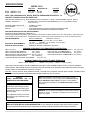
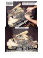
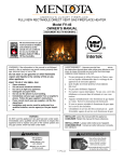
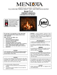
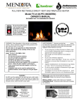
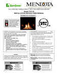
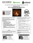
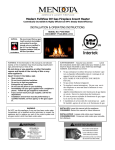
FULLVIEW RECTANGLE DIRECT VENT GAS FIREPLACE HEATER
Model FV-41-PF2
OWNER’S MANUAL
DOCUMENT NO. FV41-PF2-OM-0911
WARNING: If the information in this manual is not followed
exactly, a fire or explosion may result causing property damage, personal injury or loss of life.
Do not store or use gasoline or other flammable
vapors and liquids in the vicinity of this or any
other appliance.
WHAT TO DO IF YOU SMELL GAS
·
Open windows.
·
Do not touch electrical switches.
·
Do not try to light any appliance.
·
Extinguish any open flame.
·
Do not use the phone in your building.
·
Immediately call your gas supplier from a neighbor's
phone. Follow the gas supplier’s instructions.
·
If you cannot reach your gas supplier, call the fire
department.
·
Installation and service must be performed by a
qualified installer, service agency or the gas supplier.
WARNING
Do NOT use this appliance if any part has been under water.
Immediately call a qualified service technician to inspect the
appliance and to replace any part of the control system and
any gas control, which has been under water.
AVERTISSEMENT : Assurez-vous de bien
suivre
les instructions donné dans cette notice pour réduire au minimum le risque d’incendie ou pour éviter tout dommage
matéeriel, toute blessure ou la mort.
·
·
·
·
·
·
·
Ne pas entreposer ni utiliser d'essence ni d'autres vaperurs ou liquides inflammables dans le voisinage de cet
appareil ou de tout autre appareil.
QUE FAIRE SI VOUS SENTEZ UNE ODEUR
DE GAZ:
Ne pas tenter d'allumer d'appareil.
Ne touchez à aucun interrupteur. Ne pas vous servir des
téléphones se trouvant dans le batiment où vous vous
trouvez.
Appelez immédiatement votre fournisseur de gaz depuis
un voisin. Suivez les instructions du fournisseur.
Si vous ne pouvez rejoindre le fournisseur de gaz, appelez le service dos incendies.
L'installation et service doit être exécuté par un qualifié installer, agence de service ou le fournisseur de gaz.
INSTALLER: Leave this manual with the appliance.
CONSUMER: Retain this manual for future reference.
INSTALLATEUR : Laissez cette notice avec l’appareil.
CONSOMMATEUR : Conservez cette notice pour consultation ultérieure.
FOR YOUR SAFETY
A qualified installer, service agency, or the gas supplier must perform installation and service.
Do not store or use gasoline or other flammable vapors and liquids in the vicinity of this or any other appliance.
WARNING
Do not operate this appliance with the glass removed,
cracked or broken. A licensed or qualified person
should do replacement of glass.
AVERTISSEMENT. Ne pas utiliser l’appareil si le
panneau frontal en verre n’est pas en place, est
craqué ou brisé. Confiez le remplacement du panneau
à un technicien agréé.
WARNING
Mendota gas fireplaces are heat producing appliances. Do not burn wood, paper or other materials in this
fireplace. This fireplace is designed as a supplement
heat source. It is advisable to have an alternative primary heat supply.
In the Commonwealth of Massachusetts:
·
Installation must be performed by a licensed
plumber or gas fitter;
· A CO detector shall be installed in the room
where the appliance is installed.
WARNING: Improper installation, adjustment, alteration, service or maintenance can cause injury or property damage. Refer to this manual. For assistance or
additional information consult a qualified installer, service agency or the gas supplier.
This appliance may be installed in an aftermarket permanently located, manufactured (mobile) home (USA
Only), where not prohibited by local codes.
This appliance is only for use with the type(s) of gas
indicated on the rating plate. This appliance is not convertible for use with other gases, unless a certified kit is
used.
Cet appareil peut être installé dans un maison
préfabriquée (mobile) déjà installée à demeure si les
règlements locaux le permettent.
Cet appareil doit être utilisé uniquement avec les types
de gas indiqués sur la plaque signalétique. Ne pas
l’utiliser avec d’autres gas sauf si un kitde conversion
certifié est installé.
The installation must conform with local codes or, in the
absence of local codes, to the current National Fuel
Gas Code, ANSI Z223.1 (NFPA 54) or CAN/CGA
B149.1 Installation Code.
Installer l'appareil selon les codes ou règlements
locaux, ou, en l'absence de tels règlements, selon
les Codes d'installation CAN/CGA-B149.
READ and UNDERSTAND all instructions carefully before starting the appliance. FAILURE TO FOLLOW these instructions may result in a possible fire hazard and will void the warranty.
Any safety screen or guard removed for servicing must be replaced before operating this appliance. Tout écran ou protecteur
retiré pour permettre l’entretien de l’appareil doit être remis en place avant de mettre l’appareil en marche.
THIS UNIT IS NOT FOR USE WITH SOLID FUEL.
Installation and repair should be PERFORMED by a qualified service person. The appliance and venting system should be
INSPECTED before initial use and at least annually by a professional service person. More frequent cleaning may be required due to excessive lint from carpeting, bedding, material, etc. It is IMPERATIVE that the unit’s control compartment,
burners, and circulating air passageways ARE KEPT CLEAN to provide for adequate combustion and ventilation air.
Always KEEP the appliance clear and free from combustible materials, gasoline, and other flammable vapors and
liquids.
NEVER OBSTRUCT the flow of combustion and ventilation air. Keep the front of the appliance CLEAR of all obstacles
and materials for servicing and proper operation.
Due to high temperature, the appliance should be LOCATED out of traffic areas and away from furniture and draperies.
En raison des températures élevées, l’appareil devrait être installé dans un endroit où il y a peu de circulation et loin du
mobilier et des tentures.
Clothing or flammable material SHOULD NOT BE PLACED on or near the appliance. On ne devrait pas placer de
vêtements ni d’autres matières inflammables sur l’appareil ni à proximité.
85-03-00890
2|P age
Children and adults should be ALERTED to the hazards of high surface temperature and should STAY AWAY to avoid
burns or clothing ignition. Les enfants et les adultes devraient être informés des dangers que posent les températures de
surface élevées et se tenir à distance afin d’éviter des brûlures ou que leurs vêtements ne s’enflamment.
Young children should be CAREFULLY SUPERVISED when they are in the same room as the appliance. Toddlers, young
children and others may be susceptible to accidental contact burns. A physical barrier is recommended if there are at risk individuals in
the house. To restrict access to a fireplace or stove, install an adjustable safety gate to keep toddlers, young children and other at risk
individuals out of the room and away from hot surfaces. “Les jeunes enfants devraient être surveillés étroitement lorsqu’ils se trouvent
dans la même pièce que l’appareil. Les tout petits, les jeunes enfants ou les adultes peuvent subir des brûlures s’ils viennent en contact avec la surface chaude. Il est recommandé d’installer une barrière physique si des personnes à risques habitent la maison. Pour
empêcher l’accès à un foyer ou à un poêle, installez une barrière de sécurité; cette mesure empêchera les tout petits, les jeunes
enfants et toute autre personne à risque d’avoir accès à la pièce et aux surfaces chaudes.
These units MUST use one of the vent systems described in the Installing Your Fireplace section of the Installers Guide.
NO OTHER vent systems or components MAY BE USED.
This gas fireplace and vent assembly MUST be vented directly to the outside and MUST NEVER be attached to a chimney
serving a separate solid fuel-burning appliance. Each gas appliance MUST USE a separate vent system. Common vent
systems are PROHIBITED.
If the vent-air intake system is disassembled for any reason, reinstall per the instructions provided for the initial installation.
The vent system assembly for this fireplace must be periodically examined by a qualified service agency.
INSPECT the external vent cap on regular basis to make sure that no debris is interfering with the airflow. The flow of
combustion and ventilation air not to be obstructed
DO NOT abuse the glass door by striking the glass, slamming the door shut, etc.
Use only authorized parts and materials obtained from Johnson Gas Appliance Company when replacing defective or
damaged glass.
DO NOT USE abrasive cleaners on the glass door assembly. DO NOT ATTEMPT to clean the glass door when it is hot.
Turn off the gas before servicing this appliance. It is recommended that a qualified service technician perform an appliance check-up at the beginning of each heating season.
DO NOT place furniture or any other combustible household objects within 36 inches of the fireplace front.
This vented gas fireplace heater is not for use with air filters”.Foyer au gaz à évacuation.- Ne pas utiliser avec du combustible solide.
Keep burner and control compartment clean. See installation and operating instructions accompanying appliance."
S'assurer que le brûleur et le compartiment des commandes sont propres. Voir les instructions d'installation et d'utilisation
qui accompagnent l'appareil.
WARNING: Improper installation, adjustment, alteration, service or maintenance can cause injury or property damage.
Refer to the owner’s information manual provided with this appliance. For assistance or additional information consult a
qualified installer, service agency or the gas supplier.”"L'AVERTISSEMENT: L'installation inconvenante, ajustement, modification, service ou entretien peut causer le dommages de propriété ou blessure. Référer au manuel d'information de
propriétaire fourni cet appareil. Pour l'assistance ou information supplémentaire consulte un qualifiée installeur, agence
de service ou le fournisseur de gaz.
85-03-00890
3|P age
Table of Contents
SAFETY AND WARNING INFORMATION ........................................................................................................ 5
SPECIFICATIONS............................................................................................................................................. 6
CONGRATULATIONS....................................................................................................................................... 7
BUILDING PERMIT AND INSTALLATION INSPECTION APPROVAL REQUIREMENTS ................................ 7
BEFORE YOU BEGIN ....................................................................................................................................... 8
Remote Control Transmitter Functions .............................................................................................................. 8
REMOTE TRANSMITTER OPERATING INSTRUCTIONS ............................................................................... 9
O
O
TEMPERATURE INDICATOR ( F OR C) ...................................................................................................... 10
KEY LOCK FUNCTION ................................................................................................................................... 10
LOW BATTERY POWER DETECTION .......................................................................................................... 10
OPERATING DURING POWER OUTAGES ................................................................................................... 10
“FIRST TIME” PILOT LIGHTING INSTRUCTIONS ......................................................................................... 11
INITIALIZING THE REMOTE CONTROL SYSTEM......................................................................................... 11
(Synchronizing Receiver and Transmitter) ....................................................................................................... 11
IPI/STANDING PILOT SYSTEM INFORMATION ............................................................................................ 12
(CPI) Standing Pilot Mode: If set to CPI Mode, the pilot light will ignite and remain ON at all times. ................ 12
FV-41 DOOR REMOVAL AND INSTALLATION .............................................................................................. 13
TO REMOVE DOOR ....................................................................................................................................... 13
TO REPLACE DOOR ...................................................................................................................................... 13
FV-41 LOG SET INSTALLATION INSTRUCTIONS ........................................................................................ 14
FV-41 LOG SET PARTS ................................................................................................................................. 14
BLOWER SYSTEM INFORMATION ............................................................................................................... 23
BLOWER OPERATION ................................................................................................................................... 23
MENDOTA WARRANTY QUALIFICATION & SERVICE REFERENCE FORM ............................................... 24
MENDOTA EXTENDED PROTECTION AND LIMITED WARRANTY ............................................................. 26
NOTES .................................................................................................. ERROR! BOOKMARK NOT DEFINED.
85-03-00890
4|P age
SAFETY AND WARNING INFORMATION
READ and UNDERSTAND all instructions carefully before starting the appliance. FAILURE TO FOLLOW these instructions may result in a possible fire hazard and will void the warranty.
Any safety screen or guard removed for servicing must be replaced before operating this appliance.
DO NOT USE this appliance if any part has been under water. Immediately CALL a qualified service technician to inspect
the appliance and to replace any part of the control system and any gas control, which has been underwater.
THIS UNIT IS NOT FOR USE WITH SOLID FUEL.
Installation and repair should be PERFORMED by a qualified service person. The appliance and venting system should be
INSPECTED before initial use and at least annually by a professional service person. More frequent cleaning may be required due to excessive lint from carpeting, bedding, material, etc. It is IMPERATIVE that the unit’s control compartment,
burners, and circulating air passageways ARE KEPT CLEAN to provide for adequate combustion and ventilation air.
Always KEEP the appliance clear and free from combustible materials, gasoline, and other flammable vapors and liquids.
NEVER OBSTRUCT the flow of combustion and ventilation air. Keep the front of the appliance CLEAR of all obstacles
and materials for servicing and proper operation.
Due to high temperature, the appliance should be LOCATED out of traffic areas and away from furniture and draperies.
Clothing or flammable material SHOULD NOT BE PLACED on or near the appliance.
Children and adults should be ALERTED to the hazards of high surface temperature and should STAY AWAY to avoid
burns or clothing ignition. Young children should be CAREFULLY SUPERVISED when they are in the same room as the
appliance.
These units MUST use one of the vent systems described in the Installing Your Fireplace section of the Installers Guide.
NO OTHER vent systems or components MAY BE USED.
This gas fireplace and vent assembly MUST be vented directly to the outside and MUST NEVER be attached to a chimney
serving a separate solid fuel-burning appliance. Each gas appliance MUST USE a separate vent system. Common vent
systems are PROHIBITED.
If the vent-air intake system is disassembled for any reason, reinstall per the instructions provided for the initial installation.
The vent system assembly for this fireplace must be periodically examined by a qualified service agency.
INSPECT the external vent cap on regular basis to make sure that no debris is interfering with the airflow. The flow of
combustion and ventilation air not to be obstructed
DO NOT abuse the glass door by striking the glass, slamming the door shut, etc.
Use only authorized parts and materials obtained from Johnson Gas Appliance Company when replacing defective or
damaged glass.
DO NOT USE abrasive cleaners on the glass door assembly. DO NOT ATTEMPT to clean the glass door when it is hot.
Turn off the gas before servicing this appliance. It is recommended that a qualified service technician perform an appliance check-up at the beginning of each heating season.
DO NOT place furniture or any other combustible household objects within 36 inches of the fireplace front.
85-03-00890
5|P age
SPECIFICATIONS
MODEL FV41
BTUH. (MODEL FV-41)
BTUH. (MODEL FV-41)
High Fire
- Adjustable to -
Low Fire
NAT. GAS
LP GAS
40,000
40,000
13,000
15,000
NOTE: LPG CONVERSION KIT, #New #, MUST BE PURCHASED SEPARATELY TO
CONVERT TO BURN LPG IN THIS FIREPLACE.
MAIN ORIFICE [0-2000ft (610 m)]: REAR BURNER: #42 NAT. GAS [#54 L.P. GAS] – FRONT BURNER: #42 NAT. [#54 LP]
OVERALL EFFICIENCY: ..................... EXCEEDS D.O.E. EFFICIENCY REQUIREMENTS (A.F.U.E.) FOR DIRECT VENT
WALL HEATERS.
CO-AXIAL DIRECT VENT FLUE: .......... 5" INNER, 8" OUTER
TOTAL WEIGHT: ................................... 225 POUNDS
SAFETY: ................................................ AGA/CECERTIFIED IPI AUTO ELECTRONIC IGNITION SYSTEM
ACTIVATED WITH THERMOSTATIC REMOTE CONTROL.
APPLIANCE CERTIFICATION AND TESTING AGENCY
INTERTEK TESTING SERVICES, ICBO#AA647-4
Certified under ANSI Z21.88 (2005) · CSA 2-33 (2005) “Vented Gas Fireplace Heaters" not for use with solid fuel. Approved for bedroom installations and mobile homes. UL307B approved for "mobile homes, after first sale of home, not for recreational vehicles."
GAS REQUIREMENTS .......................... SUPPLY PRESSURE:
GAS INLET: 1/2" N.P.T.
NAT. GAS:
7" W.C. (5" W.C. MIN., 11" W.C. MAX.)
L.P. GAS:
11.0" W.C. (11" W.C. MIN., 13" W.C. MAX.)
ELECTRICAL REQUIREMENTS ........... 120 VAC, LESS THAN 1.5 amps
APPROVED VENT SYSTEMS ............... DURAVENT, SELKIRK, AMERIVENT, SECURITY
MINIMUM CLEARANCES TO COMBUSTIBLE CONSTRUCTION
UNIT TO FLOOR
0in. (0mm)
UNIT TO ENCLOSURE SIDEWALL
1/2in. (13mm)
UNIT TO ENCLOSURE BACK WALL
1/2in. (13mm)
UNIT BOTTOM TO ENCLOSURE CEILING 48-1/2in. (123 cm)
UNIT BOTTOM TO ROOM CEILING
72 in. (1829 mm)
8” MANTLE ABOVE DISCHARGE AIR OPENING
18 in. (457 mm)
GLASS EDGE TO ADJACENT SIDEWALL
VENT PIPE TOP TO COMBUSTIBLES
VENT PIPE SIDES TO COMBUSTIBLES
VENT PIPE BOTTOM TO COMBUSTIBLES
18in. (457 mm)
2in. (51mm)
1in. (25mm)
1in. (25mm)
MINIMUM COMBUSTIBLE ROUGH FRAMING DIMENSIONS
WIDTH = 42-1/2” (109cm)
HEIGHT = 47” (119cm)
DEPTH = 19-3/16” (49cm)
THIS FIREPLACE INCLUDES A SEALED COMBUSTION SYSTEM, 8-PIECE CERAMIC FIBER LOG SET & COALS, FIREBRICK
LINED FIREBOX, NEO-CERAM GLASS, ELECTRONIC IGNITION SYSTEM, DUAL BLOWERS, AGA CERTIFIED SAFETY SYSTEM,
ACCENT LIGHT and THERMOSTATIC REMOTE CONTROL.
OPTIONS: BLACK, VINTAGE IRON, SWEDISH NICKEL, ANTIQUE GOLD, ANTIQUE COPPER STEEL DOORS, STAINED GLASS
FRONT, BOULEVARD DOORS, SERENADE AND PORTRAIT TRIMS and other accessories.
CAUTION
THESE INSTRUCTIONS ARE TO
REMAIN WITH THE HOMEOWNER.
This appliance may be installed in an
aftermarket, permanently located,
manufactured home (USA only) or
mobile home, where not prohibited
by local codes.
This appliance is only for use with
the type(s) of gas indicated on the
rating plate.
NOTE: This installation must conform to local codes. In the absence of local codes, you must comply with the National Fuel Gas
Code, ANSI Z223.1-latest edition in the U.S.A. and the Natural
Gas and Propane Installation Code, CSA B149 Installation Codes
in Canada.
WARNING: Do not operate this appliance with the glass removed,
cracked or broken. A licensed or qualified person should do replacement of glass.
HIGH ALTITUDE INSTALLATION INFORMATION: Prior to installing at altitudes higher than 7500 feet, please
contact the Mendota technical service department for specific venting requirements and venting restrictions.
85-03-00890
6|P age
CONGRATULATIONS
You are the owner of a world-class heat producing gas direct vent sealed combustion fireplace.
This elegant, highly efficient Fireplace will be a constant source of comfort and fascination. It will be the focal point of
beauty and interest in your home.
The Mendota Gas Fireplace is a true heating appliance incorporating the traditional aesthetics of fireplace fire viewing with
the controllability and fuel efficiency of a home gas furnace. Of particular interest is the low fuel consumption and brilliant
fire viewing afforded by the realistic Premium Fiber wood fire-like combustion system.
Carefully read the following instructions prior to actual installation. Proper Mendota Gas Fireplace installation and operation will give you years of safe, trouble free comfort and enjoyment.
If you have any questions regarding installation or operation of your Mendota Fireplace please contact your local dealer.
...CAUTION...
Due to high temperatures, the Fireplace should be located out of traffic and away from furniture and draperies. Children
and adults should be alerted to the hazards of high surface temperature and should stay away to avoid burns or clothing
ignition. Young children should be carefully supervised when they are in the same room as the Mendota Gas Fireplace.
Clothing or other flammable material should not be placed on or near the Fireplace.
Any safety screen or guard removed for servicing an appliance must be replaced prior to operating this appliance.
The Mendota Gas Fireplace is a powerful and efficient heating unit. It has been designed as a major source of supplemental heat. As with any mechanical appliance there can be component shut downs. It is advisable to have an alternate
heat supply.
Installation, repair and any adjustments to logs or burner must be done by a qualified service person. The appliance
should be inspected before use and at least annually by a professional service person. More frequent cleaning may be
required due to excessive lint from carpeting, bedding material, carbon build-up, etc. It is imperative that control compartments, burners and circulating air passageways of the appliance be kept clean. The burner and pilot flames and logs
should be visually checked periodically.
DO NOT use this appliance if any part has been under water or exposed to moisture corrosion. Immediately call a qualified service technician to inspect the Fireplace and replace any part of the control system and any gas control, which has
been under water. DO NOT use this fireplace if the burner does not light immediately. Turn unit off and call Mendota approved service person if there is any delay in burner light off.
It is Johnson Gas Appliance Company's policy that no responsibility is assumed by the Company or by any of its employees or representatives for any damages caused by an inoperable, inadequate, or unsafe condition which is the result, either directly or indirectly, of any improper operation, installation or servicing procedures.
Building Permit and Installation Inspection Approval Requirements
All installations of Mendota Fireplaces and Inserts must comply with all the requirements stated in this Installation and Operating Instructions Manual. The Dealer and/or installer must also obtain all required Building Permits and Inspection Approval from the local building inspection department or the local body having jurisdiction. In order to validate warranty
coverage, Mendota may require facsimile copies of the Building Permit and Inspection Approval forms. Failure to provide
adequate proof that the installation conforms to all local requirements and the requirements stated in the Installation and
Operating Instructions Manual will void all applicable warranty.
INSTALLER: THESE INSTRUCTIONS ARE TO REMAIN WITH HOMEOWNER.
HIGH ALTITUDE INSTALLATION INFORMATION: Prior to installing at altitudes higher than 7500, please contact the Mendota technical service department for specific venting requirements and venting restrictions.
85-03-00890
7|P age
BEFORE YOU BEGIN
Read this entire manual before you use your new fireplace (especially the section “Safety Precautions” on page 2). Failure to follow
the instructions may result in property damage, bodily injury, or even death.
Remote Control Transmitter Functions
NOTE: The Wall Receiver will “beep” once every time
a Remote Transmitter Key is pressed, signaling that
the command has been received.
Identify the four function buttons on the Remote
Transmitter:
1. ON/OFF KEY: This button turns
the system ON or OFF. When
this button is pressed and the
system is OFF, the pilot light
will stay ON if the “Standing Pilot Switch” is in
the ON position.
2. THERMOSTAT KEY: This button, when pressed after the ON/OFF KEY is pressed and the
system is ON, will allow the selection of three modes: Manual Operation, Normal Thermostat
and Smart Thermostat.
a. Manual Mode: In this mode, the room temperature is ignored and the fireplace can be turned ON indefinitely.
The room temperature rise has no effect on this mode. All other functions such as fan speed control, flame
height control, secondary burner On/OFF control and Accent Light ON/OFF controls will be manually controllable.
SMART
ON
OFF
b. Normal Thermostat: In this mode, the fireplace will
stay functioning until the room temperature ino
creases 1 F above the Set Point Temperature. To
increase the Set Point Temperature, Press the UP
button until the desired temperature is displayed in
the SET POINT TEMPERATURE window. The fan
will turn on 5 minutes after fireplace startup and will
turn off 12-1/2 minutes after the flames turn off, in
this mode. The flame height can be adjusted while
the fireplace is functioning, fan speed can be adjusted after 5 minutes of startup. Secondary burner
can be turned On or Off at any time after startup.
The Accent Light can be turned on or off any time
after startup.
c.
OFF
76°F
ON
Hi
MAX
MANUAL
MODE
76°F
76°F
Hi
68
NORMAL
THERMOSTAT
SMART
MODE
MAX
Smart Thermostat: In this mode, all other functions except the flame height adjustment are allowed. Manual flame height adjustment is not allowed in this
mode. The Smart Thermostat function adjusts the flame height in accordance to the difference between the
set point temperature and the actual room temperature. As the room temperature gets closer to the set point
temperature, the Smart Function automatically modulates the flame down.
3.
UP/DOWN KEY: This key is used to increase or decrease the Set Point Temperatures, Flame Height and
Fan Speed and to toggle between Accent Light ON/OFF and Secondary Burner ON/OFF.
4.
MODE SELECTION KEY: This key is used to toggle between the various function icons : Flame
Height, Fan Speed, Accent Light and Secondary Burner.
85-03-00890
SMART
8|P age
REMOTE TRANSMITTER OPERATING INSTRUCTIONS
TO TURN ON THE APPLIANCE:
1. Press the ON/OFF button. The transmitter display will show all active icons on the screen.
2. Select the Thermostat Mode by pressing the Thermostat Key: OFF (meaning Manual
Mode), ON (meaning normal Thermostat) or Smart (meaning Smart Mode).
a. In OFF (Manual Mode), the appliance will ignite and start on HI.
b. In ON (Normal Thermostat Mode), the appliance will only ignite if the Set Temperature
is greater than the Room Temperature.
c. In SMART (Smart Mode), the appliance will only ignite if the Set Temperature is greater
than the Room Temperature.
TO TURN OFF THE APPLIANCE, press the ON/OFF button.
MODE KEY: Pressing the MODE KEY toggles between the
various available functions: Flame Height, Fan Speed, Accent
Light Dimmer and Secondary Burner On/Off.
Flame Height: 6 flame height Levels are available. While the Flame Height
Icon is displayed, pressing the Up or Down button once will
increase or decrease the flame height by 1 of 6 increments. If
the flame height is at Level 1 and the Down button is
pressed, all burners will turn OFF. If in IPI mode, the pilot
light will also extinguish. If in Standing Pilot Mode, the pilot
light will remain ON. Note: If in SMART model, the flame
height function is not available for manual adjustment. In
SMART mode, the flame height regulates automatically.
Fan Speed Control: The fan speed can be adjusted through six (6) speeds and
OFF. To activate this function, press the MODE Key to index to the fan
control icon. Use the UP/Down Arrow Key to turn ON, OFF or adjust the
fan speed. A single “beep” will confirm reception of the command. Once
you set the desired fan control, the system will remember your selected
fan speed until you manually change it.
Accent-Light Dimmer: This function controls the Mendota Accent Light functions.
Pressing the UP key in this mode will TURN ON the Accent Light and
allow you to control the brightness of the Accent Light in 6 steps. A
single “beep” will confirm reception of the command. Once you set the
desired light brightness, the system will remember your selected
brightness level until you manually change it.
Secondary Burner: This function controls the Secondary Burner’s ON/OFF feature. Pressing the UP Key in this mode will TURN ON the Secondary Burner and Pressing the DOWN Key will TURN OFF the Secondary Burner. The flame level will not change when you turn the
Secondary Burner On or Off. The flame level can only be changed
in the Flame Level mode.
85-03-00890
9|P age
TEMPERATURE INDICATOR (oF or oC)
1. Press the ON/OFF Key and Turn Off the Fireplace.
2. Simultaneously, Press both the MODE Key and the Thermostat
Key.
3. Look at the LCD display to verify that your desired indicator (oF or
o
C) is being displayed. If not, repeat step 2.
KEY LOCK FUNCTION
To prevent unsupervised children from operating the fireplace, a KEY LOCK function is provided
with this remote control system. To activate the KEY LOCK function, simultaneously press the
“MODE KEY” and the “UP KEY”. To deactivate the KEY LOCK function, simultaneously press the
“MODE KEY” and the “UP KEY”.
During KEY LOCK mode, none of the Keys will function. You must DEACTIVATE the system before you can use the Remote Transmitter.
LOW BATTERY POWER DETECTION
1. Transmitter Batteries: The life span of the remote control transmitter batteries depends
on various factors: quality of the batteries used the number of ignitions of the appliance,
the number of changes to the room thermostat set point, etc. When the Transmitter batteries are low, a Battery Icon will appear on the LCD display of the Transmitter before all
battery power is lost. When the batteries are replaced, this icon will disappear.
OPERATING DURING POWER OUTAGES
This electronic ignition system utilizes the supplied 110VAC power when it is available for all functions of this system. If the
AC power is interrupted during a power outage, plug in the battery pack (supplied with this fireplace) to the Fireplace
Backup Power Inlet Port installed on the wall to the left side of the fireplace (located about 18” up from floor level).
During the power outage, the appliance’s burners will function. In addition, Flame Height adjustment and Secondary Burner ON/OFF functions will be available. The Fan and Accent Light, which are wholly dependent on 110VAC power, will not
function.
This appliance is designed and tested to be operated during power outages. The overall efficiency of this appliance will be
reduced by approximately 5% when the blower function is disabled during the power outage period.
BATTERY PACK WITH
4X AA BATTERIES.
FIREPLACE BACKUP POWER INLET
(6V DC MAXIMUM)
85-03-00890
10 | P a g e
“FIRST TIME” PILOT LIGHTING INSTRUCTIONS
IMPORTANT: Be sure all items on "INSTALLATION CHECK OFF LIST" in the Installation Manual have been completed!
CAUTION: If the pilot goes out, be sure to wait a minimum of five minutes before attempting to relight the pilot.
1. Make certain that any manual gas supply shut-off valves located upstream of
SYNC SWITCH
fireplace are open and the Master On/Off switch is toggled to the ON position.
2. Make certain that 110VAC power is connected to Electrical Junction Box on left
side of Fireplace and that the Electrical Power is “ON”.
3. Insert Batteries in the Remote Transmitter. Note the polarity of batteries and
insert as indicated on the battery compartment cover.
4. For the “First Time Lighting”, Remove the Glass Door. This is required to purge
the gas line of air and to inspect the pilot lighting spark.
5. Press OFF on the remote Transmitter. Press MODE button on Transmitter.
Press UP for “CPI” (standing pilot mode). Press MODE button again to exit. You
will hear a series of clicks and after a few seconds, you will hear sparking at the
pilot spark electrode.
MASTER SWITCH ON
6. Allow adequate time for the air in the gas-line to purge. The control system will
stop sparking after 30 seconds if the pilot light does not light. After a 30 second
delay the control system will start sparking again for 30 seconds more. If the pilot light does not light after the third 30
second spark event, the system will enter “Lock-out” mode. To unlock from “Lock-out” mode, Press the ON/OFF button on Transmitter then Press ON/OFF button on the transmitter again so the Transmitter display turns off. Wait 30
seconds. Turn OFF the Master Switch. Wait 30 seconds and Turn Master Switch ON again. Repeat this sequence until the pilot flame lights and the pilot is burning steadily.
7.
Once the pilot flame is lit and well-established, close glass door. WARNING: NEVER IGNITE MAIN BURNERS WITH
GLASS DOOR REMOVED OR OPEN. Doing so will lead to damage to pilot flame sensor and spark electrode
wire leads.
8.
Press the ON/OFF button on Transmitter to “ON”. All burners should ignite
and run at “high-fire”. Toggle through other functions of the Fireplace
(Flame Height, Fan Speed and Accent Light brightness) to verify all functions.
9.
BLUE LCD
DISPLAY
Perform gas inlet and outlet pressure tests and leak tests on field installed
gas fittings and factory installed fittings in the gas valve compartment, at this
time. Note: Burners must be ON to check outlet pressures and to leak test
gas train fittings upstream of main gas valve.
ON/OFF KEY
THERMOSTAT
SELECTION KEY
INITIALIZING THE REMOTE CONTROL SYSTEM
MASTER SWITCH: Remote Transmitter WILL NOT communicate to receiver
unless the Master Switch is ON. The master switch when OFF disable all
functions and acts as a Master Safety Shutoff Switch.
(Synchronizing Receiver and Transmitter)
Master Switch and Sync Switch are located at the bottom left corner of the Glass
Frame.
UP/DOWN
SELECTION KEY
MODE
SELECTION KEY
REMOTE TRANSMITTER
1. Toggle Master Switch to ON (pull toward front of unit). Remote Transmitter
WILL NOT communicate to receiver unless the Master Switch is ON.
2. Locate Sync Switch (directly above Master Switch). Press the Sync Button. The
receiver will beep 3 times indicating that it is ready to synchronize with a Remote Transmitter.
SYNC SWITCH
3. Push the “ON” key on the Remote Transmitter. The receiver will beep 4 times to
indicate that the Transmitter’s command is accepted and sets to the particular
code of that Transmitter. The system is now initialized.
NOTE: Once synchronized, the Transmitter and Receivers will communicate permanently and no further Synchronizing steps are necessary unless either the
Transmitter or Receiver is replaced.
MASTER SWITCH ON
85-03-00890
11 | P a g e
IPI/STANDING PILOT SYSTEM INFORMATION
Supply voltage
Ambient temperature ratings
Radio Frequency
REMOTE CONTROL
4.5V (three 1.5V AAA batteries)
o
o
32 – 122 F (0 – 50 C)
315 MHz
WALL RECEIVER
6.0V (four 1.5V AA batteries)
o
o
32 – 140 F (0 – 60 C)
315 MHz
ATTENTION!
The transmitter and receiver are RADIO FREQUENCY DEVICES. Placing the receiver in or near metal may
severely reduce the signal range.
·
·
·
·
Turn off the main gas supply of the appliance during installation or maintenance of the receiver.
Place the
Toggle
thereceiver’s
Master Switch
3-position
to OFF
slider
during
switch
installation
in the “off”
or position
maintenance.
during installation or maintenance.
Turn “off” main gas supply to the appliance prior to removing or reinserting the batteries in the receiver.
During appliance installation/maintenance or in case of remote control malfunction, turn off electrical supply to
this appliance and disconnect
remove the the
batteries
Backup
from
batteries
the wall
from
receiver
the wall
battery
DC connector.
compartment.
Contact
Contact
technical
technical
service.
service.
Intermittent Pilot Light and Standing Pilot Light Features
This gas fireplace is equipped with an electronic ignition System that first lights a pilot light then uses the pilot light to ignite
the main burners. The pilot light can be set in the CPI (Standing Pilot) mode to allow the pilot light to remain on indefinitely
by setting the Remote Transmitter to CPI mode. If the remote transmitter is set to the IPI (Intermittent Pilot) mode, the
pilot light will only light and remain ON while the main fireplace burners are operating.
IPI Mode: This mode turns the pilot light “OFF” when the fireplace is not functioning and only lights the pilot light automatically when a call for heat is made by the remote control.
(CPI) Standing Pilot Mode: If set to CPI Mode, the
pilot light will ignite and remain ON at all times.
Setting to IPI versus CPI mode:
With the remote transmitter OFF, press the
MODE button. You will see either “CPI” or
“IPI” displayed on the transmitter screen.
Press the UP arrow button to set “CPI” mode
and press the DOWN arrow button to set “IPI”
mode. One set to the desired setting, press On/Off button to activate the fireplace.
NOTE: Mendota Fireplaces recommends that the (CPI) Standing Pilot Mode be used during the winter months
o
when the average daily high temperature falls below 50 F. This will keep the fireplace chimney heated for proper updraft during burner ignition and it will also eliminate excessive condensation of exhaust vapors on the door glass. Further,
leaving the fireplace in the Standing Pilot Mode will keep the fireplace body warm and eliminate cold drafts and heat loss to
the cold air that is trapped inside the firebox.
85-03-00890
12 | P a g e
FV-41 DOOR REMOVAL AND INSTALLATION
TO REMOVE DOOR
1. Use the glass latch tool to disconnect the spring latches from the glass frame. Insert tool into hole in latch,
pull towards you and Rotate 90 degrees to disengage top latches. Remove tool. There are two spring
latches on top of this gas fireplace.
2. With both hands, rotate top edge of glass frame away from unit 12 inches.
3. Lift glass frame up 1 inch, at an angle, and move away from unit.
4. Door is now free from unit.
TO REPLACE DOOR
1.
2.
3.
4.
5.
With the Glass Door at a sharp angle to the firebox, line up the three bottom tabs in glass frame bottom
with slots in glass clips on firebox bottom. Insert tabs into slots and center tabs in slots, left to right.
Center Glass Frame over Firebox; left to right.
After door has been placed into slots, rotate door towards firebox until gasket seal is touching the firebox frame.
Use the tool provided to connect the spring latches to the glass frame. Insert tool into hole in spring
latch, pull latch towards you, rotate latch so the hook is facing downward then release latch to hook to
door frame.
Door is now connected and sealed to unit.
1.) INSERT
2.) PULL
3.) ROTATE
4.) RELEASE
85-03-00890
13 | P a g e
FV-41 LOG SET INSTALLATION INSTRUCTIONS
FOLLOW EACH STEP DEPICTED IN THE DIAGRAMS, BELOW, TO INSTALL THE LOG SET.
CAUTION: LOGS ARE FRAGILE, HANDLE LOG PIECES WITH CARE.
FV-41 LOG SET PARTS
IDENTIFICATION DIAGRAM
85-03-00890
14 | P a g e
85-03-00890
15 | P a g e
85-03-00890
16 | P a g e
85-03-00890
17 | P a g e
85-03-00890
18 | P a g e
85-03-00890
19 | P a g e
85-03-00890
20 | P a g e
85-03-00890
21 | P a g e
PLACE SMALL COALS ON TOP OF FLOOR
BRICK PANELS AND CLOSE TO GRATE
BOTTOM TO SIMULATE A COAL BED.
85-03-00890
22 | P a g e
BLOWER SYSTEM INFORMATION
WARNING: Label all wires prior to disconnection when servicing controls. Wiring errors can cause improper and
dangerous operation. Verify proper operation after servicing.
Dual blowers are provided as standard equipment with this FV-41 fireplace. The dual blowers have an air output rating
of 210 CFM (in free air). This fireplace is designed to operate with the blowers turned OFF or ON. Turning the blower
on increases the overall efficiency of this fireplace and aids in distributing and circulating heat to the room this fireplace
is installed in.
BLOWER OPERATION
The remote control system supplied with this appliance can turn the blowers ON or OFF and regulate the speed of the
blowers in six (6) steps.
NOTE: In the Normal Thermostat Mode and the SMART Mode, there will be a time delay in blower operation during
"heat-up" (5 minutes) and extended blower operation during "cool-down" of unit (12-1/2 minutes). In Manual Mode, the
blower may be turned on or turned off at any time while the system is in ON.
FV-41 BLOWER WIRING DIAGRAM
85-03-00890
23 | P a g e
MENDOTA WARRANTY QUALIFICATION & SERVICE REFERENCE FORM
As a part of Mendota's on-going program of customer satisfaction, this Form verifies proper installation and operation. It is important as a reference for future service. It insures long life and trouble-free operation of Mendota fireplaces & stoves and qualifies the owner for Mendota's lifetime limited warranty. Owner should sign Form when completed and mail a copy along with
Warranty Registration to Mendota. OPTIONALLY, PLEASE REGISTER AT OUR WEBSITE AT:
WWW.JOHNSONGAS.COM/MENDOTA-REGISTRATION.ASP
HOME OWNER: ________________________________
DEALER: _________________________________
ADDRESS: ____________________________________
ADDRESS: _______________________________
CITY/STATE/ZIP: ______________________________
CITY/STATE/ZIP: __________________________
SIGNATURE: __________________________________
MODEL #: FV-41-PF2
SERIAL #: ___________
PHONE: __________________________________
DATE INSTALLED: ________________________
Mendota direct vent fireplaces are sophisticated, hi-tech gas appliances. All installation and operating instructions must be carefully
followed. This FV-41-PF2 fireplace must be installed and serviced by a qualified Mendota approved service person.
REF: ___________________ MENDOTA FV-41-PF2 INSTALLATION MANUAL
q
APPROVED VENT PIPES AND VENT CAP INSTALLED - Per Manual.
Vent pipes must be fully twist-locked and leak proof.
Check minimum and maximum vertical / horizontal and vent runs.
1000ºsealant must be used on inner joints at adjustable pipe sections.
q
CHECK FOR PROPER CLEARANCES TO COMBUSTIBLES & VENT LOCATIONS - Per Manual
q
INSTALL PROPER SIZE GAS LINES - CHECK FOR GAS LEAKS - Per Manual
q
CHECK FOR CORRECT GAS PRESSURE AT MANIFOLD - Per Manual
a.
b.
3.5 Inches Water Column Maximum - Nat. Gas
10.0 Inches Water Column Maximum - L.P. Gas
q
CYCLE BURNERS ON/OFF FOR PROMPT IGNITION - Per "LIGHTING INSTRUCTIONS"
Burner must light IMMEDIATELY - Flame must promptly light burner.
q
INSTALL LOGS AND ADJUST FLAME - Per Manual
Proper pilot flame impingement on thermopile & burner - Air shutter opening: 1/8" Nat. Gas – 1/4-“-1/2" LP
Check that flame is "stable" and is not "lifting" off burner
q
BRIEF OWNER ON OPERATION AND MAINTENANCE OF UNIT
ÿ Light Pilot ÿ Operate Burner
ÿ Train on Remote Control Functions
ÿ Explain Thermostatic Functions
WARRANTY REGISTRATION
Your Name _______________________________________________________________________
Address _________________________________________________________________________
City_________________________________________ State _____ Zip ______________________
Dealer (Place of Purchase) ___________________________________________________________
City_________________________________________ State _____ Zip ______________________
Date of Purchase _______________________ Serial Number _______________________________
ÿ
Purchaser's Signature _______________________________________________________________
MENDOTA FV-41 DIRECT VENT FIREPLACE
CUT OUT PAGE AND MAIL TO: JOHNSON GAS APPLIANCE CO., 520 E AVE. N.W., CEDAR RAPIDS, IOWA 52405
PLEASE REGISTER AT OUR WEBSITE AT: WWW.JOHNSONGAS.COM/MENDOTA-REGISTRATION.ASP
85-03-00890
24 | P a g e
TAPE SHUT
-------------------------------------------------------------------------------------------------------------------------------------------------------------
POSTAGE
NEEDED
JOHNSON GAS APPLIANCE COMPANY
520 E AVENUE N.W.
CEDAR RAPIDS, IA 52405
85-03-00890
25 | P a g e
MENDOTA EXTENDED PROTECTION AND LIMITED WARRANTY
MENDOTA FV41 DIRECT VENT FIREPLACE
Mendota Division of Johnson Gas Appliance Company, 520 E Avenue N.W. Cedar Rapids, Iowa 52405, extends this Extended Protection and Limited
Warranty to the original purchaser of a Mendota FV46 Fireplace, which is limited and used under normal home conditions.
STANDARD WARRANTY:
JOHNSON GAS APPLIANCE CO., MENDOTA DIVISION, WARRANTS THAT YOUR NEW MENDOTA FIREPLACE AND ALL ITS
COMPONENTS ARE FREE FROM MANUFACTURING AND MATERIAL DEFECTS FOR A PERIOD OF ONE YEAR FROM THE DATE OF
INSTALLATION. SUBJECT TO PROOF OF PURCHASE AND THE CONDITIONS AND LIMITATIONS OUTLINED, BELOW.
EXTENDED WARRANTY:
THE MAIN BURNER ASSEMBLIES ARE WARRANTED FOR A PERIOD OF 2-YEARS TO THE ORIGINAL OWNER, FROM THE DATE OF PURCHASE.
SUBJECT TO PROOF OF PURCHASE AND THE CONDITIONS AND LIMITATIONS OUTLINED, BELOW.
THE HEAT EXCHANGER, COMBUSTION CHAMBER AND OUTER SHIELD OF THE MENDOTA FV46 FIREPLACE ARE WARRANTED FOR
10-YEARS TO THE ORIGINAL OWNER. SUBJECT TO PROOF OF PURCHASE AND THE CONDITIONS AND LIMITATIONS OUTLINED,
BELOW.
1)
This new Mendota Fireplace must be installed & serviced by a competent, authorized service contractor. It must be installed and operated at all
times in accordance with the installation and operating instructions furnished with the Fireplace. All adjustments to logs, coals or burner must be
made by an authorized Mendota person. Any alteration, willful abuse, accident or misuse of the product shall nullify this warranty. This warranty
does not cover glass or log breakage.
This limited warranty does not cover the cost of service calls, the cost of labor to remove or install parts covered by this limited warranty, freight or
other transportation expenses, which may be incurred in connection with obtaining performances under this limited warranty. The remedy for damages as the result of any defects in this product which have been warranted herein is limited to replacement parts and does not include any incidental, indirect or consequential damages or expenses sustained in connection with the product, including damages to property, except as provided
by law.
2)
This warranty is non-transferable and is made to the original retail purchaser, provided the purchase was made through an authorized Mendota dealer.
Mendota is not responsible for any damage to or malfunction of the Fireplace unless caused by a defect in material or workmanship from normal
home use. Damage caused by abuse, improper installation, improper servicing, and installation by unqualified personnel or breech of conditions of
this limited warranty will excuse Mendota from performance of any part of this limited warranty. Mendota has the right to investigate and inspect
the exact, original Fireplace and entire installation (without any alterations or tampering) in the event a claim is made to determine whether the
claimed damage or malfunction was caused by abuse, improper installation or other cause outside this warranty. Mendota is not responsible for any
repairs or material purchases that have not received prior written approval from Mendota.
NOTE: Minor warping of certain parts or discoloration is normal and is not a defect covered by this warranty. Major warping of parts can be caused by
over-firing of your Mendota Fireplace. Over-firing above rated nameplate specification is as contrary to the manufacturer's instructions and may
void this warranty.
This warranty may not be extended by our representatives or any third party in any manner. The company neither assumes, nor authorizes any third
party to assume, on its behalf, any other liabilities with respect to the sale of this Mendota product.
3)
Mendota may at its discretion, fully discharge all obligations of this warranty by refunding the wholesale price of the defective part(s).
4)
All other warranties - expressed or implied - with respect to the product, its components and accessories, or any obligation/liabilities on the part of
the company are hereby expressly excluded. Products made by other manufacturers, sold with the Fireplace or thereafter, are not covered by this
limited warranty. The use of unauthorized components will make this warranty null and void.
5)
It remains the full responsibility of the owner to operate this appliance within the guidelines provided in the Installation Manual and the Operating Instructions Manual accompanying this appliance. Further, the owner shall bear full responsibility to enforce clearances to combustibles requirements and cautioning others about hot glass surfaces and
hot metal surfaces. Owner, by operating this appliance, accepts that this is a heat producing appliance which has glass and steel parts that are hot enough to cause severe
burns. Owner accepts that this appliance requires close monitoring of children and vulnerable individuals who are in the vicinity of this appliance when this appliance is in
operation. Mendota does not assume or accept any liability claims for burns or other
physical or material damages resulting from touching hot glass surfaces and hot
metal surfaces that are part of this appliance or other adjacent object such as
hearth pads and mantels that may heat up during operation of this appliance.
This warranty shall be effective only if the original purchaser of the Mendota appliance
is registered with Mendota Division within thirty (30) days of the date of purchase.
Such registration or the failure to register shall not be deemed to create any obligation
or liability by the manufacturer and this warranty with its conditions and limitations
shall be the only procedure for obtaining any rights against the manufacturer and expresses the sole obligation and responsibilities of the manufacturer which are offered to
the original purchaser and accepted upon purchase of the appliance.
Mendota Division, reserves the right to make changes at any time without notice, in design, material, specifications, prices and the right to discontinue
styles and products.
Some states do not allow the exclusion of limitation of incidental or consequential damages or limitations on how long an implied warranty lasts, so the
above limitation or exclusion may not apply to you. This warranty gives you specific legal rights and you may also have other rights which vary from state
to state.
85-03-00890
26 | P a g e
Johnson Gas Appliance Company
520 E Avenue N.W. - Cedar Rapids, IA 52405
Mendota Hearth Division
WEBPAGE: www.johnsongas.com or www.mendotahearth.com
85-03-00890
27 | P a g e