1
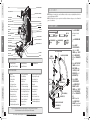
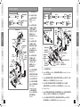
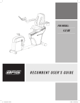
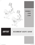
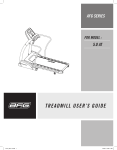
AFG SERIES
FOR MODEL :
2.0 AS
HOME GYM ASSEMBLY
AND USER’S GUIDE
2.0AS_Rev.1.5.indd 1
9/23/08 10:14:02 AM
INTRODUCTION
INTRODUCTION
IMPORTANT
PRECAUTIONS
CONGRATULATIONS and THANK YOU for your purchase of this AFG series home gym!
Whether your goal is to tone your muscles, increase your strength or simply enjoy a fuller, healthier
lifestyle, an AFG series home gym can help you attain it – adding club-quality performance to your
at-home workouts, with the ergonomics and innovative features you need to get stronger and healthier,
faster. Because we're committed to designing fitness equipment from the inside out, we use only the
highest quality components. It's a commitment we back with one of the strongest warranty packages
in the industry.
ASSEMBLY
You want exercise equipment that offers the most comfort, the best reliability and the highest quality
in its class.
BEFORE
YOU BEGIN
An AFG home gym delivers.
Assembly
5
Before You Begin
18
Conditioning Guidelines
19
Troubleshooting & Maintenance
24
Limited Warranty
26
CONTACT INFORMATION
TROUBLESHOOTING
& MAINTENANCE
4
Back Panel
2.0AS_Rev.1.5.indd 2-3
LIMITED
WARRANTY
Important Precautions
CONDITIONING
GUIDELINES
TABLE OF CONTENTS
9/23/08 10:14:03 AM
ASSEMBLY
WARNING To reduce the risk of injury to persons:
• Close supervision is necessary when this home gym is used by, on, or near children, invalids, or disabled persons.
• Use this appliance (or home gym) only for its intended use as described in this manual. Do not use attachments not
recommended by the manufacturer.
BEFORE
YOU BEGIN
• Never drop or insert any object into any opening.
• If you experience any kind of pain, including but not limited to chest pains, nausea, dizziness, or shortness of breath,
stop exercising immediately and consult your physician before continuing.
• Do not wear clothes that might catch on any part of the home gym.
• Always wear athletic shoes while using this equipment.
• Do not jump on the home gym.
• At no time should more than one person be on home gym while in operation.
• The home gym should not be used by persons weighing more than 300 pounds. Failure to comply will void the
warranty.
• The home gym is intended for in-home use only. Do not use this home gym in any commercial, rental, school or
institutional setting. Failure to comply will void the warranty.
CONDITIONING
GUIDELINES
• Do not use outdoors.
INTRODUCTION
IMPORTANT
PRECAUTIONS
Read all instructions before using this home gym. Basic precautions should always be followed, including the
following: Read all instructions before using this home gym. It is the responsibility of the owner to ensure that
all users of this home gym are adequately informed of all warnings and precautions. If you have any questions
after reading this manual, contact customer service at the number listed on the back cover of this manual.
WARNING
During the assembly process there are several areas that special attention must be paid. It is very important
to follow the assembly instructions correctly and to make sure all parts are firmly tightened. If the assembly
instructions are not followed correctly, the home gym could have frame parts that are not tightened and will
seem loose and may cause irritating noises. There should be no side-to-side play in the frame uprights. If
there is any play in these areas, the home gym has not been properly assembled. To prevent damage to the
home gym, the assembly instructions must be reviewed and corrective actions should be taken.
ASSEMBLY
IMPORTANT
PRECAUTIONS
SAVE THESE INSTRUCTIONS
IMPORTANT: READ THESE SAFETY INSTRUCTIONS BEFORE USE!
UNPACKING
Place the home gym carton on a level flat surface. It is recommended that you place a protective covering
on your floor. Take CAUTION when handling and transporting this unit. Never open box when it is on its
side. Unpack the unit where it will be used. FAILURE TO FOLLOW THESE INSTRUCTIONS COULD RESULT IN
INJURY!
BEFORE
YOU BEGIN
FOR HOUSEHOLD USE ONLY
ASSEMBLY
Before proceeding, find your home gym’s serial number
and model name located on the left rear side of the base
frame and enter it in the space provided below.
CONDITIONING
GUIDELINES
INTRODUCTION
I M P O R TA N T SAFETY INSTRUCTIONS
enter your serial number and
model name in the boxes below:
MODEL NAME:
* Refer to the serial number and model name when calling for service.
* Also enter this serial number on your Warranty Card.
LIMITED
WARRANTY
2.0AS_Rev.1.5.indd 4-5
LIMITED
WARRANTY
TROUBLESHOOTING
& MAINTENANCE
At NO time should pets or children under the age of 12 be closer to the home gym than 10 feet.
At NO time should children under the age of 12 use the home gym.
Children over the age of 12 should not use the home gym without adult supervision.
TROUBLESHOOTING
& MAINTENANCE
SERIAL NUMBER:
9/23/08 10:14:05 AM
DUAL FLOATING PULLEY BRACKET
WEIGHT SHROUD
LAT PULLDOWN BAR
LARGE “O” RING
CABLE “C”
CENTER SUPPORT FRAME
PRE-ASSEMBLY
note: During each assembly step, ensure that ALL nuts and bolts are in place and partially threaded in before
completely tightening any ONE bolt.
NOTE: A light application of grease may aid in the installation of hardware. Any grease, such as lithium bike
grease is recommended.
BAYONET
WEIGHT SELECTION PIN
HANDLES
HARDWARE BAG 1 CONTENTS :
BOLT (A)
75 mm
Qty: 2
RADIAL ARM ADJUSTMENT PIN
SEAT BACK PAD
RIGHT SUPPORT FRAME
SEAT BACK ADJUSTMENT KNOB
SINGLE FLOATING PULLEY BRACKET
ASSEMBLY
BICEP CURL BAR
SEAT BOTTOM PAD
FLAT WASHER (C)
Qty: 4
BOLT (B)
95 mm
Qty: 4
ARC WASHER (D)
Qty: 8
SEAT ASSEMBLY SAFETY PIN
NYLON
NUT (E)
Qty: 6
SEAT WELDMENT
LEG EXTENSION/CURL DOWN TUBE
ADJUSTMENT BAR
SEAT HEIGHT ADJUSTMENT KNOB
LEFT SUPPORT FRAME
BASE FRAME
FOAM ROLLERS
ADJUSTABLE FOOTPLATE
BEFORE
YOU BEGIN
CABLE “D”
TOOLS INCLUDED
19 mm Flat Wrench
13 mm/17 mm Flat Wrench
4 mm Allen Wrench
5 mm Allen Wrench
6 mm Allen Wrench
1 Center Support Frame
1 Seat Weldment
2 Weight Shrouds
2 Guide Rods
1 Weight Selection Pin
1 5 lb. Increment Weight
1 Dual Floating Pulley Bracket
1 Set Of Weight Plate Decals
1 Center Connection Tube
1 Lower Connection Tube
1 Lower Pulley Bracket
2 Upgrade Spacers
2 Accent Pieces
2 Single Floating Pulley Bracket
1 Upper Pulley Assembly
1 Seat Bottom Pad
1 Nylon Ankle Strap
2 Handles
1 Lat Pulldown Bar
10 Hardware Bags
2 Foam Rollers
1 Seat Head Pad
2 Side Connection Tubes
1 Upper Mounting Bracket
1 Lower Mounting Bracket
RIGHT SUPPORT FRAME
CENTER
SUPPORT FRAME
CONDITIONING
GUIDELINES
TROUBLESHOOTING
& MAINTENANCE
LIMITED
WARRANTY
If you have questions or if there are any missing parts, contact Customer Tech Support.
Contact information is located on the back panel of this manual.
2.0AS_Rev.1.5.indd 6-7
For a complete exploded diagram, visit us at www.advancedfitnessgroup.com
B Open HARDWARE BAG
1.
C Attach RIGHT
SUPPORT FRAME to
right side of base
frame using 2 BOLTS
(B), 4 ARC washers
(D) and 2 NYLON nuts
(E).
D Attach Left SUPPORT
FRAME to left side of
base frame using
2 BOLTS (B), 4 ARC
washers (D) and 2
NYLON nuts (E).
PARTS INCLUDED
1 Bayonet
1 Bicep Curl Bar
1 Seat Back Pad
1 Base Frame
1 Left Support Frame
1 Right Support Frame
1 Seat Back Adjustment Bar
1 Radial Arm Assembly
1 Exercise Flipbook
2 Seat Adjustment Pins
1 Leg Roller Support Tube
1 Water Bottle Holder
1 Seat Bottom Adjustment Bar
A Place base frame
on floor in desired
location.
ASSEMBLY
SEAT HEAD PAD
ASSEMBLY STEP 1
BEFORE
YOU BEGIN
ACCENT PIECE
BOLT (A)
BOLT (B)
ARC WASHER (D)
FLAT
WASHER (C)
ARC WASHER (D)
BASE FRAME
NYLON NUT (E)
LOWER PULLEY BRACKET
FLAT WASHER (C)
CONDITIONING
GUIDELINES
RADIAL ARM ASSEMBLY
CABLE “B”
E Attach center
SUPPORT FRAME
and LOWER PULLEY
BRACKET to BASE
frame using 2 BOLTS
(A), 4 flat washers
(C) and 2 NYLON nuts
(E).
NOTE: Ensure that
the Lower Pulley
bracket is positioned
as shown in diagram.
TROUBLESHOOTING
& MAINTENANCE
IMPORTANT
PRECAUTIONS
GUIDE ROD
WATER BOTTLE HOLDER
INTRODUCTION
LEFT SUPPORT FRAME
IMPORTANT
PRECAUTIONS
UPPER PULLEY ASSEMBLY
NYLON NUT (E)
LIMITED
WARRANTY
INTRODUCTION
CABLE “A”
9/23/08 10:14:12 AM
ARC WASHER (D)
NYLON NUT (E)
ASSEMBLY
ARC WASHER (D)
BOLT (F)
UPPER PULLEY
ASSEMBLY
NUT (E)
ARC WASHER (D)
BOLT (A)
BEFORE
YOU BEGIN
LEFT SUPPORT
FRAME
LARGE
“O” RING
RIGHT
SUPPORT
FRAME
CENTER
SUPPORT FRAME
CONDITIONING
GUIDELINES
SEAT
WELDMENT SET
TROUBLESHOOTING
& MAINTENANCE
SEAT SAFETY PIN
LIMITED
WARRANTY
2.0AS_Rev.1.5.indd 8-9
D Attach UPPER PULLEY
ASSEMBLY to RIGHT
MAIN SUPPORT FRAME
using 2 BOLTS (B), 4
ARC WASHERS (D) and 2
NYLON NUTS (E).
E Attach UPPER PULLEY
ASSEMBLY to LEFT
SUPPORT FRAME using
2 BOLTS (B), 4 ARC
WASHERS (D), and 2
NYLON NUTS (E).
F Install SEAT WELDMENT
SET onto posts on
CENTER SUPPORT FRAME
as shown in diagram, and
insert SEAT SAFETY PIN.
SEAT
ADJUSTMENT
PIN
G Install SEAT ADJUSTMENT
PIN into SEAT WELDMENT
SET as shown in
diagram. (Fully thread
into SEAT WELDMENT
SET after SEAT BOTTOM
ADJUSTMENT BAR is
installed.)
BOLT (H)
20 mm
Qty: 4
FLAT
WASHER (I)
Qty: 2
BOLT (J)
83 mm
Qty: 2
STEP 3-B: INSTALLING THE STOPPER:
RADIAL ARM ASSEMBLY
STOPPER
BOLT (G)
92 mm
Qty: 1
CENTER
SUPPORT
FRAME
NYLON
NUT (K)
Qty: 1
IMPORTANT
PRECAUTIONS
C Attach upper PULLEY
assembly to CENTER
SUPPORT FRAME using
4 bolts (F) and 4 ARC
washers (D) and 2
NYLON NUTS (E). Tighten
this hardware.
BOLT (F)
25 mm
Qty: 2
NYLON
NUT (E)
Qty: 2
LOCK
WASHER (L)
Qty: 2
FLAT
WASHER (C)
LOCK
WASHER (L)
ASSEMBLY
LARGE “O” RING
Qty: 1
FLAT
WASHER (C)
Qty: 10
BOLT (F)
FLAT WASHER (C)
NYLON NUT (E)
NYLON NUT (K)
NYLON NUT (E)
CENTER
CONNECTION
TUBE
BOLT (J)
LEG ROLLER
SUPPORT TUBE
RADIAL ARM
ASSEMBLY
LEFT
CONNECTION
TUBE
BEFORE
YOU BEGIN
IMPORTANT
PRECAUTIONS
BOLT (F)
90 mm
Qty: 2
B Slide LARGE “O” RING
onto CENTER SUPPORT
FRAME as shown in
diagram.
FLAT WASHERS (C)
BOLT (H)
RIGHT CONNECTION TUBE
FLAT WASHER (I)
BOLT (J)
BOLT (G)
LOWER
CONNECTION TUBE
CONDITIONING
GUIDELINES
ARC WASHER (D)
Qty: 12
BOLT (B)
95 mm
Qty: 4
HARDWARE BAG 3 CONTENTS :
A Open HARDWARE BAG 3.
B Remove STOPPER from front side of RADIAL ARM ASSEMBLY and reinstall on back side.
Tighten both STOPPERS.
C Attach RADIAL ARM ASSEMBLY to CENTER SUPPORT FRAME using 2 BOLTS (F), 2 LOCK
WASHERS (L) and 2 FLAT WASHERS (C). Tighten this hardware.
TROUBLESHOOTING
& MAINTENANCE
A Open HARDWARE BAG 2.
HARDWARE BAG 2 CONTENTS :
NYLON
NUT (E)
Qty: 6
INTRODUCTION
ASSEMBLY STEP 3
D Attach RIGHT SIDE CONNECTION TUBE to SEAT WELDMENT SET and to LOWER
CONNECTION TUBE using 2 BOLTS (H) and 2 FLAT WASHERS (C), as shown in diagram.
E Repeat on left side.
F Attach CENTER CONNECTION TUBE to SEAT WELDMENT SET and to LOWER CONNECTION
TUBE using 2 BOLTS (J), 4 FLAT WASHERS (C) and 2 NYLON NUTS (E).
G Attach LEG ROLLER SUPPORT TUBE to LOWER CONNECTION TUBE using 1 BOLT (G), 2
FLAT WASHERS (I) and 1 NYLON NUT (K). Tighten all hardware in Step 3.
LIMITED
WARRANTY
INTRODUCTION
A S S E M B LY S T E P 2
9/23/08 10:14:19 AM
HARDWARE BAG 5 CONTENTS :
SEAT HEAD PAD
BOLT (F)
FLAT WASHER (C)
ASSEMBLY
CENTER SUPPORT
FRAME
WATER
BOTTLE
HOLDER
FLAT WASHER (C)
SEAT BACK ADJUSTMENT BAR
SEAT BACK PAD
SEAT BOTTOM PAD
BEFORE
YOU BEGIN
NYLON
NUT (E)
SEAT BOTTOM
ADJUSTMENT BAR
BOLT (M)
CONDITIONING
GUIDELINES
A Open HARDWARE BAG 4.
LEG ROLLER
SUPPORT TUBE
SEAT BACK
ADJUSTMENT PIN
LEG ROLLER
CHROME WASHER (U)
LOCK WASHER (L)
BOLT (F)
B Attach SEAT HEAD PAD to CENTER
SUPPORT FRAME using 4 BOLTS (F) and 4 FLAT WASHERS (C), as shown in diagram.
C Install SEAT BACK ADJUSTMENT PIN in CENTER SUPPORT FRAME. (Fully thread into
CENTER SUPPORT FRAME after SEAT BACK ADJUSTMENT BAR is installed.)
TROUBLESHOOTING
& MAINTENANCE
D Attach SEAT BACK PAD to SEAT BACK ADJUSTMENT BAR using 4 BOLTS (F) and 4 FLAT
WASHERS (C), and insert into CENTER SUPPORT FRAME as shown in diagram.
E Attach SEAT BOTTOM PAD to SEAT BOTTOM ADJUSTMENT BAR using 2 BOLTS (M) and 4
FLAT WASHERS (C) and 2 NYLON NUTS (E), and insert into SEAT WELDMENT as shown in
diagram.
LIMITED
WARRANTY
F Install FOAM ROLLERS onto LEG ROLLER SUPPORT TUBE using 2 BOLTS (F), 2 LOCK
WASHERS (L) and 2 CHROME WASHERS (U), as shown in diagram.
B Attach LOWER MOUNTING BRACKET (after
removing pre-installed guide rod bolts) to BASE
FRAME in desired location, using 2 BOLTS (P),
4 FLAT WASHERS (C) and 2 NYLON NUTS (E).
NOTE: Refer to page 25 for mounting positions.
D Slide 1 UPGRADE SPACER and then slide 1
RUBBER BUMPER onto each guide rod, as
shown in diagram.
E Install each WEIGHT PLATE onto guide rod as
shown in diagram. Ensure than the weight pin
selector slot is positioned downward and in
same direction.
2.0AS_Rev.1.5.indd 10-11
RUBBER
BUMPER
Qty: 2
BOLT (Q)
40 mm
Qty: 2
BOLT (P)
70 mm
Qty: 2
UPPER MOUNTING BRACKET
FLAT WASHER (I)
BOLT (Q)
NYLON NUT (K)
BOLT (O)
FLAT
WASHER (I)
UPPER
PULLEY
ASSEMBLY
FLAT
WASHER (C)
NYLON NUT (E)
RUBBER
BUMPER
BOLT (P)
GUIDE
ROD
BAYONET
WEIGHT
PLATES
UPGRADE
SPACER
F Install BAYONET onto GUIDE RODS as shown in
diagram.
G Re-install guide rod bolts into lower
mounting bracket.
H Install UPPER MOUNTING BRACKET to top of
GUIDE RODS, as shown in diagram, using 2
BOLTS (Q), 4 FLAT WASHERS (I) and 2 NYLON
NUTS (K).
LOWER MOUNTING
BRACKET
BASE FRAME
FLAT WASHER (C)
NYLON NUT (E)
I
Attach UPPER MOUNTING BRACKET to UPPER PULLEY ASSEMBLY using 2 BOLTS (O), 4
FLAT WASHERS (C), and 2 NYLON NUTS (E).
NOTE: Ensure that the UPPER MOUNTING BRACKET’s position corresponds to the position
of the LOWER MOUNTING BRACKET before securing it to the UPPER PULLEY ASSEMBLY.
j
Tighten all hardware.
G Attach WATER BOTTLE HOLDER to CENTER SUPPORT FRAME using 2 BOLTS (N).
H Tighten all hardware in Step 4.
NYLON
NUT (K)
Qty: 2
A Open HARDWARE BAG 5.
C Position each GUIDE ROD so that the mounting
holes are in the upper position, and insert
GUIDE RODS into corresponding sleeves in
LOWER MOUNTING BRACKET.
BOLT (F)
FLAT
WASHER (C)
FLAT WASHER (I)
Qty: 4
BOLT (O)
100 mm
Qty: 2
CHROME WASHER (U)
Qty: 2
BOLT (N)
NYLON
NUT (E)
Qty: 4
IMPORTANT
PRECAUTIONS
IMPORTANT
PRECAUTIONS
BOLT (N)
25 mm
Qty: 2
BOLT (M)
65 mm
Qty: 2
FLAT WASHER (C)
Qty: 8
LOCK WASHER (L)
Qty: 2
ASSEMBLY
BOLT (F)
25 mm
Qty: 10
BEFORE
YOU BEGIN
NYLON
NUT (E)
Qty: 2
TROUBLESHOOTING
& MAINTENANCE
FLAT WASHER (C)
Qty: 12
CONDITIONING
GUIDELINES
HARDWARE BAG 4 CONTENTS :
10
INTRODUCTION
ASSEMBLY STEP 5 (1 5 0 lbs. Weight Stack)
11
LIMITED
WARRANTY
INTRODUCTION
A S S E M B LY S T E P 4
9/23/08 10:14:31 AM
B Attach LOWER MOUNTING BRACKET (after
removing pre-installed guide rod bolts) to BASE
BOLT (Q)
FRAME in desired location, using 2 BOLTS (P), 4
FLAT WASHERS (C) and 2 NYLON NUTS (E).
NOTE: Refer to page 25 for mounting positions.
ASSEMBLY
NYLON NUT (K)
BOLT (O)
BOLT (Q)
40 mm
Qty: 2
BOLT (P)
70 mm
Qty: 2
A BRACKET
Open HARDWARE BAG 5.
UPPER MOUNTING
FLAT WASHER (I)
RUBBER
BUMPER
Qty: 2
UPPER MOUNTING BRACKET
CONDITIONING
GUIDELINES
BOLT (P)
BAYONET
D SlideWEIGHT
1 RUBBER BUMPER onto each guide rod,
PLATESin diagram.
as shown
E Install each WEIGHT PLATE onto guide rod as
shown
in diagram. Ensure than the weight pin
UPGRADE
selector
slot is positioned downward and in
SPACER
same direction.
INTRODUCTION
C Remove THREADED SCREW and NUT
from other end of CABLE A.
DUAL FLOATING
PULLEY BRACKET
SINGLE FLOATING
PULLEY BRACKET
CABLE A
CABLE A
BOLT (Q)
NYLON NUT (K)
E After CABLE A routing is complete,
install THREADED SCREW and NUT
onto cable end and thread through
WEIGHT SELECTION PIN tether into
BAYONET.
NOTE: Always maintain at least 1/2”
of CABLE A SCREW threaded into
BAYONET for safety.
BOLT (O)
FLAT
WASHER (I)
UPPER
PULLEY
ASSEMBLY
FLAT
WASHER (C)
NYLON NUT (E)
D Route CABLE A through pulleys as
shown in diagram.
NOTE: DUAL FLOATING PULLEY
BRACKET must be installed after
CABLE A is routed through first pulley.
GUIDE
ROD
BAYONET
WEIGHT
PLATES
BAYONET
RUBBER
BUMPER
BOLT (P)
F Install BAYONET onto GUIDE RODS as shown in
diagram.
G Re-install guide rod bolts into lower
TROUBLESHOOTING
& MAINTENANCE
LOWER
MOUNTING bracket.
mounting
BRACKET
BASE FRAME
H WASHER
Install(C)
UPPER MOUNTING BRACKET to top of
FLAT
NYLON GUIDE
NUT (E) RODS, as shown in diagram, using 2
LOWER MOUNTING
BRACKET
BASE FRAME
FLAT WASHER (C)
NYLON NUT (E)
CABLE A
WEIGHT SELECTION
PIN TETHER
TROUBLESHOOTING
& MAINTENANCE
BEFORE
YOU BEGIN
FLAT
WASHER (C)
NYLON NUT (E)
RUBBER
BUMPER
C Position each GUIDE ROD so that the mounting
holesGUIDE
are in the upper position, and insert
GUIDEROD
RODS into corresponding sleeves in
LOWER MOUNTING BRACKET.
B Install SINGLE FLOATING PULLEY
BRACKET onto one end of CABLE A.
FLAT WASHER (I)
FLAT
WASHER (I)
UPPER
PULLEY
ASSEMBLY
CABLE A
Qty: 1
IMPORTANT
PRECAUTIONS
IMPORTANT
PRECAUTIONS
BOLT (O)
100 mm
Qty: 2
NYLON
NUT (K)
Qty: 2
ASSEMBLY
FLAT WASHER (I)
Qty: 4
BEFORE
YOU BEGIN
NYLON
NUT (E)
Qty: 4
CONDITIONING
GUIDELINES
FLAT WASHER (C)
Qty: 8
A Open HARDWARE BAG 6.
HARDWARE BAG 6 CONTENTS :
HARDWARE BAG 5 CONTENTS :
BAYONET
BOLTS (Q), 4 FLAT WASHERS (I), and 2 NYLON
NUTS (K).
LIMITED
WARRANTY
12
2.0AS_Rev.1.5.indd 12-13
I
Attach UPPER MOUNTING BRACKET to UPPER PULLEY ASSEMBLY using 2 BOLTS (O), 4
FLAT WASHERS (C), and 2 NYLON NUTS (E).
NOTE: Ensure that the UPPER MOUNTING BRACKET’s position corresponds to the position
of the LOWER MOUNTING BRACKET before securing it to the UPPER PULLEY ASSEMBLY.
j
Tighten all hardware.
13
LIMITED
WARRANTY
INTRODUCTION
ASSEMBLY STEP 6
A S S E M B LY S T E P 5 ( 2 0 0 l b s . W e i g h t S t a c k )
9/23/08 10:14:44 AM
INTRODUCTION
ASSEMBLY STEP 8
HARDWARE BAG 7 CONTENTS :
HARDWARE BAG 8 CONTENTS :
CABLE C
Qty: 1
CABLE B
Qty: 1
WASHER
NUT
BALL STOP
CABLE B
BALL STOP
“O” RING
SCREW
CLEVIS
CABLE B
WASHER
ASSEMBLY
SCREW
WASHER
UPPER PULLEY
ASSEMBLY
CABLE C
WASHER
NUT
ASSEMBLY
IMPORTANT
PRECAUTIONS
“O” RING
SINGLE FLOATING
PULLEY BRACKET
CLEVIS
IMPORTANT
PRECAUTIONS
INTRODUCTION
A S S E M B LY S T E P 7
HOOK
LAT BAR
LAT BAR
HOOK
BEFORE
YOU BEGIN
HANDLE
SINGLE FLOATING
PULLEY BRACKET
B Remove NUT, WASHERS, SCREW, HOOK, CLEVIS and BALL STOP from one end of CABLE B.
TROUBLESHOOTING
& MAINTENANCE
C Route CABLE B through the pulley system in the RADIAL ARM ASSEMBLY as shown in
diagram.
NOTE: Thread cable through SINGLE FLOATING PULLEY between each arm of the RADIAL
ARM ASSEMBLY.
D After CABLE B routing is complete replace BALL STOP, CLEVIS, HOOK, SCREW, WASHERS
and NUT on end of cable.
NOTE: Ensure the “O” RINGS are positioned at the ends of CABLE B against the BALL
STOPS.
E Hook HANDLES on to cable using the 2 HOOKS.
A Open HARDWARE BAG 8.
B Remove NUT, WASHERS, SCREW, HOOK, CLEVIS and BALL STOP from one end of CABLE C.
TROUBLESHOOTING
& MAINTENANCE
CONDITIONING
GUIDELINES
A Open HARDWARE BAG 7.
CONDITIONING
GUIDELINES
RADIAL
ARM ASSEMBLY
C Install CABLE C as shown in diagram. Ensure that the SINGLE FLOATING PULLEY BRACKET
is installed after passing through two upper pulleys.
D After CABLE C routing is complete replace BALL STOP, CLEVIS, HOOK, SCREW, WASHERS
and NUT on end of cable.
NOTE: Ensure the “O” RINGS are positioned at the ends of CABLE C against the BALL
STOPS.
LIMITED
WARRANTY
E Install lat bar using the 2 HOOKS.
14
2.0AS_Rev.1.5.indd 14-15
15
LIMITED
WARRANTY
BEFORE
YOU BEGIN
HANDLE
9/23/08 10:14:56 AM
INTRODUCTION
ASSEMBLY STEP 10
HARDWARE BAG 9 CONTENTS :
HARDWARE BAG 10 CONTENTS :
CABLE D
Qty: 1
BOLT (R)
10 mm
Qty: 8
IMPORTANT
PRECAUTIONS
DUAL FLOATING
PULLEY BRACKET
CABLE D
CABLE D
IMPORTANT
PRECAUTIONS
INTRODUCTION
A S S E M B LY S T E P 9
WEIGHT
SHROUD
ASSEMBLY
ASSEMBLY
UPPER MOUNTING
BRACKET
SINGLE FLOATING
PULLEY BRACKET
BOLT (R)
BEFORE
YOU BEGIN
BEFORE
YOU BEGIN
CONDITIONING
GUIDELINES
A Open HARDWARE BAG 9.
LOWER MOUNTING
BRACKET
C Install CABLE D as shown in diagram.
TROUBLESHOOTING
& MAINTENANCE
D After CABLE D routing is complete replace BALL STOP, CLEVIS, HOOK, SCREW, WASHERS
and NUT on end of cable.
NOTE: Ensure the “O” RING is positioned at the end of CABLE D against the BALL STOP.
E Attach CABLE D to PRE-ATTACHED LEG EXTENSION CABLE.
WEIGHT
SHROUD
TROUBLESHOOTING
& MAINTENANCE
B Remove NUT, WASHERS, SCREW, HOOK, CLEVIS and BALL STOP from the end of CABLE D.
A Open HARDWARE BAG 10.
B Install WEIGHT SHROUDS as shown in diagram, using 8 BOLTS (R).
LIMITED
WARRANTY
YOU’RE FINISHED!
16
2.0AS_Rev.1.5.indd 16-17
17
LIMITED
WARRANTY
CONDITIONING
GUIDELINES
PRE-ATTACHED LEG EXTENSION CABLE
9/23/08 10:15:07 AM
ASSEMBLY
The key to reaping these benefits is to develop an exercise habit. Your new home gym will help you eliminate
obstacles that prevent you from exercising. Inclement weather and darkness won't interfere with your
workout when you use your home gym in the comfort of your home. This guide provides you with basic
information for using and enjoying your new machine.
Back
1 foot
Location of the home gym
IMPORTANT
PRECAUTIONS
• Improved Muscle Tone and Strength
• Increased Daily Energy Levels
• A Healthier Heart
• Weight Loss
The American Heart Association recommends that you exercise at least 3 to 4 days per week to maintain fitness.
If you have other goals such as weight or fat loss, you will achieve your goal faster with more frequent exercise.
Whether it’s 3 days or 6 days, remember that your ultimate goal should be to make exercise a lifetime habit.
Many people are successful staying with a fitness program if they set aside a specific time of day to exercise.
It doesn’t matter whether it’s in the morning before breakfast, during lunch hour or while watching the evening
news. What’s more important is that it’s a time that allows you to keep a schedule, and a time when you won’t
be interrupted. To be successful with your fitness program, you have to make it a priority in your life. So decide
on a time, pull out your day planner and pencil in your exercise times for the next month!
ASSEMBLY
Here are just a few of the health benefits of exercise:
HOW OFTEN? (Frequency of Workouts)
HOW LONG? (Duration of Workouts)
For aerobic exercise benefits, it’s recommended that you exercise from between 24 and 60 minutes per session.
But start slowly and gradually increase your exercise times. If you’ve been sedentary during the past year, it may
be a good idea to keep your exercise times to as little as 5 minutes initially. Your body will need time to adjust
to the new activity. If your goal is weight loss, a longer exercise session at lower intensities has been found to
be most effective.
BEFORE
YOU BEGIN
HOW HARD? (Intensity of Workouts)
3 feet
3 feet
CONDITIONING
GUIDELINES
Front
3 feet
How hard you workout is also determined by your goals. If you use your home gym to prepare for a 5K run, you will
probably work out at a higher intensity than if your goal is general fitness. Regardless of your long term goals,
always begin an exercise program at low intensity. Aerobic exercise does not have to be painful to be beneficial!
There are two ways to measure your exercise intensity. The first is by monitoring your heart rate, and the second
is by evaluating your perceived exertion level (this is simpler than it sounds!).
CONDITIONING
GUIDELINES
IMPORTANT
PRECAUTIONS
and sustaining an exercise program! Your home gym is a tremendously effective tool for achieving your
personal fitness goals. Regular use of your home gym can improve the quality of your life in so many
ways.
Always consult your physician before beginning an exercise program.
BEFORE
YOU BEGIN
CONGRATULATIONS! on choosing your home gym. You’ve taken an important step in developing
Place the home gym on a level surface. There should be 1 foot of
clearance behind the home gym, 3 feet on each side and 3 feet in front.
Do not place the home gym in any area that will block any vent or air
openings. The home gym should not be located outdoors.
INTRODUCTION
CONDITIONING GUIDELINES
PERCEIVED EXERTION LEVEL
TROUBLESHOOTING
& MAINTENANCE
Ensure that the seat assembly safety pin is fully inserted before using the home
gym. Failure to do so may result in injury!
PROPER USAGE
Make sure to follow the MAINTENANCE schedule in this manual. Stop your workout immediately if you feel pain,
faint, dizzy or are short of breath.
WARNING
LIMITED
WARRANTY
18
2.0AS_Rev.1.5.indd 18-19
Do not operate the home gym if there is any noticeable damage to the cables
or pulleys. If any damage is noticeable, contact customer tech support at the
number located on the back panel of this manual.
TROUBLESHOOTING
& MAINTENANCE
WARNING
SEAT ASSEMBLY PIN
A simple way to gauge your exercise intensity is to evaluate your perceived exertion level. While exercising, if you
are too winded to maintain a conversation without gasping, you are working out too hard. A good rule of thumb
is to work to the point of exhilaration, not exhaustion. If you cannot catch your breath, it’s time to slow down.
Always be aware of these warning signs of overexertion.
General Strength Training Guidelines
• It is recommended that you perform at least 10-15 minutes of cardiovascular exercise before beginning your
strength routine in order to warm the muscles, increase the heart rate, and prepare your body for strength
training.
• Always raise and lower the weight in a smooth, slow, and controlled motion.
• Try not to hold your breath during strength training exercises. It is recommended that you exhale as you raise
the weight and inhale as you lower the weight.
• It is recommended that each muscle group be allowed to rest 48 hours between strength training.
• Complete each strength routine with a few simple stretches to maintain flexibility, and allow your body to
cool-down after your session.
19
LIMITED
WARRANTY
INTRODUCTION
B E F O R E Y O U BEGIN
9/23/08 10:15:09 AM
INTRODUCTION
INTRODUCTION
TA R G E T H E A R T R AT E Z O N E C H A R T
TIPS
STRETCHING
STRETCH FIRST
%
15
12
0
0
BEFORE
YOU BEGIN
AGE
14
6
14
3
T A 139 1
35
R
13
11
1
7
G
11
E
4
T
11
1
10
8
1. STANDING CALF MUSCLE STRETCH
12
8
12
4
Z O 120
10
5
NE
10
2
9
9
20
25
30
35
40
45
50
55
97
60
11
6
Stand near a wall with the toes of tour left foot about 18" from the wall, and
the right foot about 12" behind the other foot. Lean forward, pushing against
the wall with your palms. Keep your heels flat and hold this position for a
count of 15 seconds. Make sure that you do not bounce while stretching.
Repeat on the other side.
BEFORE
YOU BEGIN
ASSEMBLY
60
%
93
65
2. STANDING QUADRICEPS STRETCH
CONDITIONING
GUIDELINES
Using a wall to provide balance, grasp your left ankle
with your left hand and hold your foot against the back
of your thigh for 15 seconds. Repeat with your right
ankle and hand.
CONDITIONING
GUIDELINES
75
ASSEMBLY
0%
example:
Always consult your physician before beginning an exercise program.
LIMITED
WARRANTY
20
2.0AS_Rev.1.5.indd 20-21
3. SITTING HAMSTRING & LOWER BACK MUSCLE STRETCH
TROUBLESHOOTING
& MAINTENANCE
TROUBLESHOOTING
& MAINTENANCE
For a 42-year-old user: Find age along the bottom of the chart (round to 40), follow age column up to
the target zone bar. Results: 60% of maximum Heart Rate = 108 Beats Per Minute, 75% of maximum
Heart Rate = 135 Beats Per Minute.
Sit on the floor with your legs together and straight out in front of you. Do
not lock your knees. Extend your fingers towards your toes and hold for a
count of 15 seconds. Make sure that you do not bounce while stretching. Sit
upright again. Repeat one time.
21
LIMITED
WARRANTY
10
Before using your product, it is best to take a few minutes doing a few gentle stretching exercises.
Stretching prior to exercise will improve flexibility and reduce chances of exercise related injury. Ease into
each of these stretches with a slow gentle motion. Do not stretch to the point of pain. Make sure not to
bounce while doing these stretches.
BEATS PER MINUTE
IMPORTANT
PRECAUTIONS
Target Heart Rate Zone tells you
the number of times per minute
your heart needs to beat to
achieve a desired workout effect.
It is represented as a percentage
of the maximum number of times
your heart can beat per minute.
Target Zone will vary for each
individual, depending on age,
current level of conditioning,
and personal fitness goals. The
American Heart Association
recommends working-out at a
Target Heart Rate Zone of between
60% and 75% of your maximum
heart rate. A beginner will want to
workout in the 60% range while
a more experienced exerciser will
want to workout in the 70-75%
range. See chart for reference.
IMPORTANT
PRECAUTIONS
What is Target Heart Rate Zone?
9/23/08 10:15:10 AM
INTRODUCTION
INTRODUCTION
TIPS
THE IMPORTANCE OF WARM UP & COOL DOWN
IMPORTANT
PRECAUTIONS
WARM UP
DATE
EXERCISE
SET 1
WEIGHT
REPS
SET 2
WEIGHT
RE P S
SET 3
WEIGHT
REPS
DATE
EXERCISE
SET 1
WEIGHT
REPS
SET 2
WEIGHT
RE P S
SET 3
WEIGHT
REPS
DATE
EXERCISE
SET 1
WEIGHT
REPS
SET 2
WEIGHT
RE P S
SET 3
WEIGHT
REPS
IMPORTANT
PRECAUTIONS
DAILY LOG SHEETS
Always perform 10-15 minutes of aerobic activity before beginning your strength training session. This
warm-up will limber your muscles and prepare them for more strenuous exercise. Make sure that you warmup on your product at a slow pace. The warm up should gradually increase your heart rate into your heart
rate training zone and increase core body temperature.
COOL DOWN
ACHIEVING YOUR FITNESS GOALS
BEFORE
YOU BEGIN
An important step in developing a long term fitness program is to determine your goals. Is your primary
goal for exercising to lose weight? Improve muscle tone and/or strength? Reduce stress? Knowing what
your goals are will help you develop a more successful exercise program. Below are some common exercise
goals:
ASSEMBLY
BEFORE
YOU BEGIN
TIPS
TROUBLESHOOTING
& MAINTENANCE
LIMITED
WARRANTY
22
2.0AS_Rev.1.5.indd 22-23
CONDITIONING
GUIDELINES
If possible try to define your personal goals in precise, measurable terms, and then put your goals in writing.
The more specific you can be, the easier it will be to track your progress. If your goals are long term, divide
them up into monthly and weekly segments. Longer term goals can lose some of the immediate motivation
benefits. Short term goals are easier to achieve.
TROUBLESHOOTING
& MAINTENANCE
CONDITIONING
GUIDELINES
• Weight Loss - lower intensity, longer duration workouts
• Improve Body Shape and Tone - interval workouts, alternate between hi and low intensities
• Increased Energy Level - more frequent daily workouts
• Improved Sports Performance - high intensity workouts
23
LIMITED
WARRANTY
ASSEMBLY
Never stop exercising suddenly! A cool-down period of 3-5 minutes allows your heart to readjust to the
decreased demand. Your cool-down period should consist of repeating the stretching exercises listed above
to loosen and relax your muscles.
9/23/08 10:15:12 AM
PROBLEM: Weight selector pin cannot be inserted.
SOLUTION: Verify the following:
BEFORE
YOU BEGIN
ARE THE HOLES ALIGNED THROUGH THE WEIGHT PLATE AND BAYONET?
If yes:
• Verify that the selector pin isn’t bent or damaged.
If no:
• Adjust threaded bolt on top plate so that the holes in the bayonet align with the weight plate.
NOTE: Always maintain at least ½˝ of weight cable screw threaded into bayonet for safety.
INTRODUCTION
IMPORTANT
PRECAUTIONS
EVERY WEEK
• Lubricate guide rods with a spray or gel silicone lubricant.
• Inspect cable ends and cable insulation for damage.
EVERY MONTH - IMPORTANT!
• Inspect all frame bolts and tighten as needed.
Please contact AFG with questions about applying lubricant to your home gym.
ADJUSTING CABLE TENSION
Regularly check the cable tension of your home gym. If excessive slack
exists adjust cable tension by removing the pulley bolts and moving
one or both pulleys to the inner mounting position in the dual floating
pulley bracket and then reinstalling the pulley bolts. Cable tension
may also be adjusted using the threaded cable screw on single pulley
bracket and weight stack. Twist threaded screw to adjust tension and
then tighten lock nut.
NOTE: Always maintain at least ½˝ of threaded bolt in bayonet.
TWIST SCREW TO
ADJUST TENSION,
THEN TIGHTEN
LOCK NUT
CABLE SCREW
AND NUT
SINGLE PULLEY
BRACKET THREAD
If the above troubleshooting section does not remedy the problem, discontinue use.
CONDITIONING
GUIDELINES
PLEASE CALL CUSTOMER TECH SUPPORT AT THE NUMBER ON THE BACK PANEL.
ASSEMBLY
ASSEMBLY
IS THERE ANY NOTICEABLE DAMAGE TO THE CABLES?
If yes:
• Contact customer tech support and replace the cable(s).
If no:
• Verify that all cables are secured into the pulleys.
• Verify that the weight stack guide rods are lubricated.
• Verify that there is no excessive slack in the cables.
NOTE: If there is excessive slack adjust cable tension (see next page)
AFTER EACH USE (DAILY)
• Wipe upholstery, hand grips, bars, and frame (if needed) with a mild cleaning solution.
INNER
MOUNTING
POSITIONS
TWIST SCREW TO
ADJUST TENSION,
THEN TIGHTEN
LOCK NUT
BEFORE
YOU BEGIN
IMPORTANT
PRECAUTIONS
PROBLEM: The cables feel rough and are noisy during use.
SOLUTION: Verify the following:
Cleanliness of your home gym and its operation environment will keep maintenance problems and service calls to a
minimum. For this reason, we recommend that the following preventive maintenance schedule be followed.
CABLE SCREW
AND NUT
BAYONET
CONDITIONING
GUIDELINES
Your home gym is designed to be reliable and easy to use. However, if you experience a problem, please reference
the troubleshooting guide listed below.
MAINTENANCE
WEIGHT PLATES
TROUBLESHOOTING
& MAINTENANCE
In order for Customer Tech Support to service your home gym they may need to ask detailed questions about the symptoms that are
occurring. Some troubleshooting questions that may be asked are:
• How long has this problem been occurring?
• Does this problem occur with every use? With every user?
• If you are hearing a noise, does it come from the front or the back? What kind of noise is it (thumping, grinding, squeaking,
chirping etc.)?
• Has the machine been lubricated and maintained per the maintenance schedule?
Answering these and other questions will give the technicians the ability to send proper replacement parts and the service necessary
to get you and your AFG home gym functioning again!
MOUNTING BRACKET POSITIONS
0º POSITION
FRONT OR BACK ACCESS
30º POSITION
FRONT OR BACK ACCESS
150º POSITION
FRONT OR BACK ACCESS
TROUBLESHOOTING
& MAINTENANCE
The following information may be asked of you when you call. Please have these items readily available:
• Model Name
• Serial Number
• Date of Purchase (receipt or credit card statement)
90º POSITION
LEFT OR RIGHT ACCESS
LIMITED
WARRANTY
This home gym allows you to choose the angle of access to the weight selection pin depending on how you install the
upper and lower mounting brackets, weight plates, and weight shrouds.
NOTE: Make sure the upper and lower mounting bracket are in the same position.
24
2.0AS_Rev.1.5.indd 24-25
25
LIMITED
WARRANTY
INTRODUCTION
T R O U B L E S HOOTING
9/23/08 10:15:13 AM
ASSEMBLY
LABOR • 1 YEAR
AFG shall cover the labor cost for the repair of the device
for a period of one year from the date of the original
purchase, so long as the device remains in the possession
of the original owner.
UPHOLSTERY • 10 YEARS
AFG warrants the upholstery for a period of ten years
from the date of original purchase, so long as the device
remains in the possession of the original owner.
BEFORE
YOU BEGIN
EXCLUSIONS AND LIMITATIONS
Who IS covered:
• The original owner and is not transferable.
INTRODUCTION
IMPORTANT
PRECAUTIONS
ASSEMBLY
PARTS • 10 YEARS
AFG warrants all original parts for a period of ten years
from the date of original purchase, so long as the device
remains in the possession of the original owner.
CONDITIONING
GUIDELINES
What IS NOT covered:
• Normal wear and tear, improper assembly or maintenance, or
installation of parts or accessories not originally intended or
compatible with the equipment as sold.
• Damage or failure due to accident, abuse, corrosion, discoloration of
paint or plastic, neglect, theft, vandalism, fire, flood, wind, lightning,
freezing, or other natural disasters of any kind, power reduction,
fluctuation or failure from whatever cause, unusual atmospheric
conditions, collision, introduction of foreign objects into the covered
unit, or modifications that are unauthorized or not recommended by
AFG.
• Incidental or consequential damages. AFG is not responsible or
liable for indirect, special or consequential damages, economic
loss, loss of property, or profits, loss of enjoyment or use, or other
consequential damages of whatsoever nature in connection with the
purchase, use, repair or maintenance of the equipment.
• Equipment used for commercial purposes or any use other than a
single family or Household, unless endorsed by AFG for coverage.
• Equipment owned or operated outside the US and Canada.
• Delivery, assembly, installation, setup for original or replacement
units or labor or other costs associated with removal or replacement
of the covered unit.
• Any attempt to repair this equipment creates a risk of injury. AFG
is not responsible or liable for any damage, loss or liability arising
from any personal injury incurred during the course of, or as a result
of any repair or attempted repair of your fitness equipment by other
than an authorized service technician. All repairs attempted by you
on your fitness equipment are undertaken AT YOUR OWN RISK and
AFG shall have no liability for any injury to the person or property
arising from such repairs.
BEFORE
YOU BEGIN
WEIGHT CAPACITY = 300 LBS
What IS covered:
• Repair or replacement of a defective part and is the sole remedy of
the warranty.
CONDITIONING
GUIDELINES
IMPORTANT
PRECAUTIONS
FRAME • LIFETIME
AFG warrants the frame against defects in workmanship
and materials for the lifetime of the original owner. (The
frame is defined as the welded metal base of the unit and
does not include any parts that can be removed.).
(U.S. MO D E L S O N LY )
LIMITED
WARRANTY
26
2.0AS_Rev.1.5.indd 26-27
TROUBLESHOOTING
& MAINTENANCE
TROUBLESHOOTING
& MAINTENANCE
SERVICE/RETURNS
• In-home service is available within 150 miles of the nearest
authorized repair center (Mileage beyond 150 miles from an
authorized service center is the responsibility of the consumer).
• All returns must be pre-authorized by AFG.
• AFG’s obligation under this warranty is limited to replacing or
repairing, at AFG’s option, the same or comparable model at one of
its authorized service centers.
• An AFG authorized service center must receive all equipment
for which a warranty claim is made. This equipment must be
received with all freight and other transportation charges prepaid,
accompanied by sufficient proof of purchase.
• Replacement units, parts reconditioned to As-new Condition by AFG
or its vendors may sometimes be supplied as warranty replacement
and constitute fulfillment of warranty terms.
• This warranty gives you specific legal rights, and your rights may
vary from state to state.
27
LIMITED
WARRANTY
INTRODUCTION
L I M I T E D H OME-USE WARRANTY
9/23/08 10:15:14 AM
C U S T O MER TECH SUPPORT
For fast and friendly service, please contact one of our
trained customer technicians via phone, email or our website.
Customer Tech Support Hotline: 1 - 8 0 0 - 2 44 - 4 1 9 2
Email: [email protected]
Website: www.advancedfitnessgroup.com
Every employee at AFG takes pride in providing you with a high quality product.
We want to know if you have a problem and we want to have an opportunity to correct it for you.
Note: Please read the troubleshooting section before contacting Customer Tech Support.
To receive additional product information, visit us at www.advancedfitnessgroup.com
1620 Landmark Drive,
Cottage Grove WI, 53527
Tel: 1.800.244.4192
Fax: 608.839.1260
AFG 2.0 AS. Rev. 1.5 | © 2007 Advanced Fitness Group | Designed & Engineered in the U.S.A. | Made in China
2.0AS_Rev.1.5.indd 28
9/23/08 10:15:14 AM