1
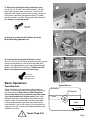
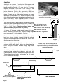
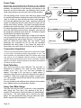
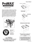
Contents of Box
model number
RT100
Owner's Manual
Congratulations and thank you for buying our router
table! If you have any questions, please give us a
call. This manual will assist you during the assembly
of your router table. However, this manual is not
intended as an instructional manual for router table
usage. Please consult the widely available books,
magazines, and classes on router table techniques.
H
NC D
TO
OLS
routertop
fence
phenolic ProPlate, standard 2" bit hole (router insert plate)
miter track
12
2
1
2
14
12
10
2
1
1
2
4
Router Table Hardware
1/4-20 x 2" round head bolts for cabinet and top
1/4-20 x 3/4" phil. flat head ms for insert plate
1/4-20 x 1" phil. flat head ms for miter track
1/4-20 x 2" phil. flat head ms for miter track
1/4-20" cross dowels for cabinet and top
7 x 40 mm insert plate leveling screws
1/4-28 x 1/2" set screws for miter track
Euro hinges and mounting plates with screws
door stop with (1) #7 x3/4" screw
nylon handle with (2) #8 x 1-1/8" screws
aluminum trim strips for routertop
#6 x 1/2" screws for trim strips
1
1
1
1
1
Cabinet Panels
left side panel
back panel with cord cut-out
right side panel
base panel
door panel
2
2
2
2
6
4
1
1
2
2
2
Fence Hardware/Accessories
3/8-16 x 3" carriage bolts for fence mounting
3/8" nylon handle spacer washers
2-1/2" t-bar knobs for fence mounting
1/4-20 x 3/4" hex bolts for bit guard mounting
1-1/8-1/4" knobs for sub-fence and guard mounting
1/4" x 40mm shoulder bolts for subfence mounting
dual position bit guard
dust port (slides into fence)
MDF subfences
aluminum knob spacers
aluminum jointer bars (pair)
Tools Required
OG
BE
Thank you for choosing Bench Dog!
1
1
1
1
Bench Dog, Inc.
3310 5th St. NE
Suite 100
Minneapolis, MN 55418
612.782.8205 main
612.788.2518 fax
800.786.8902 toll free
[email protected]
www.benchdog.com
Assembly
Symbols
4 mm Allen wrench (supplied)
!
Warning
1/8" Allen wrench (supplied)
I
Important
screwdriver and power drill
Mounting Router
drill bit (sized to your router)
countersink 82 degree
drill press (recommended)
QUESTIONS?
1-800-786-8902
Be sure to check out our web site for all the
latest and greatest accessories and tools.
www.benchdog.com
Read and understand the entire contents
of this manual before attempting assembly
or operation of this tool! Inspect contents
for shipping damage and shortages. Report
problems directly to Bench Dog, Inc.
2002 Bench Dog, Inc.
82-0007-01 1102
General Conditions and Limited Two Year Warranty
We make every effort to assure that our products meet quality and durability standards, and warrant to the original retail
purchaser that this product is free from defects in materials and workmanship for two years. Remedy shall be limited to
Bench Dog's choice of repair, replacement or refund. This warranty does not provide remedy for consequential economic
loss.
This is a limited two year warranty. It requires the purchaser to contact Bench Dog in writing within 30 days of discovering
the defect. Warranty does not apply to defects due directly or indirectly to misuse, abuse, negligence or accidents, repairs
or alterations, or due to lack of maintenance. It excludes components and parts not manufactured by Bench Dog, defects
caused by failure to provide a suitable installation environment, and damage caused by use for purposes other than those
for which the product was designed.
Bench Dog, Inc. reserves the right to make product changes without notice and without obligation to make these changes
on products previously sold.
Important Safety Points
Before operating your router table please read this manual thoroughly. Safety and use tips are contained in the
manual. This page is not the sole source of safety information. Retain the manual for future reference. Refer to
your router owner's manual for safety instructions regarding use of that tool. This manual is not an instruction book on
how to do woodworking with a power tool. We encourage all woodworkers to continually seek improvement in their
woodworking skills, regardless of their craftsmanship or years of experience. The router table, fence and accessories
must only be used for their intended purpose: woodworking via normal routing operations. “Normal operations” means
basic shaping of wood in conditions where grounded electricity, sharp tools, dust, and rapidly spinning parts can be
used or encountered safely. The following instructions elaborate on this concept.
1.
2.
3.
4.
5.
6.
7.
8.
9.
10.
11.
12.
13.
14.
15.
Do not use your router table as a step or seat.
The top and cabinet must be properly secured, and be level before use. Inspect your table and base for
damage and levelness prior to each use.
Keep work area clean, dry and well lit.
The hardware affixing the insert to the routertop must be installed for safe use. Tighten insert hold-down
screws before each use.
Safe operation requires a router table fence, bit guard, dust collection system, starting pin or fulcrum, and
speed reducer for large diameter bits. We recommend reducing router speed for 1" or larger diameter bits.
Consult your bit manufacturer for the exact speed.
Use the right tool for the job. Do not force a tool or attachment to do a job for which it was not designed.
Secure your work with a featherboard, clamps, or a vice when appropriate. The use of inappropriate
accessories may cause injury.
Wear safety glasses, dust mask, face shield and ear protection. This is not an exhaustive list. Every-day
eye glasses do not substitute for safety glasses.
Do not wear gloves or jewelry while using a power tool and ProTop.
Maintain your equipment and its accessories in good working condition. Look for wear, poor alignment of
moving parts, binding of moving parts, breakage, poor mounting, or other conditions that may affect
operation and safety. Repair or replace any damaged parts.
Disconnect the power before moving, adjusting, or repairing parts, or otherwise maintaining your router table
and any accessories you may be using.
Keep children, pets, and those who may disregard safety away from work area, cords, sockets and tools.
Wear snug fitting clothes and keep long hair back to avoid catching in moving parts.
Do not overreach. Maintain balanced footing and stance.
Stay alert. Use common sense.
In any correspondence with Bench Dog, Inc., please refer to the date and place of purchase. You may reach us at
Bench Dog, Inc. 3310 5th St.. NE, Suite 100, Mpls., MN 55413 USA, (612) 782-8205 or 1-800-786-8902. On the
internet, you may reach us at www.benchdog.com.
Page 2
Assembly Instructions
1
1. Attach the Euro hinges to the door as shown.
Press the hinge cups into their bores. Turn the integral hinge
cams to tighten.
(cabinet inside)
cup holes for hinges
Door
door handle holes
2. Attach the hinge mounting plates to the left side cabinet
panel.
Note the orientation in the photo. The hinge resembles the letter
"t". Locate the top of the "t" nearest the front edge of the side
panel as shown in the photo. Make sure the spring loaded
release lever faces the back edge of the cabinet.
Spring loaded
release lever
Left Side (top)
(cabinet inside)
Front Edge
of Cabinet
2
Top of "T"
mounting
plate.
holes for hinge
mounting plates
cross dowel holes
Front edge
of cabinet
3. Attach the plastic door stop to the right side cabinet panel.
Use the small #7 x 3/4" silver colored wood screw.
Right Side (top)
Door stop detail
3
(cabinet inside)
plastic door
stop hole
4. Attach left and right side panels to the back panel.
Do not install the panels upside down. Position the cord cut-out
to the bottom right. Use the 1/4-20 x 2" round head bolts and
cross dowels, and the supplied 4mm wrench to tighten the bolts.
The cross dowels may fit tightly into their holes. Tap them in with
a hammer if necessary. The drawing below shows how these
strong but simple fasteners fit together.
1/4-20"
cross dowel
4
Bolt
Panel
Cross Dowel
1/4-20 x 2"
round head bolt
Panel
Page 3
5. Attach the cabinet base panel.
Flip the cabinet over, as shown. Use the same 1/4" round head
bolts and cross dowels as above. When done, flip the unit right
side up. Note: the bottom side of the cabinet base panel has
counter bored holes to accept the bolt heads.
5
6. Install the (12) leveling screws (for the insert plate).
Place the routertop face down, as shown. Use a power drill, and
drive the screws in until they barely come through the other side.
You will fine adjust them in step 11. Some cracking of the
laminate's color layer may occur, but this will not affect the
product's performance.
6
!
7 x 40mm
leveling
screw
Drive the leveling screws
into the (12) small holes. Be
careful not to drive a leveling
screw into the two larger
insert holes!
7. Attach the (2) aluminum trim strips to the routertop.
Use the (4) small #6 x 1/2 screws. Use a phillips screwdriver and
install by hand. Be careful not to over tighten the screws. Do not
use a power drill in this step! The trim strips are purely decorative.
Position the trim strip as shown, and drive the screws into the
bottom of the routertop.
!
Drive the screws into the
bottom of the routertop, not
into the side of the routertop!
7
8
8 Attach the routertop to the cabinet.
Use (3) of the same 1/4" round head bolts and cross dowels
as used earlier. Attach the routertop to the cabinet sides and
back panel.
Page 4
9. Attach the miter track to the routertop.
First install (2) 1/4" cross dowels in the cabinet side panels. The
center miter track screw attaches to a factory installed insert.
Use the (2) 1/4-20 x 2" phil. flat head machine screws in the
outside track holes. The center track hole uses the 1/4-20 x 1"
phil. flat head machine screw.
9
1/4-20 x 1"
phil. flat head
machine screw
1/4-20 x 2"
phil. flat head
machine screw
10. Adjust the miter gauge track to fit your miter gauge.
Begin this step by first test fitting your miter gauge for fit. If it fits
too tightly, lightly squeeze the gib towards the front edge of the
track to open it wider. Protect the edges with a cloth. Next,
install the (12) 1/4-28 x 1/2" set screws into the track. The screws
tighten the miter track by deflecting the gib. Tighten all the
screws uniformly and gradually until desired fit is achieved. Use
the supplied 1/8" Allen wrench. The slot is designed to fit your
standard 3/4 x 3/8" miter gauge bars. Use the "t" slot to mount
accessories. (It's the smaller slot, and accepts 1/4" hex bolts).
Wax the track and bar to prevent undue wear!
10
I
Note: you may have extra set screws.
11
11. Adjust the leveling screws until the insert is flush.
First, remove the protective paper from your acrylic router insert
plate, and drop it into the routertop opening. Here, the user is
checking flushness with his right hand while adjusting the
leveling screws with his left. Fine adjust the six screws at the
four corners of the insert opening first. Then, adjust the
remaining screws.
I
Important! In step 18 you will mount your router to the insert
plate. After that, you may again need to fine adjust the
plate's flushness.
12
12. Attach the nylon door handle.
Use the (2) #8 x 1-1/8" screws, as shown.
#8 x1-1/8"
screw
Page 5
13. Clip-on the door and adjust the hinges if necessary.
If your hinges do need adjustment, see below. Please, take your
time to figure out how the hinges clip on. You'll get the hang of it
soon enough! Our "Euro" style hinges are strong, self-closing, and
clip on and off. Note, removing the door makes clamping to the
leading edge of the routertop easier. However, keep the door
installed to cut down on dust and router noise.
Lateral
Adjustment
Screw
Frontal
Adjustment
Screw
!
13
Vertical
Adjustment
Screws
Don't force the hinges onto
the mounting plates!
14. Install the dust port.
Pull the port along the two grooves extruded into the fence until it
snaps into place in the center bit opening area. The port will fit
tightly.
15. Install the (2) MDF subfences onto the fence.
Use the (4) 1/4-20 x 40mm shoulder bolts and t-knobs. The
subfences have no left/right or up/down designation. The bolts are
designed to fit snugly into the subfences to prevent the heads from
spinning. Light finger pressure on the head of the bolt may be
necessary. The bolt heads must recess into the subfence counter
bores.
14
15
1/4-20 x 40mm
shoulder bolt
16. Attach the fence to the routertop.
Use the (2) 3/8-16 x 3" carriage bolts, (2) aluminum knob spacers,
(2) 3/8" nylon handle spacer washers, and (2) large t-knobs. The
bolts enter from inside the cabinet. To adjust the fence, simply
loosen both fence knobs until the fence slides smoothly. The
fence does not have to remain parallel to the front edge of the
router table unless you use it in conjunction with a miter gauge.
Loosening just one knob and pivoting the fence is an effective way
to attain fine adjustments.
fence
clamp handle
handle spacer
3/8" nylon handle
spacer washer
routertop
Page 6
3/8-16 x 3" carriage bolt
16
17. Attach the dual position bit guard to the fence.
Use the (2) 1/4-20 x 3/4" hex bolts and knobs. The bolt
heads slide into the t-slots on the fence. These t-slots
capture the bolt heads to prevent their turning. The guard
in the photo is positioned for general routing. The other
end of the guard is used for jointing and smaller diameter
bits. Always use your bit guard!
17
1/4 x 3/4"
hex bolt
18
18. Mount your router to the ProPlate. Go to the
Router Mounting Appendix now.
19. Install the (2) insert plate hold-down screws.
The (2) 1/4-20 x 3/4" phil. flat head machine screws prevent
side to side movement, as well as keep the plate firmly
seated. Over tightening the screws may deform the plate.
Readjust the plate flush if necessary. Tighten the holddown screws before every use, if necessary!
19
1/4 x 3/4"
phil. flat head
machine screw
Basic Operations
*Router not included.
Typical Set-up
Feed Direction
Always feed your stock against the cutter rotation, as
shown. If you feed your stock with the cutter rotation you
are climb cutting. Climb cutting is VERY dangerous
because the router bit can grab the stock from under
your hands and throw it at great speed. Even small
diameter router bits can overpower your ability to hold
onto the stock. Do not attempt to use the router table
until you understand that you feed your stock into the
cutter rotation. If you're still unclear, ask your retailer for
help, give us a call, or study router table techniques with
a book or in a class.
!
Routertop
Bit Rotation
Fence
Stock
Feed Direction!
Never Climb Cut!
Page 7
Jointing
Jointing is the process of making two flat, square, and
straight mating edges. Jointing is usually done before two
boards are glued together. It is also used to "fit" pieces
together, as well as to trim stock to size. Jointing on the
routertop is not designed to replace a free standing power
jointer. However, jointing with your router table has
advantages over other methods. First, small and short
pieces of wood can be safely jointed because the throat
opening is also small: about 1/2". Second, the quality of the
cut is better than the typical jointer because the router bit
spins much faster. This is especially useful on woods
prone to tear-out, like curly or burled woods.
In this photo, the user is sliding the
second bar into position.
Your fence has built-in jointing slots to accept the (2) small
aluminum jointer bars shipped with your fence. Installed in Here, the jointer bars are
pairs, these bars "shim out" the out feed subfence either mounted in slots 2 and 4.
1/32" or 5/64" (2mm). The instructions below are
Slots 1 and 3 = 5/64" (2mm Cut)
specific to setting up your fence for jointing.
1
2
Slots 2 and 4 = 1/32" Cut
1. Install a 1/2" diameter straight or spiral up-cut bit in your
router. Use only 1/2" shank bits. The bit's cutting length Note the small "v" grooves.
must not exceed 1". Set the height to 1" or less.
4
2. Loosen the outfeed subfence mounting knobs and slide
both bars (always installed in pairs!) under the outfeed
subfence in either the 2nd and 4th slots, or the 1st and 3rd.
See the upper right illustration.
3. Use a straight edge to adjust the router bit and outfeed
subfence to the same plane. Tighten the fence clamping
knobs. Readjust if needed. Remove straight edge when
done.
4. Slide both sub fences towards the bit to decrease the
amount of gap between the subfences and router bit.
Confirm that the subfences are not touching the router bit.
Tighten the subfence knobs, and position the bit guard.
Plug-in your router and begin.
3
outfeed
subfence
If board "snipe" occurs, realign the out
feed subfence to the router bit. Don't be
surprised if it takes you one or two tries to
master this operation.
snipe
(Bit guard not shown for clarity, only!)
fence (top view)
jointer bars
outfeed subfence
router
bit
infeed subfence
straight edge - remove before jointing!!!
Stock (wood)
!
Always use a push
stick or pad when jointing!
Page 8
Outfeed subfence and
router bit are set to the
same plane!
Feed Direction
Adjusting the Subfences
The (2) MDF (medium density fiberboard) subfences are
designed to slide along the fence approximately 2". This
results in a router bit opening from 0" to 4". Adjusting
the subfences into the routerbit profile produces "zero
clearance". Essentially, zero clearance eliminates the
gap between your fence and the router bit, the major
reason your stock gets sucked into the fence just before
the router bit. Moreover, less chip-out occurs because
the subfence supports the fibers of the wood stock you
are cutting.
A. "Close" Setting
In many instances, adjusting the subfences close to the
router bit is all that is necessary, and accomplishes
about the same thing as a true zero clearance setting.
Before the router is turned on, and after the fence and
router bit height are properly adjusted, simply slide the
subfences towards the bit to reduce the gap. After
setting the subfences close to the bit, make absolutely
sure the router bit can freely move without running
into the subfences before turning on the router!
B. "Zero Clearance" Setting
If a true zero clearance setting is desired, follow the
instructions below.
1. Set the bit height and fence where you need
them. Confirm that the bit, router, insert holddown screws and fence are properly set and secure.
along the same plane. Final router bit height must
be set! At this point the subfences must not touch the
router bit.
Router Bit Guide Bearing
Outfeed Subfence
Infeed Subfence
Bit
Outfeed Subfence
In this drawing, above, the
infeed subfence is not set to
zero clearance.
Infeed Subfence
Bit
In this drawing, above, the
infeed subfence is set to
zero clearance.
Important Notes:
The outfeed subfence is almost never set to zero
clearance because a "close" setting usually works
just fine. Setting the outfeed subfence to zero
2. Install the bit guard.
clearance requires great care because the router bit
can cause a portion of the outfeed subfence to chip3. Connect your vacuum to the dust port.
out or break. Therefore, if you must use zero
4. Start the router. From the back of the
clearance, slide the subfence very slowly into the
fence, slightly loosen the subfence knobs until the
bit to minimize these affects. Otherwise, just set the
subfence can move. Carefully slide the infeed subfence outfeed subfence close to the bit.
towards the router bit. Hold onto the subfence
knob as shown in the photo above. Never
push the subfence with your hands on the face of it.
5. When the infeed subfence has stopped
on the routerbit's guide bearing, fully tighten the
subfence knobs and proceed with your operation.
If your bit has no guide bearing, (e.g., vertical
raised panel bits), slide the subfence half-way
into the bit. Tighten the knobs. Zero clearance
has been achieved.
Flip the subfences when you change bit profiles or
heights. Purchase new subfences when all ends are
wasted, and when the ends cannot be trimmed to
provide a fresh edge.
MDF works perfectly as a subfence because it is
softer than most woods, and is much kinder on
delicate profiles. Razor edges remain after
producing lock miter and other profiles.
When adjusting the fence, ensure that no part of the
aluminum will be in the zone of contact with the
router bit.
Page 9
Fence Traps
Fence traps occur whenever the work piece is fully "trapped"
between the router bit and the fence. Fence traps pose two real
problems: the possibility of climb feeding, and exposure to the
router bit. As you've read earlier, you absolutely want to avoid
climb cutting, because you may lose control of the operation.
The top drawing shows a classic trap. What may appear to be
the normal feed direction (working from right to left) will instead
result in a climb cut. And, because the work is also trapped, it
will surely be grabbed from your hands, and thrown with great
speed. If instead you feed the stock from left to right, you will
not be climb cutting. However, this doesn't overcome the other
problems that come with a trap. First, it will be difficult to keep
the stock tight against the fence, as the bit's rotation will tend to
thrust the stock away from the fence. Secondly, your body will
be dangerously exposed to the router bit. The factory bit guard
will not protect you against flying stock.
The next drawing is not a classic trap, as long as the router bit
cuts only partially into the stock! In this cut, the forces will tend
to grab and push the stock toward the fence. This is good. The
fence will control the force better than your hands. Typical
dado-type cuts resemble this set up, and are commonly
performed with router tables. If you widen the dado with a
second pass, be careful not to set a classic trap or a climb cut.
Fence
Stock
NO!
b it
r o t a ti o n
Classic Trap!
Fence
b it
Stock
r o t a ti o n
Not a trap.
Temperature Regulation
There are several preventative measures to reduce the chance
of your router overheating during long periods of use. Two
basic methods are to periodically open the cabinet door during
use, and to use an adequate vaccuum source in conjunction
with the fence mounted dust port to insure circulation. Another
option is to install a second dustport to the cabinet for added air
ciculation and dust control.
Dust Collection
Your fence has built-in dust collection. The dust port is
designed to fit standard 2-1/2" shop vac hose (fittings are
actually 2-1/4" O.D.). For 1-1/4" vac hose, purchase an
adapter. (The larger 2-1/2" vac hose is a better choice.) If
necessary, wrap the end of your hose fitting with duct tape for
a tighter fit. Three inch or larger hose requires a reducer to 21/2". Then, connect the port to the reducer with a short section
of 2-1/2" vac hose.
You may choose to add additional dust collection at the cabinet
level. Supplies for this are not provided, however.
*Hose not included.
Using Your Miter Gauge
The miter track has two slots: a t-slot and a t-bar compatible
miter gauge slot. The t-slot is the narrower of the two. It
accepts 1/4" hex bolts for attaching Feather-Loc featherboards
and the like. The miter gauge slot is used for your miter
gauge. The miter gauge that came with your table saw works
well as long at it has a standard 3/4" x 3/8" bar.
Page 10
Incorrect feed direction!
*Miter gauge not included.
Correct feed direction!
Bench Dog Accessories
ProLift Ni and ProLift Al top adjust router systems
ProLift allows you to change your bits above the table without removing the
motor or lift - simply use your factory wrenches! ProLift is available in either cast
iron or aluminum models and features three bit opening sizes, cooling fins, zeroadjustment from any bit height, and four threaded starting pin locations. Expand
ProLift's versatility with one of several accessories. ProLift accommodates fixed
base routers only. ProLift Ni accepts 4.2" diameter motors and less - ProLift Al
3.5" diameter and less. p/n PL1001, PL1002. Patents pending.
ProLift Ni shown,
Router not included.
p/n PL1002
Panel-Loc panel cutting handguard / hold-down
Panel-Loc is the first combo hand guard and panel hold down for routing
panels. The unique aluminum shape and UHMW contact strip places
pressure on exactly the right location. It also protects your hands,
alleviates chatter, reduces fatigue, and improves results. Includes a
special mounting t-track for all fences. p/n PL400. Patents pending
Panel-Loc shown on
ProTop Complete.
p/n PL400
AC C E S S O RY
Feather-Loc feather boards
Feather-Loc is our four-in-one featherboard with a built-in tension
setup feather. On our router tables, Feather-Locs are featherboards,
fence stops, table stops, and a starting pin and fulcrum. Feather-Locs
mount directly to your table's t-slots p/n FL200. For table saws, use p/n
FL100, which includes one featherboard and one 3/4" x 3/8" miter slot
2 pair Feather-Loc
adapter. Patents pending.
shown on a ProTop
complete. p/n FL200
AC C E S S O RY
ProPlate insert plates
ProPlates are the perfect way to change your router bit hole size. We offer
plates with hole sizes from zero to 3.6". ProPlates come in acrylic, phenolic,
and aluminum in both predrilled and undrilled styles. ProPlate aluminum
features removable insert rings, four starting pin locations, and a supporting
line of accessories. No matter what model router you own, Bench Dog has
you covered.
Undrilled ProPlate
aluminum shown.
p/n M1001
AC C E S S O RY
Fence Riser Option
A fence riser option is available for your fence. The function of the riser is
to add height to your fence. This gives your work more support during
vertical cutting operations. Cutting vertical raised panels is a common
task made easier with the riser option. The cutting of dovetails and
tenons are other examples. In this photo the user is attaching the MDF
fence to the riser brackets. p/n FR400/100.
H
NC D
TO
OG
BE
AC C E S S O RY
OLS
Please contact us if you have any questions (1-800-786-8902).
Be sure to check out our web site for all the latest accessories and tools.
www.benchdog.com
Page 11