1
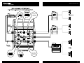
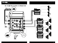
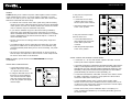
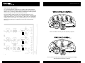
XM6 OWNER’S MANUAL
877 COUSTIC
WWW.COUSTIC.COM
WWW.COUSTIC.COM
WELCOME
…to the Coustic Car Audio world of hard-hitting, high-quality mobile audio
products. The new Coustic XM6 electronic crossover utilize the industry's
most advanced sound engineering and manufacturing processes to offer the
highest quality electronic crossovers available on the market today.
Besides its sleek, contoured design, the new XM6 offers the latest complementary audio features. This booklet offers you a guided tour of all these
exciting benefits. For optimal sonic reproduction, please follow the installation
suggestions and recommendations as closely as possible. The time you
spend will prove to be worthwhile when you sit back and enjoy the high
fidelity music!
Whatever your needs for your ultimate car audio system, look to Coustic
Car Audio – we have the fullest range of car audio components to meet the
most critical demands.
No part of this publication may be reproduced, stored in a retrieval system,
or transmitted in any form or by any means, electronically, mechanically, or
otherwise, without the prior written permission of Coustic or Mitek
Corporation.
Please take a moment to register your purchase on line at www.coustic.com.
Please also record the serial number of your crossover in the space provided
below and keep this manual for future reference, as well as your sales
receipt as proof of ownership. (The serial number of your crossover is marked
on the bottom of its metal chassis.)
Serial Number:
Date of Purchase:
3
WWW.COUSTIC.COM
FEATURES
ASYMMETRICAL ELECTRONIC CROSSOVER DESIGN
FREQUENCY MULTIPLIER
The advantage of asymmetrical crossovers over “symmetrical” crossovers is
the ability of the former to eliminate undesirable peaks and dips in frequency
response caused by resonant frequencies present in all enclosed space. Since
the crossover points can overlap or underlap the resonant frequencies (i.e.
"asymmetrically"), Coustic XM6 series allows you to create an acoustically
flat and smooth frequency response environment.
The frequency multiplier switch found on channel “A” of the XM6 is used to
multiply the selected high pass crossover points by 20 times.
DEFEATABLE BAND PASS SWITCH
This switch changes the XM6 “B” channel output configuration from a high
pass output to a band pass output.
LINE LEVEL INPUTS
The XM6 crossover features pre-amp inputs for use with source units that
have RCA or line level outputs. An independent set of line level inputs are
provided on the XM6 for 2-, 4- or 6-channel connections.
BASS SHAPER (BOOST AND EQ)
PARALLEL INPUT SWITCH
BASS-DRIVE™ (REMOTE SUB GAIN CONTROL PORT)
This feature allows all XM6 outputs to be driven with either a 2-, 4- or
6-channel input configuration. An adapter is not needed to split the source
signal to the “A”, “B”, and sub inputs when the XM6 is used with a source
unit that only has a single or dual pair of RCA or line level outputs.
The optimum subwoofer output level changes with road noise that varies
according to vehicle speed, wind speed and road surfaces. With our exclusive
Bass-Drive™, the subwoofer output level can be adjusted via the model R S
remote control to minimize the undesirable effect of fluctuating road noise.
DUAL STEREO AND SINGLE MONO LINE LEVEL OUTPUTS
PULSE-WIDTH MODULATED (PWM) SWITCHING POWER SUPPLY
The XM6 features three line level outputs each sending independent audio
signals to designated amplifiers. Channel “A” and “B” on the XM6 both
have stereo outputs while the sub channel output is mono.
The Coustic XM6 features a Pulse-width modulated (PWM) switching power
supply. The PWM is used to ensure consistent output performance and to
eliminate unwanted noise caused by voltage fluctuation.
INDEPENDENT VARIABLE LEVEL CONTROLS
PHASE CONTROL SWITCH
The adjustment of output levels allows precise control of the signals going to
its respective amplifier. Channels “A” and “B” on the XM6 feature independent left and right output level controls allowing for accurate stereo balance
within the vehicle. Since the sub channel output is mono, a single adjustable
output level control is used to ensure a smooth low frequency response.
Depending on their placement, an acoustical delay may exist between the
time the subwoofer, midrange and tweeter signals is heard. With the XM6’s
Phase Inverter, you can compensate for this time delay.
CONTINUOUSLY VARIABLE CROSSOVERS POINTS
2) Shifting the subwoofer output signals 180 degrees out of phase relative to
channels “A” and “B” output signals.
This feature allows for individual high pass, band pass and low pass
crossover settings that can be selected within a range of frequencies to
ensure optimum system performance. The band pass setting is only operable
when the band pass mode is selected. (See Defeatable Band Pass Switch)
This feature enhances the bass performance of the sound system by providing
up to 18dB of boost from a selectable frequency range of 40Hz to 100Hz.
1) Shifting the right output signals on channels “A” and/or “B” 180 degrees
out of phase relative to their left output signals.
5
WWW.COUSTIC.COM
XM6: TERMINALS
1
2
3
4
5
XM6 INPUT PANEL
7
8
9
10
1
Power Input Terminal (B+) – Connects to the positive terminal of your
vehicle battery or other constant +12V source
2
Ground Input Terminal (GND) – Connects to the vehicle’s chassis
ground
3
Remote Turn-on Input Terminal (REMOTE) – Connects to the remote
control wire or antenna lead of the source unit for remote ON/OFF
4
“A” Line Level Inputs – Connects to the front channel RCA output of the
source unit
5
“B” Line Level Inputs – Connects to the rear channel RCA outputs of the
source unit
6
Subwoofer Line Level Inputs – Connects to the subwoofer channel
RCA outputs of the source unit
7
Bass Drive™ Remote Sub Gain Control Port – Connection for optional
R S remote to control subwoofer output levels
8
Subwoofer Line Outputs – Connects to the dedicated subwoofer amplifier left/right inputs
9
“B” Channel Line Outputs – Depending on the “B” channels’
configuration, the crossover’s “B” channel outputs connect to the
dedicated Rear/high pass or band pass frequency amplifier inputs
6
10 “A” Channel Line Output – Depending on the “A” channels’
configuration, the crossover’s “A” channel outputs connect to the
dedicated front or high frequency amplifier inputs
XM6 OUTPUT PANEL
7
WWW.COUSTIC.COM
XM6: CONTROLS & INDICATORS
11 Parallel Input Switches – “IN”: Each appropriate switch must be set
to the “IN” position when the source unit does not supply rear or
subwoofer channel outputs. “OUT”: If the source unit has independent
front, rear and/or sub channel outputs, set each switch to the “OUT”
position
12 High-Pass Frequency Selectors – For selection of high-pass crossover
frequency between 40Hz and 400Hz, 18dB/Octave
13 Frequency Multiplier – To change selected high-pass crossover
frequencies from 40Hz - 400Hz, to 800Hz - 8000Hz, 18dB/Octave
14 Band Pass Switch – Positioning this switch to the “IN” position reconfigures the “B” channel from a high pass output to a band pass output.
When the “IN” position is selected, the band pass frequency selector is
engaged.
21
13
12
19
16 Subwoofer Frequency Selector – For selection of the low-pass crossover
frequency between 40Hz and 200Hz, 36dB/Octave
15
11
21
12
11
23
16
17
18
17 Bass Shaper Frequency Selector – For selection of low frequency
equalization point between 40Hz - 100Hz.
18 Bass Shaper Boost Level Control – For adjusting the Bass Shapers
selected equalization frequency level with a maximum boost of 18dB
19
14
15 Band Pass Frequency Selector – For selection of the top crossover point
of the band-pass frequency range between 300Hz and 3kHz,
18dB/Octave. (The high pass frequency selector must be used to
select the bottom crossover point for the band-pass frequency range.)
The full band pass frequency range is 40Hz to 3kHz, 18dB/Octave.
20
22
19 Phase Control Switch – Positioning the switch to the “180”
position shifts the right output signals on channels “A” and/or “B”
180 degrees out of phase relative to their left output signals
20 Sub Phase Control Switch – Positioning the switch to the “180”
position shifts the subwoofer output signals 180 degrees out of phase
relative to channels “A” and “B” output signals
21 Independent Output Level Controls – Independent left and right output
signal level adjustments can be made for accurate stereo balance and
imaging
XM6 CONTROL PANEL
22 Subwoofer Output Level Control – For adjusting the low pass output
signal level
23 Power Indicator – This indicator lights up when the internal switching
power supply is activated and the unit is operational
9
WWW.COUSTIC.COM
INSTALLATION
FOR SAFETY, DISCONNECT THE BATTERY GROUND BEFORE INSTALLATION.
Caution: Please follow all the installation recommendations and instructions
in this manual. Installing and/or using the XM6 electronic crossover
in methods other than those outlined herein may reduce the performance
capability of the crossovers. Any such installation or usage may render the
product warranty void.
PREPARATION
Before wiring and connecting the XM6, please read the entire manual.
Mark down the accessories, tools required and important points as you go
through this manual. Have all the necessary accessories, hardware and tools
on hand. The following basic tools are required:
• Electric hand drill with assorted bits
Note: Please check with your vehicle’s manual to see if special tools are
necessary for working on your particular vehicle.
Check and make sure the vehicle’s main battery and/or auxiliary battery, if
any, is/are in good working condition and has sufficient capacity to run the
electrical components of the vehicle plus the complete audio system.
The XM6 crossover is designed for use in 12 Volt NEGATIVE GROUND
electrical system ONLY. Installing the units in a vehicle with positive ground
electrical system could result in serious damage to the electronic crossover,
other audio components and/or the vehicle’s electrical components. If your
vehicle happens to run on a positive ground electrical system, please consult
your Coustic dealer for specific instructions on installation.
LOCATION
• Select a mounting location that is easily and conveniently accessible,
e.g. inside the trunk.
• Screwdrivers (Phillips and flat head)
• To avoid damage to the unit, keep the crossovers away from any heat
source (such as the engine or any heat-generating ducts).
• Pliers
• Leave at least 6" clearance above the unit to allow easy adjustment.
• Wire cutters
• Wire strippers
MOUNTING
• Sharp knife
• Place the XM6 crossover at the desired location and use it as
a template to determine the exact position of the mounting holes.
• Crimping tool
• Mark the mounting holes with a felt pen, and put the crossover aside.
• Electrical tape or heat shrink tube for professional finish
• If the mounting surface is carpeted, cut out small circles of the carpet
and padding around the four mounting holes to expose the metal
underneath.
• Soldering Iron (propane torch type) with solder
• Nylon tie wraps
• Volt/Ohm meter
• Use a center punch to ensure drilling the exact position for the screws.
Drill four (4) 1⁄8” pilot holes. DO NOT BEGIN DRILLING UNTIL YOU
HAVE PUT THE CROSSOVER ASIDE. USING THE CROSSOVER AS A
DRILLING GUIDE MAY CAUSE IRREPARABLE DAMAGE TO THE UNIT.
• Mount the XM6 crossover with the Phillips head sheet metal screws
and steel washers provided. (It is best not to tighten the screws to the
maximum at this stage, since you might want to change the position at
a later stage.)
11
WWW.COUSTIC.COM
See Page 20
XM6 Phase
Adjustment
See Page 20
XM6 Phase
Adjustment
13
WWW.COUSTIC.COM
See Page 20
XM6 Phase
Adjustment
15
WWW.COUSTIC.COM
WIRING
Caution: Routing audio cables and power cables together would invariably
cause radiated engine noise in your audio system. If possible, run audio
cables on one side of your car and power cables on the other. Never route
these wires underneath the vehicle body.
• It is best to route all wires of the audio system along with the existing
electrical wires of the vehicle through this would call for the dismounting
of kick panels, door sills, etc. Where possible, the cleanest and safest
route is under the carpet or behind the side panels.
• If you need to dismantle any part of the vehicle during installation,
make notes of the dismantling process to ensure that you would be
able to reassemble those parts afterwards. All the hardware, for example,
screws, dismantled from the vehicle should be kept in a container to
make reassembly easier.
• Run the various wires accordingly while avoiding sharp edges and
door jams.
• Grommets should be used to protect the wires when they are routed
through bare metal holes. For best protection, we recommend using
automotive flexible plastic tubing and for ease of handling, use plastic
tie-wraps.
if using the rear outputs from
the source unit
• Connect the rear line level
outputs of the source unit to
the “B” inputs of the crossover.
• Slide the parallel input switch
to the “OUT” position.
if using the subwoofer outputs
from the source unit
• Connect the subwoofer line
level outputs of the source unit
to the “SUB” inputs of the
crossover.
• Slide the parallel input switch
to the “OUT” position.
• All wires and cables should be “stress relieved” at various points on
both the input and output side of the crossovers. Cable clamps should
be used to reduce stress on the terminals.
Note: The battery ground should remain DISCONNECTED at all stages
of installation.
AUDIO INPUT CONNECTIONS
• Connect the front line level
outputs of the source unit to the
“A” inputs of the crossover.
• If using the XM6 with source unit
that does not have additional
rear and sub line level outputs,
slide each parallel input switch
to the “IN” position and skip the
next two steps.
AUDIO OUTPUT AND POWER CONNECTIONS
• Connect the “A”, “B” and sub channel outputs of the XM6 crossover
to the inputs of their respective amplifiers.
• Connect the crossovers’ B+ terminals to the positive terminal of the vehicle’s
battery. Cut the supplied fuse loop (so there are now two separate wires
that attach to each end of the fuse holder). Install the fuse holder 18" from
the battery on the power wire that runs through firewall or sheet metal to
protect the battery, the vehicle and more importantly, you.
• Connect the GND terminal of the XM6 crossover to the vehicle chassis.
For better conductivity, if necessary, scrape paint off of the chassis to
reveal bare metal at the contact point.
• Connect the REM terminal of the crossover to the remote output
terminal of the source unit to establish crossover remote power on/off
via the source unit. If the source unit does not provide a remote output,
connect to its power antenna terminal.
• Double check all the previous installation steps. If everything is in
order, complete the installation by reconnecting the battery ground to
the vehicle chassis.
17
WWW.COUSTIC.COM
ADJUSTMENTS
CROSSOVER FREQUENCY ADJUSTMENT
OUTPUT LEVEL ADJUSTMENT
To avoid over-crowding the control panel, only four frequencies are shown
on each frequency selector. In reality you can choose any of the frequencies
between the lowest and the highest setting marked on the selectors.
As in the case of crossover frequency adjustment, when making the output
level adjustment it is best to use compact discs or cassette tapes with
greater dynamic range.
• When setting the crossover frequencies, it is best to use compact discs
or cassette tapes with greater dynamic range
• Center the tone, balance and fader controls of the source unit (leaving
the other controls at their previous positions).
• Center the tone, balance and fader controls of the source unit (leaving
the other controls at their previous positions)
• Set the volume of the source unit to approximately 2⁄3 of its maximum
output.
• Set the volume of the source unit to approximately 2⁄3 of its maximum
output
• Starting from their respective preset levels, adjust one output level at
a time. With each of the level controls, turn the level up or down until
distortion develops, then retrace the path until distortion disappears.
Additional adjustment may be required for even stereo balance.
CHANNEL “A” CROSSOVER FREQUENCY SETTING:
Choose the appropriate frequency range for your speakers by selecting
either the x1 or x20 setting on the frequency multiplier switch. Adjust the
fader of the source unit to increase the volume level on channel “A”.
Starting from the preset frequency, adjust frequency control downward or
upward until you get your desired sound quality.
CHANNEL “B” CROSSOVER FREQUENCY SETTING:
Depending on your systems configuration, channel “B” may be used in either
a high pass or band pass mode. By selecting the “IN” position on the band
pass switch, the band pass frequency control is engaged allowing for top
crossover frequency adjustment. Adjust the fader of the source unit to
increase the volume level on channel “B”. Just like setting the “A” channels,
starting from their respective preset frequencies, gradually adjust the high
pass and/or the band pass frequencies downward or upward until you get
your desired sound quality.
• Optimum output levels vary with the program source (radio, tape or
CD). If the optimum output levels for radio differ considerable from
those for tape/CD, locate the median levels that are best for both
program sources. (Before making output level adjustment for radio,
first locate a FM station with strong radio signals.)
• The optimum subwoofer output level changes from time to time,
depending on the volume of road noise, which in turn depends on
the vehicle speed, wind speed and road surface. With the XM series
Bass-Drive™ remote sub gain control port and the R S remote control,
the subwoofer output level can be adjusted as and when necessary
from the driver’s seat.
SUB CHANNEL CROSSOVER FREQUENCY SETTING
Starting from the preset 200Hz, gradually adjust the subwoofer frequency
downward to 90Hz. If the bass is still “boomy” or soft sounding, adjust it
downward even further until the bass sounds tight and deep. The optimum
setting varies from vehicle to vehicle and from individual to individual.
19
WWW.COUSTIC.COM
XM6 PHASE ADJUSTMENT
An acoustical time delay might exist in a mobile audio system between
the time the subwoofer, midrange and tweeter signals are received by the
listener. This is caused by different distances between the listening position
and the left, right and subwoofer speaker placements.
The overall effect would be either an uneven stereo balance, loss of
midrange or midbass, almost no bass or the bass seems to lag behind the
highs (commonly known as “out of phase”). If this is the case, experiment
with the phase inverter switch for a position that gives you an even stereo
balance, more midrange or midbass and more bass output from the
subwoofer.
music is undefined and may lose low frequesncy response.
music is produced with realism resulting in better imaging and staging
with improved low frequency response.
21
WWW.COUSTIC.COM
ADJUSTMENTS cont.
BASS SHAPER BOOST AND EQ
The optimum setting for this feature will vary depending upon the low
frequency response of the vehicles interior. Set the “Boost” control half way
between 0dB and +18dB. Starting from the preset frequency, gradually
adjust the “Frequency” control downward or upward until you get a smooth
even bass response. Once the frequency has been chosen, you may increase
or decrease the equalization by adjusting the “Boost” control upward or
downward.
SPECIFICATIONS
XM6 — 2-/4-/6-CHANNEL 2-/3-WAY CROSSOVER
Dual High Pass Crossover:
18dB/Oct 40Hz-400Hz
Frequency Multiplier:
x20 (18dB/Oct 800Hz-8kHz)
Band Pass Crossover:
18dB/Oct 300Hz-3kHz (HP)
18dB/Oct 40Hz-400Hz (LP)
Low Pass Crossover:
36dB/Oct Mono 40Hz-200Hz
Bass Drive:
0dB to 18dB
Bass Shaper Eq:
40Hz to 100Hz
Bass Shaper Boost:
0dB to 18dB
• Start the engine and turn on the power of the source unit.
Phase Switch:
0˚/180˚
• Rev the engine and vary the audio volume to check for radiated
engine noise. If there is an alternator whining noise or tic-tic noise,
refer to the TROUBLESHOOTING GUIDE for assistance. If the problem
persists, consult your local Coustic dealer or Coustic directly.
Max Input/Output:
8Volts RMS
Input current:
1 amp max.
Frequency response:
20Hz–20kHz
±1⁄4dB before crossover limit
Separation:
60dB
THD+N:
<0.1%
Signal to Noise:
>90dB
Input Impedance:
>10k Ohms
Output Impedance:
50 Ohms
Dimensions:
23⁄16” H x 81⁄2” W x 67⁄8” L
(55mm x 216mm x 174mm)
NOISE CHECK
• Before mounting the XM6 crossover and the other audio components
permanently, please conduct the following noise check:
• If no unwanted noise is detected, double check all the wiring and
cables for safe placement. Then securely tighten the mounting screws
of all the audio components.
Due to continual product development, all specifications
are subject to change without notice.
23
WWW.COUSTIC.COM
TROUBLESHOOTING GUIDE
WARRANTY
SYMPTOM – No Power
LIMITED WARRANTY
PROBABLE CAUSE – Check all the ground, B+ and remote terminals
for tight connection.
Important Notice to Consumer: Coustic offers the following warranty to the
ORIGINAL PURCHASER of COUSTIC products within the period stated herein:
• Check all fuses.
Coustic warrants the XM2, XM4 and XM6 against defects in material and
workmanship for a period of ONE (1) YEAR from date of original purchase.
The limited warranty is offered as an Over The Counter (OTC) exchange
providing that the product was purchased from an authorized Coustic dealer
and is accompanied by valid sales receipt at the time of exchange.
Replacement units will be warranted for the remaining portion of the original
warranty period.
• Use a Volt/Ohm meter to check all power wire connections to see
if the system is receiving +12VDC.
SYMPTOM – “Motorboating”: The power indicator going off repeatedly
when the audio system is on.
PROBABLE CAUSE – Check if the crossover power wire is connected
directly to the battery.
• Check the battery voltage; if low, recharge or replace it.
• Check if the crossover has good ground connection (i.e. whether the
ground wire is making good contact with a bare metal spot of the
vehicle chassis).
SYMPTOM – When the engine is running, the audio system has a whining
noise that remains unchanged or disappears with the increase of audio volume.
PROBABLE CAUSE – Check all the power wires to see if they are all
connected directly to the battery.
• Check all the ground connections to the entire system for good contact
with bare metal of the vehicle chassis. Check if the source unit and the
crossover are grounded at the same reference point.
SYMPTOM – Obvious distortion at low volume.
PROBABLE CAUSE – Output level of various channels not compatible,
refer to section titled OUTPUT LEVEL ADJUSTMENT.
IMPORTANT: THIS WARRANTY DOES NOT COVER INSTALLATION OR
DAMAGE RESULTING FROM ACCIDENT, MISUSE, ABUSE, IMPROPER
WIRING, INCORRECT VOLTAGE, OPERATING UNIT AGAINST
INSTRUCTIONS IN OWNER’S MANUAL OR ANY PRODUCT WHICH
HAS BEEN OPENED, TAMPERED WITH OR SERIAL NUMBERS REMOVED.
This warranty does not cover labor costs for removal and/or installation of
the unit for repair. Under no circumstances shall Coustic be liable for any
special, incidental or consequential damages or for any other expenses
incurred by reason of use or implied including any implied warranty of
merchantability or fitness for particular use or otherwise.
This warranty gives the CONSUMER specific legal rights and he may also
have other rights which vary from state to state. Some states do not follow
the exclusion or limitation of incidental or consequential damages, hence the
above exclusions and limitations may not apply.
For additional information, call us at 602-438-2020, or visit our website at
www.coustic.com.
SYMPTOM – Overal sound effect good, but bass abnormal (more bass at the
two extreme settings of the balance control thatn at the center setting.
PROBABLE CAUSE – The subwoofers are “outof phase” with each other,
thus canceling the bass when the balance control is at the center position. Check the wiring form the amplifier to the subwoofers (positive “+”
to positive “+” and negative ”-” to negative “-”.
25
WWW.COUSTIC.COM
NOTES:
27
7676 SOUTH 46 STREET, SUITE 2020, PHOENIX, AZ 85042
TOLL FREE 877 COUSTIC TELEPHONE 602 438 2020 FACSIMILE 602 438 7313
www.coustic.com
© 2 0 0 1 . C O U S T I C I S A R E G I S T E R E D T R A D E M A R K O F M I T E K C O R P O R AT I O N . A L L R I G H T S R E S E R V E D .
COU000700 RevA 10/01
NDM146