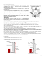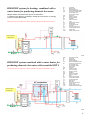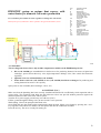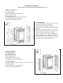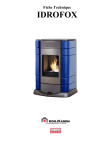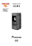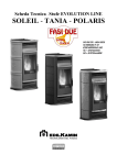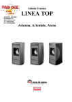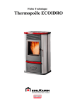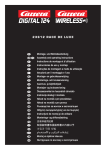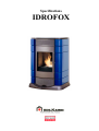
1
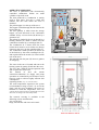
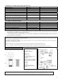
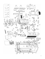
Specifications
IDROFOX
Dear Sir or Madam,
thank you for choosing our Idrofox stove.
Before using your stove, please read this booklet carefully: it explains how to exploit all its features to the full in
complete safety.
For any further information or needs, contact toll-free number (from Italy)
+39 800-014142
Please remember that the 1st ignition MUST be carried out by a TAC (EdilKamin technical assistance centre
authorized according to Italian law 46/90), which inspects the installation and fills in the guarantee.
You can get a list of centres by visiting the contacts page on the EdilKamin web site www.edilkamin.com or by
calling the toll free number shown above.
The manufacturer cannot be held liable for any damage which may derive from using the stove after incorrect
installation, incorrect maintenance or misuse.
SAFETY INFORMATION
THE STOVE MUST NEVER BE RUN WITHOUT WATER IN THE SYSTEM.
“WATERLESS” IGNITION DAMAGES THE STOVE.
The stove is designed to heat water through the automatic combustion of pellets in a firebox.
The only risks which may derive from using the stove are linked with non-compliance with the installation
instructions, direct contact with live electrical parts (inside) or with the fire or hot parts, and the introduction of
foreign substances.
If components fail, the stove is fitted with safety devices which turn it off. This must be allowed to happen
without interference .
For correct operation, the stove must be installed in compliance with the instructions herein, and the
door must not be opened during operation: combustion is managed automatically so no manual
operations are needed.
Never put foreign substances in the firebox or hopper.
Do not use flammable products to clean the smoke duct.
Firebox and hopper components must only be cleaned WHEN COLD using a vacuum cleaner.
The glass must be cleaned when COLD with a special product (e.g. GlassKamin) and cloth. Do not clean when
hot.
During stove operation, the outlet pipes and door reach high temperatures.
Do not keep objects which are not able to withstand heat in the immediate vicinity of the stove.
NEVER use liquid fuels to light the stove or rekindle the embers.
Do not block ventilation openings in the room where the stove is installed or air inlets in the stove itself.
Do not get the stove wet, and do not put wet hands near electrical parts.
Do not fit reducers on the smoke outlet pipes.
The stove must be installed in a suitable place as regards fire regulations, and provided with all the facilities
(power supply and outlet) it requires for correct safe operation.
CE STANDARDS and COMPLIANCE DECLARATION
EdilKamin declares that the Idrofox stove complies with the following C.E. marking European Directives
73/23/EEC and later modification 93/68/EEC
89/336/EEC and later modifications 93/68/EEC, 92/31/EEC and 93/97 EEC
In the case of installation in Italy, refer to Italian standard UNI 10683/98 or later modifications. For the
domestic hot water and heating system, have the plumber issue a declaration according to Italian law No. 46/90.
In all other countries, check the laws and national regulations on the subject.
2
INDEX
Operating principle and reference dimensions
Specifications, fuel and wiring diagram
Exploded view with spare part codes
Role of main components (TAC)
Assembly and installation (TAC)
Water connections (TAC)
Possible system diagrams
Covering assembly
Interface: panel, remote control and pressure gauge
Use
Ignition
Operating modes
Switching off
Clock adjustment
Weekly programming
Servicing: routine and annual (TAC)
Advice in the event of problems
Frequently asked questions
Check list
p. 4
p. 5
p. 6
p. 8
p. 8
p. 10
p. 10
p. 13
p. 14
p. 14
p. 15
p. 15
p. 15
p. 15
p. 16
p. 17
p. 19
p. 20
3
OPERATING PRINCIPLE
The stove is pellet-fired with electronically
controlled combustion. Pellets are small
cylinders of pressed wood.
The heat produced by combustion is mainly
used to heat water, and only a small part
radiates into the room where the stove is
installed.
The pellet hopper is at the top of the stove.
The hopper is filled through the lid found at the
back of the top.
The fuel (pellets) is taken from the storage
hopper (A) and delivered to the combustion
chamber (D) by a screw feeder (B) driven by a
gearmotor (C).
The pellets are ignited by hot air produced by a
heating element (E) which is drawn into the
combustion chamber by a centrifugal fan (F).
The combustion air is drawn from the room
(where there must be an air intake not directly
connect to the stove) by the centrifugal fan (F).
The combustion smoke produced is drawn out
of the firebox by the same centrifugal fan (F),
and expelled from the nozzle (G) at the bottom
rear of the stove.
The ash falls into the pan (H) where it gathers
for emptying.
The water in the stove is heated and sent to the
heating system by pump (I) built into the stove.
The stove has a built-in closed expansion tank
and overpressure relief valve.
The
amount
of
fuel,
the
smoke
extraction/combustion air supply and pump
operation are controlled by an electronic circuit
board in order to achieve highly efficient fuel
consumption.
Operating modes (see p. 15 for further details)
The water temperature required in the system
(recommended average of 60°C) is set on the
panel, and the stove modulates the power to
maintain or reach this temperature. With small
systems, the Eco function may be enabled (the stove turns
off and on according to the water temperature).
The external covering is available in the
following colours and materials:
grey or red steel;
beige, Persian blue and wine-red ceramic
4
TECHNICAL AND HEATING SPECIFICATIONS
Hopper capacity
Overall efficiency
Water efficiency
Overall available power (min/max)
Power available for water heating (min/max)
Time between refuellings (min/max)
Fuel consumption
Heatable room dimensions only considering
heating by hot water and calculating 35 kcal/m3 h
Weight (steel/ceramic)
Smoke duct diameter
ELECTRICAL SPECIFICATIONS
Power supply
On/off switch:
Average power consumption
Average power consumption during ignition
Remote control frequency
Protection on mains power supply
Electronic circuit board protection
•
•
35
Up to 90
Average of 79-80
4.5/18.5
3.5/15
9/35
1/4
80/ 360
kg
%
%
kW
kW
hours
kg/h
m3
200/225
8
kg
cm
230VAC +/- 10% 50 Hz
yes
300
400
infrared
5 x 20 2A 250 VAC fuse
5 x 20 2A 250 VAC fuse
W
W
The heatable room dimensions are calculated assuming the use of pellets of the type described in the note, and home
insulation which complies with Italian law No.10/91.
A LOT DEPENDS ON THE EFFICIENCY OF THE HEAT EMITTING UNITS (RADIATORS). Bear in mind that
more than 15 kW is NOT needed.
NOTES on fuel.
The Idrofox pellet stove is designed and programmed to burn pellets.
Pellets are small 6 mm diameter (approx.) fuel cylinders made from sawdust and ground waste wood pressed at high pressure without adhesives or other
foreign material. They are sold in 15 kg bags.
In order NOT to jeopardize stove operation, do NOT burn other substances. The use of other materials (including wood), which can be detected by
laboratory analyses, invalidates the guarantee.
EdilKamin has designed, tested and programmed its stoves to perform best with pellets with the following characteristics:
diameter: 6 - 7 millimetres; maximum length: 40 mm; maximum moisture content: 8 %; heat output: 4300 kcal/kg (at least)
Use of unsuitable pellets may lead to: a decrease in efficiency; operating anomalies; stoppages due to clogging, dirty glass, unburnt fuel, etc.
Remember to comply with fire safety distances
See p. 9
WIRING DIAGRAM
CONTROL PANEL
MAINTENANCE RS232
AUX
SMOKE RPM
IN T J
WATER OUTLET
TEMPERATURE DETECTOR
LITHIUM BATTERY
2A FUSE
230 V AC 50 Hz +/- 10% MAINS
SMOKE EXTRACTION MOTOR
IGNITION HEATING ELEMENT
120°C TM
2A FUSE
90°C TM
∆P 40 Pa
SCREW FEEDER MOTOR
WATER CIRCULATION PUMP
2A FUSE
AUX PORT
The TAC may install a device for remote on/off operation on the electronic circuit board (the AUX port).
5
6
Item
Description
Code
Num of
pcs.
Ite
m
Description
Code
Num of
pcs.
Ite
m
Description
270870
Num
of
pcs.
1
Left
covering
fastening
shoulder
Electronic circuit board
Power supply cable
Electric cable kit
Remote control
3/8" air bleed valve
271480
230210
271490
232730
269550
1
1
1
1
1
269560
269570
269670
269520
269510
269540
1
1
1
1
1
1
269500
1
94
Automatic air bleed valve
1/2" M/F safety valve
20 mm diam. 3/4" outlet pipe
3 bar safety valve
25/50 circulation pump
100°C
water
safety
thermostat
mod. 8-7508 3/4" closed
expansion tank
Anti-vibration rubber bung
234420
4
95
3/4" pipe nipples
269640
4
269710
269650
269700
269660
269580
1
2
1
1
1
272160
269690
269680
1
1
1
235210
261980
270620
270200
197560
272540
238030
199040
1
5
1
1
1
1
1
1
271500
6630
196500
261320
272310
269600
269570
1
1
1
1
1
1
1
119
120
121
Outlet pipe 2
1/2" M 1/2" F bend
Outlet pipe 1
Inlet pipe
Sleeving
for
capillary
instruments
1/2" M 3/8F connector
Connecting pipe
Expansion tank connecting
bend
Power socket with switch
3/4" pipe fastening nut
Lower rear panel
Upper rear panel
Door handle
Flat cable
Pressure switch
Silicone tube for pressure
switch
Water temperature detector
Reversible EK glove
Scraper
Desiccant crystals
Pipe cleaner with brush
Small check valve
Male/female ISO228 safety
valve
3/4" gasket
1/2" gasket
1" gasket
262010
262020
269620
7
1
2
122
1 1/2" silicone rubber gasket
262030
2
1
Anti-vibration feet 40 x 25 x 8/70 shr
274040
4
38
Upper loader cover
247480
1
81
2
3
4
5
6
Metal frame
Ash pan
Ash guard
Upper cast iron grille
Duct cleaning scraper
264490
270310
271570
270860
272450
1
1
1
1
1
39
40
41
42
43
247330
255360
270350
270690
249010
1
1
1
1
2
82
83
84
85
86
7
8
9
10
11
12
M5 nut
Front inspection panel
Scraper knob
Front cleaning scraper
Rear scraper
Duct cleaning cover
8880
270930
252330
272390
272523
272530
4
1
2
1
1
1
44
45
46
47
48
49
Screw feeder half cover
Screw feeder safety thermostat
Loader body
Pellet outlet gasket
Teflon coated bush for screw
feeder
Screw feeder shaft
Ceramic paper loader gasket
Lower shaft locking flange
Gearmotor locking bush
MK2 gearmotor, rpm
Smoke probe thermocouple
249343
247380
247320
232580
237900
255370
1
1
1
1
1
1
87
88
89
90
91
92
13
10 x 2 black adhesive gasket
425810
L=0.7 m
50
Internal pellet chute cover
271780
1
93
14
Stainless steel TCL screws/ M5 x 16
hexagonal slot
Lower top
206350
2
51
Smoke extractor
215130
1
15
270660
1
52
201010
1
16
17
18
19
20
Spacers
Intermediate top
Cast iron upper inspection cover
Silicone rubber bung
Upper top
196370
270340
270770
216510
270330
4
1
1
2
1
53
54
55
56
57
255090
201020
270280
270300
363820
1
1
1
1
1
96
97
98
99
100
21
22
23
Pellet cover hinge
Pellet cover
Display-control switch
270680
270320
232720
2
1
1
58
59
60
Smoke motor ceramic paper
gasket
Cast iron smoke outlet spiral
Smoke duct gasket
Smoke duct
Smoke duct cover
Internal combustion chamber
divider
Combustion chamber
Ash grate
Combustion chamber door
270900
270980
270290
1
1
1
101
102
103
24
25
26
27
28
29
30
30
Pressure gauge
Lower door fastening bracket
Left upright
Right upright
Left base
Right base
Grey steel panel
Red steel panel
269590
270820
270910
270920
190420
190410
197600
197590
1
1
1
1
1
1
2
2
61
62
63
64
65
66
67
68
Ignition heating element
Ignition heating element bush
Cast iron door
13 mm diam. door gasket
Upper M10 adjustment pin
M5 x 20 nut
Handle fastener
TSP screw/5 x 20 hexagonal slot
248510
247350
269040
224660
270560
44830
194440
246130
1
1
1
L=1.9 m
1
1
1
2
104
105
106
107
108
109
110
111
31
31
31
32
32
32
33
13.5 h Persian blue ceramic side
13.5 h beige ceramic side
13.5 h wine-red ceramic side
40 h Persian blue ceramic side
40 h beige ceramic side
40 h wine-red ceramic side
Ceramic covering fastening bracket
201410
213230
213210
201420
213240
213220
166490
8
8
8
2
2
2
8
69
70
71
72
73
74
75
D.8 corrugated washer
Left glass holder
Glass
Right glass holder
Upper glass holder
Air conveyor
Lower M10 adjustment pin
162470
270710
193630
270720
271770
270730
270570
2
1
1
1
1
1
1
112
113
114
115
116
117
118
33
34
35
Metal covering fastening bracket
Pellet protection grille
Rear pellet hopper wall
166490
270790
270580
4
1
1
76
77
78
269060
270810
224660
1
1
L=1.020 m
36
37
Pellet hopper
6 mm diam. plait gasket
270830
254040
1
L=0.78
79
80
Lower cast iron front panel
Lower front panel handle
13 mm diam. lower front panel
gasket
8 x 2 black adhesive gasket
Right covering fastening shoulder
173050
270880
L=1.3 m
1
Code
7
ROLE OF SAFETY DEVICES AND DETECTORS fitted to the stove
• Smoke thermocouple: on the smoke outlet. It reads the smoke temperature. It regulates the ignition
stage and shuts the stove down if the temperature is too high or too low (flame stop or excessive smoke
temperature stop respectively).
• Pressure switch: It measures the pressure near the smoke extractor and stops pellet loading by cutting
off the electricity supply to the gearmotor if the pressure is insufficient (due to INsufficient smoke outlet
or the stove door being open).
• Screw feeder safety thermostat: found near the pellet hopper. It starts a shutdown if the temperature
detected is too high.
• Water temperature detector: It reads the water temperature in the stove and sends the circuit board
information for pump management and stove power modulation.
If the temperature is too high, it starts a shutdown.
• Water temperature safety thermostat: It reads the water temperature in the stove. If the temperature is
too high, it starts a shutdown by cutting off the electricity power supply to the gearmotor. If it has
tripped, it may be reset by pressing the reset button behind the stove.
• Overpressure valve: when the rated pressure is reached, it drains water from the system thus creating
the need for a top up.
• Pressure gauge: found under the pellet loading lid. It shows the water pressure in the stove
IF THE STOVE SHUTS DOWN, THE REASON APPEARS ON THE DISPLAY AND IS STORED IN THE
MEMORY.
ROLE OF STOVE COMPONENTS
•
•
•
•
•
•
•
•
Ignition heating element: It ignites the pellets. It remains on during the ignition stage until the smoke
temperature increases by 15°C.
Smoke extractor: It “pushes” out the smoke and draws in fuel air through the vacuum it creates.
Gearmotor: It moves the screw feeder and loads pellets from the hopper into the combustion chamber.
Pump: It “pushes” the water out into the system.
Closed expansion tank: it “absorbs” the changes in water volume in the stove.
o !A separate expansion tank should be provided for the system!
Automatic bleed valve: found in the upper part. It may be used to “bleed off” any air
Manual bleed valve: found in the upper part. It may be used to “bleed off” any air
Drain cock: found inside the stove at the bottom; it should be used to empty the boiler-stove of water.
ASSEMBLY AND INSTALLATION (TAC - technical assistance centre)
Refer to the local regulations in the country of use for anything not expressly shown. In Italy, refer to Italian
standard 10683/1998 or later modifications, and Italian law No. 46/90 along with any regional or local health
authority regulations. If the stove is to be installed in a block of flats, consult the block administration before
installing.
COMPATIBILITY CHECK WITH OTHER DEVICES
According to Italian standard UNI 10683/98, the stove must NOT be installed in the same room as extractor fans,
type B gas equipment or devices which lower the pressure in the room.
ELECTRICAL CONNECTION CHECK (THE PLUG MUST BE IN AN ACCESSIBLE PLACE)
The stove is fitted with an electrical power cord for connection to a 230 V 50 Hz socket, preferably
protected with a thermal-magnetic circuit breaker. Voltage variations of greater than 10% may impair
stove operation (if not already installed, fit a suitable residual current circuit breaker). The electrical
system must comply with the law; in particular make sure the earth circuit is in working order. The
power supply line must have a suitable cross-section for the equipment rating.
LOCATION
For correct operation the stove must be level.
Check the load-bearing capacity of the floor.
8
FIRE SAFETY DISTANCES
The stove must be installed in compliance with the following safety
conditions:
- minimum safety distance at the sides and back from medium-level
flammable materials: 40 cm
- easily flammable materials must not be located less than 80 cm from the
front of the stove
- if the stove is installed on a flammable floor, a sheet of heat insulating
material must be placed between the stove and the floor, which protrudes
by at least 20 cm at the sides and 40 cm at the front.
Objects made of flammable materials must not be placed on the stove or at
less than the safety distance from it.
If the smoke outlet pipe is connected to walls made of wood or other
flammable materials, it must be insulated with ceramic fibre or other
materials with similar characteristics.
AIR INTAKE
The room where the stove is located must have an air intake with cross
section of at least 80 cm2 to ensure replenishment of the air consumed by
combustion.
SMOKE OUTLET
The stove must have its own smoke outlet (it must not discharge into common flues or other devices).
The smoke leaves the stove through the 8 cm diameter pipe at the back.
A T-section with condensation trap and bleeder must be fitted at the beginning of the vertical section.
The stove smoke outlet must be connected with the outside using black painted or steel pipes (resistant to
450°C), without obstructions.
The pipe seals must be air-tight. To seal and insulate (if necessary) the pipes, material that withstands up to
300°C must be used (silicone or high temperature mastic).
The horizontal sections may be up to 2 m long. Up to three 90° bends may be included.
If the smoke outlet does not end in a flue, a suitably fixed vertical section (at least 1.5 m long unless clearly
unadvisable for safety reasons) with wind guard at the end is essential. The vertical duct section may be indoor or
outdoor. If the smoke duct is outdoor, it must be insulated.
If the smoke duct ends in a flue, the flue must be authorized for solid fuel. If it is more than 150 mm in diameter,
it must be renewed by inserting an internal pipe and sealing the smoke outlet from the brickwork.
All sections of the smoke duct must be inspectable. If it is fixed, cleaning inspection openings must be provided.
The recommended installations are those shown in the following figures.
Smoke
1.5 m minimum h
Air intake from outside to room (minimum internal section: 80 cm2)
Brick-built flue
Air intake from outside to room (minimum internal section: 80 cm2)
9
WATER CONNECTIONS (by authorized TAC)
THE STOVE MUST NEVER BE RUN WITHOUT WATER IN THE SYSTEM.
“WATERLESS” IGNITION DAMAGES THE STOVE.
Plumbing must be carried out by qualified staff authorized to issue declarations of conformity in compliance with
Italian law No. 46/90.
Water treatment
Add antifreeze, scale inhibitors and corrosion inhibitors. If the top-up water has a hardness greater than 35°F, use
a water softener to reduce it. Refer to Italian standard UNI 8065-1989 (Water treatment in domestic heating
systems).
Practical NOTE
When connecting the outlet, inlet and drain piping (see page 4), fit suitable means to make moving the stove easy
in the future (for example, flexible piping for the first 0.5 m)
A few possible indicative system designs are shown below.
Idrofox system as unique heat source.
This layout is purely indicative. Have a plumber design and install the system
IDROFOX system as unique heat source.
This layout is purely indicative. Have a plumber design and install the
system.
AF:
AL:
C:
GR:
MI:
P:
RA:
RI:
S:
ST:
TS:
V:
VA:
Vec:
VSP:
VST:
Cold water
Water supply
Filling/Topping up
Filling unit
Outlet to system
Pump (circulator)
Radiators
Inlet from system
Drain
Temperature detector
Boiler-Stove
Ball valve
Automatic bleed valve
Closed expansion tank
Safety pressure valve
High temperature drainage valve
Internal stove
components
10
IDROFOX system for heating, combined with a
water heater for producing domestic hot water.
Idrofox and the water heater must operate as alternatives.
A suitable system must be provided for turning the water heater on and off
(such as a contact thermostat)
This layout is purely indicative. Have a plumber design and install the system.
AF:
AL:
C:
CA:
EV3
GR:
MI:
P:
RA:
RI:
S:
ST:
TS:
TC:
V:
VA:
Vec:
VR:
VSP:
Cold water
Water supply
Filling/Topping up
Wall mounted water heater
Three-way solenoid valve
NA: Normally open
NC: Normally closed
Filling unit
Outlet to system
Pump (circulator)
Radiators
Inlet from system
Drain
Temperature detector
Boiler-Stove
Contact thermostat
Ball valve
Automatic bleed valve
Closed expansion tank
Check valve
Safety pressure valve
Internal stove
components
IDROFOX system combined with a water heater for
producing domestic hot water with assembled KIT 4
This layout is purely indicative. Have a plumber design and install the system.
ACS:
AF:
AL:
C:
CA:
EV
F:
GR:
MI:
P:
PS:
RA:
RE:
RI:
S:
AC:
ST:
TC:
TS:
V:
Vec:
VR:
VSP:
VST:
Domestic hot water
Cold water
Water supply
Filling/Topping up
Wall mounted water heater
Three-way solenoid valve
NA: Normally open
NC: Normally closed
Flow switch
Filling unit
Outlet to system
Pump (circulator)
Detector housing
Radiators
Electronic regulator
Inlet from system
Drain
Plate heat exchanger
Temperature detector
Contact thermostat
Boiler-Stove
Ball valve
Closed expansion tank
Check valve
Safety pressure valve
High temperature drainage
Internal stove
components
11
IDROFOX system as unique heat source, with
water heater for domestic hot water production
It is essential to fit a suitable electronic regulator to manage the water heater.
This layout is purely indicative. Have a plumber design and install the system.
ACS:
AL:
B:
C:
EV2
EV3
GR:
M
MI:
P:
RA:
RE:
RI:
S:
SI:
TS:
V:
VA:
Vec:
VSP:
Domestic hot water
Water supply
Water heater
Filling/Topping up
Two-way solenoid valve
Three-way solenoid valve
NA: Normally open
NC: Normally closed
Filling unit
Mixer valve
Outlet to system
Pump (circulator)
Radiators
Electronic regulator
Inlet from system
Drain
Immersion probe
Pellet-fired boiler-stove
Ball valve
Automatic bleed valve
Closed expansion tank
Safety pressure valve
Internal stove
components
ACCESSORIES
The two diagrams shown above only include components available on the EdilKamin price list
•
•
•
Kit 4 (cod. 264290) pre-assembled kit for boiler-stoves for producing domestic hot water (20 plate heat
exchanger, power-driven three-way valve, high temperature drainage valve, flow switch and electronic
regulator.)
Optional extra for wall installation (cod. 262140)
Water heater with one (cod. 264750) or two (cod. 264760) fixed heat exchangers for producing and
storing domestic hot water. 150 l capacity.
Spare parts are also available (heat exchanger, valves, etc.)
1st IGNITION (TAC)
Make sure that the plumbing has been correctly installed and fitted with a sufficiently sized expansion tank to
assure safety. The expansion tank built into the boiler-stove does not provide suitable protection against the
thermal expansion of the water in the whole system.
Turn the stove power supply on and carry out cold tests (TAC).
Fill the system through the filling valve (do not exceed 1 bar in pressure)
While filling, “bleed” the pump and the bleed valve.
Once filled and once the smoke outlet connection has been checked, fill the screw feeder by pressing the + and –
keys together. After about five minutes, the first pellets fall into the combustion chamber.
Press the 0/1 key. The stove is ready for turning on.
12
COVERING ASSEMBLY
The spare part codes are shown on the exploded view on p. 7
CERAMIC IDROFOX
Covering parts list:
ceramic part fastening bracket guides
right cast iron base (29)
left cast iron base (28)
8 fastening brackets for side ceramic parts (33)
8 13.5 h small side ceramic parts (31)
2 40 h large side ceramic parts (32)
Covering assembly
After positioning the frame as shown in the
previous section, proceed as follows:
Centre the base parts against the frame.
Put the first of the small pieces from the bottom
in place
Screw the first fastening bracket to the metal
guides already fixed to the stove, and slip the
lower pin into the small ceramic side part.
Put the second small ceramic component in
place by slipping it into the bracket. Screw a
fastening bracket to the metal guide and slip its
lower pin into the small ceramic part. Proceed
in a similar way up to the top of the stove.
STEEL IDROFOX
Covering parts list:
left cast iron base (28)
right cast iron base (29)
2 steel side parts (30)
[interchangeable right and left]
4 fastening brackets for steel parts (33)
Covering assembly
After positioning the frame as shown in the previous section,
proceed as follows:
Centre the base parts against the frame.
Slip the side parts onto the frame.
13
cTHE INTERFACE
Panel with display and 4 keys :
0/1: to turn on and off
Menu: to access the menu
+/-: to increase/decrease the various settings
Remote control
To use the remote control, point it towards the stove. A beep confirms command reception, which is
also confirmed by the command taking place.
4 keys (0/1, menu, + and -) to turn on and off and increase/decrease the temperature.
The most frequent cause of remote control malfunction is flat batteries. Replace and dispose of old
batteries.
Pressure gauge
It is mainly useful to technicians.
It is found under the pellet loading lid and shows the water pressure in the system.
USE
Before ignition. 1st Ignition: contact your local TAC (technical assistance centre).
The first few times the stove is ignited there may be a slight smell of paint, which disappears rapidly.
Before ignition, check:
• that the stove has been installed and water connected correctly (make sure the system has been bled)
• the electrical power supply (turn the switch on the electrical socket to 1)
• the door is closed.
• the combustion chamber is clean.
• the display is on standby (date and time).
SCREW FEEDER LOADING.
If the pellet hopper empties, press the + and - keys together to fill the screw feeder.
This must be done before igniting the stove again if it has shut down due to running out of pellets.
It is normal for a few pellets to be left in the hopper, which the screw feeder is not able to pick up.
IGNITION
Automatic ignition
Hold the 0/1 key down for two seconds with the stove on standby to start the ignition procedure. The word Start appears on
the display for a few minutes (ignition does not take a preset time: it is automatically shortened if the electronics detect that
certain tests are passed). The flame appears after about five minutes. It is normal for a little smoke to be seen in the
combustion chamber before the flame appears. Start remains on the display until the flame is stable.
Manual ignition
At temperatures of less than 3°C (too low for the heating element to glow) or if the heating element is temporarily out of
order, a firelighter may be used for ignition. Put a piece of well lit firelighter into the combustion chamber, close the door
and press the 0/1 button.
14
OPERATING MODES
Set the water temperature required in the system (60°C recommended) on the panel. The stove modulates the
power to maintain or reach this temperature.
The Eco function may be enabled for small systems (see TAC adjustments). In this case, the stove turns off when
the water reaches the set temperature and turns back on again to modulate the power.
Switching off
Hold the 0/1 key down for two seconds while the stove is operating. The shutdown starts and the word Off
appears on the display (for 10 minutes).
During shutdown:
• Pellet loading ceases.
• Ventilation turns up to maximum
• The water circulates.
Never unplug the stove while it is shutting down
Clock adjustment
Hold the menu key down for two seconds to access the menu. The on-board clock operating parameters may be
set from this menu.
Weekly time programmer
Press the menu key for two seconds to access the time setting function and press + to access weekly time
programming: the message "timer on/off" appears on the display.
The stove may be programmed to come on and switch off automatically up to three times a day on each day of
the week.
Confirm with the "menu" key while the display shows "timer On/off". One of the following messages appears:
NO PROGRAM (not programmed)
DAILY PROGRAM (programmed to do the same thing every day)
WEEKLY PROGRAM (programmed differently for each day)
You can go from one to another using the + and - keys.
Confirm the "DAILY PROGRAM" option with the menu key to choose the number of programs (on/off) per day.
If you confirm "DAILY PROGRAM", the program(s) set will be the same every day of the week.
After confirming "WEEKLY PROGRAM", choose the day the program applies to:
1 Mon, 2 Tue, 3 Wed, 4 Thu, 5 Fri, 6 Sat and 7 Sun
Once the day has been selected using the + and - keys and confirmed with the menu key, continue in the same
way as for the "DAILY PROGRAM". Choose the number of programs and the times for each day of the week.
If you make a mistake while programming, you can exit by pressing the 0/1 key: the display shows "Saved".
Change pellet load
Press the menu key for two seconds and scroll through the items using the +/- keys until "adj.pellet" appears on
the display.
Confirm this item by pressing the menu key. The pellet load setting appears. This function may be useful if the
type of pellet the stove has been calibrated for is changed, thus making load adjustment necessary.
If adjusting this setting is not sufficient, contact the TAC (technical assistance centre) for a new operating setup.
COLD TEST (I/O TEST)
This menu is only accessible when the stove is on standby. It is used to check the components.
It may only be accessed by authorized TAC (Technical Assistance Centre) staff: a password is required.
Parameter adjustment
Press the menu key for two seconds and scroll through the items using the +/ - keys until "setup" appears on the
display. The main stove parameters may be adjusted on this menu. It may only be accessed by authorized TAC
(Technical Assistance Centre) staff: a password is required.
15
SERVICING
After 2500 kg of pellets are consumed, the display shows the word "Services???”.
The stove does NOT stop, but announces the need for servicing by a TAC.
Regular maintenance is essential for good stove operation.
IMPORTANT: USE THE CLEANING RODS
Before carrying out any maintenance, disconnect the device from the mains power supply
DAILY CLEANING
Clean with a vacuum cleaner. The whole process only takes a few minutes a day. Use the VACUUM CLEANER
when the stove is cold.
Remove front panel and operate front and rear scrapers (parts 10 and 11 on the exploded view on p. 6-7)
Open cover.
Use scraper provided (part 6 in the exploded view on p. 6-7) to clean heat exchange tubes in the firebox.
Vacuum clean hearth and vacuum clean the space around the combustion chamber where the ash falls.
Remove combustion chamber or clean it with a scraper, and unblock any blocked holes on all sides.
Remove and empty ash pan, and vacuum clean the underlying compartment.
Vacuum clean combustion chamber compartment, clean touching edges and replace combustion chamber.
If necessary clean glass (when cold).
NEVER VACUUM CLEAN HOT ASH
IT IS ESSENTIAL TO CLEAN THE HEAT EXCHANGE PIPES
16
EVERY SEASON (by the TAC - technical assistance centre)
The authorized TAC will give you a maintenance booklet after the first Idrofox stove ignition
General internal and external cleaning.
Carefully clean heat exchange pipes.
Carefully clean and descale combustion chamber and corresponding compartment.
Clean motors and mechanically inspect the play and fastenings.
Clean smoke duct (replace gasket on the smoke outlet pipe) and smoke extractor fan compartment.
Clean pressure switch and replace silicone tube.
Check expansion tank.
Check and clean circulator pump.
Check probes.
Replace clock battery on the electronic circuit board.
Clean, inspect and descale ignition heating element compartment and change heating element if necessary.
Clean/check display-control panel.
Visually inspect electric cables, connections and power cord.
Clean pellet hopper and check screw feeder-gearmotor assembly play.
Change door seal.
Test screw feeder loading, ignition, operation for ten minutes, and shutdown.
If the stove is used frequently, it is advisable to clean the smoke duct every 3 months.
ADVICE IN THE EVENT OF PROBLEMS
PROBLEM
CAUSE
display-control panel off
no mains voltage
remote control not working
Water not hot
excessive distance from stove
remote control batteries flat
too much soot in heat exchanger
SOLUTIONS
check power cord connection
check fuse (on power cord)
check flat cable connection to
display-control panel
move nearer to stove
check and change if necessary
clean heat exchanger from inside
the firebox
The chimney pots and smoke ducts connected to solid fuel devices must be brushed once a year (check whether there are regulations on
the subject in the country of installation). If inspection and regular cleaning are not carried out, the probability of a chimney pot fire
increases. In the event of a chimney pot fire, proceed as follows: do not use water to extinguish; empty pellet hopper; and contact
specialist staff after the accident before starting up again.
POSSIBLE CAUSES OF SHUTDOWN
If the stove shuts down, the reason is shown on the display.
1) Broken PTC H20: shutdown due to water temperature detector failure or disconnection
2) No expulsion: shutdown due to a fault detected by the smoke exhaust motor sensor
3) No fire: shutdown due to a drop in smoke temperature
4) No start: shutdown due to incorrect smoke temperature during ignition
5) Power failure: shutdown due to power failure
6) Termoc broken: shutdown due to thermocouple failure or disconnection
7) Over temp: shutdown when the maximum smoke temperature set is exceeded.
8) H2O temp alarm: shutdown due to a water temperature of above 90°C
The message is displayed until the 0/1 key on the panel is pressed.
Do not restart the stove until the problem has been looked into and the cause removed.
To start the stove up again after a shutdown, let the shutdown procedure end (10 minutes marked by a beep) then
press the 0/1 key.
Never unplug the stove while it is shutting down due to problems. It is important to report what the panel says to
the TAC (technical assistance centre).
17
ADVICE IN THE EVENT OF PROBLEMS
1) Broken PTC H20 (this trips if the water temperature detector fails or is disconnected)
Check connection between the detector and the circuit board. Check operation with cold tests.
2) No Expulsion (this trips if the smoke extraction speed sensor detects a fault)
- Check smoke extractor operation (speed sensor connection).
- Make sure the smoke duct is clean.
3) No fire (this trips if the thermocouple detects a smoke temperature lower than the value set, which it interprets
as the absence of flames)
There may be no flames because
- there are no pellets;
- too many pellets have smothered the flames;
- the maximum thermostat/pressure switch/water safety thermostat has tripped to “stop” the gearmotor.
4) No start (this trips if no flames appear and the start-up temperature is not reached within a maximum of 15
minutes).
There are two distinct cases
the flame does NOT appear
Flames appear, but after the word "Start", the message
"Start Failed" appears
Check:
Check:
- combustion chamber position and cleanliness;
- if the thermocouple is working;
- if the heating element is working;
- start-up temperature setting in the parameters.
- room temperature (if lower than 3°C use a firelighter)
and damp. Try to light with a firelighter.
5) Power failure
Check the electrical connection and for voltage drops
6) Termoc broken (this trips if the thermocouple fails or is disconnected)
Check connection between the thermocouple and the circuit board. Check operation with cold tests.
7) Over temp (shutdown due to excessive smoke temperature)
Excessive smoke temperature may be caused by: the type of pellet, smoke extraction fault, blocked duct,
incorrect installation, or gearmotor "drift".
8) H2O Alarm (this trips if the water temperature detector reads a temperature of above 90°C)
Excessive temperature may be caused by:
undersized system: have the TAC enable the ECO function;
clogging: clean exchange pipes, the combustion chamber and smoke outlet.
Pellets can NOT fall into the combustion chamber for the following reasons:
• There are no pellets: fill the hopper.
• The screw feeder is empty: fill the screw feeder by pressing the + and - keys together.
• Some pellets have jammed in the hopper: empty the pellet hopper with a vacuum cleaner.
• The gearmotor has broken down.
• The pressure switch has “disconnected” the electrical power supply from the gearmotor: check
installation, smoke duct cleanliness, and pressure in the extractor. Check using a volt-ohm-milliammeter
or fit a temporary jumper.
• The screw feeder safety thermostat has “disconnected” the electricity power supply from the gearmotor:
make sure there is no overheating. Check using a volt-ohm-milliammeter or fit a temporary jumper.
• The excess water temperature safety thermostat has “disconnected” the electricity power supply from the
gearmotor: check if there is water in the stove. Press the button behind the stove to reset. It is essential to
contact a TAC before starting up again.
18
FAQ
The answers shown here summarize the information found in these specifications.
1) What fittings do I need in order to install Idrofox?
Smoke outlet of at least 80 mm in diameter (the outlet must ONLY receive smoke from Idrofox).
Air intake in the room of at least 80 cm2.
¾” G manifold outlet and inlet.
¾” G outlet to drain for overpressure valve.
Coupling for ¾” G filling line.
Connection to an electrical system compliant with standards, with a 230V +/- 10% 50 Hz thermal-magnetic
circuit breaker.
Refer to page 4 for dimensions. Read the safe installation information on page 8.
THE FLUE MUST ONLY RECEIVE SMOKE FROM IDROFOX
2) Can I use the stove without connecting it to the domestic water system?
NO. Use without water damages the stove.
3) Does the Idrofox stove give out hot air?
NO. All the heat goes where it is needed: to the water. Part of the heat produced is radiated into the room. It is
advisable to fit the room with radiators.
4) Can I connect the stove inlet and outlet directly to a radiator?
NO, like all other water heaters, they must be connected to a manifold from which the water is distributed to the
heat emitting units (radiators).
5) Does the Idrofox stove also provide domestic hot water?
It is possible to produce it using our kit No. 4 (consisting of a heat exchanger, three-way valve, high temperature
valve and regulator) or produce it and store it with one of our water heaters (see plumbing diagrams). This use
reduces the power available to the radiators.
6) Can the Idrofox smoke outlet pass directly through the wall?
NO, there must be a vertical section of at least 1,5 metres. Otherwise, a small amount of smoke may be perceived
in the room in the event of power failure or wind.
THE FLUE MUST ONLY RECEIVE SMOKE FROM IDROFOX
7) Does there have to be an air intake in the room?
Yes, to replenish the air in the room. There is no direct connection between the air intake and the stove: the
smoke extractor draws air from the room and supplies it to the combustion chamber.
8) What do I have to set on the stove display?
The water temperature required: the stove modulates the power on the basis of this setting to attain or maintain it.
For small systems, the stove may be programmed to turn on and off according to the water temperature reached.
9) How often do I have to clean the combustion chamber?
Ideally before each stove ignition, while cold before turning it on. Clean the chamber AFTER CLEANING THE
PIPES WITH THE BRUSHES and operating the cleaning scrapers (see p. 16)
10) Should I vacuum clean the pellet hopper?
Yes, at least once a month or if the stove has not been used for a long time.
11) Can I burn other things apart from pellets?
NO. The stove is designed to burn pellets. Other materials may damage it.
12) Can I turn the stove on with a mobile phone text message?
Yes, if the TAC or an electrician has installed a suitable dialler (contact an electrical shop) at the electronic
circuit board AUX PORT (see p. 5).
19
CHECK LIST
Read the entire specifications before using this list
Installation and setup
•
•
•
Installation carried out by an authorized TAC which has issued the guarantee and maintenance booklet;
o Room ventilation;
o The smoke duct/flue only receives smoke from the stove;
o The smoke duct has:
no more than 3 bends;
a horizontal section of no more than 2 metres;
a vertical section of at least 1.5 metres;
o The outlet pipes are made of a suitable material (stainless steel is recommended);
o Where pipes cross any flammable materials (e.g. wood) all precautions have been taken to avoid
fire;
The plumbing has been declared as compliant with Italian law No. 46/90 by an authorized technician;
The heatable room dimensions have been suitably calculated considering the heating efficiency of the
heat emitting units (radiators).
Use
•
•
•
•
•
The pellets used are good quality and not damp;
The combustion chamber and ash pan are clean and have been placed correctly;
The cleaning rods are operated every day;
The heat exchange pipes are clean (use pipe cleaner);
The pressure (read on the gauge) is about 1 bar.
REMEMBER TO VACUUM CLEAN THE COMBUSTION CHAMBER BEFORE EACH IGNITION
If ignition fails, do NOT repeat ignition before emptying the combustion chamber
Via Mascagni, 7 - 20020 LAINATE (MI) - Italy
Tel. +39 02937621 – Fax +39 0293762400
www.edilkamin.com - [email protected]
EdilKamin S.p.A. reserves the right to modify parts of the following manual without prior notice:
cod. 272340 …-05.06/A
20