1
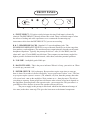
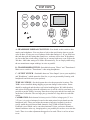
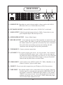
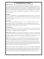
MANLEY
LABORATORIES, INC.
THE NEO-CLASSIC
300B PREAMPLIFIER
OWNER'S MANUAL
TUBES
RULE
brought to you by the clever folks at:
MANLEY LABORATORIES, INC.
13880 MAGNOLIA AVE.
CHINO, CA. 91710 USA
TEL: (909) 627-4256
FAX: (909) 628-2482
www.manleylabs.com
Rev. 10/08
CONTENTS
SECTION
PAGE
INTRODUCTION & GENERAL NOTES
3
MAINS CONNECTIONS
4
CONNECTING YOUR PREAMPLIFIER
5
FIGURE 1
FRONT PANEL
6
FIGURE 2
TOP VIEW
7
FIGURE 3
BACK PANEL
8
OPERATIONAL NOTES
9
SPECIFICATIONS
10
WARRANTY
11
WARRANTY REGISTRATION
12
2
INTRODUCTION
THANK YOU!...
for choosing the Manley Laboratories "The 300B Preamplifier". Handcrafted in Chino, CA, the Neo-Classic 300B
Preamplifier uses beautiful sounding parts in a clever and clean signal path. This Preamp features the 300B direct
heated triode as the line and headphone driver. The 300B is typically used in low power amplifiers as a power tube.
These 300B-based amps generally deliver 5 to 9 watts single-ended and cost from $3,000 to over $100,000! Some of
these amps sound very nice coupled with efficient speakers. Our Neo-Classic 300B SE/PP Power Amplifier uses a
pair of 300B’s that can be operated single-ended or push-pull, and delivers up to 22 watts. We consider the 300B to
be an extremely luscious tube for low-power purposes. Driving headphones and cables is a natural application for
these tubes. This is where the impedances are not too low and the power requirements are not too high but where
smaller triodes tubes might run out of steam. In our Neo-Classic 300B Preamplifier, we combine the classic 300B
with another classic - the octal-based 6SL7GT dual triode to perform the amplification duties. To complement this
tube choice we also employ tube-based rectification and regulation as well as our usual extreme filtering with gobs of
large filter caps.
To complement our best sounding line driver to date, we surround it with proven passive compnoents such as gold
plated connectors, high purity copper wire, Mil-spec printed circuit boards with extra thick copper and plating,
ceramic sockets, and custom-designed transformers. All the audiophile goodies are in here and together the sum total
is a beautiful sounding preamplifier which we know will provide years of faithful service.
LOCATION & VENTILATION
The Neo-Classic 300B Preamplifier must be installed in a stable location with ample ventilation. It is recommended,
if this unit is rack mounted, that you allow enough clearance on the bottom of the preamp such that a constant flow of
air can flow through the ventilation slots. The top should be given enough clearence to allow sufficient ventilation
above the tubes. We also recommend that the preamplifier be placed at least 10 inches away from its amplifier.
WATER & MOISTURE
As with all electronic equipment, this unit should be kept away from moisture of any kind. You’re allowed to weep
with joy at the sounds it makes, but keep those salty tears away from the power supply!
SERVICING
The user should not attempt to service the preamplifier beyond that described in the owner’s manual. Refer all
servicing other than tube replacement to Manley Laboratories.
SPECIAL NOTES
The 300B’s are packaged separately to prevent damage. You will need to carefully plug them in before powering-up
the preamp. Pay attention to the size of the pins to properly align the tubes before inserting. The large pins go into the
large sockets. It is difficult but possible to insert the 300B’s wrong and damage the preamp. Tubes may become loose
during transit. Straighten and press down each tube before plugging the preamplifier into the mains socket.
Furthermore, do not touch the tubes while the preamplifier is switched on, as the tubes do become very hot during
operation and should only be handled after the power has been turned off and the tubes have cooled.
Please read over this entertaining and enjoyable owner s manual carefully as it contains information essential
to the proper operation and maximum enjoyment of this instrument.
Thank you again, and please enjoy your new Neo-Classic 300B Preamplifier! (and the clever Owner s Manual.)
UNPACKING: Unpack the preamplifier carefully and make sure that all supplied accessories are present. Carefully
examine all items for any possibility of shipping damage. All the tubes should show no signs of distress such as
chipped glass, loose internal components or obvious breakage.
If the preamplifier is damaged or fails to operate, notify the shipper or your dealer or us or your local authorities
immediately. Or if you suspect The Shipping People threw it off the airplane and onto your front porch whilst flying
overhead at 30,000 feet, notify the shipping company without delay and complain to them as we only guarantee this
unit to be able to survive a drop of 23,487 feet or less.
Your Neo-Classic 300B Preamplifier was packed with extreme love and includes the following components and
accessories:
a) 1 each, 6 foot IEC 3-conductor power cable (that you will probably replace with an expensive audiophile cord
anyway.)
b) 1 each, Owner s Manual (that we hope you will keep reading.)
c) The tubes: 2 x 300B, 2 x 6SL7GT, 2 x OD3, and 2 x 5U4 vacuum tubes
It is prudent to retain the shipping materials for future use, as they are custom-formed for the preamp and
will greatly minimize the chance of shipping-related damage should you ever need to put your precious
Neo-Classic 300B Preamplifier in the careless hands of The Shipping People again.
3
MAINS CONNECTIONS
Your Manley Neo-Classic 300B Preamplifier has been factory set to the correct mains voltage for your country.
(Well, that is what we intended to do when we knew where it would be initially shipped.) The mains voltage
that we built this Manley Neo-Classic 300B Preamplifier to operate with is marked on the serial badge, located
on the rear panel. Check that this complies with what comes out of your wall.
There is no voltage changeover switch! There are jumpers on the power transformer PCB that are soldered to
put the transformer primaries in parallel for 117v operation or into series for 230/240v countries so be sure to
check the sticker and the serial number voltage indication for proper mains voltage. Failure to properly comply
with mains voltage requirements can cause extensive damage to the system, which of course would not be
covered by the warranty. If you relocate from, say, a 120v country to a 240v country, you will need to change
power transformer jumpers or use a step-up outboard converting transformer.
The mains fuse may be checked by first disconnecting the IEC mains cord from the power supply’s power inlet
plug. Then gently push and rotate counterclockwise the fuseholder retainer cap. The fuse and cap should spring
outward toward your fingers. Inspect the fuse for the proper rating; change if necessary. Refer to the fuse rating
chart in the specifications section of this manual. If you do not know what a blown fuse looks like, you may
measure for continuity across the fuse ends. If your meter reads “OL” when you measure across the fuse, that
means “Open Leads” and that would mean the fuse is blown. A blown fuse usually indicates A Very Bad Thing
occurred. If this has happened to you, try to figure out why it may have happened. (Using a Fast Blow fuse
when
we have specified a SLO-BLO fuse is one reason...) If you have no idea why a fuse might have just blown on its
own, you might want to consult with Manley Labs or your dealer for further advice as something Very Bad
might
have occured, like the power transformer might have decided to retire early.
One way this could happen is by running the wrong mains voltage into the unit. Be sure not to do that.
If you live in a strange place...
Export units for certain markets have a moulded mains plug fitted to comply with local requirements. If your
unit
does not have a plug fitted the coloured wires should be connected to the appropriate plug terminals in
accordance
with the following code.
GREEN/YELLOW EARTH terminal
BLUE NEUTRAL terminal
BROWN LIVE terminal
As the colours of the wires in the mains lead may not correspond with the coloured marking identifying the
terminals in your plug proceed as follows;
The wire which is coloured GREEN/YELLOW must be connected to the terminal in the plug which is marked
by
the letter E or by the safety earth symbol or coloured GREEN or GREEN and YELLOW.
The wire which is coloured BLUE must be connected to the terminal in the plug which is marked by the letter N
or
coloured BLACK.
The wire which is coloured BROWN must be connected to the terminal in the plug which is marked by the
letter L
or coloured RED.
DO NOT CONNECT OR SWITCH ON THE MAINS SUPPLY UNTIL ALL OTHER
CONNECTIONS HAVE BEEN MADE. (...or else...)
4
CONNECTING YOUR PREAMPLIFIER
Setting up your preamplifier is rather easy.
1. Please refer to page 8 for an illustration of the back of the preamplifier.
2. Connect the RCA outputs to the input of your power amplifiers when they are off.
3. UNBALANCED inputs are found on RCA jack inputs and can be connected to any line
level sources such as CD players, tuners or tape decks.
4. All RCA jacks are clearly labeled as to a typical function. Each input is, for all intents
and purposes, functionally and electronically the same. Only the labels are different.
5. The record output is not buffered and it is recommended that one have the tape feed
plugged into the REC OUT only when actually recording. Care should be used when
using a 3-head tape/monitor switch as this record out is not a tape loop.
6. On the left end of the back panel is a standard IEC mains connector. This should be
connected to a standard mains outlet with the supplied cable. This unit has been hardwired for the mains voltage in your country
7. Power up the preamplifier FIRST and allow it to settle for a minimum of 30 seconds
before powering up your amplifiers. Turn off your preamplifier and source components
LAST when powering down a system. This prevents amplification of turn-on transients
and other noises when powering up or turning a system off and ultimately protects the
speakers.
5
FRONT PANEL
HEADPHONES
VOLUME
OFF ON
AUX
TAPE
CD
TUNER
VIDEO
A
B
C
D
E
F
A - INPUT SELECT - 5 Position switch for input selection. Each input is electrically
identical. The RECORD OUT directly follows this switch. There is no buffer amp to isolate
the effects of loading and cable capacitance so we recommend disconnecting any
interconnect cables from the RECORD OUT if you are not recording.
B & C - HEADPHONE JACKS - Standard 1/4" stereo headphone jacks. The
HEADPHONE IMPEDANCE SWITCH (on top of the unit) should be set for the range that
best matches your headphones. The maximum power output primarily depends on the actual
headphone impedance. Typically the preamp can deliver 1 watt (10 volts RMS ) into 100
ohms and 1 watt (25 volts RMS) into 600 ohms. These outputs are transformer coupled for
highest possible isolation from shock hazards, cable shorts, and other potential problems.
D - VOLUME - Audiophile-grade Noble pot.
E - BACKLIT PANEL - This is the power indicator. When it is lit-up, your unit is on. When
it is not lit-up, your unit is off.
F - POWER SWITCH - Self explanatory. Because tubes require some time to warm up
there is about 10 seconds of silence followed by "not-so-good sound" before "wow". The best
way to power up the system is sources ( CD, turntable, etc) first, then this preamp, then after
a 30 second wait - turn on the amplifiers. Wait a minute or so - then play tunes. This allows
everything to warm up. Some people hear a difference after an hour or two but it depends on
the equipment. Powering down is the opposite order - power amps first. This procedure is a
good habit to follow because it stresses the speakers and ears the least.
The power supply in this preamp is tube based which has the inherant advantage of
slow start (as the tubes warm up). This gives the least stress to the internal components.
6
TOP VIEW
OD3
5AR4
or
5U4G
OD3
5AR4
or
5U4G
A
300B
300B
B
C
6SL7GT
6SL7GT
A - HEADPHONE IMPEDANCE SWITCH - You should set this switch to best
match your headphones. You may have to look at the specification sheet to get the
value in ohms. If using two sets of phones divide that number in 2. If you don't have
this info then pick the setting that sounds best - no harm will be done. If the phones
are lower than the switch setting, slight loss of extreme highs may occur. Expect the
300 ohm - 4000 ohm setting to be louder. Electronically, we are simply either using
the two transformer output windings in series or parallel.
B - TRANSFORMER SWITCH - Switchable between "Direct" and "Transformer".
Make sure to switch to "Transformer" when using headphones.
C - OUTPUT SWITCH - Switchable between "Line Output" (out to your amplifier)
and "Headphone" (which mutes the Line Out, as you are presumably listening with
headphones and don't need your speakers).
TUBE LOCATIONS - See the diagram above for the proper tube locations. The
300B's are not installed during shipping to prevent damage to these tubes. Power
should be unplugged and the tubes cool before handling them. We label the tubes
and sockets to help and so that the calibration we do will be valid in your home. It is
possible to put the 300B's in wrong. Note the two large pins and the two small pins
on the base of the tube. The two large pins go into the two large holes in each tube
socket.
CALIBRATION: Each channel is factory-set for 12 dB of voltage gain (1V in =
3.2V out ) via a pair of trimpots located on the main printed circuit board near the
headphone jacks. These pots adjust the amount of negative feedback in order to
exactly match the gain between both channels. Only 8.5dB of Global Negative
Feedback is used which can be considered minimal. Unless you hear a channel-tochannel imbalance after say, changing tubes, you probably do not have to re-trim the
levels. There is no other adjustment that needs to be made. There is no bias to have
to set.
7
REAR PANEL
F
C
D
E
A
B
G
J
H
I
A - MAINS FUSE - Depending on your local power outlet's voltage, replace with 3A SLOBLO fuse (120 V) or 1.5A SLO-BLO fuse (230V).
B - IEC MAINS SOCKET - Standard IEC mains socket (120/240 VAC as indicated)
C - MAIN OUTPUT - Main left and right outputs driven by 300B's. Connect these to your
power amplifier inputs when the amps are off.
D - SUBWOOFER OUTPUT - Same as Main Output.
E - RECORD OUTPUT - Set at input line stage level. These normally are connected to a tape
recorder's inputs. The signal is "picked off" the input selector and before
the volume control. It is a good idea to disconnect any wires connected to
these jacks when not recording to prevent extra loading and cable
capacitance from affecting the best possible performance.
F - TUNER INPUT - Connect your tuner outputs here.
G - AUX INPUT - This is where you plug your Aux in - no, not your cattle. "Aux" stands for
Auxilliary and basically means "extra", so this is just an extra input for
any other source that we didn't label or you have two of. Any of the input
jacks can be used with any Hi-Fi RCA outputs, as they are electrically
identical and only differ in how we labeled them.
H - VIDEO INPUT - Audio actually, from a DVD, Laserdisk, TV, VHS, or BetaMax (or, um,
whatever's current...) player's audio output.
I - CD INPUT - Plug in your audio outputs from your CD player or D/A Converter here.
J - TAPE INPUT - Tape machine outputs can be connected here. Be very careful - If the tape
machine inputs are connected to the preamplifier's RECORD OUTs and
the preamp is switched to TAPE and the tape machine is set to monitor
"INPUT" or you start to record - beware the dreaded squeal and howl of
feedback! One quick "cure" is to not select "TAPE" on the rotary input
selector if these other conditions are met.
8
OPERATIONAL NOTES
SWITCHING ON
The power knob is located on the right hand side of the front panel. Turn the knob to the right to
turn on the preamp, or to the left to turn it off. Don't ever rock it back and forth rapidly. Note: on
this knob and on the input selector there is a long garolite 1/4" rod shaft that connects the faceplate
knob to the actual switch in the back of the unit. If the knob starts spinning round and round then
the little screws on the shaft-to-switch coupler have come loose. If this happens to you, UNPLUG
the power from the unit, remove the bottom cover, and tighten the 4 x coupler screws with a 1/6"
hex key. No biggie.
RUNNING
It is not recommended that you leave your preamplifier permanently switched on. This only wastes
electricity and tube life. Your preamplifier has both tube and solid state rectification and reaches
peak operating condition in approximately 30 minutes. Also, running is good for your muscular and
cardiovascular health.
TUBE LIFE
As with all tubes, their quality degrades with age. This is due to cathode emission, a natural
process found in all tubes. We recommend that you have your preamplifier checked every 4-5
years, depending on usage. An excessive increase in noise level can indicate the need to replace the
6SL7 input tubes. 300B's usually last a very very long time..
HEADPHONES
Select the proper impedence for your headphones with the switch located on the top of the preamp.
Remember, when listening with headphones you MUST have the "Transformer" output selected,
not the "Direct" out. Headphones like the transformers a lot.
REPLACING A TUBE? Gently wiggle the tube while pulling it out of the socket. Before putting
a new tube in, look at it. Check to see that the pins are straight. Locate the "key" on the tube's center
locating pin and line that up to the key in the socket. You should be able to gently push the tube into
the socket without excessive force. You can wiggle it in a little bit as you push down.
HUM? This unit is meant to use the third pin of the mains as the ground reference. Many power
amps also use the third pin mains ground. Here we have a potential source of hum caused by
ground loops. Usually a hifi system will want to see the mains ground at only one place. Which
piece of gear should be grounded will have to be determined by experimentation using 3 pin to 2
pin "cheater" adapters on your power cords. Sometimes one power amp will be grounded and all
other gear will have adapters. Sometimes the better option is to ground the preamp and "float" the
amps. You will have to find out what works best in your system.
Another source of hum can come from equipment stacked on top of one another. Stacking gear too
closely can restrict airflow causing premature componentry failure and it is likely to introduce hum,
buzz or noise into the system. Some equipment can radiate strong magnetic fields outside of its
chassis and other gear may be prone to receiving the hum or buzz these fields can cause. You can
move units away from each other to hear if increased distance will solve a hum or buzz issue.
9
SPECIFICATIONS
*
*
*
*
*
*
*
*
*
*
*
*
*
*
*
*
*
*
*
*
*
*
*
*
*
*
*
*
*
*
*
*
Inputs: 5 stereo pair unbalanced RCA jacks
Outputs: 2 stereo pairs MAIN out same as SUB out unbalanced RCA jacks
RECORD output: 1 stereo pair pre-volume control unbalanced RCA jacks
HEADPHONE Outs: 2 front panel 1/4" headphone jacks
Optimized headphone impedance switching: 30-400 ohms to 300-4000 ohms
MUTE: Selecting HEADPHONE operation mutes LlNE outputs
Output Vacuum Tubes: 2 x 300B Electro-Harmonix
Input Tubes: 2 x 6SL7GT Electro-Harmonix
Rectifier Tubes: 2 x 5U4GBEH Electro-Harmonix or 5AR4 China
(Do NOT use the Sovtek 5AR4!)
Regulator Tubes: 2 x OD3 NOS JAN USA
Gain: factory set at 12 dB at max Volume
Internal Variable Feedback: 8.5 dB of global NFB is used @ 12 dB of gain,
adjustable trim -1.7dB to +1dB
Noise Floor: typically -70 dB (1 Hz - 100 KHz)
S/N Ratio: typically 105 dB (A WGT, 20 Hz - 20 KHz)
Frequency Response: 5 Hz to 50 KHz ±1dB
Channel-to-Channel Separation (L to R): @1KHz 48 dB; @10KHz 35 dB; @20KHz 34 dB
Channel-to-Channel Separation (R to L): @1KHz 50 dB; @10KHz 40 dB; @20KHz 37 dB
THD: 0.08 % @ 1KHz at 1V rms out
Distortion THD+N: -80 dB (.01 %) zero "crossover" distortion, mostly 2nd harmonic
Input Sensitivity: 250mV (-9.8dBu) yields 1V out
Input Impedance: 100 Kohm Noble volume control
Maximum Input Level: 5.5dBu or 1.459 Vrms @ 1KHz, volume control at maximum
Output Impedance (LINE STAGE): 100 ohms
Maximum Output Level: 17.2dBu or 5.636 Vrms @ 1KHz, volume control at maximum
Output Power (100 ohm Headphones): 1W (10 V RMS) (28 V P-P)
Output Power (600 ohm Headphones): 1W( 25 V RMS) (70 V P-P)
Power Consumption: 170 Watts (1.4 A @ 120VAC)
Operating Mains Voltage: Factory set for 100V, 120V or 220-240VAC operation for
original destination country's mains voltage.
Operating Mains Voltage: changeable with power transformer re-wiring and fuse value change.
Mains Voltage Frequency: 50~ 60Hz
Dimensions: W=19". L=13". H=3 1/2"
Shipping Weight: 28 Ibs.
10
WARRANTY
Manley Laboratories, Inc. WARRANTY STATEMENT effective 10/2008
All Manley and Langevin branded equipment designed and built by Manley Laboratories, Inc. is covered by a
limited warranty against defects in materials and workmanship for a period of 90 days from date the unit is sold
to the Dealer to the original purchaser only. A further optional limited 5 year transferable warranty is available
upon proper registration of ownership within 30 days of date of first purchase. This warranty cannot be
transferred outside of the USA in the case of secondhand purchases which are consequently exported.
Proper registration is made by filling out and returning to the factory the warranty card attached to this general
warranty statement, along with a copy of the original sales receipt as proof of the original date of purchase, or
registration can be made online in the Tech Support section of www.manleylabs.com.
This warranty is provided by the dealer where the unit was purchased, and by Manley Laboratories, Inc. Major
subassemblies that were not built by Manley Laboratories, Inc. specifically the SLAM! ADC/DAC/SRC digital
board designed and built by Anagram Technologies, SA of Switzerland will be warranted to the same terms the
supplier warrants the subassembly to Manley Laboratories, Inc. Under the terms of the warranty defective parts
will be repaired or replaced without charge, excepting the cost of consumables such as vacuum tubes and lamps.
Vacuum tubes and meter or badge lamps are warranted for six months provided the warranty registration is
completed as outlined above.
If a Manley Laboratories, Inc. product fails to meet the above warranty, then the purchaser's sole remedy shall
be to first obtain a Repair Authorisation from Manley Service Department and return the product to the Manley
Service Center, where the defect will be repaired without charge for parts and labour. All returns to Manley
Laboratories, Inc. or the Manley Service Center must be in the original packing, accompanied by the Repair
Authorisation, and must be shipped to the address specified on the Return Authorisation via insured freight at
the customer's own expense. Factory original packaging can be ordered from Manley Laboratories, Inc.
Customer will be charged for new factory original packaging if customer fails to ship product to Manley in the
original factory packaging. After repair, the product will then be returned to customer via prepaid, insured
freight, method and carrier to be determined solely by Manley Laboratories, Inc. Manley Laboratories, Inc. will
not pay for express or overnight freight service nor will Manley Laboratories, Inc. pay for shipments to
locations outside the USA. Charges for unauthorized service and transportation costs are not reimbursable under
this warranty, and all warrantees, express or implied, become null and void where the product has been
damaged by misuse, accident,neglect, modification, tampering or unauthorized alteration by anyone other than
Manley Laboratories, Inc. If a unit is received for warranty repair, and after complete examination and testing
no problem is found with the unit, customer will be charged for one hour of labor plus return shipping costs,
presuming initial user error falsely caused the unit to be determined faulty.
The warrantor assumes no liability for property damage or any other incidental or consequential damage
whatsoever which may result from failure of this product. Consequential component damage resulting from
vacuum tube failure in specific is not covered by warranty. Any and all warrantees of merchantability and
fitness implied by law are limited to the duration of the expressed warranty. All warrantees apply only to
Manley Laboratories, Inc. products purchased and used in the USA. All warrantees apply only to Manley
Laboratories, Inc. products originally purchased from an authorised Manley or Langevin dealer. Manley
Product that was not purchased through an authorised and legitimate sales channel is considered "Grey Market".
Warranties for Manley Products purchased outside the USA will be covered by the Manley Importer for that
specific country or region. Product originally sold to the USA market and consequently resold overseas forfeits
its warranty. American Manley Dealers are expressly forbidden to export Manley Product. "Grey Market"
purchases are not covered by any warranty. In the case that a Manley Product must be returned to the factory
from outside the USA, customer shall adhere to specific shipping, customs, and commercial invoicing
instructions given with the Return Authorisation as Manley Laboratories, Inc. will not be responsible for
transportation costs or customs fees related to any importation or re-exportation charges whatsoever.
Some states do not allow limitations on how long an implied warranty lasts, so the above limitations may not
apply to you. Some states do not allow the exclusion or limitation of incidental or consequential damages, so the
above exclusion may not apply to you. This warranty gives you specific legal rights and you may also have
other rights which vary from state to state.
For Tech Support and Repair Authorisation, please contact:
Manley Laboratories, Inc. Tech Support and Service
13880 Magnolia Ave. Chino, CA. 91710
Tel: +1 (909) 627-4256 x325
Fax: +1 (909) 628-2482
11
WARRANTY REGISTRATION
We ask, grovel and beg that you please fill out this registration form and send the bottom half to:
MANLEY LABORATORIES
REGISTRATION DEPARTMENT
13880 MAGNOLIA AVE.
CHINO CA, 91710 USA
Or you may FAX this form in to: +1 (909) 628-2482 or you may fill in the online warranty
registration form found in the Tech Support section of our website www.manleylabs.com or you can
be really diligent and register your warranty three times to see if we get confused!
Registration entitles you to product support, full warranty benefits, and notice of product
enhancements and upgrades, even though it doesn't necessarily mean that you will get them (Just
kidding!) You MUST complete and return the following to validate your warranty and registration.
Thank you again for choosing Manley gear and reading all the way through The Owner's Manual.
(We really mean that sincerely, the bit about thanking you for choosing our gear. THANK YOU!!!)
MODEL NEO-CLASSIC 300B PREAMP
SERIAL #__________________
PURCHASE DATE ______________ SUPPLIER ______________________
-------------------------------------------------------------------------------------------------------PLEASE DETACH THIS PORTION AND SEND IT TO MANLEY LABORATORIES
MODEL NEO-CLASSIC 300B PREAMP SERIAL #__________________
PURCHASE DATE ______________ SUPPLIER ______________________
NAME OF OWNER _______________________________________________
ADDRESS ______________________________________________________
CITY, STATE, ZIP ________________________________________________
EMAIL: ________________________________________________________
TELEPHONE NUMBER___________________________________________
COMMENTS OR SUGGESTIONS?__________________________________
________________________________________________________________
12