1
AES 7170 IP-Link
Transceiver
(Remote & Local)
Installation and Operation
Manual
40-7170 Revision 2B July 6, 2012
1
Table of Contents
1.0 Product Description: AES 7170 IP-Link System: ........................................................ 4
A. 7170 IP-Link Transceiver: ......................................................................................... 5
B. ASM Antenna Supervision Module (7170SWR) ....................................................... 6
C. Antenna(s): ................................................................................................................. 6
D. Cables and connectors: .............................................................................................. 6
E. AES 52-0054 Surge Suppressor(s): ............................................................................ 6
F. Internal Modem: ......................................................................................................... 6
G. Typical Unique Installation Tool Requirements: ....................................................... 6
2.0 Safety Considerations: .................................................................................................. 7
3.0 Environmental Considerations: ..................................................................................... 7
4.0 Technical Specifications: .............................................................................................. 7
5.0 Installation: ................................................................................................................... 8
A. 7170 IP-Link Transceiver Enclosure Mounting: ....................................................... 8
B. Antenna: ..................................................................................................................... 8
C. Coaxial Cabling and Connections: ............................................................................. 8
D. Surge Suppressor: .................................................................................................... 10
E. Grounding:................................................................................................................ 10
6.0 Wiring (Electrical Inputs and Outputs): ...................................................................... 11
A. Enclosure Label, Inside Cover: ................................................................................ 12
B. Terminal Block Connection Details: ........................................................................ 13
7.0 Indicators: ................................................................................................................... 14
A. Interface Board LEDs and Speaker: ........................................................................ 14
B. RF / Radio Control Board LEDs: ............................................................................. 14
8.0 Programming and Setup of the 7170 IP-Link Transceiver: ........................................ 16
A. Communicating with the 7170 IP-Link Transceiver: .............................................. 17
A.1. Configure Hyper Terminal (in Windows) to communicate with the 7170: ...... 17
A.2. Optionally, Configure Telix (in DOS) to communicate with the 7170: ........... 19
B. Initializing the 7170 IP-Link Transceiver: ............................................................... 20
Notes on the Shared Serial Port: ............................................................................... 20
RF Interference ................................................................................................................. 22
Editing files: .............................................................................................................. 22
C. Configuring the 7170 IP-Link Transceiver: ............................................................. 23
C.1. Edit the WATTCP.CFG file:............................................................................. 23
C.2. Configuring the TCP/IP parameters: ................................................................. 23
C.3. Set Up Menu: .................................................................................................... 24
C.4. Test the network connection: ............................................................................ 26
9.0 Testing the 7170 IP-Link Transceiver: ....................................................................... 27
A. Test Basic Board Functionality:............................................................................... 27
B. Test Local Board Functionality with terminal: ........................................................ 27
C. Test RF Signal: ......................................................................................................... 27
D. Test TCP/IP Communication Functionality: ........................................................... 28
E. Test RF Communication Functionality: ................................................................... 28
10.0 Warranty / Service Procedures: ................................................................................ 29
40-7170 Revision 2B July 6, 2012
2
40-7170 Revision 2B July 6, 2012
3
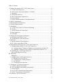
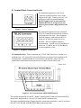
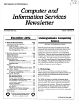
1.0 Product Description: AES 7170 IP-Link System:
MultiNet is an AES IntelliNet system that uses the Internet to forward received radio
signals to a central location. At the central location a MultiNet receiver is the central
controller. IP-Link Transceivers are deployed in local and or remote locations to collect
IntelliNet radio signals from Subscribers that are then forwarded using the Internet, local
network or backup modem, to the central MultiNet Receiver for processing and
distribution.
Figure A below illustrates a typical IP-Link system deployment.
Figure A. Typical IP-Link Network Configuration
The AES 7170 IP-Link System is available in a single or dual configuration. In a dual
configuration, the second IP-Link Transceiver acts as the backup. Each IP-Link
Transceiver will be configured to monitor and be monitored by a MultiNet receiver.
Detection of troubles and switching between primary and secondary is automatic.
This product shall be installed in accordance with NFPA 72,
NEC, UL 827 and all applicable local codes
40-7170 Revision 2B July 6, 2012
4
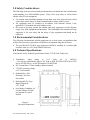
Following is a list and diagram of key components.
□
Transformer Specifications
Pri: 120VAC 60Hz
Sec: 16.5V 40VA or 45VA
Additional Transformer information
found on page 6 section 4
Figure B. Typical 7170 IP-Link Transceiver Installation
All wiring and installation must comply with relevant UL installation standards and local
buildings codes. Transformer and its wiring must be protected in conduit and in an AES
1640-ENCL enclosure. Unit must bonded to Earth Ground via the ground lug on PCB.
Customer shall be responsible for design of site-specific conduit detail including but not
limited to the usage of enclosures to house the IP-Link and Surge Suppressor for the
purpose of protecting transformer wiring in conduit.
A. 7170 IP-Link Transceiver:
The 7170 IP-Link Transceiver acts as a remotely installed hub or receiver that forwards
all the signals received from a cluster of AES Subscriber Units to an AES MultiNet
Receiver via a LAN, WAN, the Internet or a backup modem. The MultiNet receiver then
forwards the signals to the appropriate system. This allows the customer to expand their
geographical market reach without direct radio connectivity to the Central Station
Receiver. For AES customers with busy networks, the MultiNet system provides
significantly increased capacity for their IntelliNet system without adding a new
frequency. It also allows adding a new frequency to a RF congested area.
It is housed in a rugged NEMA style enclosure for positioning near the antenna. This
assures minimal RF loss from longer coaxial cables. A battery for backup is located in
the same enclosure. The battery powers the IP-Link Transceiver in event of a power
failure. It also, more efficiently provides extra current the transceiver needs when
transmitting. As with any AES central station receiver a Surge Suppressor is
recommended. Flanges are provided for wall mounting. Approximate enclosure size is
14”h x 11.5” w x 6”d.
40-7170 Revision 2B July 6, 2012
5
B. ASM Antenna Supervision Module (7170SWR)
This module is placed in series with the RF connection between the transceiver and the
antenna connector and allow the detection of antenna cut by measuring the SWR. It is
powered from the board stack. When the antenna is cut, it issues a signal to the board
stack that process it and issues a message to the Multinet Receiver. Upon antenna
reconnection, a restoral is issue after a pre-defined time has been elapsed without any
detection of antenna cut.
C. Antenna(s):
Rugged large antenna to maximize the range of the Base station IP-Link Transceiver.
Size and gain vary according the installation requirements and radio frequency. Typical
size for a UHF antenna is approximately 8 feet in height, with 9db gain.
The use of High Gain Antennas is approved for use in a UL installation or for NFPA 72
compliance.
D. Cables and connectors:
Low-Loss RG-8 (Belden 9913 type) coax cable is supplied with appropriate “N- Type”
connectors for maximum performance.
E. AES 52-0054 Surge Suppressor(s):
A device installed in the coaxial transmission line to help protect components and
structure against surges like those produced by lightning. The device dissipates surges to
an earth ground that is connected to the devices’ mounting bracket. Use only AES part.
F. Internal Modem:
IP-Link’s are equipped with an internal Modem for backup communication when TCP/IP
communication is delayed or unavailable. During the IP-Link’s initialization process the
modem is tested using both programmed phone numbers. During those tests the Modem
LED will be on and the Console Port unavailable. If either number fails to connect to an
assigned MultiNet Receiver, it will be re-tested randomly every 5 to 10 minutes until it
passes or the maximum number of 5 attempts is reached.
If during normal operation TCP/IP heartbeat fails, the IP-Link’s RF goes offline
transmitting a “Receiver Not in Service” message. That message will notify other
IntelliNet devices to select a secondary IP-Link for communicating. The modem is again
tested, and if it passes any stored messages are passed to the MultiNet receiver and RF
goes back online by transmitting a “Receiver Ready” message. Until the TCP/IP
connection returns satisfactorily, communication to the MultiNet receiver will occur
using the modem. Sending of Alarm messages via modem are attempted immediately
after reception. All other less significant messages may be discarded.
The modem, using both phone numbers is tested daily. Interval between daily test
attempts is 24 hours plus a random number of minutes up to 30, after the preceding tests
pass. This means that the time of day that the daily modem tests occur, randomly
advance. This helps to spread out multiple IP-Link testing.
G. Typical Unique Installation Tool Requirements:
The primary tools required to install an IP-Link Transceiver are as follows.
Power or SWR Meter
Large Wire Cutters
Coax Connector Crimping Tool
RG-8U Coax Strippers
Serial Terminal or PC running a terminal program
40-7170 Revision 2B July 6, 2012
Weatherproof Tape
Silicon Sealant
6
2.0 Safety Considerations:
The following items are safety related precautions that you should take into consideration
when installing your AES IntelliNet system. They are for your safety as well as others
and the safety of your equipment.
•
•
•
Use caution when installing antennas to keep them away from electrical wires which
could cause serious injury or death if antenna makes contact with live wires.
All equipment must be installed in accordance with National Electric Code,
applicable UL Standards and local building codes.
Be certain to properly ground the antenna and surge suppressor to help dissipate
surges away from equipment and personnel. The grounding of the antenna and surge
suppressor is for your safety and the safety of your equipment and should not be
neglected.
3.0 Environmental Considerations:
The following environmental related suggestions are to help insure an installation that
will provide you with a system that will operate at its optimum long into the future.
• The provided AES 52-0054 surge suppressor should be installed in a weather tight
enclosure such as a UL Listed NEMA4 enclosure.
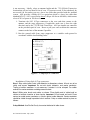
4.0 Technical Specifications:
Listed below are the technical specifications for the 7170 IP-Link Transceiver.
•
•
Transformer
Input
rating
is
16.5
Volts
AC
at
40/45VA
– Use only provided Model Amseco XF-1640 or ELK P/N ELK-TRG1640 or TDC
Power P/N DA-40-16.5 or MG Electronics P/N MGT1640
DC Current Draw: 370mA standby, 900mA transmit
•
7170 DC operating voltage
is 12 Volts nominal.
•
Onboard Fuse; Self
Resetting / Not User
Serviceable
•
Rechargeable Gel Type
Battery Required:
12V, 10AH
•
Low Battery Condition, AC
Fail and Charger Trouble
are reported to Central
Station.
Figure C –
Enclosure Dimensions
40-7170 Revision 2B July 6, 2012
7
5.0 Installation:
The IP-Link Transceiver installation site is a critical element of the AES IntelliNet
network. Every installation is unique, taking into account structure, geography and other
factors. This section covers elements of the system installation and operation. Read the
entire document before proceeding with your installation.
•
•
•
•
•
Read the Manual and any other provided documents.
Study each component to understand its mounting and installation characteristics.
Decide how each component be will be installed in your facility.
Proceed with the installation in a manner that serves your needs best.
Test your installation as outlined in section 8.
A. 7170 IP-Link Transceiver Enclosure Mounting:
Mount the enclosure on a steady permanent surface. A plywood backboard attached to a
wall works well. Locate it so that the coax runs to the antenna without tight bending,
kinking or producing strain on the coax and its connectors. Use mounting hardware of
appropriate size to support the weight of the enclosure.
B. Antenna:
It is a requirement in a commercial operation when growing a network to cover a large
area. For a professional installation, you can install the major components, run the
required cables, and then retain a qualified radio technician to perform the RF portion of
the installation:
1- Antenna, Mounts and connectors
2- All RF Connectors /Terminations
3- RF Lightning Suppressor / Grounding
4- Final check to assure that your installation is getting maximum performance.
Contact the radio technician BEFORE you begin any part of the installation, which is a
mix of science and art. Radio signal distance is in part related to the height of the
antenna. Select an antenna height that clears all or as many obstructions as possible. If
mounting on the side of a metal tower you should try to place the antenna at least 5 feet
off the tower if possible, with 2 ½ feet off the tower as the absolute minimum.
C. Coaxial Cabling and Connections:
The length of the coaxial cable is important. Coax causes loss of signal, the longer the
coax the greater the loss. You do not want to sacrifice signal loss for antenna height that
40-7170 Revision 2B July 6, 2012
8
is not necessary. Ideally, select an antenna height and the 7170 IP-Link Transceiver
location that will use less than 50 feet of coax. If you must exceed 50 feet absolutely do
not exceed 100 feet unless you use a lower loss cable than provided with the standard
system. AES provides a Belden 9913 or equivalent which is a lower loss cable than
standard RG-8/U. 9913 is specified as about 3 dB per 100 feet at 400 MHz, which means
a loss of 50% of power in 100 feet of coax.
1- Terminate the 9913 N-Type connectors at the coax ends that connect to the
antenna, and the surge suppressor, (if applicable, make sure it faces the right
direction) and to the 7170 IP-Link Transceiver. AES pre-installs one connector
on the provided spool of coax. Route or pull your coax such that this connector
connects to the base of the antenna if possible.
2- Run the ground cable from surge suppressor to a suitable earth ground in
accordance with the local building codes.
Strip Dimensions, inches (mm)
a: .0539 (13.7)
b: 0.250 (6.4)
c: 0.158 (4.0)
Figure E – Crimp Style N Connector
Installation of Crimp Style N-Type connectors:
Step 1 Strip cable jacket, braid, and dielectric to dimensions shown. All cuts are to be
sharp and square. Important: Do not nick braid, dielectric, and center conductor.
Tinning of center conductor is not necessary if contact is to be crimped. For solder
method, tin center conductor avoiding excessive heat.
Step 2 Slide outer ferrule onto cable as shown. Flare slightly end of cable braid as
shown to facilitate insertion of inner ferrule. Important: Do not comb out braid. Place
contact on cable center conductor so it butts against cable dielectric. Center conductor
should be visible through inspection hole in contact. Crimp or solder contact in place as
follows:
Crimp Method: Use Die Set Cavity for contact indicated in table above.
40-7170 Revision 2B July 6, 2012
9
Solder Method: Soft solder contact to cable center conductor. Do not get any solder on
outside surface of contact. Avoid excessive heat to prevent swelling of dielectric.
Step 3 Install cable assembly into body assembly so inner ferrule portion slides under
braid, Push cable assembly forward until contact snaps into place in insulator. Slide
outer ferrule over braid and up against connector body. Crimp outer ferrule using Die Set
Cavity specified in table above.
Installation of Clamp Style N-Type connectors:
This style connector is no longer provided by AES. The illustration is provided in case
you come across one.
Figure F – Solder Type N Connector
D. Surge Suppressor:
Install the Surge Suppressor in the coaxial transmission line outside to help keep surges
from entering the building. We recommend installing it in a user provided weather tight
enclosure or seal it from moisture with user provided sealant or weather sealing tape such
as self-fusing tape.
E. Grounding:
Attach a good earth ground to the surge suppressor and the antenna mounting bracket(s).
The grounding of the antenna and surge suppressor is for your safety and the safety of
your equipment and should not be neglected.
40-7170 Revision 2B July 6, 2012
10
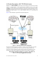
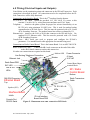
6.0 Wiring (Electrical Inputs and Outputs):
Listed below are the termination points and connectors in the IP-Link Transceiver. Each
connection is described in detail. All connections need to be completed before the IPLink Transceiver will be fully functional.
Connections on the Interface Board. This is the 2nd board up from the bottom.
J2 (16.5VAC) – AC Input. Attach the provided 16.5 VAC 40/45 VA source to this
terminal. Use min. 18 Ga., wiring between transformer and J2 AC Input.
Telephone –
Attach to the phone system for proper line seizure functionality via an
RJ-31X jack, using minimum 26 AWG wire. This is used for modem backup
communication to IP-Link Server. This line must be protected with a UL Listed
497A Secondary Protector. The modem feature has not been evaluated by UL.
Ethernet Jack – Attach to the LAN or WAN that connects to the IP-Link Server. Use
standard CAT-5 Ethernet cable. This line must be protected with a UL Listed
497B Secondary Protector.
Console Port – dB-9 Serial port used to program and configure the IP-Link’s
parameters. Use standard serial cable appropriate for terminal being used.
Connections on Radio Control Board. This is the bottom Board. It is an AES 7001 PCB.
Radio Transceiver Cable – Connect the dB-9 male connector on the end of this cable
to the dB-9 female connector on the radio transceiver.
No other user connections are required on this board.
Modem LED Power Connector
Line Seizing Telephone Connection
J2 Input
Modem
16.5 VAC
Ethernet Jack
Radio Reset PBS
Control Board Input
terminal Block
SVC LED
LNK & ACT
LEDs
RF / Radio
Control Board
Bottom
386 DOS Computer /
Radio Transceiver
Cable
Ethernet Board
Top
TX RX WA AL
LEDs
Speaker (SP1)
Interface Board
Middle
Console Port
RS-232 Serial
IP-Link Interface
Board Reset PBS
Figure G. Illustration of IP-Link Transceiver PCB Stack
40-7170 Revision 2B July 6, 2012
11
NOTE: DO NOT POWER UP THE IP-LINK TRANSCEIVER UNTIL ITS
MULTINET RECEIVER IS ON-LINE AND READY FOR THIS UNIT TO
ATTEMPT TO CONNECT.
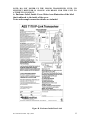
A. Enclosure Label, Inside Cover: Below is an illustration of the label
that is adhered to the inside of the cover.
Notes and example connection details are included.
Figure H. Enclosure Inside Door Label
40-7170 Revision 2B July 6, 2012
12
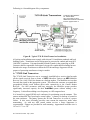
B. Terminal Block Connection Details:
The terminal designations for the Power
Connector terminal block are shown in the
diagram to the right. Connect your 16.5 VAC
transformer to the designated terminals.
DO NOT apply power to these until the
MultiNet Receiver is set up and you are
ready to proceed with configuration of this
Unit.
Figure I. Power Connector
The terminal designations for the Telephone
(TELCO) Connector terminal block are shown
in the diagram to the right. These terminals
should be properly connected to an RJ-31X
phone jack to allow for proper line seizer
functions. Refer to telephone company
documentation. T and R are to Tip and Ring of
phone line. T1 and R1 are for Tip and Ring to
premise telephones, if any.
Figure J. Telephone Connection
UL Installation Note: When connecting the 7170 IP-Link Transceiver’s modem to a
telephone line, a UL Listed 497A Secondary Protector is required to be installed on the
incoming lines. Installation shall be in accordance with the NEC Article 800, the
manufactures installation instructions and in accordance with all local codes.
Figure K. RF Control Board, Input terminal Block
The terminal designations for the RF / Radio Controller Board Connector terminal block are
shown in the diagram above. Use only UL listed 26AWG minimum wire.
The
factory
installed
40-7170
Revision
2B Enclosure
July 6, 2012Tamper Switch is connected to terminals (-) and Z4 as shown.
13
DO NOT USE, Z1, Z3, AND Z5 THRU Z8 as indicated on label.
7.0 Indicators:
There are several LED indicators and one speaker in the IP-Link transceiver. Below are
descriptions of their functions.
A. Interface Board LEDs and Speaker:
SVC (Red LED) – This LED is to indicate the status of the connection to the MultiNet
receiver it is configured to communicate with. If the LED is on then the heartbeat signal
that is sent to the MultiNet Receiver is receiving the proper response in return. If the
LED is off, then the IP-Link Transceiver is not receiving the proper acknowledge
message back in return to it’s heartbeat signal and the IP-Link is offline.
LNK + ACT (Green & Yellow LEDs) – These LEDs are for indicating the status of the
Ethernet link. The LNK LED indicates the status of the Ethernet. When illuminated, the
Ethernet port is receiving the Ethernet ‘heartbeat’ and is connected to a live network. If
this LED is not illuminated, there is a problem with the Ethernet wiring or the network.
The ACT LED indicates activity on the network. The LED will flash when a data packet
is received or transmitted.
Modem (Red LED) – This LED indicates which serial device is switched to the
available serial port. There is one serial port that is shared between the Console Port and
the Modem. Only one device can be attached at a time. When the program wants to use
the modem it switches the serial port from the Console Port connector to the on-board
modem. When this LED is on the modem can be used. When it is off the Console port is
active. For this reason, if the port is switched to the Modem in order for the processor to
perform communication or modem test functions, commands sent to the serial port
through the Console Port Connector, may not get received or cause a response.
Modem Testing and availability of Console Port: During the IP-Link’s initialization
process the modem is tested using both programmed phone numbers. During those tests
the Modem LED will be on and the Console Port is unavailable. If there is no active
phone line attached, testing may take a prolonged period of time during which the
Console Port will be unavailable.
Speaker (SP1) – The speaker is controlled by the modem and is used to monitor /
troubleshoot the telephone connection. Dial tone, dialing and connection tones can be
heard while the IP-Link attempts to connect with the designated MultiNet receiver.
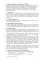
B. RF / Radio Control Board LEDs:
These LEDs are the status indicators for the various states and functions of the Controller
board.
TX (Yellow LED) – This LED indicates that the radio is transmitting.
RX (Green LED) – This LED indicates that the radio is detecting an RF transmission. If
the IP-Link’s radio receiver is subject to RF Interference, this LED will illuminate steady
on and remain on for more than 20 seconds. See page 19 “RF Interference”.
WA (Yellow LED) – A steady on indicates that a radio packet transmission has been
attempted and the controller is waiting for an acknowledgement. Blinking indicates the
RF communication is off the network. Off is a normal indication.
AL (Red LED) – This LED is a status / Troubleshooting indicator. It is currently not in
use and is usually on. This LED can be ignored.
40-7170 Revision 2B July 6, 2012
14
40-7170 Revision 2B July 6, 2012
15
STOP
IF THE 7005I MultiNet Receiver IS NOT CONFIGURED AND ONLINE
READY TO ACCEPT SIGNALS FROM THIS UNIT,
THEN STOP!
Install and configure the MultiNet receiver First!
Then Continue Here
8.0 Programming and Setup of the 7170 IP-Link Transceiver:
NOTICE TO USERS, INSTALLERS, AUTHORITIES HAVING
JURISDICTION, AND OTHER INVOLVED PARTIES
This product incorporates field-programmable software. In order for the product to
comply with the requirements in the Standard for Control Units and Accessories for
Fire Alarm Systems, UL 864, certain programming features or options must be limited
to specific values or not used at all as indicated below.
Program
Feature or Option
Permitted in
UL 864 (Y/N)
TCP/IP Socket timeout
Link Layer
Y
Y
ACK Mode
PinG
Y
Y
Possible functional
settings
12-30
0-254
0/Normal – 1/Quick
Yes / No
Settings permitted in UL 864
12
Primary IP-Link= 1
Secondary IP-Link = 1
Others IP-Links = 1 not higher than 4
Only 1 IP-Link in a Cloud Set to 1/Quick
Yes
To configure the IP-Link Transceiver you communicate with it via the Console Serial
Port. Use a serial terminal program like Telix or Hyper Terminal (included with
Windows) to configure the IP-Link Transceiver. Using this software allows you to send
ASCII character instructions and view the response on the terminal’s display.
The IP-Link Transceiver has a built in 386 DOS computer with 10BASE-T Ethernet Port
incorporated into the system. Configuring the IP-Link Transceiver includes editing data
files that contain ASCII text strings of parameters. Once you have connected to the
Console port with a terminal program you can reset the unit and be presented with an
option to go to a terminal mode where you will get a familiar DOS style prompt.
Commands can be entered at this prompt. An included DOS line editor is used to edit the
configuration files.
40-7170 Revision 2B July 6, 2012
16
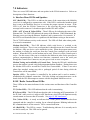
A. Communicating with the 7170 IP-Link Transceiver:
Listed below are instructions for configuring several terminal emulation programs. These
programs can be used to directly communicate with the IP-Link Transceiver via the
Console port to edit essential configuration files.
A.1. Configure Hyper Terminal (in Windows) to communicate with the 7170:
1. In Windows Click on Start, Programs, Accessories, Communications and then
Hyper Terminal.
2. Enter a name and choose an icon for this connection. IP-Link would be a good
choice for a name that you would recognize in the future when needed.
Select an icon for the connection and then select OK.
Figure L – HyperTerminal - Connection Description
40-7170 Revision 2B July 6, 2012
17
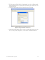
3. Do Not enter any Details for the Country/region, Area code or Phone number.
Instead just pull down the “Connect using” and choose your available free Com
Port and select OK.
4. Under the Connect using select the Com port that you will be using.
Figure M – HyperTerminal - Connect To
5. Under Port Settings change “Bits per second” to 19200. Other settings are “Data
bits:” 8, “Parity:” None, “Stop bits:” 1, “Flow control:” is Hardware then OK.
40-7170 Revision 2B July 6, 2012
18
Figure N – HyperTerminal - COM Properties
6. You are now ready to use HyperTerminal.
Figure O – HyperTerminal
A.2. Optionally, Configure Telix (in DOS) to communicate with the 7170:
1. Locate and start the Telix program. Example: (assuming Telex.exe is in C:\Telix)
CD\Telix<Enter> then Telix<Enter>.
2. Pres <Alt> P to bring up the Com Parameters window.
3. Change communication parameters to 19200,N,8,1,COM<X> where COM<X> is
the COM port you are connected to. Press <F> then <O> to set communication
parameters. Press the number corresponding to the COM Port then press <Enter>
to set Com port and exit parameters window.
40-7170 Revision 2B July 6, 2012
19
4. Press <Alt> T to change or check terminal emulation mode.
(highlight) “ANSI”. Press <Enter> to return to display window.
Next select
B. Initializing the 7170 IP-Link Transceiver:
Once your terminal program is ready (see previous pages), the 7705i MultiNet Receiver
is on-line and your 7170 IP-Link Transceiver is installed and wired, you are ready to
power up the 7170 IP-Link Transceiver and begin the configuration.
1. Confirm that an RS 232 Cable is connected between the serial input of the 7170
“Console” and the COM port of your PC running a terminal program.
2. Confirm that the RJ45 Ethernet Cable is connected between your LAN or WAN
Network and the Ethernet jack on the IP-Link Transceiver.
3. Confirm that the Phone line is connected to the Phone Line jack on the 7170.
4. Connect the Battery in the IP-Link Transceiver.
5. Energize AC Power connected to the IP-Link Transceiver at J2.
6. Once powered up, startup messages should be displayed on your terminal
program screen.
During the startup process and when prompted with:
“Note: For Initial Config Type X then” and before the prompt:
“Type Setup Key…”, press the "X" key to Halt the startup process and access the
Terminal prompt. If the 7170 is already powered, press the Reset button on IPLink Interface board (Middle board) to initialize, then press "X" to get to terminal
prompt.
See Example 1: Startup Messages.
Another option available during startup, shortly after the prompt
“Note: For Initial Config Type X then” and following the prompt
“Type Setup Key…” is to press the “S” key. This will access the Setup Menu,
which will be discussed later in section C.3. An option within the Setup Menu is
to reset the IP-Link, which has up to a 70 second delay.
X = Halt, go to terminal prompt
S = Setup Menu
<No key> = Proceed with Normal Operation
Notes on the Shared Serial Port:
As noted elsewhere in this manual, the Console Port and the Modem share a
single Serial interface. The sharing will not begin until the startup process is
allowed to continue beyond the prompt “Type Setup Key…”. Pressing “X” or
“S” when prompted will interrupt the startup process and the port will be
available for Console use or Setup Menu access respectively. Once past this
point, sharing is occurring. If the Modem LED is on, the serial port is switched to
the modem and any attached terminal program will have no affect. For this
reason, commands sent to the serial port may not get received or cause any
response
If there is no active phone line attached, testing may take an extended period of
time while it tries all possibilities, during which the Console Port will be
unavailable.
40-7170 Revision 2B July 6, 2012
20
If the Port is switched to Console (Modem LED off) then the S<Enter> option
should be available.
40-7170 Revision 2B July 6, 2012
21
RF Interference
If the IP-Link’s radio receiver is subject to RF Interference, the “RX” LED will
illuminate and remain on for more than 20 seconds. The IP-Link should not be
installed in this location until the source of the interference is cleared.
Intermittent on and off of the RX LED is normal operation.
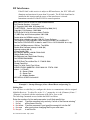
Bios Version 3.3c for uFlashTCP with NE2000 Ethernet
DOC Socket Services - Version 0.2
(C) Copyright 1992-1996, M-Systems Ltd.
TrueFFS-BIOS -- Version 3.3.9 for DiskOnChip 2000 (V4.2)
Copyright (C) M-Systems, 1992-2000
DOS Version 3.3c for JK microsystems Flashlite
(C) HBS Corp and JK microsystems 1991-1999
Packet driver for NE2000, version 11.4.3
Packet driver skeleton copyright 1988-93, Crynwr Software.
This program is freely copyable; source must be available; NO WARRANTY.
See the file COPYING.DOC for details; send FAX to +1-315-268-9201 for a copy.
System: [345]86 processor, ISA bus, Two 8259s
Packet driver software interrupt is 0x60 (96)
Interrupt number 0x9 (9)
I/O port 0x300 (768)
My Ethernet address is 00:90:C2:40:43:9A
Getting Radio Node Time
No Response from Radio Node. Retrying
Got GG59351504230206
Set DOS Date/Time to Mon Dec 11 17:09:53 2006
Closed CommPort
Note: For Initial Config Type X then
UCMD UIPLINK -I00001234 –S192.168.0.101 -P7070 –N101
where -I = IPLinkID
-S = Server IPAddr
-P = Server Port
-N = Modem Number
AES UIPLink UCMD Version 0.02
C:\>
Example 1: Startup Messages (After a Board Reset and pressing X)
Editing files:
You will have to edit file(s) to configure this device to communicate with its assigned
MultiNet Receiver. To edit a file, at the “C:\>” prompt key in “edit {filename}<Enter>”.
{filename} is replaced with the actual name of the file to view or edit.
The following commands are used within the DOS Line Editor:
Enter the number of a line and press enter to edit that specific line.
i: for insert “Use this command only and only if a line of the file was missing”
l: for list
all the lines of the file.
d: for delete “Use this command if you typed the wrong info into the file”
s: for save
after you’re done changing the file you must save.
Q: for quit
to exit the file
40-7170 Revision 2B July 6, 2012
22
C. Configuring the 7170 IP-Link Transceiver:
There is one file that you need to edit in order to configure the 7170 IP-Link Transceiver
to communicate with the components in a system. A Setup Menu discussed later will
allow setting the rest of the RF and TCP/IP configurations. Listed below are instructions
to edit lines within each file that need to be modified. Preceding instructions describe
procedure for getting to the command prompt allowing you to run the Editor, which is
used to edit these files.
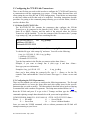
C.1. Edit the WATTCP.CFG file:
The WATTCP.CFG file contains the parameters that configure the IP-Link
Transceiver to be connected to the Internet (LAN/ WAN). The file has 3 entries:
Static IP or DHCP, Gateway and Net mask of the network where the IP-Link
Transceiver will be installed. To view the contents of this file enter at the C prompt
“type wattcp.cfg” and you should see something like this:
my_ip=192.168.0.11
OR
gateway=192.168.0.1.
netmask=255.255.255.0
my_ip=dhcp
Example 2: Contents of the wattcp.cfg file
To edit this file type “edit wattcp.cfg” and enter. You will see the following:
0: my_ip= 192.168.0.11 OR 0: my_ip=dhcp
1: gateway=192.168.0.1
2: netmask=255.255.255.0
Type the line number in the file that you want to replace then <Enter>:
Example, if you want to change line 0 (zero) type 0 and then <Enter>.
Next type your new information:
Examples: 0:my_ip=192.168.1.22
or
0: my_ip=dhcp
Once you’re done editing the wattcp.cfg file, type L + <Enter> to list the file
contents. Then confirm that the 3 lines are correct. Next type S + <Enter> to save and
exit.
C.2. Configuring the TCP/IP parameters:
There are two methods you can use to configure the following parameters. The first and
preferred method is to access the Setup menu and select menu items for the specific
parameter that you wish to modify. The other method, described below involves entering
a command line with a number of arguments. The Setup menu method follows in C.3
Reset the IP-Link and press X to get to the C Prompt, and then type the following
command replacing example data shown below with your actual required data:
UCMD UIPLINK -I00001234 -S192.168.0.101 -P7070 –N978-555-55555<Enter>
Where: -I = IPLinkID
-S = Server IPAddr
-P = Server Port
-N = Server’s Modem Number
Once you enter the UCMD command, with or without parameters the IP-Link will
attempt connecting to your Server.
40-7170 Revision 2B July 6, 2012
23
C.3. Set Up Menu:
There are several methods to access the Setup Menu using a terminal program attached to
the Console port.
•
One is to reset the IP-Link and press “S” following the prompt:
“Type Setup Key within 3 Sec. For Setup Menu”
•
During normal operation, when the Modem is not selected for testing or backup
communication, press “S” plus <Enter>.
Once the Menu is displayed you press a selected highlighted letter and then press
<Enter> to modify its associated parameter(s) or access the function.
Figure P – IP-Link Setup Menu
Functions accessed by pressing I, and Primary Server half of S, T and P are also
configurable using the UCMD command mentioned in C.2.
I: Modifies the 8 digit Hexadecimal IPLinkNode ID of which the last four digits is the
ID reported for this device. It must be unique in the network. This ID is also passed
to the attached RF Board. You must include the leading four zeroes.
R: Resets the IP-Link. There is up to a 70 second delay as the unit waits for the
watchdog program to initiate the reset.
S: Modifies Primary Server IP1 and Backup Server IP2 addresses for the Primary and
Backup (Secondary) MultiNet Receivers.
T: “Server Port1” and “Server Port2” IP port numbers used by the receiver that allows
the IP-Link Transceiver to connect. Default is 7070
P: Modifies the “Primary Modem Server1 Phone#” and “Backup Server2 Phone#”
numbers that the IP-Link Transceiver will call if TCP/IP fails.
The modem feature has not been evaluated by UL.
M: Forces a test of the modem. Same as is automatically run at program start and daily.
D: Displays a scrollable log with the results of the last modem test.
W: Runs tests on the power supply. Follow prompts on display.
40-7170 Revision 2B July 6, 2012
24
U: TCP/IP Socket Timeout is the time that the unit waits for an ACK for a sent TCP/IP
packet. Default is 12. Setting this to greater that 12 seconds will invalidate UL
switch over to Backup Modem of 30 seconds. Contact AES Technical support before
attempting to modify this value. The modem feature has not been evaluated by UL.
L: Set the Linklayer (Link Layer / Level). If the IP-Link Transceiver is one of the two
Local or Remote IP-Links installed to act as the main Primary and Backup units in a
radio cloud of Subscribers, set the Link Layer to 1. If it is in the same radio cloud
with the two IP-Link Transceiver that are set to 1, you may set the Link Layer to 1 or
higher. You must have in an RF region, at least two IP-Links set to Linklayer 1.
None can be set to 0. None should be set higher than 4.
A NetCon 6 or Higher is reported to the Alarm Monitoring System when the
MultiNet Receiver is using Ademco 685 emulation as an “E354 00 C915”
C: This sets the system Cypher (Cipher) Code. This code is also passed to the attached
RF Board and is used to authenticate transmissions by other IntelliNet devices that
must use the came cipher code.
A: Set the RF Acknowledgement / Ack Mode. Use 0 for Quick ACK and 1 for Normal
ACK. Only one IP-Link Transceiver in a radio cloud should be set to 0 for Quick
ACK. Quick ACK means that the IP-Link Transceiver is sending a Packet
Acknowledged Packet on the heels of a reception without listening for a clear
frequency.
Having two IP-Links in the Quick ACK mode could cause Packet Acknowledgments
to be jammed or blocked.
G: PinG - This option when enabled (On), will instruct the IP-Link Transceiver to
Monitor RF traffic and report to the MultiNet receiver if it appears to be lost or silent.
This must be set to Yes for UL installations and NFPA 72 compliance.
Less than 200 seconds after the frequency goes silent (≈150 Seconds), an RF Test is
initiated by the IP-Link to verify its RF operation. This test verifies the RF, IP-Link,
Radio, Coaxial Cable, connectors, surge protectors, Antenna and anything else in the
transmission line, by transmitting a Poll Test. The test is directed to the ID of the last
device for which a transmission was received.
A failure to receive an
Acknowledgement Packet for the transmitted Test, results in the reporting of an RF
failure.
The MultiNet Receiver will generate a code to send to the Alarm Monitoring System
or annunciate the RF Failure. The Ademco 685 emulation code will be “E355 00
C906”. The message indicating that the RF may be lost will be annunciated at the
MultiNet Receiver or transmitted to the Alarm Monitoring System less than 200
seconds after the frequency goes silent.
Q: To Quit menu and return to normal operation.
40-7170 Revision 2B July 6, 2012
25
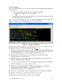
C.4. Test the network connection:
• From a command prompt, reached by pressing X after a reset you can confirm
communication with assigned MultiNet receiver by issuing the command:
ping <MultiNetReceiverIPaddress> and looking for successful transmissions and
replies. Press <Enter> to stop pinging and get a summary result.
• Press reset in preparation for the next step. Similar to below should scroll on the
display of the terminal program.
UCMD UIPLINK -I00001111 -S192.168.0.11 -P7070 –N101
AES UIPLink UCMD Version 0.02
Running UIPLink -v
Setting Watchdog 70 Sec
Calculating UIPLINK.exe Checksum Please Wait... Bytes Read 512Bytes Read 1024By
Done We are UIPLINK.exe with a Chksum of 0xF091, File Size 135040
Press Enter for Menu
UIPLink S0.4.4 Startup ChkSum:F091, Size:135040.
Heart Rate = 5 Seconds
IPlinkID = 00000002
Queued[0], Software Version For Server
Initializing TCP/IP Sockets
My IP Address is 192.168.0.11
sendRequest(TT)
Opening 192.168.0.101 on Port 7070
ServerTime&Date Sync. Thu Jan 06 18:10:46 2005
Radio Node Sent Me:↓
sendQueue
sendRequest(TT)
ServerTime&Date Sync. Thu Jan 06 18:10:46 2005
sendRequest(QQC)
sendRequest(QQF)
Sending Packet[0] to Server1
Unknown Reply from Server <10,00,00,00>
Sending Packet[1] to Server1
ACK Received on Packet[1] from EtherNet Server
sendQueue() done.
My UTC Time = GG46101804060005
IPLinkTime 41DD7F26, NodeTime 41DD7F28
Node Time OK.
Figure Q – IP-Link Serial Port Output at Startup
40-7170 Revision 2B July 6, 2012
26
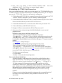
9.0 Testing the 7170 IP-Link Transceiver:
There are several functions of the IP-Link Transceiver that can be tested to confirm
that it is operating properly. Testing is broken up into parts with focus on
increasingly advanced functionality with each part.
A. Test Basic Board Functionality:
The tests in this part are intended to check that there is power to the boards and that
they have at least basic functionality.
Testing RF Board Local operation.
1. After performing a power up or Radio Reset the RX, WA, and AL LEDs will
come on for about one second during the self-test process.
2. Once self-test is complete, the AL LED will come on steady.
Testing Interface Board Local operation.
The board has two LEDs that indicate the status of the Ethernet link. The LNK LED
indicates the status of the Ethernet. When illuminated, the Ethernet Port is receiving
the Ethernet ‘heartbeat’ and is connected to a live network. If this LED is not
illuminated, there is a problem with the Ethernet wiring or the network. The ACT
LED indicates activity on the network. The LED will flash when a data packet is
received or transmitted.
1. If the Ethernet port your IP-Link Transceiver is correctly attached to another
functioning Ethernet port there should be activity on the LNK and/or ACT
LEDs as indicated above.
B. Test Local Board Functionality with terminal:
The tests in this part check the interaction between each board and the attached
terminal.
A terminal connected to the “Serial Input” Port is required to perform testing of the
IP-Link Transceiver at the local installed location. Instructions for connecting and
configuring a terminal to the IP-Link transceiver can be found in Section 8
“Programming and Setup of the 7170 IP-Link”.
Receiving the output on your terminal’s display as shown in “Example 1: Startup
Messages” confirms most of the basic functionality of the IP-Link Transceiver.
Being able to successfully setup the IP-Link Transceiver as discussed in Section 8
confirms functionality and interaction with all the boards.
C. Test RF Signal:
Tests in this part are intended to check the transmission line and components for
proper operation and problems. This is a very important test and should be
performed as soon after power up as feasible. Operating the unit with a faulty
transmission line or component could cause damage to electronics in the unit. As a
precaution, you could disconnect the dB9 connector from the transceiver inside the
IP-Link until this test can be performed.
40-7170 Revision 2B July 6, 2012
27
To test your IP-Link’s RF signal you need to connect a power meter or SWR meter in
the coax line to read power. As with other tests you need a terminal connected to the
“Serial Input” of the IP-Link.
1. With the unit powered, press the Reset button in the IP-Link
2. Type X on the terminal. Should see C:\> prompt.
3. At the C:\> prompt, type IPCOMM<Enter>
4. You will be presented with a menu.
5. Type <Ctrl> + J then two exclamation points “!!” in rapid succession plus
<Enter>. You should now have an AES> prompt.
6. At the AES> prompt, type using upper case, TEST 10. This will key the
transmitter for 10 seconds showing “KEYING TX…” then a timeout or
“DONE.” message at the end.
7. During the 10-second transmission record your meter’s reading.
8. An SWR reading of less than 3 to 1 is acceptable.
9. If the reading is greater than 3 to 1, then replace the antenna, coax and or
coaxial connectors until the reading falls below the acceptable level.
10. <Esc> X
11. Type UCMD<Enter> to restart normal IP-Link functions.
D. Test TCP/IP Communication Functionality:
To test that your TCP/IP configuration works, you can utilize a program called PING,
which is included in the on-board PC. You will want to ping the IP address of the
new gateway that was entered during setup. Type “ping <gateway IP>” and hit enter,
you should get a successful response. If not check your Ethernet connection and with
the IT admin to resolve this issue.
E. Test RF Communication Functionality:
The easiest method to locally test RF functionality is to have a programmed AES
Subscriber unit with 7041 Hand Held Programmer available. Use the “Display
Status” function (<Shft> + <F4>) to determine if your subscriber is connected to the
network and most importantly that “RT1: #### contains the ID of the IP-Link
Transceiver and that the Link Layer (Level) and NETCON are as expected. Level
should be 1 higher than the Link Layer setting in the IP-Link Transceiver.
Contact an operator at the location of the AES Supervising IP-Link Transceiver
Station to confirm that signals are coming in from this IP-Link Transceiver. This test
of course is also confirming TCP/IP communication or complete end-to-end testing as
well.
40-7170 Revision 2B July 6, 2012
28
10.0 Warranty / Service Procedures:
AES CORPORATION
LIMITED PRODUCT WARRANTY AND TECHNOLOGY LICENSE
LIMITED PRODUCT WARRANTY:
AES Corporation (“AES”) warrants to the original purchaser that each AES Subscriber Product will be free from
defects in material and workmanship for three (3) years from date of purchase and all other products purchased from
AES including central station receivers and accessories will be warranted for one (1) year from the date of purchase.
At no cost to the original purchaser for parts or labor, AES will repair or replace any AES Product or any, part or parts
thereof which are judged defective under the terms of this Warranty.
Defective AES Products must be returned to AES directly, provided they are properly packed, postage prepaid. Or
exchange may be made through any authorized direct factory representative for any AES Products that are judged
defective under the terms of this Warranty. Improper or incorrectly performed maintenance or repair voids this
Warranty. This Warranty does not cover replacement parts that are not approved by AES. This Warranty does not
apply to any AES Product or any part thereof that has been altered in any way to affect its stability or reliability, or that
has been subjected to abuse, misuse, negligence, accident or act of God, or that has had the serial number effaced or
removed.
Certain AES Products are designed to operate and communicate with other specified AES Products and certain other
specified products, systems or networks authorized or approved by AES, as identified in the applicable AES Product
instructions. This Warranty does not apply to any AES Product that is used with any unauthorized or unapproved
products, systems or networks, or that has been installed, applied or used in any manner, other than in strict accordance
with AES instructions.
AES makes no warranty, express or implied, other than what is expressly stated in this Warranty. If the law of your
state provides that an implied warranty of merchantability, or an implied warranty of fitness for particular purpose, or
any other implied warranty, applies to AES, then any such implied warranty is limited to the duration of this Warranty.
AES cannot be aware of and is not responsible for the differing values of any property to be protected by its alarm
reporting systems. This Warranty does not cover and AES shall not be liable for any defect, incidental or
consequential, loss or damage arising out of the failure of any AES Product to operate.
Some states do not allow the exclusion or limitation of the durations of implied warranties or the limitation on
incidental or consequential damages, so the above limitations or exclusions may not apply to you.
This Warranty gives you specific legal rights and you may also have other rights that vary from state to state.
TECHNOLOGY LICENSE:
Certain AES Products include software, protocols and other proprietary and confidential technology and trade secrets
of AES, which are incorporated in or provided, with AES Products solely for use in conjunction with and in order to
operate AES Products (“Licensed Technology”). AES grants the original purchaser a non-exclusive license to use
such Licensed Technology solely in connection with the use and operation of AES Products and for no other purpose
or use whatsoever. No title or ownership in or to any such Licensed Technology is conveyed by the sale or delivery of
any AES Products; all such rights are retained by AES.
AES SERVICE PROCEDURE: Contact AES at (978) 535-7310, [fax (978) 535-7313] to receive a Return
Authorization Number. Have the AES part number and serial number ready. Repack equipment in original or
equivalent packaging. Inside the box, please include a contact name, telephone number, address and a brief description
of the reason for return.
Ship authorized RA items freight-prepaid to:
(call for Return Authorization number)
Repair Services, RA#________________
AES Corporation
285 Newbury Street
Peabody, MA 01960 USA
Warranty Rev date 5/08/06
40-7170 Revision 2B July 6, 2012
29