1
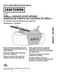
Owner's Manual/Manual
Del Propietario
I:RRFTSMR
315MM= GARAGE DOOR OPENER
ABRIDOR DE PUERTA DE COCHERA 315MN_,
For Residential
Use Only/Solo
Model/Modelo
para uso residencial
139.53918D
m
G3
m
Z_
O
Read and follow all safety rules
and operating instructions before
first use of this product.
Leer y seguir todas las reglas de
seguridad y las instrucciones de
operacion antes de usar este
producto por primera vez.
Fasten the manual near the garage
door after installation.
Guardar este manual cerca de la
puerta de la cochera.
Periodic checks of the opener are
required to ensure safe operation.
Se deben realizar revisiones
periodicas del abridor de puertas
para asegurar su operacion
segura.
Sears, Roebuck
and Co., Hoffman
www.sears.com/craftsman
Estates,
IL 60179
U.S.A
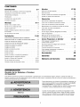
TABLE
OF CONTENTS
Introduction
2.7
Adjustment
27-29
Safety symbol review and signal word review .........
2
Program the travel limits
Preparing your garage door .......................
Tools needed ..................................
3
3
Setting the force .............................
Planning
....................................
Carton inventory
4-5
...............................
Hardware inventory
.............................
Assembly
......................
28
Test the safety reversal system .................
29
Test The Protector System ®(safety sensors)
6
Operation
7
Operation safety instructions
8.11
27
......
29
30-36
...................
30
Using your garage door opener .................
30
31
Assemble the rail and install the trolley ..............
Fasten the rail to the motor unit ...................
8
9
Using the wall-mounted
Care of your opener ..........................
32
Install the idler pulley ............................
9
To open the door manually
32
Install the belt and attach the belt cap retainer .......
Set the tension ................................
Installation
10
11
11-26
Installation safety instructions ....................
Determine the header bracket location .............
11
12
Install the header bracket
13
.......................
Attach the rail to the header bracket ...............
Position the opener
14
............................
15
Hang the opener ..............................
Install the control console .......................
16
17
Install the battery ..............................
18
Install the lights ...............................
18
Attach the emergency release rope and handle ......
18
Electrical requirements
19
.........................
Install The Protector System ®(safety sensors)
Fasten the door bracket ......................
Connect the door arm to the trolley .............
.... 20-22
23-24
25-26
control console
..........
....................
Battery backup ..............................
Having a problem (Troubleshooting)
33
.............
34
Diagnostic chart .............................
35
LCD motion detecting control
console messages ...........................
36
Programming
37.38
To add or reprogram a hand-held remote control
To erase all codes from motor unit memory
3-Function remotes ..........................
.......
To add, reprogram or change a
Keyless Entry PIN ...........................
Repair
...37
37
37
38
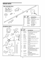
Parts
39-40
Rail assembly parts ..........................
39
Installation parts .............................
39
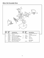
Motor unit assembly parts .....................
40
Accessories
41
Warran
ty
41
Repair
Parts
& Service
Back
Cover
INTRODUCTION
Safety
Symbol
Review
and Signal
Word Review
This garage door opener has been designed and tested to offer safe service provided it is installed, operated,
maintained and tested in strict accordance with the instructions and warnings contained in this manual.
Mechanical
When you see these Safety Symbols and Signal Words
on the following pages, they will alert you to the
possibility of serious injury or death if you do not
comply with the warnings that accompany them. The
hazard may come from something mechanical or from
electric shock. Read the warnings carefully.
Electrical
When you see this Signal Word on the following pages, it
will alert you to the possibility of damage to your garage
door and/or the garage door opener if you do not comply
with the cautionary statements that accompany it. Read
them carefully.
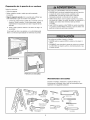
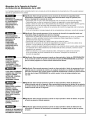
Preparing
your
garage
door
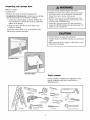
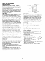
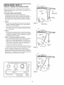
Before you begin:
• Disable locks.
To prevent possible SERIOUSINJURYOR DEATH:
• ALWAYScall a trained door systems technician if garage
door binds, sticks, or is out of balance An unbalanced
garage door may not reverse when required
• NEVERtry to loosen, move or adjust garage door, door
springs, cables, pulleys, brackets or their hardware, all of
which are under EXTREMEtension
• Remove any ropes connected to garage door.
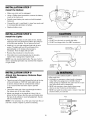
• Complete the following test to make sure your garage
door is balanced and is not sticking or binding:
1. Lift the door about halfway as shown. Release the
door. If balanced, it should stay in place, supported
entirely by its springs.
• Disable ALL locks and remove ALL ropes connected to
garage door BEFOREinstalling and operating garage door
opener to avoid entanglement.
2. Raise and lower the door to see if there is any
binding or sticking.
If your door binds, sticks, or is out of balance, call a
trained door systems technician.
To prevent damageto garage door and opener:
• ALWAYSdisable locks BEFOREinstalling and operating the
opener
• ONLYoperategarage door opener at 120V, 60 Hz to avoid
malfunction and damage
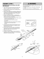
Sectional Door
One-Piece Door
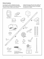
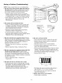
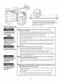
Tools
needed
During assembly, installation and adjustment of the
opener, instructions will call for hand tools as
illustrated below.
Pencil
Level (Optional)
Hack Saw
Tape Measure
Wire Cutters
Claw Hammer
Drill
Stepladder
3/16"
5/16"Bits
and
5/32" Drill
ts
Scre wd rive r
Adjustable
End Wrench
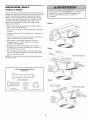
Do you have an access door in addition to the garage
door? If not, Model 139.53702 Emergency Key
Release is required. See Accessories page.
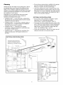
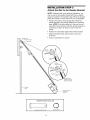
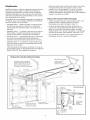
Planning
Identify the type and height of your garage door. Survey
your garage area to see if any of the conditions below
apply to your installation. Additional materials may be
required. You may find it helpful to refer back to this page
and the accompanying illustrations as you proceed with
the installation of your opener.
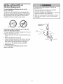
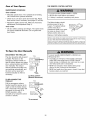
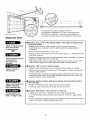
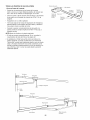
Look at the garage door where it meets the floor. Any
gap between the floor and the bottom of the door must
not exceed 1/4" (6 mm). Otherwise, the safety reversal
system may not work properly. See Adjustment Step 3.
Floor or door should be repaired.
Depending on your requirements, there are several
installation steps which may call for materials or
hardware not included in the carton.
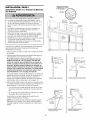
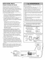
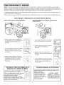
SECTIONAL DOOR INSTALLATIONS
• Installation Step 1 - Look at the wall or ceiling above
the garage door. The header bracket must be securely
fastened to structural supports.
• Do you have a steel, aluminum, fiberglass or glass
panel door? If so, horizontal and vertical
reinforcement is required (Installation Step 12).
• Installation Step 5 - Do you have a finished ceiling in
your garage? If so, a support bracket and additional
fastening hardware may be required.
• The opener should be installed above the center of the
door. If there is a torsion spring or center bearing plate
in the way of the header bracket, it may be installed
within 4 feet (1.22 m) to the left or right of the door
center. See Installation Steps 1 and 12.
• Installation Step 11 - Depending upon garage
construction, extension brackets or wood blocks may
be needed to install sensors.
• Installation Step 11 -Alternate floor mounting of the
safety reversing sensor will require hardware not
provided.
• If your door is more than 7 feet (2.13 m) high, see rail
extension kits listed on Accessories page.
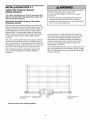
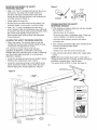
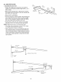
SECTIONAL DOOR INSTALLATION
FINISHED
CEILING
/
Support bracket &
fastening hardware
is required.
See page 16.
Horizontal and vertical reinforcement
is needed for lightweight garage doors
(fiberglass, steel, aluminum, door with
glass panels, etc.). See page 23 for details.
Rail
\
\
\
Header Wall
i
Extension
OR
Torsion Spring
Wallmounted
Door
Control
Centerline
I
iof Garage
I i
Door
j _I
Spring.
Door
I
......
!
_!
O
CLOSED
Header
Bracket
Gap between floor
and bottom of door
Safety Reversing
Sensor
Trolley
Stop Bolt
Garage
Door
Spring
Safety
Reversing
Sensor
POSITION
Trolley
Belt
must not exceed 1/4" (6 mm).
Emergency Release
Rope & Handle
eader
fall
arage
oor
Door
Bracket
Curved
Door
Arm
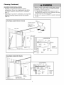
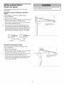
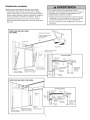
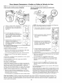
Planning
(Continued)
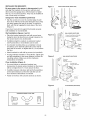
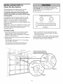
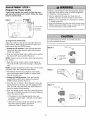
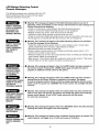
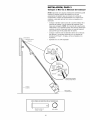
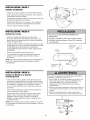
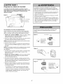
ONE-PIECE DOOR INSTALLATIONS
Without a properly working safety reversal system, persons
(particularly small children) could be SERIOUSLYINJURED
or KILLED by a closing garage door.
• The gap between the bottom of the garage door and the
floor MUST NOTexceed 1/4" (6 mm). Otherwise, the safety
reversal system may not work properly.
• The floor or the garage door MUST be repairedto eliminate
the gap.
• Generally, a one-piece door does not require
reinforcement. If your door is lightweight, refer to the
information relating to sectional doors in Installation
Step 12.
• Depending on your door's construction, you may need
additional mounting hardware for the door bracket
(Step 12).
ONE-PIECE DOOR WITHOUT TRACK
FINISHED
& fastening
hardware is required.
See page t6,
_-'_
Header Wall
I
Rail
Motor Unit
Wall-mounted
Door Control
/
Access
Door
CLOSED
POSITION
Trolley Stop Bolt
Belt
drt1 I
Safety Reversing
Sensor
Safety Reversing Sensor
Trolley
i
Emergency
Release
Rope & Handle
i
Gap between floor
and bottom of door must not exceed 1/4" (6 mm).
Straight
Door
Arm
_eader
Vail
Door
Arm
Garage
Door
ONE-PIECE DOOR WITH TRACK
CLOSED
Trolley
Header
POSff[ON
Stop Bolt
Belt
I
S'_-Head_r
idh,.
_////'_
"//A
///'A-_/I
let
Reversing
Sensor
i
Safety
Reversing
Sensor
Gap between floor
and bottom of door
must not exceed 1/4" (6 ram),
Door Arm _j°°°°°°1°°°°°)_
Door
I
Bracket
Garage
Door
--
Curved
Bracket
Wall
Trolley
Straight
Door
Arm
Rail
/
--
Emergency
Release
Rope &
Handle
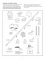
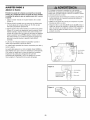
Carton
Inventory
Your garage door opener is packaged in one carton
which contains the motor unit and all parts illustrated
below. Accessories will depend on the model purchased.
If anything is missing, carefully check the packing
;
Z:z
:b
:::?b- -_
,%
material. Parts may be stuck in the foam. Hardware for
assembly and installation is shown on the next page.
Save the carton and packing material until installation
and adjustment is complete.
i a!
._ ,,,
SECURITY÷ ®
3-Function Remote Control (2)
Battery
Motion Detecting
Control Console (LCD)
Belt Cap Retainer
Trolley
SECURITY+ ®
Keyless Entry
Rail
Center/Back
Sections
Motor Unit with 2 Light Lenses
Idler Pulley
Hanging Brackets
Belt
Rail
Fron! (header)
/_¢v2
Curved Door
Arm Section
Header Bracket
Door Bracket
2-Conductor Bell Wire
White & White/Red
Safety Reversing
Sensor Bracket (2)
The Protector System _
(2) Safety Reversing Sensors
(1 Sending Eye and 1 Receiving Eye)
with 2-Conductor White & White/Black
Bell Wire attached
Safety Labels
and
Literature
Straight Door
Arm Section
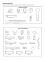
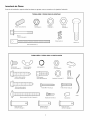
Hardware
Inventory
Separate all hardware and group as shown below for the assembly and installation procedures.
ASSEMB_
HARDWARE
©
Spring/Trolley
Nut (1)
Lock Nut
1/4"-20 (2)
Lock Washer
3/8" (1)
Nut
3/8" (1)
i
Bolt 1/4"-20x 1-3/4" ( 1)
S5
F
Master
Link (2)
Trolley Threaded
Idler Bolt (1)
Shaft (1)
INSTALLATION HARDWARE
O
Carriage Bolt
1/4"-20xl/2" (2)
Wing Nut
1/4"-20 (2)
©
Ring
Fastener (3)
©
llllllll[_
Hex Bolt
5/16"-18x7/8"
Lag Screw
5/16"-9xl -5/8" (2)
(4)
Screw
6ABx1-1/4"
Lag Screw
5/16"-18xl -7/8" (2)
Handle
Nut 5/16"-18 (6)
Lock Washer
5/16" (7)
(2)
Insulated
Staples (30)
Screw 6-32xl"
(2)
Rope
Carriage Bolt
5/16"-18x2-1/2"
(2)
Drywall Anchors (2)
o] I_
o]
Clevis Pin
5/16"x1-1/2"
(1)
Spacer (2)
Clevis Pin
5/16"x1" (1)
o_
Clevis Pin
5/16"x1-1/4"
(1)
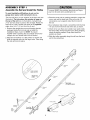
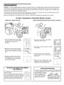
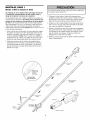
ASSEMBLY
Assemble
STEP
1
the Rail and Install
the Trolley
To prevent INJURYfrom pinching, keep hands and fingers
away from the joints while assembling the rail.
To avoid installation difficulties, do not run the
garage door opener until instructed to do so.
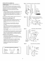
The front rail has a cut out "window"at the door end (see
illustration). The hole above this window is larger on
the top of the rail than on the bottom. A smaller hole
3-1/2" (8.9 cm) away is close to the rail edge. Rotate the
back rail so it has a similar hole close to the opposite
edge, about 4-3/4" (12 cm) from the far end.
3. Place the motor unit on packing material to protect the
cover, and rest the back end of the rail on top. For
convenience, put a support under the front end of
the rail.
1. Remove the straight door arm and hanging bracket
packaged inside the front rail and set aside for
Installation Steps 5 and 12. NOTE: To prevent
INJURY while unpacking the rail carefully remove the
straight door arm stored within the rail section.
5. Check to be sure there are 4 plastic wear pads inside
the inner trolley. If they became loose during shipping,
check all packing material. Snap them back into
position as shown.
2. Align the rail sections on a flat surface as shown and
slide the tapered ends into the larger ones. Tabs along
the side will lock into place.
4. As a temporary stop, insert a screwdriver into the hole
10" (25 cm) from the front end of the rail, as shown.
6. Slide the trolley assembly along the rail from the back
end to the screwdriver.
Trolley
End
9ered
End
Rails
(TO MOTOR UNIT)
)ered
End
,ered
End
Screwdriver
Tabs
Windo_
Cut-Out
Idler
Pulle
Front Rail I
(TO DOOR)
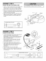
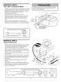
ASSEMBLY
Fasten
the
STEP
Rail
2
to the
Motor
Unit
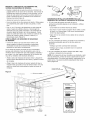
To avoid SERIOUSdamageto garage door opener, use ONLY
those bolts/fasteners mounted in the top of the opener.
• Insert a 1/4"-20xl -3/4 bolt into the cover protection bolt
hole on the back end of the rail as shown. Tighten
securely with a 1/4"-20 lock nut. Do NOTovertighten.
• Remove the two bolts from the top of the motor unit.
• Place the "U" bracket, flat side down, on the motor unit
and align the bracket holes with the bolt holes. Fasten
with the )reviously removed bolts.
Bolts _
• Align the rail assembly with the top of the motor unit.
Slide the rail end onto the "U" bracket, all the way to
the stops that protrude on the top and sides of the
brackeL
Motor Unit
Belt Pulley
:
"U" Bracket
Bolt
Cover
Protection
Bolt Hole _
HARDWARE
SHOWN ACTUAL SIZE
SLIDE RAIL TO STOPS
ON TOP AND SIDES
OF BRACKET
I
Lock Nut
Lock Nut
1/4"-20
Bolt 1/4"-20x1-3/4"
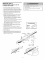
ASSEMBLY
Install
the
STEP
Idler
3
Pulley
• Lay the belt beside the rail, as shown. Grasp the end
with the hooked trolley connector and pass
approximately 12" (30 cm) of belt through the window.
Keep the ribbed side toward the rail, and allow it to
hang until Assembly Step 5.
• Remove the tape from the idler pulley. The inside
center should be pre-greased. If dry, regrease to
ensure proper operation.
Bolt
• Place the idler pulley into the window as shown.
• Insert the idler bolt from the top through the rail and
pulley. Tighten with a 3/8" lock washer and nut
underneath the rail until the lock washer is
compressed.
• Rotate the pulley to be sure it spins freely.
Trolley
Grease
-.
Idler Bolt
Pulley
'\\
U
__
_
Lock Washer
3/8"
• Insert a 1/4"-20xl-3/4 bolt into the trolley stop hole in
the front of the rail as shown. Tighten securely with a
1/4"-20 lock nut.
HARDWARE
_/side
Stop Hole _p
\\
| |
Trolley
Connector
SHOWN ACTUAL
Bolt 1/4"-20xl-3/4"
Idler _..
Pulley i
Lock
Nut
SIZE
Lock Nut 1/4"-20
Nut 3/8"
Lock Washer 3/8"
ASSEMBLY
STEP
Install
the Belt
Cap Retainer
and
4
Attach
the
Belt
To avoid possible SERIOUSINJURYto fingers from moving
garage door opener:
• ALWAYSkeep hand clear of belt pulley while operating
opener•
• Securely attach belt pulley cover BEFOREoperating.
1. Pull the belt around the idler pulley and toward the
trolley. The ribbed side must contact the pulley,
2. Hook the trolley connector into the retaining slot on
the trolley as shown.
3. With the trolley against the screwdriver, dispense the
remainder of the belt along the rail length toward the
motor unit and around the sprocket. The sprocket
teeth must engage the belt.
4. Check to make sure the belt is not twisted, then
connect it to the flat end of the trolley threaded shaft
with the master link, as illustrated:
• Push pins of master link bar through holes in end of
belt and trolley threaded shaft.
• Push master link cap over pins and past
pin notches.
HARDWARE
SHOWN
ACTUAL
S_ZE
• Slide clip-on spring over cap and onto pin notches
until both pins are securely locked
in place.
Hex Screw 8x3/8"
5. Insert the trolley threaded shaft through the hole in
the trolley. Be sure the belt is not twisted, and the
ribbed side faces the rail.
Spring/Trolley
6. Hold the belt at the trolley shaft as you thread the
spring nut by hand onto the shaft until finger tight
•
the trolley, Do not use any tools.
against
/
M,aster
Link.
bllp-un
8. Position the belt cap retainer over the motor• unit
sprocket as shown and fasten to the mounting plate
with 8x3/8" hex screws provided.
bprlng
Master
_
_z_
_'_._
/
/_/.,_pv_*.-
Link Cap _....<'<_-._/jy._
->_._
J_J_
__'_'"-'._'<,_,
"
___,_/"
___)
Pin
Trolley
Threaded
Sh t
__r_'_fO
,y
__'_"
I
f
_/
__
7. Remove the screwdriver.
_
Nut
Master
Link Bar
Round
Retaining
Oonnee,or
Idler Pulley
I
Belt Cap_
' I
Hex Screws
#8x3/8"
Retainer
Motor
Unit
Belt Pulley
Plate
10
ASSEMBLY
STEP
5
Set the Tension
• Insert a screwdriver tip into one of the nut ring slots
and brace it firmly against the trolley.
S
• Place a 7/16" open end wrench on the square end.
Rotate the nut about 1/4 turn until the spring releases
and snaps the nut ring against the trolley.
j
This sets the spring to optimum belt tension.
You have now finished assembling your garage door
opener. Please read the following warnings before
proceeding to the installation section.
Trolley
Square
End
Nut Rin(
Nut Ring
I AFTERRE'EASE
(2.5 cm)
1-1/4"
(3.18 cm)
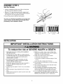
INSTALLATION
IMPORTANT INSTALLATION INSTRUCTIONS
To reduce the risk of SEVERE INJURY or DEATH:
1. READAND FOLLOWALL INSTALLATIONWARNINGS
AND INSTRUCTIONS.
8. NEVERwear watches, rings or loose clothing while
installing or servicing opener.They could be caught in
garage door or opener mechanisms.
9. Install wall-mounted garage control console:
• within sight of the garage door.
• out of reachof children at minimum height of 5 feet
(1.5 m).
• away from ALL moving parts of the door.
10. Place entrapment warning label on wall next to garage
control console.
2. Install garage door opener ONLYon properly balanced
and lubricated garage door. An improperly balanced door
may not reverse when required and could result in
SEVEREINJURYor DEATH.
3. ALL repairs to cables, spring assemblies and other
hardware MUST be made by a trained door systems
technician BEFOREinstalling opener.
4. Disable ALL locks and remove ALL ropes connected to
garage door BEFOREinstalling opener to avoid
entanglement.
5. Install garage door opener 7 feet (2.1 m) or more above
floor.
11. Place manual release/safetyreverse test label in plain
view on inside of garage door.
12. Upon completion of installation, test safety reversal
system. Door MUST reverse on contact with a 1-1/2"
(3.8 cm) high object (or a 2x4 laid flat) on the floor.
13. To avoid SERIOUSPERSONALINJURY or DEATHfrom
electrocution, disconnect ALL electric and battery power
BEFOREperforming ANYservice or maintenance.
6. Mount emergency releasehandle 6 feet (1.8 m) above
floor.
7. NEVERconnect garage door opener to power source until
instructed to do so.
11
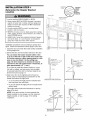
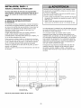
INSTALLATION
Determine
Location
the
STEP
Header
1
Bracket
Ceiling
q
Unfinished
CEILINGOPTIONALHEADERFORMOUN
2x4_
Header Wall
Vertical Centerline
of Garage Door
To prevent possible SERIOUSINJURYor DEATH:
• Header bracket MUST be RIGIDLYfastened to structural
support on header wall or ceiling, otherwise garage door
might not reverse when required. DO NOTinstall header
bracket over drywall.
• Concreteanchors MUST be used if mounting header
bracket or 2x4 into masonry.
• NEVERtry to loosen, move or adjust garage door, springs,
cables, pulleys, brackets, or their hardware, all of which are
under EXTREMEtension.
2x4
/'
Structural
Supports
• ALWAYScall a trained door systems technician if garage
door binds, sticks, or is out of balance. An unbalanced
garage door might not reverse when required.
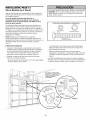
Installation procedures vary according to garage door
types. Follow the instructions which apply to your door.
1. Close the door and mark the inside vertical centerline
of the garage door.
2. Extend the line onto the header wall above the door.
F
You can fasten the header bracket within 4 feet
(1.22 m) of the left or right of the door center only
if a torsion spring or center bearing plate is in the
way; or you can attach it to the ceiling (see
page 13) when clearance is minimal. (It may be
mounted on the wall upside down if necessary, to
gain approximately
1/2" (1 cm).)
_*=T_L_2"(5 crn)
Header Wall
Highest
Track
_L
of Travel
If you need to install the header bracket on a 2x4
(on wall or ceiling), use lag screws (not provided)
to securely fasten the 2x4 to structural supports as
shown here and on page 13.
_=="T_,
(5 cm)
Header 2"Wall
Track
Point
_nt
Y
Door
of Travel
3. Open your door to the highest point of travel as
shown. Draw an intersecting horizontal line on the
header wall above the high point:
Sectional
door with curved track
One-piece
door with horizontal
track
• 2" (5 cm) above the high point for sectional door
and one-piece door with track.
• 8" (20 cm) above the high point for one-piece door
without track.
This height will provide travel clearance for the top
edge of the door.
NOTE: If the total number of inches exceeds the
height available in your garage, use the maximum
height possible, or refer to page 13 for ceiling
installation.
_Wall
DOlOr
_
_Hardw,are
Hight st
i i_
of Travel
One-piece door without track:
jamb hardware
12
One-piece door without track:
pivot hardware
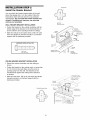
INSTALLATION
Install
the
Header
STEP
2
Wall Mount
Bracket
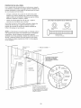
You can attach the header bracket either
above the garage door, or to the ceiling.
instructions which will work best for your
requirements. Do not install the header
drywall. If installing into masonry, use
anchors (not provided).
to the wall
Follow the
particular
bracket over
concrete
Optional
Mounting
WALL HEADER BRACKET INSTALLATION
• Center the bracket on the vertical centerline with the
bottom edge of the bracket on the horizontal line as
shown (with the arrow pointing toward the ceiling).
-
• Mark the vertical set of bracket holes. Drill 3/16" pilot
holes and fasten the bracket securely to a structural
support with the hardware provided.
Holes
Vertical
Centerline
e Door
Header
Wall-
Lag Screws
5/16"x9x1-5/8"
2x4
Structural
Support
Spring
HARDWARE
SHOWN
ACTUAL
SIZE
Horizontal
Line
.-" /
J
111111111
i
Lag Screw
Highest Point of
Garage Door Travel
5/16"-9xl
-5/8"
--
Garage
Door-
Centerline
of Garage Door
CEILING HEADER BRACKET INSTALLATION
• Extend the vertical centerline onto the ceiling as
shown.
• Center the bracket on the vertical mark, no more than
6" (15 cm) from the wall. Make sure the arrow is
pointing away from the wall. The bracket can be
mounted flush against the ceiling when clearance
is minimal.
__
• Mark the side holes. Drill 3/16" pilot holes and fasten
bracket securely to a structural support with the
hardware provided.
-- Finished
/_
__ __ _
_
/ _ __
Ceiling
--
Vertical Centerline
of Garage Door
Header
Bracket
/_
6" (15 cm) Maximum
Ceiling Mounting
Holes
Door
Spring
"
Lag Screws
5/16"x9x1-5/8"
-- Header Wall --
Centerline
of Garage Door
13
INSTALLATION
Attach
the
Rail
STEP
to the
3
Header
Bracket
NOTE: (Optional) With some existing installations, you
may re-use the old header bracket with the two plastic
spacers included in the hardware bag. Place the spacers
inside the bracket on each side of the rail, as illustrated.
• Position the opener on the garage floor below the
header bracket. Use packing material as a protective
base. NOTE: If the door spring is in the way, you will
need help. Have someone hold the opener securely on
a temporary support to allow the rail to clear the
spring.
• Position the rail bracket against the header bracket.
• Align the bracket holes and join with a clevis pin
as shown.
• Insert a ring fastener to secure.
//
//
//
//
//
0
\
\
\
Mounting
Hole
Existing
Header Bracket
Existing
Clevis Pin
0
Spacer
Hole
)PTION W[TH
SOME EXISTING
INSTALLATIONS
Garage
Door
Opener Carton or
Temporary
Support
HARDWARE
SHOWN ACTUAL
SIZE
oH @
C{evie
Pin 5/16"xl
-1/2"
14
Ring Fastener
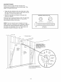
INSTALLATION
Position
the
STEP
4
Opener
To prevent damageto garage door, rest garage door opener
rail on 2x4 placed on top section of door.
Follow instructions which apply to your door type
as illustrated.
SECTIONAL
TRACK
DOOR OR ONE-PIECE DOOR WITH
A 2x4 laid flat is convenient for setting an ideal
door-to-rail distance.
• Remove foam packaging.
• Raise the opener onto a stepladder. You will need help
at this point if the ladder is not tall enough.
• Open the door all the way and place a 2x4 laid flat on
the top section beneath the rail.
• If the top section or panel hits the trolley when you
raise the door, pull down on the trolley release arm
to disconnect inner and outer sections. Slide the outer
trolley toward the motor unit. The trolley can remain
disconnected until Installation Step 12 is completed.
Iley
ReleaseArm
ENGAGED
_
I
RELEASED _d
ONE-PIECE DOOR WlTHOUTTRACK
A 2x4 on its side is convenient for setting an ideal
door-to-rail distance.
H
Reader
i'
• Remove foam packaging.
• Raise the opener onto a stepladder. You will need help
at this point if the ladder is not tall enough.
• Open the door all the way and place a 2x4 on its side
on the top section of the door beneath the rail.
L_
• The top of the door should be level with the top of the
motor unit. Do not position the opener more than 4"
(10 cm) above this point.
15
2X4 is used to determine
the correct mounting height
from ceiling.
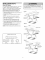
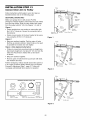
INSTALLATION
Hang
the
STEP
5
Opener
To avoid possible SERIOUSINJURYfrom a falling garage
door opener, fasten it SECURELYto structural supports of
the garage. Concreteanchors MUST be used if installing any
brackets into masonry.
Three representative installations are shown. Yours may
be different. Hanging brackets should be angled
(Figure 1) to provide rigid support. On finished ceilings
(Figures 2 and 3), attach a sturdy metal bracket to
structural supports before installing the opener. This
bracket and fastening hardware are not provided.
1. Measure the distance from each side of the motor unit
to the structural support.
Figure 1
r' Supports
2. Cut both pieces of the hanging bracket to required
lengths.
Measure
Distance
3. Drill 3/16" pilot holes in the structural supports.
',
Lag Screws
5/16"-18xl -7/8"
\
4. Attach one end of each bracket to a support with
5/16"-18xl -7/8" lag screws.
Bolt 5/16"-18x7/8"
Lock Washer 5/16"
Nut 5/16"-18
',
5. Fasten the opener to the hanging brackets with
5/16"-18x7/8" hex bolts, lock washers and nuts.
6. Check to make sure the rail is centered over the door
(or in line with the header bracket if the bracket is not
centered above the door).
Figure 2
7. Remove the 2x4. Operate the door manually. If the
door hits the rail, raise the header bracket.
Hidden
NOTE: DO NOT connect power to opener at this time.
Bracket
(Not Provided)
_ __ _
Support
_ _ ....
_
_
_
_ _ __
--_t_
_
Lag Screws
5/16"-18xl-7/8"
FINISHED CEILING
_J
(Not Provided)
Bolt 5/16"-18x7/8"
_
HARDWARE
SHOWN
ACTUAL
Lock Washer
Nut 5/16"-18
5/16"
Bolt 5/16"-18x7/8"
Lock Washer 5/16"
Nut 5/16"-18
SIZE
Figure 3
5/16"-18xl
Lag Screws -7/8"
Bolt 5/16"-18x7/8"
16
__ _
"_\
__ _
_ _-
,/js/
Nut 5/16"-18
INSTALLATION
Install
the
STEP
Control
6
Console
To prevent possible SERIOUSINJURYor DEATHfrom
electrocution:
Locate control console within sight of door, at a minimum
height of 5 feet (1.5 m) where small children cannot
reach, away from moving parts of door and door
hardware. If installing into drywall, drill 5/32" holes and
use the anchors provided. For pre-wired installations
(as in new home construction), it may be mounted to a
single gang box (Figure 2).
• Disconnect ALL electric and battery power BEFORE
performing ANY service or maintenance.
• Connect ONLYto 24 VOLTlow voltage wires.
To prevent possible SERIOUSINJURYor DEATHfrom a
closing garage door:
• Install control console within sight of garage door, out of
reach of children at a minimum height of 5 feet (1.5 m), and
away from ALL moving parts of door.
• NEVERpermit children to operate or play with control
console push buttons or remote controls.
• Activate door ONLYwhen it can be seen clearly, is properly
adjusted, and there are no obstructions to door travel.
• ALWAYSkeepgarage door in sight until completely closed.
NEVERpermit anyoneto cross path of closing garage door.
1 .Strip 7/16" (11 mm) of insulation from one end of bell
wire and connect to the two screw terminals on back of
control console by color: white wire to 2 and white/red
wire to the 1.
2. Remove cover by gently prying at slot in top of the
cover with a small flat head screwdriver. Fasten with
6ABx1-1/4" self-tapping screws (drywall installation) or
6-32x1" machine screws (into gang box) as follows:
• Install bottom screw, allowing 1/8" (3 mm) to protrude
above wall surface.
Outside Keylock Accessory Connections
To opener quick-connect terminals: white to white;
white/red to red.
• Position bottom of control console on screw head
and slide down to secure. Adjust screw for snug fit.
• Drill and install top screw with care to avoid cracking
plastic housing. Do not overtighten.
HARDWARE
SHOWN
ACTUAL SIZE
• Insert top tabs and snap on cover.
3. (For standard installation only)
and across ceiling to motor unit.
to secure wire in several places.
with a staple, creating a short or
Run bell wire up wall
Use insulated staples
Do not pierce wire
open circuit.
4. Strip 7/16" (11 mm) of insulation from end of bell wire.
Connect bell wire to the quick-connect terminals as
follows: white to white and white/red to red.
Control Panel (pre-wired)
REMOVE & REPLACE
6. Use tacks or staples to permanently attach entrapment
warning label to wall near control console, and manual
release/safety reverse test label in a prominent
location on inside of garage door.
Bell
Wire II
_.
II
Figure 2
Control Console Connections
To release wire, push in
tab with screwdriver tip
Strip wire 7/16" (11 mm)
Screws
I _,_-L-.__N'-m£i
i Bottom
'
(BACK VIEW)
INSTALLATION
24 Volt Bell Wire
_JA-_--Terminal
il
PRE-WIRED
Ta__lnsert
Top
Push Bar Cover
+11 *')Mounting
I :1 Hole
14 '
COVER
To Replace
NOTE: DO NOT connect power and operate opener at
this time. The trolley will travel to the full open position
but will not return to the close position until the sensor
beam is connected and properly aligned.
--
Drywall Anchors
Figure 1
5. Position the antenna wire as shown.
_Top
(_ I+
II
Insulated
Staples
Control Panel (std installation)
Mounting
Hole
Red White Grey
17
INSTALLATION
Install
the
STEP
7
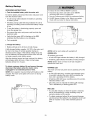
Battery
Battery
• Make sure motor unit is unplugged.
• Using a Phillips head screwdriver, remove the battery
cover on the motor unit.
• Partially insert battery into motor unit with terminals
facing out.
• Connect the red (+) and black (-) wires from motor unit
to corresponding terminals on battery.
• Replace battery cover.
INSTALLATION
Install
the
STEP
8
Lights
To prevent possible OVERHEATINGof the endpanel or light
socket:
• Press the release tabs on both sides of lens. Gently
rotate lens back and downward until the lens hinge is
in the fully open position. Do not remove the lens.
• DO NOTuse short neck or specialty light bulbs.
• DO NOTuse halogen bulbs. Use ONLYincandescent.
• Install up to a 100 watt maximum light bulb in each
socket. The lights will turn ON and remain lit for
approximately 4-1/2 minutes when power is
connected. Then the lights will turn OFF.
100 Watt (Max)
_
)
Standard Light Bulb
/
Release Tab
• Reverse the procedure to close the lens.
• If the bulbs burn out prematurely due to vibration,
replace with a Garage Door Opener bulb.
'i
/
/
NOTE: Use only standard light bulbs. The use of short
neck or speciafity light bulbs may overheat the endpanel
or light socket.
100 Watt (Max)
Standard
Light Bulb
INSTALLATION
Attach
the
and Handle
STEP
Emergency
--
_
©
Lens
Hinge
9
Release
Rope
To prevent possible SERIOUSINJURYor DEATHfrom a
falling garage door:
• If possible, use emergency release handle to disengage
trolley ONLYwhen garage door is CLOSED.Weak or
broken springs or unbalanced door could result in an open
door falling rapidly and/or unexpectedly.
• NEVERuse emergency releasehandle unless garage
doorway is clear of persons and obstructions.
• NEVERuse handle to pull door open or closed. If rope knot
becomes untied, you could fall.
• Thread one end of the rope through the hole in the top
of the red handle so "NOTICE" reads right side up
as shown. Secure with an overhand knot at least
1" (2.5 cm) from the end of the rope to prevent
slipping.
• Thread the other end of the rope through the hole in
the release arm of the outer trolley.
• Adjust rope length so the handle is 6 feet (1.83 m)
above the floor. Ensure that the rope and handle clear
the tops of all vehicles to avoid entanglement. Secure
with an overhand knot.
Trolley
NOTE: If it is necessary to cut the rope, heat seal the cut
end with a match or lighter to prevent unraveling.
Trolley
Release arm
Emer,
Release Handle
18
Overhand
Knot
INSTALLATION
Electrical
STEP
10
Requirements
To prevent possible SERIOUSINJURYor DEATHfrom
electrocution or fire:
To avoid installation difficulties, do not run the
opener at this time.
• Disconnect ALL electric and battery power BEFORE
performing ANY service or maintenance.
• Garage door installation and wiring MUSTbe in compliance
with ALL local electrical and building codes.
• NEVERuse an extension cord, 2-wire adapter, or change
plug in any way to make it fit outlet. Be sure the opener
is grounded.
To reduce the risk of electric shock, your garage door
opener has a grounding type plug with a third grounding
pin. This plug will only fit into a grounding type outlet. If
the plug doesn't fit into the outlet you have, contact a
qualified electrician to install the proper outlet.
PERMANENT WIRING
CONNECTION
RIGHO
If permanent wiring is required by your local code,
refer to the following procedure.
Ground Tab
Green
Ground Screw
To make a permanent connection through the 7/8" (2 cm)
hole in the top of the motor unit:
• Remove the motor unit cover screws and set the cover
aside.
Black
Wire
Ground Wire
• Remove the attached 3-prong cord.
• Connect the black (line) wire to the screw on the brass
terminal; the white (neutral) wire to the screw on the
silver terminal; and the ground wire to the green
ground screw. The opener must be grounded.
• Reinstall the cover.
To avoid installation
opener at this time.
difficulties,
White Wire
do not run the
19
Black Wire
INSTALLATION
Install
(Safety
STEP
The Protector
Sensors)
11
System
®
Be sure power is NOTconnected to the garage door opener
BEFOREinstalling the safety reversing sensor.
To prevent SERIOUSINJURYor DEATHfrom a closing
garage door:
• Correctly connect and align the safety reversing sensor.
This required safety device MUST NOT be disabled.
• Install the safety reversing sensor so beam is NO HIGHER
than 6" (15 cm) above garage floor.
The safety reversing sensor must be connected and
aligned correctly before the garage door opener will
move in the down direction.
IMPORTANT INFORMATION ABOUTTHE
REVERSING SENSOR
SAFETY
When properly connected and aligned, the sensor will
detect an obstacle in the path of its electronic beam. The
sending eye (with an amber indicator light) transmits an
invisible light beam to the receiving eye (with a green
indicator light). If an obstruction breaks the light beam
while the door is closing, the door will stop and reverse
to full open position, and the opener lights will flash
10 times.
If it is necessary to mount the units on the wall, the
brackets must be securely fastened to a solid surface
such as the wall framing. Extension brackets (see
accessories) are available if needed, If installing in
masonry construction, add a piece of wood at each
location to avoid drilling extra holes in masonry if
repositioning is necessary.
The units must be installed inside the garage so that the
sending and receiving eyes face each other across the
door, no more than 6" (15 cm) above the floor. Either can
be installed on the left or right of the door as long as the
sun never shines directly into the receiving eye lens.
The invisible light beam path must be unobstructed, No
part of the garage door (or door tracks, springs, hinges,
rollers or other hardware) may interrupt the beam while
the door is closing.
The mounting brackets are designed to clip onto the
track of sectional garage doors without additional
hardware.
I
E
Safety Reversing Sensor
6" (15 cm) max.
above floor
Protection Area
above floor
Facing the door from inside the garage
20
INSTALLING THE BRACKETS
Figure 1
Be sure power to the opener is disconnected. Install
and align the brackets so the sensors will face each
other across the garage door, with the beam no higher
than 6" (15 cm) above the floor. They may be installed in
one of three ways, as follows.
Garage door track installation
DOOR TRACK
MOUNT
(RIGHT SIDE)
Door
Track
Indicator
Light
(preferred):
• Slip the curved arms over the rounded edge of each
door track, with the curved arms facing the door. Snap
into place against the side of the track. It should lie
flush, with the lip hugging the back edge of the track
(Figure 1).
Sensor
Bracket
If your door track will not support the bracket securely,
wall installation is recommended.
Waft installation
(Figures 2 and 3):
WALL MOUNT
Figure 2
• Place the bracket against the wall with curved arms
facing the door. Be sure there is enough clearance for
the sensor beam to be unobstructed.
(RIGHT SIDE)
Fasten Wood Block to Wall with
j/Lag
Screws (Not Provided)
Indicator
Light
• If additional depth is needed, an extension bracket
(see Accessories) or wood blocks can be used.
Sensor
Bracket
• Use bracket mounting holes as a template to locate
and drill (2) 3/16" diameter pilot holes on the wall at
each side of the door, no higher than 6" (15 cm) above
the floor.
• Attach brackets to wall with lag screws (not provided).
• If using extension brackets or wood blocks, adjust right
and left assemblies to the same distance out from the
mounting surface. Make sure all door hardware
obstructions are cleared.
Floor installation
Figure 3
WALL MOUNT (RIGHT SIDE)
/G;_r
d #l! i
i
(Figure 4):
Extension
Bracket
(See Accessories)
i
(Provided with
Extension Bracket)
• Use wood blocks or extension brackets (see
Accessories) to elevate sensor brackets so the lenses
will be no higher than 6" (15 cm) above the floor.
• Carefully measure and place right and left assemblies
at the same distance out from the wall. Be sure all
door hardware obstructions are cleared.
• Fasten to the floor with concrete anchors as shown.
Sensor
Bracket
(Provided with
Extension
Bracket)
_"
Indicator
Light
Lens
Figure 4
HARDWARE
SHOWN ACTUAL
SIZE
FLOOR
MOUNT (RIGHT SIDE)
l
,
Attach
ConcretewithAnchors
(Not Provided)
Light
Carriage Bolt
1/4"-20xl/2"
Wing Nut
1/4"-20
Staples
Bracket
21
MOUNTING AND WIRING THE SAFETY
REVERSING SENSORS
Figure 5
Wing Nut
%
• Slide a 1/4"-20xl/2" carriage bolt head into the slot on
each sensor. Use wing nuts to fasten sensors to
brackets, with lenses pointing toward each other
across the door. Be sure the lens is not obstructed by
a bracket extension (Figure 5).
CarriageBolt--"_
1/4"-20xl/2"
_)
• Finger tighten the wing nuts.
• Run the wires from both sensors to the opener. Use
insulated staples to secure wire to wall and ceiling.
TROUBLESHOOTING THE SAFETY
REVERSING SENSORS
• Strip 7/16" (11 mm) of insulation from each set of
wires. Separate white and white/black wires sufficiently
to connect to the opener quick-connect terminals. Twist
like colored wires together. Insert wires into
quick-connect holes: white to white and white/black
to grey (Figure 6).
1. If the sending eye indicator light does not glow steadily
after installation, check for:
• Electric power to the opener.
• A short in the white or white/black wires. These can
occur at staples, or at opener connections.
• Incorrect wiring between sensors and opener.
• A broken wire.
ALIGNING THE SAFETY REVERSING SENSORS
• Plug in the opener. The indicator lights in both the
sending and receiving eyes will glow steadily if wiring
connections and alignment are correct.
2. If the sending eye indicator light glows steadily but the
receiving eye indicator light doesn't:
• Check alignment.
The sending eye amber indicator light will glow
regardless of alignment or obstruction. If the green
indicator light in the receiving eye is off, dim, or flickering
(and the invisible light beam path is not obstructed),
alignment is required.
• Check for an open wire to the receiving eye.
3. If the receiving eye indicator light is dim, realign either
sensor.
NOTE: When the invisible beam path is obstructed or
misaligned while the door is closing, the door will reverse.
If the door is already open, it will not close.
The opener lights will blink 10 times. See page 20.
• Loosen the sending eye wing nut and readjust, aiming
directly at the receiving eye. Lock in place.
• Loosen the receiving eye wing nut and adjust sensor
until it receives the sender's beam. When the green
indicator light glows steadily, tighten the wing nut.
Connect Wire to
Quick-Connect Terminals
Figure 6
Finished
Bell Wire
--
Ceiling
°.÷_'_
--
._
.....--'"
\
Bell Wire
1. Strip wire 7/16"
(11 mm)
2. Twist like colored
wires together
3. Insert into
appropriate
Red
Safety
Reversing
Sensor
White Grey
Quick-Connect
Reversing
Sensor
22
terminals
Terminals
INSTALLATION
Fasten
the
Door
STEP
12
Bracket
Fiberglass,aluminum or lightweight steel garage doors
WILL REQUIREreinforcement BEFOREinstallation of door
bracket. Contact your door manufacturer for
reinforcement kit.
Follow instructions which apply to your door type
as illustrated below or on the following page.
A horizontal reinforcement brace should be long
enough to be secured to two vertical supports. A
vertical reinforcement brace should cover the height
of the top panel.
HARDWARE
The illustration shows one piece of angle iron as the
horizontal brace. For the vertical brace, two pieces of
angle iron are used to create a U-shaped support
(Figure 1). The best solution is to check with your
garage door manufacturer for an opener installation door
reinforcement kit.
SHOWN
ACTUAL SIZE
Nut 5/16"-18
NOTE: Many vertical brace installations provide for direct
attachment of the clevis pin and door arm. In this case
you will not need the door bracket; proceed to
Installation Step 13.
Lock Washer
5/16"
Carriage Bolt
5/16"-18x2-1/2"
SECTIONAL DOORS
1. Center the door bracket on the previously marked
vertical centerline used for the header bracket
installation. Note correct UP placement, as stamped
inside the bracket (Figure 2).
2. Position the bracket on the face of the door within the
following limits:
• Mark and drill 5/16" left and right fastening holes.
Secure the bracket as shown in Figure 1 if there is
vertical reinforcement.
If your installation doesn't require vertical reinforcement
but does need top and bottom fastening holes for the
door bracket, fasten as shown in Figure 2.
• The top edge of the bracket 2"-4" (5-10 cm) below
the top edge of the door.
• The top edge of the bracket directly below any
structural support across the top of the door.
Header Bracket
Horizontal and vertical reinforcement
is needed for lightweight garage doors
(fiberglass, aluminum,
steel, doors with
glass panel, etc.). (Not Provided)
Vertical
Reinforcement
Vertical
Door
Bracket
Location
Door
UP
Vertical
3arriage Bolt
5/16"-18x2-1/;
Inside Edge
of Door or
of Garage
Door
Reinforcement
Door
Bracket
Board
Lock
Washer
,,
=
5/16"
Nut
5/16"-18
j_
Figure
@-_.
@._.
Door Bracket
23
Figure 2
ONE-PIECE
DOORS
Please read and comply with the warnings and
reinforcement instructions on the previous page. They
apply to one-piece doors also.
• Center the door bracket on the top of the door, in line
with the header bracket as shown. Mark either the left
and right, or the top and bottom holes.
• Drill 5/16" pilot holes and fasten the bracket with
hardware supplied.
HARDWARE
SHOWN ACTUAL
SIZE
If the door has no exposed framing, drill 3/16" pilot holes
and fasten the bracket with 5/16"x1-1/2" lag screws
(not provided) to the top of the door.
Nut 5/16"-16
NOTE: The door bracket may be installed on the top
edge of the door if required for your installation. (Refer to
the dotted line optional placement drawing.) Drill 3/16"
pilot holes and substitute 5/16"x1-1/2" lag screws (not
provided) to fasten the bracket to the door.
Lock Washer
5/16"
Carriage Bolt
5/16"-18x2-1/2"
Header Wall
2x4
--
Finished
Ceiling
--
Horizontal and vertical
reinforcement
is needed for
garage doors
(fiberglass,
aluminum,
steel,
doer with glass panel, etc.).
(Not Provided)
Header
Bracket
Optional
Placement
of Door
Bracket
Vertical
Centerline
of Garage
Door
Lock
Washer
5/16"
Door
Bracket
Top of Door
Top Edge
Optional
Placement
Carriage Bolt
For a door with no exposed framing,
or for the optional installation, use
5/16"x1-1/2" lag screws (Not Provided)
to fasten door bracket.
24
5/16"-18x2-1/2"
INSTALLATION
Connect
Door
STEP
Arm
13
Pulley
J
i
to Trolley
i
i
"..'{--.8"
Follow instructions which apply to your door type as
illustrated below and on the following page.
SECTIONAL
Trolley
Stop Bolt
DOORS ONLY
/
I I
Iol
r-'l
/
i
O
,
• Fasten straight door arm section to outer trolley with
the 5/16"x1" clevis pin. Secure the connection with a
ring fastener.
• Fasten curved section to the door bracket in the same
way, using the 5/16"x1-1/4" clevis pin.
Clevis Pin
5/16"x1"
II
1
Emergency
I°_1
_'_k,_/C)161s1_1/4 _ _
"Outer
Trolley
IVlL'--_
Release
_
Handle
El w
_
Straight
Door
_ Bracket
_
'_
\
Inner
FR_ngener
1:
#
I I tJ
Tro,eyl I ,4Pi'
/
/
Make sure garage door is fully closed. Pull the
emergency release handle to disconnect the outer trolley
from the inner trolley. Slide the outer trolley back (away
from the pulley) about 8" (20 cm) (Figures 1,2 and 3).
Figure
(20 cm) rain _',
Door Arm
_
Curved Door Arm
Figure 1
Figure 2:
• Bring arm sections together. Find two pairs of holes
that line up and join sections. Select holes as far apart
as possible to increase door arm rigidity.
Figure 3, Hole alignment
alternative:
• If holes in curved arm are above holes in straight arm,
disconnect straight arm. Cut about 6" (15 cm) from the
solid end. Reconnect to trolley with cut end down
as shown.
• Bring arm sections together.
• Find two pairs of holes that line up and join with bolts,
lock washers and nuts.
Pull the emergency release handle toward the opener at
a 45 ° angle so that the trolley release arm is horizontal.
Proceed to Adjustment Step 1, page 27. Trolley will
re-engage automatically when opener is operated.
.
_ Bolts
....... 5/16"-18x7/8"
"_
Door Bracket
Figure 2
Pulley
i
"_'Le"
'_
HARDWARE
SHOWN
ACTUAL SIZE
©
Nut 5/16"-18
(20 era) rain _'
_
"--7 L
Trolley
Nuts
Lock Washer 5/16"
_
Stop Bolt
/ /
Lock
/o/
Washers/,*,-/
5/16"
/o7
5/16"-!8¢ _ 1o/
Ring Fastener
ol
Clevis Pin
5/16"x1"(Trolley)
Clevis Pin
5/16"x1-1/4"
(Door Bracket)
Hex Bolt
5/16"-18x7/8"
o_
Figure 3
25
Cut this end
_
ALL ONE-PIECE
DOORS
1. Assemble
Door
Bracket
the Door Arm:
• Fasten the straight and curved door arm sections
together to the longest possible length (with a 2 or 3
hole overlap).
Ring
Fastener
Lock
Washers
5/16"
Clevis Pin
5/16"x 1- 1/4"
• Make sure the garage door is fully closed. Connect
the straight door arm section to the door bracket with
the 5/16"x1-1/4" clevis pin.
Nuts
5/16"- 18
Straight
Arm
Bolts
5/16"-18x7/8'
Curved
Door Arm
• Secure with a ring fastener.
• Pull the emergency release handle, disconnecting the
outer trolley from the inner trolley by pulling straight
down on the emergency release handle and sliding
the outer trolley back toward the motor unit.
• Connect the curved door arm section to the trolley
using the 5/16"x1-1/4" clevis pin and ring fastener.
NOTE: Adjusting the limits on the following page:
• The trolley will automatically connect. If not, review
the trolley lockout feature on page 32.
• When setting the up limit on the following page, the
door should not have a "backward" slant when fully
open as illustrated below. A slight backward slant will
cause unnecessary bucking and/or jerking operation
as the door is being opened or closed from the fully
open position.
Inner Trolley
ncy Release Handle
Inner Trolley
Outer Trolley
Correct Angle
r_/___ --'1
Backward
Open Door
(Incorrect)
26
Slant
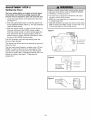
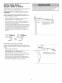
ADJUSTMENT
Program
the
STEP
Travel
1
Limits
Without a properly installed safety reversal system, persons
(particularly small children) could be SERIOUSLYINJURED
or KILLED by a closing garage door.
• Incorrect adjustment of garage door travel limits will
interfere with proper operation of safety reversal system.
• NEVERuse force adjustments to compensate for a binding
or sticking garage door.
• After ANY adjustments are made, the safety reversal system
MUST be tested. Door MUST reverse on contact with 1-1/2"
(3.8 cm) high object (or 2x4 laid flat) on floor.
Travel limits regulate the points at which the door
will stop when moving up or down. Follow the steps
below to set the limits.
- Indicator Light
-- Black Button
-- Purple Button
©
i/
ii /
To program
To prevent damageto vehicles, be sure fully open door
provides adequateclearance.
the travel limits:
Adjust the position of the door by using the black and
purple buttons. Black moves the door UP (open) and
purple moves the door DOWN (close).
Figure 2
1. Setting the UP position: Press and hold the black
button until the yellow indicator light starts flashing
slowly then release.
2. Push and hold the black button until the door reaches
the desired UP (open) position (Figure 2).
Indicator
Light
t
Push and hold
until the door
is at desired UP
position
NOTE: Check to be sure the door opens high enough for
your vehicle.
3. Push the remote control or door control (Figure 3).
This sets the UP (open) limit and begins closing the
door.
NOTE: Excessive movement of the motor unit will cause
premature wear. See Troubleshooting section.
Figure 3
4. Immediately when the door begins to move down,
press and release either the black or purple button.
This will stop the door.
or
5. Setting the DOWN position: Push and hold the
purple button until the door reaches the desired
DOWN (closed) position (Figure 4).
6. Once the door is closed, if there appears to have too
much pressure on the door, you may toggle the door
back and forth using the black and purple buttons to
reach the desired closed position.
Figure 4
Indicator Light
7. Push the remote control or the door control (Figure 3).
This sets the DOWN (close) limit and should bring the
door to the open position.
t
• If the opener is not stopping exactly where you
would like it, repeat steps 1 through 8 and program
the limits again.
Pusheither
button to stop
door at desired
DOWN
• When the unit stops in both the desired up (open)
and down (close) positions, proceed to
Adjustment Step 2, Setting the Force.
27
position
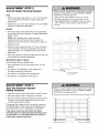
ADJUSTMENT
Setting
STEP
2
the Force
Without a properly installed safety reversal system, persons
(particularly small children) could be SERIOUSLYINJURED
or KILLED by a closing garage door.
• Too much force on garage door will interfere with proper
operation of safety reversal system.
• NEVERuse force adjustments to compensate for a binding
or sticking garage door.
• After ANY adjustments are made, the safety reversal system
MUST be tested. Door MUST reverse on contact with 1-1/2"
(3.8 cm) high object (or 2x4 laid flat) on floor.
The force setting button is located on the left panel
of the motor unit. The force setting measures the
amount of force required to open and close the door.
1. Locate the purple button on the left panel of the motor
unit (Figure 1).
2. Push the purple button twice to enter the opener into
Force Adjustment Mode (Figure 2). The LED (Indicator
Light) will flash quickly.
3. Push the remote control or control console (Figure 3).
The door will travel to the DOWN (close) position.
Push the remote control or control console again, the
door will travel to the UP (open) position. Push the
remote control or control console a third time to send
the door to the DOWN (close) position.
Figure 1
C;
C_
The LED (Indicator Light) will stop flashing when the
force has been learned.
ight
Button
Button
The opener has learned the forces required to open and
close your door.
The door must travel through a complete cycle, UP and
DOWN, in order for the force to be set properly. If the
opener cannot open and close your door fully, inspect
your door to insure that it is balanced properly and is not
sticking or binding. See page 3, "Preparing your
garage door."
Figure 2
ight
Push Purple button
twice to enter
unit into Force
Adjustment
Figure 3
28
Mode
Button
)le Button
ADJUSTMENT
Test
the
Safety
STEP
3
Reversal
System
Without a properly installed safety reversal system, persons
(particularly small children) could be SERIOUSLYINJURED
or KILLED by a closing garage door.
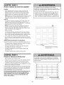
• Safety reversal system MUST be tested every month.
• After ANY adjustments are made, the safety reversal
system MUST be tested. Door MUST reverse on contact
with 1-1/2" high (3.8 cm) object (or 2x4 laid flat) on
the floor.
TEST
• With the door fully open, place a 1-1/2" (3.8 cm) board
(or a 2x4 laid flat) on the floor, centered under the
garage door.
• Operate the door in the down direction. The door must
reverse on striking the obstruction.
ADJUST
• If the door stops on the obstruction, it is not traveling
far enough in the down direction. Complete Adjustment
Steps 1 and 2.
NOTE: On a sectional door, make sure limit
adjustments do not force the door arm beyond a
straight up and down position. See Figure 3, page 25.
• Repeat the test.
• When the door reverses on the 1-1/2" (3.8 cm) board
(or 2x4 laid flat), remove the obstruction and run the
opener through 3 or 4 complete travel cycles to test
adjustment.
• If the unit continues to fail the Safety Reverse Test, call
for a trained door systems technician.
IMPORTANT SAFETY CHECK:
Test the Safety Reverse System after:
• Each adjustment of door arm length, limits, or force
controls.
• Any repair to or adjustment of the garage door
(including springs and hardware).
• Any repair to or buckling of the garage floor.
• Any repair to or adjustment of the opener.
ADJUSTMENT
Test The Protector
(Safety
Sensors)
STEP
4
System
®
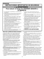
Without a properly installed safety reversing sensor, persons
(particularly small children) could be SERIOUSLYINJURED
or KILLED by a closing garage door.
• Press the remote control push button to open the door.
• Place the opener carton in the path of the door.
• Press the remote control push button to close the door.
The door will not move more than an inch (2.5 cm),
and the opener lights will flash.
The garage door opener will not close from a remote if
the indicator light in either sensor is off (alerting you to
the fact that the sensor is misaligned or obstructed).
If the opener closes the door when the safety
reversing sensor is obstructed (and the sensors are
no more than 6" (15 cm) above the floor), call for a
trained door systems technician.
r_
--
Safety Reversing Sensor
29
j
Safety Reversing Sensor
OPERATION
IMPORTANT SAFETY INSTRUCTIONS
To reduce the risk of SEVERE INJURY or DEATH:
1. READAND FOLLOWALL WARNINGSAND INSTRUCTIONS.
9. If one control (force or travel limits) is adjusted, the other
control may also need adjustment.
10. After ANY adjustments are made, the safety reversal
system MUST be tested.
11. Safety reversal system MUST be tested every month.
Garage door MUST reverse on contact with 1-1/2" high
(3.8 cm) high object (or a 2x4 laid flat) on the floor.
12. ALWAYSKEEPGARAGEDOORPROPERLYBALANCED
(see page 3). An improperly balanced door may not
reverse when required and could result in SEVEREINJURY
or DEATH.
2. ALWAYSkeep remote controls out of reach of children.
NEVERpermit children to operate or play with garage
control console push buttons or remote controls.
3. ONLYactivate garage door when it can be seen clearly, it is
properly adjusted, and there are no obstructions to door
travel.
4. ALWAYSkeep garage door in sight until completely closed.
NO ONESHOULDCROSSTHE PATHOFTHE MOVING
DOOR.
5. NO ONESHOULDGO UNDERA STOPPED,PARTIALLY
OPENDOOR.
13. ALL repairs to cables, spring assemblies and other
hardware, all of which are under EXTREMEtension, MUST
be made by a trained door systems technician.
14. To avoid SERIOUSPERSONALINJURYor DEATHfrom
electrocution, disconnect ALL electric and battery power
BEFOREperforming ANY service or maintenance.
6. If possible, use emergency releasehandle to disengage
trolley ONLYwhen garage door is CLOSED.Weak or broken
springs or unbalanced door could result in an open door
failing rapidly and/or unexpectedly.
7. NEVERuse emergency releasehandle unless garage
doorway is clear of persons and obstructions.
8. NEVERuse handle to pull garage door open or closed. If
rope knot becomes untied, you could fall.
Using
Your
Garage
Door
SAVETHESEINSTRUCTIONS.
6. If obstructed while opening, the door will stop.
Opener
7. If fully open, the door will not close when the beam is
broken. The sensor has no effect in the opening cycle.
Your Security+ ® opener and hand-held remote control
have been factory-set to a matching code which changes
with each use, randomly accessing over 100 billion new
codes. Your opener will operate with up to ten Security+ ®
remote controls, one Security+ ® Keyless Entry System,
and one accessory wall control. If you purchase a new
remote, or if you wish to deactivate any remote, follow
the instructions in the Programming section.
Activate
If the sensor is not installed, or is misaligned, the door
won't close from a hand-held remote. However, you can
close the door with the control console, the Outdoor Key
Switch, or Keyless Entry, if you activate them until down
travel is complete. If you release them too soon, the door
will reverse.
The opener lights will turn on under the following
conditions: when the opener is initially plugged in; when
power is restored after interruption; when the opener is
activated.
your opener with any of the following:
• The hand-held Remote Control: Hold the large push
button down until the door starts to move.
• The wall-mounted control console: Hold the push
button or bar down until the door starts to move.
They will turn off automatically after 4-1/2 minutes or
provide constant light when the Light feature on the
Control Console is activated. Bulb size is 100 watts
maximum.
• The Keyless Entry (see Accessories): If provided with
your garage door opener, it must be programmed
before use. See Programming.
Security,I _ light feature: Lights will also turn on when
someone walks through the open garage door. With a
Motion Detecting Control Console, this feature may be
turned off as follows: With the opener lights off, press
and hold the light button for 10 seconds, until the light
goes on, then off again. To restore this feature, start with
the opener lights on, then press and hold the light button
for 10 seconds until the light goes off, then on again.
When the opener is activated (with the safety
reversing sensor correctly installed and aligned)
1. If open, the door will close. If closed, it will open.
2. If closing, the door will reverse.
3. If opening, the door will stop.
4. If the door has been stopped in a partially open
position, it will close.
5. If obstructed while closing, the door will reverse. If the
obstruction interrupts the sensor beam, the opener
lights will blink for five seconds.
30
Using the Wall.Mounted
Control
Console
Bar
Motion Detecting
Light On/Off
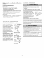
THE MOTION DETECTING CONTROL CONSOLE
Press the push button to open or close the door. Press
again to reverse the door during the closing cycle or to
stop the door while it's opening.
This control console contains a motion detector that will
automatically turn on the light when it detects a person
entering the garage. This feature can be easily turned off
for extended work light use.
Learn
Hour
Minute
Language
Degrees (F/C)
ight Button
Lock Button
Light Feature
Learn Feature
Press the Light button to turn the opener light on or off. It
will not control the opener lights when the door is in
motion. If you turn it on and then activate the opener, the
light will remain on for 4-1/2 minutes. Press again to turn
it off sooner. The 4-1/2 minute interval can be changed to
1-1/2, 2-1/2, or 3-1/2 minutes as follows: Press and hold
the Lock button until the light blinks (about 10 seconds).
A single blink indicates that the timer is reset to 1-1/2
minutes. Repeat the procedure and the light will blink
twice, resetting the timer to 2-1/2 minutes. Repeat again
for a 3-1/2 minute interval, etc., up to a maximum of four
blinks and 4-1/2 minutes.
The control console is equipped with a LEARN button to
assist in learning remote controls to the unit. Press the
LEARN button once to initiate LEARN mode and the
display will show 'Learn Remote Control - Press Learn
Button Again to Confirm.' Press the LEARN button a
second time and the display will show 'Learn Mode Press Remote Control Button to Learn Remote.' Press
the button of the remote control to be learned and the
worklight will blink to confirm the remote control has
been learned.
Hour and Minute Feature
Press or hold either of these side buttons to increment
the hour or minute displayed on the LCD display.
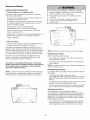
When using the opener lights as working lights, we
recommend that you first disable the motion sensor.
Motion Detecting Light Feature: The opener light will
turn on automatically when a person walks in front of the
wall-mounted control console. This feature works by
detecting motion and body heat and may not work in
temperatures around IO0°F, 37.7C. The opener light will
come on for 5 minutes, then shut off automatically if no
additional motion or heat differential is calculated.
Language
Feature
To disable this feature, press the Automatic Light On/Off
button on the left side of the control console.
Additional
hand-held
We recommend that you disable the motion sensor when
using the opener lights as working lights. Otherwise, they
will turn off automatically if you are working beyond the
sensor's range.
To control the opener lights:
Press this side button to toggle between the three
languages - English, Spanish, and French.
Degrees F/C Feature
Press this side button to toggle the temperature units
between Fahrenheit and Celsius.
feature when used with the 3-Function
remote
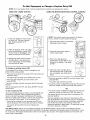
1. With the door closed, press and
hold a small remote button that you
want to control the light.
Lock Feature
2. Press and hold the Light button on
the control console.
Designed to prevent operation of the door from hand-held
remote controls. However, the door will open and close
from the control console, the Outside Keylock and the
Keyless Entry Accessories.
3. While holding the Light button, press and hold the Lock
button on the control console.
4. After the opener lights flash, release all buttons.
To activate, press and hold the Lock button for 2
seconds. The push bar light will flash as long as the Lock
feature is on.
To turn off, press and hold the Lock button again for
2 seconds.The push bar light will stop flashing. The Lock
feature will also turn off whenever the "learn" button
is activated.
31
Care
of Your
MAINTENANCE
Opener
THE REMOTE CONTROL BATTERY
SCHEDULE
Once a Month
To prevent possible SERIOUSINJURY or DEATH:
• NEVERallow small children near batteries
• Manually operate door. If it is unbalanced or binding,
call a trained door systems technician.
• If battery is swallowed, immediately notify doctor
• Check to be sure door opens and closes fully. Adjust
limits and/or force if necessary (see pages 27 and 28).
The lithium battery should
produce power for up to
5 years. To replace battery,
use the visor clip or
screwdriver blade to pry open
the case as shown. Insert
battery positive side up (+).
• Repeat the safety reverse test. Make any necessary
adjustments (See Adjustment Step 3).
Once a Year
• Oil door rollers, bearings and hinges. The opener does
not require additional lubrication. Do not grease the
door tracks.
Open this end
first to avoidJ
L..._
crack:ing _
d_._--_..._/--_J
hous_
Dispose of old battery properly.
NOTICE:To comply with FCCand or Industry Canadarules (IC), adjustment or modifications of
this receiver and/or transmitter are prohibited, exceptfor changing the code setting or replacing
the battery. THEREARE NOOTHERUSERSERVICEABLEPARTS.
Tested to Comply with FCC Standards FORHOME OR OFFICEUSE.Operation is subject to the
following two conditions: (1) this device may not causeharmful interference, and (2) this device
must acceptany interferencereceived,including interferencethat may cause undesired operation.
To Open
the
DlSCONNECTTHE
Door
Manually
TROLLEY:
The door should be fully closed if
possible. Pull down on the
emergency release handle (so
that the trolley release arm snaps
into a vertical position) and lift the
door manually. The lockout
feature prevents the trolley from
reconnecting automatically, and
the door can be raised and
lowered manually as often as
necessary.
TO RE-CONNECTTHE
TROLLEY:
Pull the emergency release
handle toward the opener at an
angle so that the trolley release
arm is horizontal. The trolley will
reconnect on the next UP or
DOWN operation, either
manually or by using the control
console or remote.
To prevent possible SERIOUSINJURYor DEATHfrom a
falling garage door:
• If possible, useemergency releasehandle to disengage
trolley ONLYwhen garage door is CLOSED.Weak or
broken springs or unbalanced door could result in an open
door falling rapidly and/or unexpectedly.
• NEVERuse emergency release handle unless garage
doorway is clear of persons and obstructions.
• NEVERuse handle to pull door open or closed. If rope knot
becomes untied, you could fall.
Trolley
Trolley -Release Arm
(In Manual
Disconnect
Position)
.°_
b
Lockout
(Manual
position
disconnect)
Trolley
e
Emergency
"" "__
Release Handle _ '_
._
(Down and Back) _"_._'
%
To reconnect
32
Battery
Backup
OPERATING INSTRUCTIONS
1. Test the installed
To reduce the risk of FIREor INJURYto persons:
• Disconnect ALL electric and battery power BEFORE
performing ANYservice or maintenance.
• Use only Craftsman part #41A822 for replacement battery.
• Do NOT dispose of battery in fire. Battery may explode.
Checkwith local codes for disposal instructions.
battery with the motor unit.
To test the battery, disconnect the motor unit power cord
from the electrical outlet.
• A solid orange LED indicates the battery is operating
on battery power,
• A flashing orange LED with beep indicates the unit is
operating on battery power and that the battery charge
is low,
• To test the battery is functioning properly, open and
close the garage door,
• Re-connect the motor unit power cord back into the
electrical outlet.
• Verify that the green LED is flashing on the BBU
(indicates that the battery is now charging).
Battery
Status LED
• Test completed,
2. Charge the battery.
• Battery will take 24 to 48 hours to fully charge.
A fully charged battery supplies 12V DC to the motor unit
for one to two days of normal operation during an
electrical power outage. If the battery voltage drops too
low, the batteries will disconnect and the motor unit will
no longer operate under battery power.
NOTE: LED is most visible with worklight off.
GREEN LED:
After the electrical power has been restored, the battery
will recharge within 48 hours. Under normal usage
batteries will last 3 to 5 years.
• A flashing LED indicates the battery is being charged.
All systems are normal
• A solid LED light indicates the battery is fully charged.
NOTE: Battery does not have to be fully charged to
operate the motor unit.
To obtain maximum battery life and prevent damage,
disconnect the battery when the motor unit is
unplugged for an extended period of time.
ORANGE LED:
The motor unit has lost power and is operating off of the
battery.
NOTE: Door operation may be limited until battery is fully
charged. The motor unit's lights will not turn on during
battery mode.
• A solid LED with beep, sounding approximately every
2 seconds, indicates the motor unit is activating the
door and is operating off of the battery.
• A flashing LED with beep, sounding every 30 seconds,
indicates battery is low.
• Once the power is restored the battery will recharge.
This is indicated by a flashing green LED.
RED LED:
• If a red LED remains on when the power is restored,
and is accompanied by a beep sounding every 30
seconds, please call for service.
• To obtain maximum battery life and prevent damage,
also disconnect the battery if you unplug the motor unit
while on vacation or any other extended period of
time.
33
Having
a Problem
(Troubleshooting)
Bell Wire
NOTE: Always unplug battery prior to troubleshooting.
1. My door will not close and the light bulbs blink on
my motor unit: The safety reversing sensor must be
connected and aligned correctly before the garage
door opener will move in the down direction.
• Verify the safety reversing sensors are properly
installed, aligned and free of any obstructions. Refer
to Installation Step 11: Install The Protector Syster_.
....... ii
• Check diagnostic LED for flashes on the motor unit
then refer to the Diagnostic Chart on the
following page.
f
Safety Reversing Sensor
2. My remotes will not activate the door:
• Verify your Motion Detecting Control Console does
not display "Lock Mode." If it does, deactivate the
Lock Mode following the instructions for Using the
Motion Detecting Control Console.
Sending Eye Safety
Reversing Sensor
(Amber Indicator Light)
Receiving Eye
Safety
Reversing
Sensor
(Green Indicator Light)
• Reprogram remotes following the programming
instructions. Refer to Programming.
• If remote will still not activate your door, check
diagnostic LED for flashes on motor unit then refer to
Diagnostic Chart on the following page.
3. My door reverses for no apparent reason: Repeat
safety reverse test after adjustments to force or travel
limits. The need for occasional adjustment for the force
and limit settings is normal. Weather conditions in
particular can affect door travel.
6. My motor unit hums briefly:
• First verify that the trolley is against the stop bolt.
• Release the door from the opener by pulling the
Emergency Release Rope.
• Manually bring the door to a closed position.
• Manually check door for balance or any binding
problems.
• Loosen the belt by adjusting the outer nut4 to 5
turns. This relieves the tension.
• Refer to Adjustment Step 2, Setting the Force.
• Run the motor unit from the remote control or control
console. The trolley should travel towards the door
and stop. If the trolley re-engages with the door, pull
the Emergency Release Rope to disengage.
• Decrease the UP travel.
4. My door reverses for no apparent reason after fully
closing and touching the floor: Repeat safety
reverse test after adjustments to force or travel limits.
The need for occasional adjustment for the force and
limit settings is normal. Weather conditions in particular
can affect door travel.
• Refer to Adjustment Step 1, Program the
Travel Limits.
5. My lights will not turn off when door is open:
• The garage door opener is equipped with a security
light feature. This feature activates the light on when
the safety reversing sensor beam has been
obstructed. Refer to Operation section; Using the
Wall Mounted control console, Light Feature.
_1_
1-1/4"
(3.18 cm)
• Re-Tighten the outer nut until the trolley spring is
approximately 1-1/4" (3.18 cm) in length.
• If the trolley does not move away from the bolt,
repeat the steps above.
7. Battery status LED is not lit properly:
• Check battery connections.
34
Bell Wire
Safety Reversing
Your garage door opener is programmed with
self-diagnostic capabilities. The "Learn" button/diagnostic
LED will flash a number of times then pause signifying it
has found a potential issue. Consult Diagnostic Chart below.
Sensor
Diagnostic
Chart
Symptom: One or both of the Indicator lights on the safety reversing sensors
do not glow steady.
Safety reversing sensors
wire open (broken
or disconnected).
OR
• Inspect sensor wires for a short (staple in wire), correct wiring polarity
(black/white wires reversed), broken or disconnected wires, replace/attach
as needed.
• Disconnect all wires from back of motor unit.
• Remove sensors from brackets and shorten sensor wires to 1-2 ft (30-60 cm) from
back each of sensor.
Safety reversing sensors
wire shorted or
black/white wire
reversed.
Control console or
wire shorted.
• Reattach sending eye to motor unit using shortened wires. If sending eye indicator
light glows steadily, attach the receiving eye.
• Align sensors, if the indicator lights glow replace the wires for the sensors. If the
sensor indicator lights do not light, replace the safety reversing sensors.
...• Symptom: LED is not fit on control console.
• Inspect control console/wires for a short (staple in wire), replace as needed.
• Disconnect wires at control console, touch wires together. If motor unit activates,
replace control console.
• If motor unit does not activate, disconnect control console wires from motor unit.
Momentarily short across red and white terminals with jumper wire. If motor unit
activates, replace control console wires.
•..0 Symptom: Sending indicator
dim or flashing.
Safety reversing sensors
slightly misaligned
(dim or flashing LED).
light is
• Realign receiving eye sensor, clean lens and secure brackets.
• Verify door track is firmly secured to wall and does not move.
•..0 Symptom:
Possible RPM sensor
failure. Unplug to reset.
light glows steadily, receiving indicator
RPM Sensor = Short travel 6-8" (15-20 cm).
• Unplug unit to reset. Try to operate motor unit, check diagnostic code.
• If it is still flashing 5 times and motor unit moves 6-8" (15-20 cm), replace RPM
sensor.
• If motor unit doesn't operate, motor unit is overheated. Wait 30 minutes and retry. If
motor unit still will not operate replace logic board.
35
LCD Motion
Detecting
Console
Messages
Control
The following messages are contained within the LCD
Motion Detecting Control Console and may appear
during the operations of the unit:
""O
Meaning: This message will appear if the Safety Reversing Sensors are out of
alignment, if they are blocked or if the wiring is disconnected. To clear message from
Control Console do the following:
• Check to see that area is clear between the Safety Reversing Sensors.
• Check to see that the Safety Reversing Sensors are not misaligned.
• Realign receiving eye sensor, clean lens and secure brackets.
• Verify door track is firmly secured to wall and does not move.
• Check to see that the Safety Reversing Sensors' wires are connected to the motor unit.
• If message has not cleared after the above checks, refer to message #2.
""0
Meaning: This message will appear if the Safety Reversing Sensors are miswired.
To clear the message, do the following:
• Inspect the safety reversing sensor wires for a short (staple in wire), correct wiring
polarity (black/white wires reversed), replace/attach as needed.
• Disconnect all wires from back of motor unit.
• Remove safety reversing sensors from brackets and shorten sensor wires to 1-2 ft.
(30-60 cm) from back of each sensor.
• Reattach sending eye to motor unit using shortened wires. If sending eye indicator light
glows steadily, attach the receiving eye.
• Align sensors, if the indicator lights glow replace the wires for the sensors. If the sensor
indicator lights do not light, replace the safety reversing sensors.
""0
Meaning: This message will appear when the 'LEARN'button has been pressed on
the Control Console. Pressing the 'LEARN'button again will allow the user to
program an additional remote control to the opener.
"'0
Meaning: This message will appear when the 'LEARN" button has been pressed a
second time on the Control Console or anytime on the opener. The opener
is ready to program another remote control by simply pressing the remote control
button. Once the opener has 'LEARNED" the remote control, the worklight will blink
one time.
"e
Meaning: This message will appear when the 'LOCK'button
has been pressed and
held for more than one second. This feature will disable the opener from receiving
remote control signals. To exit 'LOCK" mode, press and hold the button
for more than one second.
SAFETY SENSORS
CHECK ALIGNMEN_
BLOCKAGE OR
MlSWlRING SEE
OWNER'S MANUAL
SAFETY SENSORS
MALFUNCTION
CHECK MISWlRING
SEE OWNER'S
MANUAL
LEARN REMOTE
CONTROL PRESS
LEARN BUTTON
TO CONFIRM
LEARN MODE PRESS
REMOTE CONTROL
BUTTON TO
PROGRAM REMOTE
LOCK MODE REMOTE
CONTROL LOCKED
OUT PRESS LOCK
BUTTON TO ENABLE
REMOTE
•..Q Meaning: This message will appear when the 'LANGUAGE" button has been pressed.
Pressing the button will toggle to the next language.
ENGLISH, FRAN(_AIS
AND ESPANOL
....•
MOTION SENSING ON
MOTION SENSING
OFF
Meaning: This message will appear when the Motion Sensing button is pressed.
motion detector will toggle on or off with each press of the button.
36
The
PROGRAMMING
NOTICE: If this Security.l._ garage door opener is operated with a non-rolling code transmitter, the technical measure in
the receiver of the garage door opener, which provides security against code-theft devices, will be circumvented. The
owner of the copyright in the garage door opener does not authorize the purchaser or supplier of the non-rolling code
transmitter to circumvent that technical measure,
Your garage door opener has already been programmed at the factory to operate with your hand-held remote control,
The door will open and close when you press the large push button,
Below are instructions for programming your opener to operate with additional Security÷ ® remote controls,
To Add
USING THE "LEARN"
or
Reprogram
a Hand-held
BUTTON
Remote
Control
USING THE MOTION DETECTING CONTROL CONSOLE
/
1, Press and release the "learn" button
on the motor unit. The learn indicator
light will glow steadily for 30
seconds.
_!z_£1!s_sL i
1::i_
o
1. Press the Learn button on the Motion
Detecting Control Console,
\ ][[
2, Press the Learn button again to confirm
Learn Mode,
2, Within 30 seconds, press and hold
the button on the hand-held remote*
that you wish to operate your garage
door.
3. Press the button on the hand-held
remote* that you wish to operate your
garage door.
3, Release the button when the motor
unit lights blink. It has learned the
code, If light bulbs are not installed,
two clicks will be heard,
To Erase
All Codes From
Unit Memory
/
4. When the motor unit lights blink, it has
learned the code. If light bulbs are not
installed, two clicks will be heard.
Motor
To deactivate any unwanted remote, first
erase all codes:
/
I;
\ _ii
Press and hold the purple "learn" button on
motor unit until the learn indicator light goes
out (approximately 6 seconds). All previous
codes are now erased, Reprogram each
remote or keyless entry you wish to use,
*3.Function
If provided with your garage door opener, the large button
is factory programmed to operate it, Additional buttons on
any Security÷ ®3-Function
remote or compact remote
._d_A
_ _
can be programmed to
operate other Security÷ _
\
garage door openers.
IJ I
i ui
[i_[I
\l,
Remotes
,V
37
To Add,
NOTE:
Your new Keyless
USING THE "LEARN"
Entry
Reprogram
or Change
must be programmed
to operate
BUTTON
I--]i(
Detecting
1. Press the four buttons for the present
hold the # button.
CONSOLE
Control
Console.
3. Enter a four digit personal
identification number (PIN) of your
choice on the keypad. Then press
ENTER.
/
4. When the motor unit lights blink, it
has learned the code. If light bulbs
are not installed, two clicks will be
heard.
by one
PIN, then press and
light will blink twice. Release the # button.
2. Press the temporary 4-digit PIN you have chosen, then
press ENTER.
PIN you have chosen, then
The opener light will blink four times.
3. To set the number of hours this temporary PIN will work,
press the number of hours (up to 255), then press _.
The motor unit lights will blink once when the PIN has been
learned.
Test by pressing the new PIN, then press ENTER. The door
should move.
To set a temporary
CONTROL
PIN
If the existing PIN is known, it may be changed
person without using a ladder.
The opener
DETECTING
2. Press the Learn button again to
confirm Learn Mode.
...I
unit lights blink. It has learned the
code. If light bulbs are not installed,
two clicks will be heard.
2. Press the new 4-digit
press ENTER.
door opener.
1. Press the Learn button on the Motion
3. Release the button when the motor
known
PIN
NOTE: This method requires two people if the Keyless
Entry is already mounted outside the garage.
2. Within 30 seconds, enter a four digit
personal identification number (PIN)
of your choice on the keypad. Then
press and hold the ENTER button.
an existing,
your garage
Entry
USING THE MOTION
1. Press and release the "learn" button
on motor unit. The learn indicator
light will glow steadily for 30
seconds.
To change
a Keyless
OR
3. To set the number of times this temporary PIN will work,
press the number of times (up to 255), then press #.
PIN
You may authorize access by visitors or service people with
a temporary 4-digit PIN. After a programmed number of
hours or number of accesses, this temporary PIN expires
and will no longer open the door. It can be used to close the
door even after it has expired. To set a temporary PIN:
1. Press the four buttons for your personal entry PIN (not
the last temporary PIN), then press and hold the ¢ button.
The opener light will blink three times. Release the
button.
The opener light will blink once when the temporary
has been learned.
PIN
Test by pressing the four buttons for the temporary PIN,
then press ENTER. The door should move. If the temporary
PIN was set to a certain number of openings, remember
that the test has used up one opening. To clear the
temporary password, repeat steps 1-3, setting the number
of hours or times to 0 in step 3.
One Button Close: Opener can be closed by pressing only the ENTER button if the one button close feature has been
activated. This feature has been activated at the factory. To activate or deactivate this feature press and hold buttons 1 and 9
for 10 seconds. The keypad will blink twice when the one button close is active. The keypad will blink four times when one
button close is deactivated.
38
REPAIR
Rail
PARTS
Assembly
Parts
6
Installation
KEY
NO.
PART
NO.
1
2
3
4
5
6
7
4A1008
Master link kit
41C5141-1
41A5665-2
41 B4103
144C54
41A5250
12D598-1
Complete trolley assembly
Complete rail
Spring trolley nut
Idler pulley
Full belt assembly
"U" bracket
NOT SHOWN
183A 163
Wear pads
DESCRIPTION
Parts
KEY
NO.
1
3
PART
NO.
1
41A6317
2
41A6140-1
Motion detecting control console (LCD)
3-Function remote control case
(no circuit board)
3
10A20
3V 2032 Lithium battery
4
29B137
Visor clip
5
41 D543-1
Keyless entry keypad cover
6
41 D541
Keyless entry battery cover
7
41A2828
8
41 B4494-1
Emergency release rope and handle
assembly
2-Conductor bell wire: white and
white/red
9
41A5047-3
Header bracket with clevis pin and
fastener
10
41A5047-1
Door bracket with clevis pin and
fastener
11
178B35
Curved door arm section
12
178B34
Straight door arm section
13
12B776
Hanging bracket
14
41A5034
Safety reversing sensor kit (receiving
and sending eyes) with 3' (.9 m)
2-conductor bell wire attached
15
41A5266-1
Safety reversing sensor bracket
16
41A822
Battery
NOT SHOWN
41A5257-5
Installation hardware bag
(includes hardware listed on page 7)
Owner's manual
4
11
13
DESCRIPTION
14
15
114A3280
39
Motor
Unit Assembly
Parts
.2
KEY
NO.
PART
NO.
1
2
3
4
41C76
KEY
NO.
DESCRIPTION
PART
NO.
DESCRIPTION
Belt cap and sprocket
Line cord
7
41A6268
41 B4245
End panel with battery door
and screw
41 B4375-3
Terminal block with screws
8
41C190
Transformer
41A6281
Wire harness kit Complete
9
41D503-2
Cover
41A6282
Battery wires and plug
10
108D77
Light lens
41 A6327
Light socket wires and plug
11
175B88
Light socket
41 A6328
41 D794
RPM/passpoint
5
6
41 DB102-2
Receiver logic assembly
with:
and harness
wires with plug
NOT SHOWN
Motor with positioning sensor
41A822
40
Battery kit
CONTENIDO
Introducci6n
2- 7
Revision de los simbolos y terminos de seguridad
..........
Preparaci6n de la puerta de su cochera ..................
Herramientas necesarias ..............................
Planificaci6n
......................................
Inventario de la caja de carton
.........................
Montaje
2
3
3
Ajuste la fuerza
Fije el riel a la unidad del motor
........................
Instale la polea Ioca ..................................
..........................
27
....................................
28
Pruebe el sistema de retroceso de seguridad .............
Pruebe La Sistema de Proteccion _ .....................
6
Operaci6n
7
Instrucciones
30.36
importantes de seguridad
.................
8
C6mo usar la consola de control de pared ...............
31
9
Mantenimiento
9
C6mo abrir la puerta manualmente .....................
Reserva de bateria .................................
de su abridor de puerta de cochera
10
Si tiene algt3n problema (Diagnostico de fallas)
Fije la tensi6n de la banda ............................
11
Tabla de diagn6stico
Instrucci6nes
Determine
11.26
importantes
para la instalaci6n
d6nde va a instalar
Instale la mensula
del cabezal
Coloque
el riel en la mensula
Coloque
el abridor
en posici6n
...........
la mensula del cabezal
......................
del cabezal
.............
......................
30
30
Instale la banda y sujete el reten de la cubierta
de la banda .......................................
Instalaci6n
29
29
C6mo usar su abridor de puerta de cochera ..............
8-11
Monte el riel y instale el trole ...........................
27.29
Ajuste el limite del recorrido
4-5
Inventario de piezas ..................................
Ajustes
........
32
32
33
...........
34
................................
35
Mensajes de la consola de control
de deteccion de movimiento de la LCD ..................
36
11
...12
13
14
15
C6mo
Programar
el Abridor
37.38
C6mo agregar o reprogramar un
control remoto manual ...............................
37
Para borrar todos los codigos de la memoria
de la unidad la motor ................................
37
Controles remotos de 3 funciones ......................
37
Cuelgue el abridor
...............................
Instale la consola de control ..........................
16
17
Instale la bateria
18
C6mo agregar, reprogramar o cambiar un
c6digo de entrada sin Ilave ...........................
18
Accesorios
39
Garantia
39
...................................
Instale las luces ....................................
Instale la manija y la cuerda de emergencia
..............
18
Requisitos para la instalacion electrica ..................
Instale La Sistema de Protecci6n ® ...................
19
20-22
Fije la mensula de la puerta ........................
23-24
Conecte el brazo de la puerta a! trole
25-26
................
38
Nbmeros
de Servicio
Contratapa
INTRODUCClON
Revisi6n
de
de Seguridad
los
Simbolos
y T_rminos
Este abridor de puerta de cochera ha sido disefiado y probado para un funcionamiento seguro, siempre y cuando se instale, se
pruebe, se opere y se le de mantenimiento como se indica en este manual, cumpliendo a! pie de la letra con todas las advertencias
instrucciones generales aqui contenidas.
Mecanica
Electrica
e
Estas advertencias y/o simbolos de seguridad que aparecen en
este manual le alertaran de que existe el riesgo de una lesion
seria o de muerte si no se siguen las instrucciones
correspondientes. El peligro puede ser electrico (electrocucion)
o mecanico. Lea las instrucciones con mucho cuidado.
Cuando vea esta palabra y/o simbolo de seguridad en este
manual, le alertara de que existe el riesgo de daflar la puerta
de la cochera y/o el abridor si no se siguen las instrucciones
correspondientes. Lea las instrucciones con mucho cuidado.
Preparaci6n
de la puerta
de su cochera
Antes de comenzar:
Para evitar una LESIONGRAVEo INCLUSOLA MUERTE:
• Quite los seguros.
• Retire cualquier cuerda o cable que este conectado
a la puerta.
• Haga la siguiente prueba con su puerta para verificar que
este balanceada y que no se atore ni se pandee:
1. Levante la puerta hasta la mitad de su recorrido como se
muestra. Suelte la puerta. Siesta. balanceada, debera
mantenerse en esa posicion con solo el soporte de los
resortes.
2. Suba y baje la puerta; observe si se atora con algo o si
se pandea.
• SIEMPREflame a un t_cnico profesional para que le d_ servicio a
su puerta de cochera si _sta se atora, se pandea o est,.
desbalanceada.Una puerta de cochera que no est_ bien
balanceadapuede que no retroceda como se requiere.
• NUNCAintente aflojar, mover ni ajustar la puerta de su cochera,
los resortes de la puerta, los cables, las poleas, las m_nsulas ni la
tornilleria, pues todos estos elementos est_n bajo tensi6n
EXTREMA.
• Quite TODOSlos seguros y retire TODASlas cuerdas conectadas
a la puerta de cochera ANTESde instalar y operar el abridor de la
puerta de cochera para evitar que se enreden.
Si su puerta se atora o se pandea, o no esta balanceada
Ilame a un tecnico especializado en sistemas de puertas.
Para evitar que se da_en el puerta y el abridor:
• SIEMPREquite los seguros ANTESde instalar y/o de operar el
abridor.
• SOLAMENTEopere el abridor de puerta de cochera con corriente
de 120V, 60Hz con objeto de evitar su mal funcionamiento y que
el abridor se da_e.
Puerta seccional
Puerta de una sola pieza
Herramientas
necesarias
Durante el montaje, instalaci6n y ajuste del abridor, las
instrucciones le indicara.n como usar las herramientas que
aparecen en la siguiente ilustracion.
L_piz
Sierra de mano
Cinta de medir
Cortadorade alambre
Taladro
Martillo
Brocas de 3/16, 5/16
Destor nillador
y 5/32de pulgada
Escalera
0
0 0 7/t o o j er :s12
Llave inglesa
Planificaci6n
Identifique la altura y el tipo de su puerta de cochera. Revise el
area de su cochera y observe si alguna de las siguientes
instalaciones corresponden a la suya. A veces se requieren
materiales adicionales, asi que tal vez sea conveniente tener
esta hoja y las ilustraciones correspondientes a mano cuando
inicie la instalacion de su abridor.
Dependiendo de sus necesidades individuales, es posible que
en algunos casos vaya a necesitar materiales o herramientas
que no se incluyen con este producto.
• Instalaci6n Paso 1 - Observe la pared o el cielo raso justo
por encima de la puerta de la cochera. La mensula del
cabezal debe estar firmemente sujeta a los soportes de la
estructura.
• Observe el punto donde la puerta hace contacto con el piso.
El espacio entre la base de la puerta y el piso no debe
exceder 6 mm (1/4 de pulgada). Si no es asi, se corre el
riesgo de que el sistema de retroceso de emergencia no
funcione correctamente. Vea Ajustes, Paso 3. Sera necesario
reparar ya sea e! piso o la puerta.
INSTALACION
CON UNA PUERTA SECCIONAL
• Si tiene una puerta de acero, aluminio, fibra de vidrio o con
paneles de vidrio, necesitara refuerzos verticales y
horizontales en la puerta. (Instalaci6n, Paso 12.)
• El abridor se debe instalar por encima del centro de la
puerta, pero si existe algOn resorte de tension o placa de
apoyo en el paso de la mensula del cabezal, se puede
instalar hasta a 1.22 m (4 pies) a la derecha o a la izquierda
del centro de la puerta. Vea Instalaci6n, Pasos del 1 a112.
• Instalaci6n Paso 5 - Si el plaf6n o cielo raso de su cochera
tiene acabado, es posible que necesite una mensula de
soporte y/o mas pernos y tornilleria para la instalaci6n.
• Si su puerta es de mas de 2.t3 m (7 pies) de altura, vea
Extensiones de riel en la secci6n de Accesorios.
• Instalaci6n Paso 11 - Dependiendo del tipo de construccion
de su cochera, es posible que necesite mensulas de
extensi6n o bloques de madera para instalar los sensores.
• Instalacion Paso 11 - El montaje en el piso del sensor que
activa el sistema de retroceso de seguridad podria requerir
piezas que no se incluyen.
• ),Hay otra puerta que de acceso a la cochera? Si no es asi,
sera necesario contar con el sistema de Ilave de emergencia
Modelo 139.53702. Vea la p_tgina de Accesorios.
INSTALACION
CON UNA PUERTA SECCIONAL
CIELO RASO CON ACABADO
Se requiere mensulade
soporte y tornillos e
sujetadores.Yea la pagina 16.
Losrefuerzosverticales y horizontalesson
necesados para las puertasde cochera de
matedalesm_s Dianos (fibrade vidrie, acero,
aluminio o puertas con panelesde vidrio).
Vea la pagina 23, donde encontrar_m_s detalles.
: \\
Pared delantera
Resortede extensi6n
0
Resortede torsi6n
Unidad de
control de
la puerta,
instalada
Unidaddel motor
Puertade
acceso
en la paled
M_nsula
deI cabezaI Perno de
ENPOSICIONCERRADA
Trole
O
Banda
Sensordel sistema
de retrocesode seguridad
El espacioentre la base de
la puerta y el piso nodebe
exceder 6 mm (1/4 de pulg.).
Cuerday manija
del sistema de
[iberaci6n
de emergencia
Sensordel sistema
de retrocesode seguridad
Braze
curvede
la puerta
ired
lantera
Jerta --tla
chera
de [a
puerta
Planificaci6n
INSTALACION
(continba)
CON PUERTAS DE UNA SOLA PIEZA
Sin un sistemaderetrocesode seguridadquefuncione
debidamente, al cerrar la puerta de la cochera se corre el riesgo de
• Generalmente una puerta de una sola pieza no requiere
refuerzos adicionales. Si usted tiene una puerta de material
liviano y quiere reforzarla, consulte la informaci6n respecto a
puertas seccionales, contenida en tnstalaci6n, Paso 12.
quelas personas(y en particularlos nifios pequefios)sufran
LESIONES
GRAVES
o INCLUSOLA MUERTE.
• El espacio entre la basede la puerta de la cochera y el piso [t0
DEBEexceder6 mm (1/4de pulgada).Deno ser asi, el sistema
• Dependiendo del diseflo de su puerta, tal vez necesite
piezas de montaje adicionales para la mensula de la puerta
(Paso 12).
PUERTA DE UNA SOLA PIEZA
SIN CARRIL
de retroceso de seguridad no va a funcionar debidamente.
• El piso o la puerta de la cochera SE DEBEreparar para eliminar
este espacio.
CIELO RASOCON ACABADO
/
/'
Se requiere m6nsulade soporte '
y torniflos o sujetadores,
Vea [a p_gina 16,
Riel
Paredde[antera
Unidaddel motor
Unldad de controlde la puerta,
instalada en la pared
J
Puertade
acceso
Sensordel sistema de
retrocesode segurldad
El espac[oentre [a base
la puerta y el piso nodebe de
exceder 6 mm (1/4 de pulg.).
Sensor del sistemade
retrocesode seguddad
Fared
c ._lantera
PUERTA DE UNA PIEZA CON CARRIL
EN POSICIONCERRADA
Pemode paro
de[ trole I
Banda
Trole
I
[
Puert_
Pared
6nsula
Brazo de la
delcabeza[
delanter_
puertacurvo___/
oc ()(
_/'J
_/_
_/_
/"_
Sensor del sistemade
retroceso deseguddad
El espacioentre la base de
la puerta y el plso no debe de
exceder 6 mm (1/4 de pulg.).
S_nsor del
sistemade
retrocesode seguddad
la puerta
Puertade
lacochera
( o(Jooo
'-_
R,e,
)',
razo reclo
de la puerta
_
[
[
del sistema de
I[beraci6n
de emergencla
Inventario
de la Caja
de Cart6n
Su abridor viene empacado en una caja de carton que contiene
el motor y las piezas que se muestran en la siguiente
ilustracion. Tome nota de que los accesorios dependeran del
modelo que haya comprado. Si falta alguna pieza, revise con
cuidado el material de empaque ya que en ocasiones las
piezas se atoran en e! mismo. Toda la tornilleria y las piezas
necesarias para el montaje e instalaci6n de su puerta se
ilustran en la siguiente pagina. Conserve la caja y los
materiales de empaque hasta que la instalaci6n y el ajuste se
hayan terminado.
I
r
[
SECURITY.lt,e
Controlesremoto de 3 funciones (2)
Bateria
Consola de control de
detecci6nde movimiento(LCD)
Trole
Cubiertade la banda
SECURITY,_÷
Entrada sin Ilave
Secdonescentral
y posterior del riel
Unidaddel motor con dos lente
M_nsula en 'U'
PoleaLoca
Mensulas para colgar
Banda
Secci6n delantera
j
Secci6n curva del
brazo de la puerta
Mensuladel cabeza[
M_nsulade la puerta
Cablede campanade 2 conductores
Blanco y blanco/rojo
M_nsulas paralos sensores del
sistema de retrocesode seguridad (2)
The ProtectorSysteme
Sensores del sistemade
retrocesode seguridad (un ojo emisor
y un ojo receptor)conectadosa un cable
de campanade dos conductores.
Blanco y blancdnegro (2)
Etiquetasde
seguridad y
literatura
Secci6n recta
del brazo de
la puerta
Inventario
de Piezas
Antes de la instalaci6n, organice todas las piezas en grupos como se muestra en la siguiente ilustraci6n.
TORNILLER|A
Y PIEZAS PARA EL MONTAJE
©
Tuercade
1/4-20 de pulg. (2)
Resorte/tuerca del trole (1)
Arandelade
3/8 de pulg. (1)
Tuercade
3/8 de pulg. (1)
i
Pemo de
1/4-20xl-3/4 de pulg. (2)
Enlace maestro(2)
PernoIoco (1)
Flecha roscada del trole (1)
TORNILLERJA
Y PIEZAS PARA LA INSTALACION
O
Pemo de coche
de 1/4-20xl/2 de pulg. (2)
Tuerca de mariposa
1/4-20de pulg. (2)
'To
l ''
IllllJlJlll_
rornillo de cabeza cuadrada
Tuerca de
5/16-18de pulg. (6)
Anillo sujetador(3)
,1111111111_
Pemohexagonal
de 5/16-18x7/8de pulg. (4)
de 5/16-9xl-5/8 de pulg. (2)
_
©
Manija
©
Arandelade 5/16 de pulg. (7)
Grapascon
aislamiento (30)
_ IIlllllllllllllllllll
'
Tornillo de 6-32xl de pulg. (2)
de 5/16-18xl-7/8 de pulg. (2)
Cuerda
Pemode coche de 5/16-18x2-1/2de pulg. (2)
Taquete para murofalse (2)
Espaciador(2)
ol
Pasador de chaveta
de 5/16x1-1/2 de pulg. (1)
Pasadorde chaveta
de 5/16xl de pulg. (1)
Pasador de chaveta
de 5/16x1-1/4 de pulg. (1)
MONTAJE,
Monte
el Riel
PASO
e instale
1
el Trole
No encienda ni use el abridor hasta que Ilegue al paso de
la instalacion correspondiente, de otra manera corre el
riesgo de complicar el proceso de instalacion.
El riel delantero tiene una "ventana" cortada en el extremo de
la puerta (vea la ilustracidn). El orificio que se encuentra por
encima de esta ventana es m#s grande en la parte superior
del riel queen la parte inferio_ Hay un orificio mas peque#o
que se encuentra a 8.9 cm (3-1/2 de pulg.) y esta cerca de la
orilla del riel. Gire el riel posterior de manera que tenga un
orificio similar cerca de la orilla opuesta, mas o menos a 12 cm
(4-3/4 de pulg.) del extremo.
1. Quite el brazo recto de la puerta, las mensulas para colgar y
el pasador de chaveta que viene empacado dentro del riel
delantero y p6ngalos a un lado para usarlos en el Paso 5 y
12 de la Instalacion. NOTA: Para no sufrir una LESION al
desempacar el riel, mueva con cuidado el brazo recto de la
puerta que esta almacenado dentro de la secciSn de riel.
Paraevitar QUESEPELLIZQUE,
conservelos manosy dedoslejos
de lasjuntascuandomonteel reil.
3. Coloque el motor sobre el material de empaque para
proteger la cubierta del mismo y apoye el extremo posterior
del riel encima. Para que le resulte mas comodo, ponga
algQn tipo de apoyo bajo e! extremo delantero del riel.
4. Ponga en el riel un destornillador como tope temporal del
trole a 25 cm (10 pulg.) del centro del orificio de la polea
Ioca, como se indica en la ilustraci6n.
5. Revise y cerci6rese de que haya 4 cojinetes de desgaste
dentro del trole interno, estos cojinetes son de pla.stico. Si
los cojinetes se han soltado durante el transporte, revise
todo el material de empaque. Ponga los cojinetes de
desgaste en su lugar como se indic&
6. Deslice el trole a Io largo de! riel desde el extremo posterior
hacia e! destomillador.
2. Alinee las secciones del riel sobre una superficie plana
exactamente como se indica y luego deslice los extremos
mas pequefios dentro de los ma.s grandes. Las pestafias
que se encuentran a Io largo de los lados del rie! se van a
ajustar en su lugar.
Trole
Extremo mas
pequefio
Extremo m_s
pequefio
pos_riores
(AL MOTOR)
E_remo m_s
pequefio
Trole extemo
Extremo m_s
pequeflo
Destornillador
Trole interno
Ventana ;
)rificio de
Riel delantero
\
Cojinetes de desgaste
MONTAJE,
Fije
el
Riel
PASO
a la
2
Unidad
del
Motor
Use SOLOel perno y la tuerca que vienen m0ntados en la parte
superior del abrid0r para evitar que el abridor de la puerta de
c0chera se da#e SERIAMENTE.
• Coloque un perno de 1/4-2Oxl-3/4 de pulg. dentro del orificio
de la cubierta de protecci6n que se encuentra en el extremo
posterior del riel, como se indica en la ilustracion. Apriete
bien el perno con tuerca del/4-20 de pulg.
NO ajuste demasiado la tuerca.
Perno
Ruedadentadadel motor
• Quite dos pernos de la parte superior del motor.
• Ponga la mensula en 'U' sobre el motor con el lado piano
hacia abajo y alinee los orificios de la mensula con los
orificios de los pernos. Sujete con los pernos que quit6
antes.
• Alinee el riel con la parte superior del motor. Deslice el
extremo del riel en la mensula en 'U', hasta los topes que
sobresalen en la parte superior y a los lados de la mensula.
M_nsulaen 'U'
Perno
Orificiopara
el perno en
lacubierta
de protecci6n
I
j
DESLICEEL RIEL HASTA
LOS
TOPES QUE ESTANEN
LA PARTESUPERIORY
A LOS
i Tuerca LADOS DELA MENSULA
ESTAS PIEZAS SE MUESTRAN
EN SU TAMAI_IO REAL
: _/,/Z,
Perno de 1/4-20xl-3/4 de pulg.
MONTAJE,
Instale
PASO
la Polea
Tuercade
1/4-20 de pulg.
3
Loca
• Ponga la cadena y cable a un lado del riel como se muestra
en la ilustracion. Tome el extremo del cable y pase por la
ventana aproximadamente 30 cm (12 pulg.) Dejelo que
cuelgue hasta que Ileque al Paso 5 de Montaje.
• Retire la cinta de la polea Ioca. El interior del centro debe
estar engrasado. Si se ha secado, vuelva a engrasarlo para
asegurar que la operacion sea adecuada.
• Coloque la polea Ioca dentro de la ventana como se muestra
en la ilustracion.
Perno
• Inserte el perno Ioco desde la parte superior y a traves del
riel y la polea. Apriete con una arandela y una tuerca de 3/8
de pulg. por debajo del riel hasta que la arandela quede
comprimida.
• Haga girar la polea para cerciorarse de que da vuelta
libremente.
Orificiode
.,_
paro del trole _
Engrase el interior '\,
de la poiea
O
t
• Pase un perno de 1/4-20xl-3/4 de pulg. por el orificio de
paro del trole que se encuentra en la parte delantera del rie!,
como se muestra en la ilustracion. Apriete bien con una
tuerca de 1/4-20 de pulg.
ESTAS PIEZAS SE MUESTRAN
Pernoloco
_ _
Arandela de
3/8 de
Tuerc_
3/8 de pulg.
Polea Ioca
II
'\\
\
J
Conector
del trole
Polea Ioca _-I
EN SU TAMAI_IO REAL
Pernode 1/4-20xl-3/4 de pulg.
Tuerca de
1/4-20de pulg.
Tuerca de
3/8 de pulg.
Arandela de
3/8 de pulg.
Tuerca
MONTAJE,
PASO
4
Instale
la banda y sujete
la cubierta
de la banda
el ret_n
de
Para evitar posibles LESIONESGRAVESen los dedos causadas per
las partes m6viles del abridor de puerta de cochera:
• Aparte SIEMPRE la mane de la polea de la correa mientras haga
funcionar el abridor.
1. Jale la banda alrededor de la polea Ioca hacia el trole.
El lade acanalado debe estar en contacto con la polea.
• Conecte bien la cubierta de la polea de la correa ANTESde
hacer funcionar.
2. Enganche el conectador del trole en la ranura de retenci6n
que se encuentra en el trole come se indica en la ilustraci6n.
3. Ponga el trole contra las pinzas y alimente el resto de la
banda a todo Io largo del riel hacia la unidad del motor y
alrededor de la rueda dentada. Los dientes de la rueda
dentada deben retener la polea.
4. Verifique que la banda no este torcida y luego conectela a!
lade plane de la flecha dentada del trole con el eslab6n
maestro, come aparece en la ilustraci6n.
• Ponga los pasadores de la barra del eslabon maestro a
traves de los orificios que se encuentran en el extreme de
la banda y per la flecha dentada del trole.
• Ponga la cubierta del eslabon maestro sobre los pasadores
y mas alia de las ranuras de los pasadores.
• Deslice el resorte de clip sobre la cubierta yen las ranuras
de los pasadores hasta que ambos pasadores queden
firmes y seguros en su lugar.
5. Inserte la fiecha dentada del trole en el orificio del trole.
Cercidrese de que la banda no este torcida y que el lade
acanalade este hacia el riel.
ESTAS PIEZAS SE MUESTRAN
EN SU TAMANO NORMAL
6. Sostenga la banda en la flecha del trole a medida que
atornilla la tuerca de resorte manualmente en la flecha hasta
que este bien ajustada contra el trole. No use herramientas
para hacer esto.
Tornillohexagonal
8x3/8de pulg.
Resorte/ tuerca del trole
7. Quite el destornillador.
8. Coloque el reten de la cubierta de la banda sobre la rueda
dentada del abridor come se muestra en la ilustraci6n, y
sujete la placa de montaje con los tornillo hexagonales de
8x3/8 de pulg. que se incluyen.
Resorte de clip __
del enlace maestro
Tapadel
enlaee maestro
Eje roseado del pemo
del trole
Orificio
redondo
Barradel
enlacemaestro
Ternillohexagonals
8x3/8 de pulg.
CoReetor
del trole
Polea
Ioca
RetChde la
cubierta de ._
la banda
S
Placa de
montaje
I..Z_I
resorte
10
MONTAJE,
Fije
la
tensibn
PASO
de
5
la banda
• Ponga la punta de un destornillador dentro de una de las
ranuras del anillo de la tuerca y sujetelo firmemente contra el
trole.
• Ponga una Ilave abierta de 7/16 de pulg en el extremo
cuadrado. De vuelta a la tuerca mas o menos un 1/4 de su
giro completo hasta que se suelte e! resorte y el anillo de la
tuerca quede contra el trole.
llo de la tuerca
Esto fija el resorte a la tensi6n 6ptima de la banda.
Ya termino de armar su abridor de puerta de cochera. Lea
les siguientes advertencias
antes de continuar a la seccion
de instalacion.
Tro[e
Extremo
cuadrado
I,,<'_
Anillo de la tuerca
ANTES
1 pulg. _1
(2.5 cm)
Anillo de la tuerca
SPUES DE SUELTE
1-1/4 de
(3.18 cm)
INSTALACION
INSTRUCCIONES IMPORTANTES PARA
LA INSTALACION
Para reducir el riesgo de una LESION GRAVE o
LA MUERTE:
1. LEAY SIGAAL PIEDELA LETRATODASLASINSTRUCCIONES
PARALA INSTALACION.
2. Instaleel abridorde puertade cocheras61osi la puertade la
cocheraestAdebidamentebalanceada
y lubricada.Si la puertano
estAdebidamentebalanceada
esposibleque no retrocedacuando
se requiera,Io quepodriaocasionarunaLESIONGRAVEo
INCLUSOLA MUERTE.
3. Todaslas reparaciones
de loscables,resortesy otras piezaslas
DEBEIlevara caboun t_cnicoespecializado
en sistemasde
puertas,ANTESde instalarel abridor.
4. QuiteTODOSlos segurosy retireTODASlascuerdasconectadasa
la puertade la cocheraANTESde instalarel abridorparade evitar
que seenreden.
5. Instaleel abridorde la puertadecocheraa unadistanciade 2.1 m
(7 pies)del piso.
6. Montela manijade liberaci6nde emergenciaa una distanciade
1.8 m (6 pies)del piso.
7. NUNCAconecteel abridordela puertade cocheraa unafuentede
energiael_ctricahastaqueasise indique.
8. NUNCAIlevepuestosrelojes,anillosni ropa muyfloja mientras
est_instalandoo dandoservicioal abridor,puespodrianatorarse
en la puertade la cocherao en los mecanismos
del abridor.
9. Instale la consola de control de garaje de pared:
• de manera que quede a la vista desde la puerta de la cochera.
• fuera del alcance de los ni_os y a una altura minima de
5 pies (1.5 m).
• lejos de TODAS las partes mOvilesde la puerta.
10. Coloquelacalcomaniaqueadviertesobre el riesgode atraparsecerca
del control de lapuertade lacochera,en lapared.
11. Coloque la calcomania que contiene la prueba de retroceso de
seguridad y liberaci6n de emergencia a plena vista en la parte
interior de la puerta de la cochera.
12. AI concluir la instalaci6n, pruebe el sistema de retroceso de
seguridad. La puerta DEBEretroceder al entrar en contacto con
un objeto de 3.8 cm (1-1/2 de pulg.) o bien con un pedazode
madera de 5x10 cm (2x4 pulg.) puesto piano sobre el piso.
13. Para evitar LESIONESPERSONALESGRAVESo MORTALES
debidas a electrocuci6n, desconecte TODA la corriente el_ctrica
y de la bateria ANTESde realizar cualquier servicio
o mantenimiento.
11
INSTALACION,
PASO
Determine
del Cabezal
va a instalar
d6nde
INSTALAClONOPCIONAL DE
LAMENSULADELCABEZAL
EN EL ClELO RASO
1
la M_nsula
Cielo raso
sin acabado
Pared
delantera
Para evitar unaposible LESIONGRAVEo INCLUSOLA MUERTE:
• La m_insuladel cabezal DEBEquedar R[GIDAMENTEsujeta al
soporte estructural en la pared delanterao en el cielo raso, de no
ser asf es posible que la puerta de la cochera no retroceda
cuando se requiera. NO instale la m_nsula del cabezal en muros
falsos.
Lineacentral
vertical de la
puerta degaraje
Pedazode madera
de 5x10 cm (2x4pulg.)
Sopertes de
laestructura
• Se DEBENusar sujetadores para concreto si el montaje de la
m_nsula del cabezalo del pedazode madera de 5x10 cm
(2x4 pulg.) se hace en mamposteffa.
• NUNCAtrate de aflojar, mover ni ajustar la puerta de la cochera,
los resortes, los cables, las poleas, las m_nsulas nila tornilleria,
pues todas estas piezas estAn bajo una tensi6n EXTREMA.
• SIEMPREIlame a un t_cnico especializadoen sistemas de puertas
si la puerta de cochera se pandea, se atora o siestA
desbalanceada.Una puerta de cochera que no est,1balanceada
puede no retroceder cuando se requiera.
El proceso de instalaci6n varia dependiendo de los diferentes
tipos de puerta de cochera. Siga las instrucciones que
correspondan a su puerta.
1. Cierre la puerta y marque la linea central vertical del interior
de la puerta.
2. ContinOe marcando esta linea hacia arriba hasta Ilegar ala
pared delantera, por encima de la puerta.
Es posible instalar la mensula del cabezal hasta una
distancia maxima de 1.22 m (4 pies) a cada lado del
centro de la puerta, pero t_nicamente si un resorte de
torsion o un placa central de apoyo se encuentra en el
recorrido. Tambien cuando el espacio es reducido, se
puede instalar la mensula en el cielo raso o plafon de la
cochera (vea la pagina 13). (Asimismo, se puede instalar
invertida sobre la pared si es necesario, esto le dara
aproximadamente 1 cm (1/2 pulg.) de espacio).
5 cm (2 pu[g.)
Pared de cabecera
cm (2 pulg.)
Pared de 5cabecera
Pun o ma_s
Guia
alto de recorrido
Guia
Puerta
Puntemile
Puerta
_
alto de recorddo
f
Si necesita instalar la mensula del cabezal en un pedazo de
madera de 5x10 cm (2x4 pulg.) (ya sea en la pared o en el
techo), use tornillos de cabeza cuadrada o pijas (no se
incluyen) para sujetar el pedazo de madera a los soportes
estructurales, como se indica aqui yen la pagina 13.
Puerf_ eeecioea[
Puerf_ de una pieza con riel guia horizontal
con guia eurva
3. Abra la puerta hasta el punto mas alto de su recorrido como
se muestra. Marque una linea horizontal que intersecte en la
pared delantera y adel punto ma.s alto del recorrido:
• 5 cm (2 pulg.) por encima del punto ma.s alto en el caso
de puertas seccionales y puertas de una sola pieza con
riel.
3ared de cabeeera
_
cabecera
m (8 pulg.)
• 20 cm (8 pulg.) por encima del punto mas alto en el caso
de puertas de una sola pieza sin riel.
', Punto
','_ mas
>-_uRto
A esta altura, el extremo superior de la puerta tendra
suficiente espacio para su recorrido.
NOTA: Si el nE/mero total de centfmetros excede la altura
disponible en su cochera, use la altura maxima posible o
consulte la pagina 13 para la Instalacidn en el cielo raso o
plafdn.
mas
Puert_
',i alto de
reeerdde
o
Puerta de una pieza sin riel geia:
aecesorios
12
de montaje
Puerta de unapieza sin riel guia:
acceeorioe de artieulaei6e
INSTALACION,
Instale
la M6nsula
PASO
del
2
Mon ajeenlapare
Cabezal
La mensula del cabezal se puede fijar a la pared justo por
encima de la puerta de la cochera o en el cielo raso. Siga las
instrucciones que sean mas adecuadas para su cochera.
No instale la mensula del cabezal en un muro false. Si va a
fijar la mensula del cabezal a ladrillo o mamposteria,
asegt_rese de utilizar sujetadores de cemento
(no se incluyen).
INSTALACION DE LA M#NSULA
PARED DELANTERA
Orificios opcionales
)arala instalaci6n
DEL CABEZAL EN LA
Linea central
vertical de la
- puerta de garaje
• Coloque la mensula sobre la linea central vertical con el
borde inferior sobre la linea horizontal, como se muestra en
la ilustracion (con la flecha de la mensula apuntando hacia
el techo).
_
Tornillos de cabeza
cuadradade
5/16xgx1-5/8de pulg.
Pedazo de
madera de
5x10 cm
(2x4 pulg.)
• Marque los orificios de la mensula que van en linea vertical.
Taladre los orificios con una broca de 3/16 de pulgada y
sujete la mensula a! soporte de la estructura con la tornilleria
que se incluye.
ESTAS PIEZAS SE MUESTRAN
TAMAi_IO REAL
Pared
deiantera
Resorte de la pueMa
L[nea
horizontales
EN SU
1
/
i
t
-
Puertade lacochera -
Lineacentral
vertical de [a
Puntom_s altodel
recorrido de la puerta
de la garaje
puerta de garaje
de 5/16 pot 9xl-5/8 de pulgadas
INSTALACION
CIELO RASO
DE LA M#NSULA
DEL CABEZAL EN EL
• Extienda la linea central vertical sobre el cielo raso come se
muestra en la ilustraci6n.
• Coloque la mensula en el centre de la linea a no ma.s de 15
cm (6 pulg.) de la pared. Cerci6rese de que la flecha de la
mensula apunte hacia el lado opuesto de la pared. La
mensula puede ser instalada pegada a! cielo raso cuando el
espacio es muy reducido.
• Marque donde va a taladrar los orificios laterales. Taladre los
orificios con una broca de 3/16 de pulgada y fije la mensula
firmemente al soporte de la estructura con la tornilleria que
se incluye.
-"
.-'_
_ .-"
- Cielo raso con acabado -
_-';_"
_
_
Lineacentral
vertical de la puerta de garaje
/
Mensuladel
cabezal
"
_ _¢
. _."
/
Ma_ximede 15 cm (6 pulg.)
Orificiospara [a insta[aci6n
en el cie[oraso
ResoMede
la puerta
cuadrada de
5/16xgxl-5/8 de pulg.
-- Pared delantera--
13
INSTALACION,
Coloque
el Riel
PASO
3
en la M_nsula
del Cabezal
NOTA: (Opcional) Con algunas instalaciones anteriores puede
reutilizar la antigua m#nsula del cabezal con los dos
espaciadores de plastico que se incluyen en la bolsa de
componentes. Coloque los espaciadores en el interior de la
mensula, a cada lado del riel, tal y como se muestra en la
flustra cidn.
• Coloque el abridor sobre el piso de la cochera debajo de la
mensula del cabezal. Use el material de empaque como
base para protegerlo. NOTA: Si el resorte de la puerta esta
obstruyendo, va a necesitar ayuda. Otra persona tendra que
sostener el abridor firmemente sobre un soporte temporal
para permifir que el riel pueda librar el resorte.
• Coloque el extremo del riel delantero dentro de la mensula
del cabezal y una ambos elementos con un pasador de
chaveta de 5/16 por 1-1/2 pulg., como se muestra en la
ilustraci6n.
Pared de[antera
//
• Sujetelos con un anillo sujetador.
//
//
//
//
//
//
//
//
/
Mensula
del
0
eabezal
__ "
\
/
Odfieiode
montaje
\l
Mensula de
cabezal existente
chaveta
0
existente
Espaeiador
\1
de montaje
OPCION PARA ALGUNAS
INSTALACIONESPREVIA
\1
\1
Pue_a
de
la
cochera
\1
Caja del abridor
o soporte temporal
ESTAS PIEZAS SE MUESTRAN
EN SU TAMAI_IO REAL
ol O
Pasadorde ehaveta de
Anillo sujetador
5/16 per 1-1/2 pulg.
14
INSTALACION,
Coloque
PASO
el Abridor
4
en Posici6n
Para evitar que la puerta de cochera sufra dafios, apoye el riel del
abridor de la misma sobre un pedazode madera de 5x10 cm
(2x4 pulg.) colocado en la secci6n superior de la puerta.
Siga las instrucciones correspondientes al tipo de puerta de su
cochera, como se muestra en la ilustracion.
PUERTA SECClONAL
CON CARRIL
O PUERTA DE UNA SOLA PIEZA
Un pedazo de madera de 5x10 cm (2x4 pulg.) le sera de
ayuda al determinar la distancia ideal entre la puerta y el rie!.
• Retire la espuma de embalaje.
• Ponga el abridor sobre la escalera; si la escalera no es Io
suficientemente alta, va a necesitar ayuda.
• Abra cempletamente la puerta y celoque el pedazo de
madera de 5x10 cm (2x4 pulg.) en la secci6n superior, de
manera que quede debajo del riel.
• Si el panel superior golpea e! trole al levantar la puerta, tire
hacia abaje el brazo de liberaci6n del trole para desconectar
las secciones interna y externa del mismo. Deslice el trele
externo hacia el motor. El trele puede permanecer
desconectado hasta e! final de! Paso 12 de la seccion de
tnstalacion.
zo de
cc.Ec"- o 2
PUERTA DE UNA SOLA PIEZA SIN CARRIL
Me0s0,a
Coloque un pedazo de madera de 5x10 cm (2x4 pulg.) sobre
su lado de ayuda al determinar la distancia ideal entre la puerta
y e! riel.
iii
• Retire la espuma de embalaje.
I
• Penga el abridor sobre la escalera; si la escalera no es Io
suficientemente alta, va a necesitar ayuda.
El pedazode madera de
5x10 cm (2x4 puig.) se ufiliza para determinar
ladistancia correctade instaiaci6n desde el techo.
• Abra completamente la puerta y coleque un pedazo de
madera de 5x10 cm (2x4 pulg.) sobre su lado en la secci6n
superior, de manera que quede debajo del riel.
• La parte superior de la puerta debe estar alineada con la
parte superior de la unidad del motor. No instale el abrider a
mas de 10 cm (4 pulg.) per encima de este punto.
15
INSTALACION,
Cuelgue
el
PASO
5
Abridor
Paraevitarla posibilidadde unaLESIONGRAVEsi se caeel abridor
de la puertade cochera,suj_teloFIRMEMENTE
a los soportes
estructuralesde la cochera.SeDEBENusarsujetadorespara
concretosi algunade las m_nsulassevaa instalaren
mamposteria.
Aqui se muestran tres ejemplos distintos para la instalaci6n; sin
embargo, es posible que su cochera no concuerde con ninguno
de ellos. Las mensulas de soporte deben estar en angulo
(Figura 1), para que proporcionen un soporte rigido. En caso
de tener un cielo raso acabado (Figura 2 y Figura 3), instale
una mensula de metal resistente en algQn soporte de la
estrucura antes de instalar e! abridor. No se incluye esta
mensula ni la tornilleria.
Figura 1
1. Mida la distancia desde cada lado de la unidad del motor
hasta el soporte de la estructura.
,,/' la estructu(a
2. Corte las dos partes de las mensulas colgantes a la medida
adecuada.
Mida la
distancia
3. Taladre los orificios de 3/16 de pulgada en los soportes de la
estructura.
',
Pemosde
,
5/16-18x7/8de pulg. ',
Arandelasde
5/16 de pulg.
Tuercasde
5/16-18 de pulg.
4. Fije un extremo de cada mensula al soporte con tornillos de
cabeza cuadrada de 5/16 -18xl-7/8 de pulg.
5. Fije el abridor alas mensulas colgantes con pernos
hexagonales de 5/16 -18x7/8 de pulg., y sus tuercas y
arandelas correspondientes.
6. Verifique que el abridor este centrado sobre la puerta
(o alineado con la mensula del cabezal, si la mensula no
esta centrada sobre la puerta).
Tornillosde cabeza
cuadradade
5/16-18xl-7/8 de pulg.
Figura 2
7. Quite el pedazo de madera de 5x10 cm (2x4 pulg.). Haga
funcionar la puerta manualmente. Si la puerta golpea el rie!,
suba la mensula del cabezal.
ClELO RASO CON ACABADO
NOTA: NO conecte el abridor a la fuente de energfa electrica
en este momento.
ESTAS PIEZAS SE MUESTRAN
TAMAI_IO REAL
Pernosde
5/16-18x7/8de pulg.
Arandelasde
5/16de pulg.
Tuercasde
5/16-18 de pulg.
EN SU
Tornillo de cabeza cuadrada
de 5/16-18xl-7/8 de pulg.
Figura 3
©
Pemo hexagonal
de 5/16-18x7/8de pulg.
Tuerca de
5/16-18 de pulg.
(Nose incluyen)
Pernosde
5/16-18x7/8de pulg.
Arandelasde 5/16 de pulg.
Tuercasde 5/16-18 de pulg.
Tomillosde cabeza cuadrada
_ __ _
de 5/16-18xl-7/8 de pulgj _ _ _ _
_ _ _ _-__
_ _ _ _ _ ClELO RASO CON ACABADO
?
Arandela de 5/16 de pulg.
Pernos de
5/16-18x7/8pulg.
5/16 de pulg.
Tuercasde
5/16-18 de pulg.
16
(No se incluyen)
Pernosde
5/16-18x7/8de pulg.
Arandelasde 5/16 de pulg.
Tuercasde 5/16-18de pulg.
INSTALACION,
Instale
la Consola
PASO
6
de Control
Paraevitar la posibilidadde unaLESIONGRAVEo INCLUSOLA
MUERTEpor electrocuci6n:
• DesconecteTODAla corrienteel_ctricay de la batefiaANTESde
realizarCUALQUIER
servicioo mantenimiento.
• Conecteel controlSOLOa cablesde bajovoltajede24 VOLTIOS.
Paraevitar la posibilidadde unaLESIONGRAVEe INCLUSO
LA MUERTEcuandola puertade la cocherase estAcerrando:
• Instaleel control de la puertade maneraque quedea la vista desde
la puertade la cochera,fueradel alcancede los ni#osa unaaltura
minimade 1.5 m (5 pies),y alejadode las partesm6vilesde la
puerta.
• NUNCApermitaquelos niSoshaganfuncionaro jueguencon los
botonesde control dela puertani con lostransmisoresde control
remoto.
• Hagafuncionarla puertaSOLOsi la puedeverclaramente,si la
puertaest_debidamenteajustada,y si no no hayninguna
obstrucci6nen su recorrido.
• SIEMPRE
tengaa la vista la puertade la cocherahastaque est_
completamente
cerrada.NUNCApermitaquealguiense atraviese
en el recorridodela puertade la cocheracuandose estAcerrando.
Ubique la consola de control de manera que quede a la
vista desde la puerta y a una altura minima de 1.5 m
(5 pies) donde los nihos peque_os no Io puedan alcanzar y
lejos de las partes m6viles de la puerta y de la tornilleria. Si se
va a instalar en un muro falso, taladre dos orificios de 5/32 de
pulg. y use los sujetadores que se incluyen. Para una
instalaci6n precableada, (por ejemplo, en una casa en
construccion) los modelos de consola se pueden instalar en
una caja mt_ltiple estandar (Figura 2).
1. Pele 11 mm (7/16 de pulg.) del extremo del cable de campana
y conectelo alas terminales de tornillo correspondientes al
color del cable en la parte posterior de la unidad de control de
la puerta; blanco a 2 y blanco y rojo a 1.
2. Con un destornillador abra la tapa por el costado. Sujete con
un tornillo autorroscante de 6AB por 1-t/4 pulgadas
(instalacion en muro falso) o con un tornillo para metales de 632 por 1 pulgadas (dentro de la caja mQItiple) como se indica a
continuaci6n:
• tnstale el tornillo de la parte inferior de manera que
sobresalga por Io menos 3 mm (1/8 de pulg.) de la pared.
• Coloque la parte inferior de la unidad de control de la
puerta sobre la cabeza del tornillo y deslicelo para
sujetarlo, vuelva a apretar el tornillo para un ajuste firme.
Conexiones
para la Unidad
de Control
Conecte a las terminales
de conexion
blanco; blanco/rojo
al rojo.
• Taladre y coloque el tornillo de la parte superior con
precauci6n de no romper la cubierta pla.stica de la unidad.
No apriete en exceso.
rapida:
iiJ'ii]'i'i'i'fiiqiJq'>
Tornillopara la consola decontrol de
6AB pot 1-1/4 pulg. (instalaci6nest_ndar)
_de
_[_
Grapascon
aMamiento
control de
6-32 pot 1 pulg. (instalacidnprecaNeada)
4. Pele 11 mm (7/16 pulg.) del aislamiento en un extremo del
cable de campana. Conecte el cable a las terminales de
conexi6n rapida de acuerdo a su color, come sigue: el blanco
al blanco y el blanco/rojo al rojo.
5. Coloque el cable de la antena come se indic&
6. Use tachuelas o grapas para sujetar permanentemente
la calcomania de advertencia sobre el riesgo de quedar
atrapado; esta calcomania debe estar en la pared y cerca
del control de la puerta. La calcomania de advertencia de la
prueba de retroceso de seguridad y liberaci6n manual debe
colocarse en un punto prominente del interior de la puerta de
la cochera.
QUITAR Y VOLVER A PONER LA TAPA
Sujetadorespara muro falso
INSTALACION PRECABLEADA
Paravolvera ponerla,
_rimeroinserte las
lengQetas_superiores.Cable de campanade
24 voltios dedes conductores
Tapa de barra
pulsadora
NOTA: NO conecte el abridor a la energ/a electrica ni Io haga
funcionar en este momento. El trole hara el recorrido hasta
Ilegar a la posici4n completamente abierta, pero no regresara a
la posici4n cerrada hasta que el rayo del sensor este
conectado y alineado debidamente.
Orifici£
11 _ superior
I J demontaje
al
ESTAS PIEZAS SE MUESTRAN EN SU TAMANO REAL
• lnserte las lengeetas superiores y cierre la cubierta.
3. (Unicamente para las instalaciones estandar) Corra el
cable de campana al motor a Io largo de la pared y el techo;
use grapas con aislamiento en varies puntos a Io largo del
cable para sujetarlo. Tenga cuidado de no perforar el cable al
engrapado, creando asi un corto circuito o un circuito abierto.
_lt
CaNe de
|l
campana
II
.,,,_----L--_
Exterior
el blanco
Conexionesde la consolade control
Parasoltar el cable,
empujela lengQeta
hacia dentro con la
punta de un
destorniflador
I I
Tornillos
11:YL q[ te,m'°a' s
Pele el cable 11 mm (7/16 pulg.)
_[
11 mm _7,16 pulg)_
....
inferior
(VISTA POSTERIOR) de montaje
Rojo Blanco Gris
17
INSTALACION,
Instale
PASO
7
Bater[a
la Bateria
Tapade la Bateria
• AsegQrese de que la unidad de motor este desenchufada.
• Quite la tapa de la bateria de la unidad de motor usando un
destornillador de cabeza Phillips.
• Introduzca parcialmente la bateria en la unidad de motor con
los terminales apuntando hacia afuera.
• Conecte los cables rojos (+) y negros (-) de la unidad de
motor con los terminales correspondientes de la bateria.
• Vuelva a co!ocar la tapa de la bateria.
INSTALACION,
Instale
las
PASO
8
Luces
Para evitar un posible SOBRECALENTAMIENTO
del
portabombillas:
• NO utilice bombillas de cuello corto ni de tipo especial.
• NO utilice bombillas hal6genas. Utilice SOLObombillas
incandescentes.
• Oprima las lengOetas de liberaci6n a ambos lades
de la lente. Rote la lente suavemente hacia atras y hacia
abajo hasta que la bisagra quede en la posicion totalmente
abierta. No quite la lente.
• Instale bombillos de hasta 100 vatios como maximo en cada
portalampara. En cuanto se conecte la electricidad, las luces
se ENCENDERA, N y permaneceran encendidas per
aproximadamente cuatro minutos y medio; luego las luces
se APAGAN.
• Invierta el procedimiento
de 100 vatios -(mAximo)est_ndar(_
Bombillo
Leng_eta
de liberaci6n
/
para cerrar la lente.
• Si los bombillos se funden prematuramente debido a la
vibraci6n, use los bombillos para el abridor de puerta
de cochera.
NOTA: Sdlo utilice bombillos estanda_ El use de bombillos de
cuello corto o especiales puede sobrecalentar el panel o
la portalampara.
Bisagra
de la lente
BombilloestAndar
de 100vatios
_
INSTALACION,
Instale
la Manija
de Emergencia
PASO
y la
9
Cuerda
Para evitar la posibilidad de una LESIONGRAVEo INCLUSOLA
MUERTEsi la puerta de la cochera se cae:
• De ser posible, use la manija de emergencia para soltar el trole
SOLOcuando la puerta de la cochera est_ CERRADA.Si los
resortes estA d_biles o rotos, o bien si la puerta estA
desbalanceada,la puerta abierta podria caerse rApida y/o
inesperadamente.
• NUNCA use la manija de emergencia a menos que la entrada a la
cochera est_ libre de obstrucciones y no haya ninguna persona
presente.
• NUNCA use la manija para tirar de la puerta para abrirla o
cerrarla. Si el nudo de la cuerda se suelta, usted podria caerse.
• Pase un extremo de la cuerda a traves del orificio que se
encuentra en la parte superior de la manija roja de manera
que la palabra "NOTICE" (aviso) sea legible, como se indica
en la ilustracion. AsegOrela con un nudo por Io menos a
2.5 cm (1 pulg.) de! extremo de la cuerda para evitar que
se resbale.
• Pase el otro extremo de la cuerda a traves del orificio de!
brazo de liberacion del trole exterior.
• Ajuste el largo de la cuerda de tal manera que la manija
quede a 1.83 m (6 pies) del piso. Haga un nudo para
asegurarla. Para evitar que la cuerda o la manija se
enganche en algo, asegQrese de que no toquen el techo
de ningOn vehiculo.
Trole
NOTA: Si es necesario cortar la cuerda, queme con un cerillo
o un encendedor el extreme que cortd para sellarla y evitar que
se desenrede.
Brazode
liberacion
Manijade
emergencia
18
Nudo
INSTALACION,
Requisitos
para
PASO
10
la Instalaci6n
El6ctrica
Para evitar la posibilidad de una LESIONGRAVEo INCLUSOLA
MUERTEpor electrocuci6n o incendio:
• CerciOresede que el abridor no est_ conectado a la energia
el6ctrica, y desconecte la alimentaci6n el_ctrica al circuito ANTES
de quitar la cubierta para establecer la conexiOn del cableado
permanente.
• Tanto la instalaciOn como el cableado de la puerta de cochera
DEBENcumplir con TODOSlos c6digos locales de construcci6n y
el_ctricos.
Para evitar dificultades con la instalacion, no encienda ni
use el abridor en este momento.
Para reducir el riesgo de choque electrico, su abridor para
puerta de cochera viene con una clavija de conexion a tierra de
tres patas. Esta clavija s61o se puede conectar a una toma de
corriente puesta a tierra y con tres entradas. Si la clavija no
entra en la toma de corriente que usted tiene, dirijase a un
electricista profesional para que le instale la toma de corriente
correcta.
• NUNCAuse una extensi6n ni un adaptador de dos hilos, tampoco
modifique la clavija para poder enchufarla. Aseg_rese de que el
abridor est_ puesto a tierra.
CORREC@NCORREC@
CONEXIONCON
CABLEADO PERMANENTE
Si la reglamentacion local exige que su abridor tenga
cableado permanente, siga los siguientes pasos.
Para conectar el abridor a la corriente electrica de forma
permanente a traves del orificio de 7/8 pulg. Iocalizado en la
parte superior del motor:
Leng_eta
de latierra
Tornilloverde
de puestaa tierra
• Quite los tornillos de la cubierta de la unidad de! motor y
deje la cubierta a un lade.
• Quite el cable de tres entradas.
Cable a tierra
• Conecte el cable negro (linea) a! tornillo de la terminal de
cobre, el cable blanco (neutral) al tornillo de la terminal color
plata, y el cable verde (tierra) al tornillo verde de la puesta a
tierra. El abridor debe estar puesto a tierra.
Cable blanco
• Vuelva a poner la cubierta en su lugar y aternillela.
Para evitar dificultades
con la instalacion,
use el abridor en este momento.
no encienda
ni
19
Cable
negro
INSTALACION,
Instale
La Sistema
PASO
11
de Protecci6n
®
Cerci6rese de que la energia el@trica no est_ conectada al abridor
de la puerta de la cochera ANTESde instalar el sensor del sistema
de retroces0 de seguridad.
Para evitar una LESIONGRAVEo INCLUSOLA MUERTEcuand0 la
puerta de la c0@era se est& cerrand0:
• Conecte y alinee c0rrectamente el sensor del sistema de retroceso
de seguridad. Este disp0sitivo de seguridad es necesari0 y NO SE
DEBEdesactivar.
El sensor del sistema de retroceso de seguridad debe
estar instalado y alineado correctamente, antes de que el
abridor de la puerta de cochera mueva la puerta hacia
abajo.
INFORMACION IMPORTANTE CON RESPECTO
AL SENSOR DEL SISTEMA DE RETROCESO
DE SEGURIDAD
• Instale el sensor del sistema de retr0ceso de seguridad de
manera que el rayo NO ESTI_ a m&s de 15 cm (6 pulg.) del piso.
Si se instala y se alinea correctamente, el sensor del sistema
de retroceso de seguridad detectara cualquier obstaculo que
se cruce en el recorrido del rayo electr6nico. El ojo emisor (el
que tiene la luz indicadora de color a.mbar) envia un rayo
electr6nico invisible al ojo receptor (e! que tiene la luz
indicadora de color verde).
Si algOn objeto obstruyera este rayo invisible mientras la
puerta se esta. cerrando, la puerta se detendra
automaticamente, retrocedera hasta abrirse por completo, y la
luz del abridor parpadeara diez veces.
Estos sensores se deben instalar en el interior de la cochera
de manera que el ojo emisor y el ojo receptor esten uno frente
al otro a ambos lados de la puerta y a una distancia ma.xima
de 15 cm (6 pulg.) del piso. Ambos sensores se pueden
instalar en cualquiera de los dos lados de la puerta, ya sea el
derecho o el izquierdo,
siempre y cuando nunca le de e! sol directamente a la lente del
ojo receptor.
Las mensulas para la instalacion han sido diseSadas para que
se sujeten directamente al carril de la puerta, sin la necesidad
de tornilleria ni piezas adicionales.
Si es necesario instalar las unidades sobre la pared,
asegOrese de que todas las mensulas esten sujetas a una
superficie solida, por ejemplo, uno de los soportes de la pared.
Las mensulas de extensi6n estan disponibles, si se necesitan
(vea la secci6n de accesorios). Siva a instalar los sensores
sobre ladrillo o mamposteria, use un pedazo de madera para
evitar hacer orificios innecesarios sobre la mamposteria en
caso que necesite cambiarlos de lugar.
El trayecto del rayo elecr6nico invisible debe estar libre de
cualquier obstrucci6n. Ninguna de las partes de la puerta
(los carriles, resortes, bisagras, rodillos, u otras piezas o
tornilleria) debe interrumpir el rayo cuando la puerta se este
cerrando.
Rayo del sensor a
una distanciamaxima
de 15 cm (6 pulg.)
del piso
Rayo del sensor a
una distancia maxima
de 15 cm (6 pulg.)
del piso
_,reade protecci6ndel
rayoelectr6nico invisible
Vista de la puerta desde el interior
de la cochera
20
INSTALACION
DE LAS MI_NSULAS
Figura 1
INSTALACIONEN EL CARRIL DE LA PUERTA (LADO DERECHO)
Asegurese de que el abridor no este conectado a la
corriente electrica.
Carril de
la puerta
lnstale y alinee las mensulas de manera que los sensores
esten uno frente al otro en los lades opuestos de la puerta, a
una distancia maxima de 15 cm (6 pulg.) del piso. Instale las
mensulas de una de las tres maneras siguientes:
\
_
Luz
indicadora
Instalaci6n en el carril de la puerta de la cochera
(recomendada):
• Deslice los brazos curves sobre la orilla redondeada de cada
uno de los carriles de la puerta, con los brazos curvos
apuntando hacia la puerta. Coloquelos en su posici6n contra
el costado del carril. Debe quedar ras, con el reborde
pegado a la orilla posterior de! carril, como se ilustra en la
Figura 1.
Si el carril de su puerta no soporta la mensula firmemente,
recomienda que la instale sobre la pared.
Instalaci6n
Reborde
M6nsula
del sensor
r_d
se
Figura 2
en la pared (Figura 2 y 3):
eri°
rl _. INSTALACIONEN LA PARED LADO DERECHO
_e_ra [
Fijeel bIoquede madera a ,a pared con torni,,os de
_J
cabeza cuadrada (No se incluyen)
• Co!oque la mensula contra la pared con los brazos curves
apuntando hacia la puerta. Cerciorese de que haya
suficiente espacio para que e! rayo del sensor no este
obstruido.
_
_-..i
Luz
_
indicadora
M_nsula
o, % n,,osde a e a oa r
• Si es necesario tener mas profundidad, puede usar
mensulas de extensi6n (Vea Accesorios) o bloques
de madera.
flNose odoyeo/
/
_Lehte
......
• Use los orificios de montaje de la mensula para marcar y
taladrar los (2) orificios de 3/t6 de pulgada de dia.metro a
cada lade de la puerta a una distancia ma.xima de 15 cm
(6 pulg.) del piso.
Figura3
• Fije la mensula a la pared con tornillos de cabeza cuadrada
(no se incluyen).
M_nsulade extensi6n
(VeaAccesorios)
• Siesta usando mensulas de extensi6n o bloques de madera
por la falta de espacio, asegQrese de que las dos unidades
queden a la misma distancia de la superficie de montaje.
Asimismo, asegQrese de que no haya ninguna obstrucci6n.
Instalaci6n
INSTALAClON EN LA PARED (LADO DERECHO)
en el piso (Figura 4):
• Use bloques de madera o mensulas de extensi6n
(Vea Accesorios) para elevar las mensulas de los sensores
de manera que las lentes queden a una distancia maxima de
15 cm (6 pulg.) del piso.
• Cuidadosamente mida e instale las unidades derecha y
izquierda a la misma distancia con respecto a la pared.
AsegOrese de que no haya ninguna obstruccion.
• Fije al piso las mensulas para los sensores con los
sujetadores para cemento, como se muestra en
la ilustracion.
ESTAS PIEZAS SE MUESTRAN
M_nsula
delsensor
(Se inchye en
el paquetede _""
las mensulas
de extensi6n)
Figura4
INSTALAClON EN EL PISO (LADO DERECHO)
i
EN SU TAMAI_IO REAL
indicadora
Lente
I
'_
Use sujetadores
_
,
o pernos para
concreto
(No se incluyen)
Luz
indicadora
Perno de coche
de 1/4-20xl/2 de pulg.
Tuerca de mariposa
1/4-20de pulg.
Grapascon
aislamiento
del sensor
21
MONTAJE Y CABLEADO DE LOS SENSORES
SISTEMA DE SEGURIDAD DE REVERSA
Figura 5
DEL
• Deslice la cabeza de un perno de coche de 1/4-20xl/2 de
pulgada dentro de la ranura de los sensores. Use tuercas de
mariposa para sujetar los sensores alas mensulas, con las
lentes de cada sensor frente a frente a ambos lados de la
puerta. Cerciorese de que la extensi6n de la mensula no
obstruya las lentes (Figura 5).
• Apriete las tuercas de mariposa a mano.
DIAGNOSTICO DE FALLAS CON RESPECTO A LOS
SENSORES DEL SISTEMA DE SEGURIDAD DE REVERSA
• Lleve los cables de los dos sensores al abridor. Utilice grapas
con aislamiento para sujetar el cable a la pared y a! cielo
raso.
1• Si la luz verde del sensorque emite el rayo no
permanece encendida despues de la instalacion, verifique
Io siguiente:
• Pele 11 mm (7/16 pulg.) del aislamiento en cada juego de
cables. Separe los alambres blanco y blanco/negro los
suficiente para que pueda conectarlos alas terminales de
conexi6n rgtpida del abridor, de la forma siguiente. Tuerza
juntos los cables del mismo color, lnserte los cables en los
orificios de conexi6n rapida: el blanco al blanco y e!
blanco/negro al gris (Figura 6).
COMO ALINEAR LOS SENSORES DE SEGURIDAD
DE REVERSA
• El suministro de corriente electrica al abridor.
• Que haya un corto circuito en alguno de los cables, ya sea
el blanco, o el blanco/negro. Esto ocurre frecuentemente
donde hay alguna grapa.
• AIg0n error en la conexi6n de los cables de los sensores
al abridor.
• AIg0n cable roto.
2• Si la luz indicadora del sensor que emite el rayo enciende y
permanece encendida, pero la luz del otro sensor no
enciende:
• Conecte el abridor; las luces del sensor emisory del
sensor receptor se deben de encender y permanecer
encendidas si todas las conexiones del cableado y la
alineaci6n se han hecho correctamente.
• Verifique que esten correctamente
alineados.
• Verifique que no haya un alambre roto en el cable del
sensor receptor.
La luz ambar del sensor que emite el rayo se encendera
aunque este obstruido o fuera de alineaci6n, pero si la luz
verde del sensor receptor del rayo esta apagada, parpadea o
se ve baja, (y no hay ninguna obstruccion en el recorrido del
rayo de luz invisible), sergt necesario alinearlos.
3. Si la luz indicadora de! sensor receptoresta
verifique la alineaci6n de los sensores.
NOTA: Si la trayectoria del rayo invisible se ve obstruida o esta
fuera de alineacidn, al tratar de cerrar la puerta #sta se abrird
automaticamente. Si la puerta esta abierta, simplemente no se
podra cerrar, y las luces de abridor parpadearan diez veces.
Vea la pagina 20.
• Afloje la tuerca de mariposa del sensor emisory reajuste el
sensor• Apunte directamente a! otro sensor y apriete la tuerca
de mariposa.
• Afloje la tuerca de mariposa del sensor receptordel rayo, y
reajuste hasta que reciba el rayo del sensor emisor. Una vez
que la luz verde brille continuamente, apriete la tuerca de
mariposa.
Conecte el cable alas
terminalesde conexi6n r_pida
Figura 6
Cable de campana
--
Cielo raso con acabado --
..---'""
Cablede campana
1. Peleelcable
11mm(7/16pulg.)
2. Tuerzajuntosloscables
delmismocolor
3. Inserte on las
terminalesapropiadas
• Sensor
de seguridad
de reversa
Area de protection del
rayoelectr6nico invisible
debil o baja,
Sensor
de seguridad
de reversa
Rojo Blanco Gris
Terminalesde conexbn r@ida
22
INSTALACION,
Fije
la
M6nsula
PASO
de
la
12
Puerta
En el caso de puertas de fibra de vidrio, aluminio o acero ligero, E$
NECESARIOcolocar un refuerzo ANTESde instalar el marco de la
puerta. P6ngase en contacto con el fabricante de su puerta para
obtener un kit de refuerzo.
Siga las instrucciones que correspondan al tipo de puerta de
cochera que usted tenga, como se muestra en la ilustracion o
en la pagina siguiente.
Si usa un puntal horizontal, este debe ser Io
suficientemente largo para sujetarlo a dos soportes
verticales. Si usa un puntal vertical, este debe ser de la
altura del panel superior.
ESTAS PIEZAS SE MUESTRAN
La ilustraci6n muestra una pieza de hierro en angulo como
puntal horizontal. Para el puntal vertical se deben usar dos
piezas de hierro en a.ngulo con objeto de crear un soporte en
"U" (Figura 1). La mejor soluci6n es ponerse en contacto con la
compaflia fabricante de la puerta de su cochera e informarse
acerca de los juegos de refuerzos de puertas para la
instalaci6n de un abridor.
de pulg.
NOTA: Muchas de las instalaciones con soporte o
puntal vertical toman en cuenta la instalacidn directa de los
pasadores de chaveta y el braze de la puerta. En este case, no
necesitara instalar la mensula para la puerta; proceda al
Paso 13.
EN SU TAMAI_IO REAL
Arandela de 5/16 de pulg.
Pernode coche de
5/16-18 per2-1/2 de pulg.
PUERTAS SECCIONALES
• La orilla superior de la mensula debe estar directamente
debajo de algQn soporte de la estructura a Io largo de la
parte superior de la puerta.
1. Coloque la mensula para la puerta sobre la linea central
vertical que habia marcado previamente para la instalacion
de la mensula del cabezal. AsegQrese de que la leyenda
"UP" (arriba) este en la posici6n correcta, come esta.
indicado en la parte interior de la mensula (Figura 2).
• Marque y taladre dos orificios de 5/16 pulg. para los
sujetadores a la derecha y a la izquierda. Sujete la mensula
al refuerzo vertical (si este existe), como se muestra en la
Figura 1.
2. Coloque la mensula sobre la parte frontal de la puerta,
dentro de los limites siguientes:
Si el tipo de instalacion de su cochera no requiere refuerzos
verticales, pero si necesita los orificios para los sujetadores de
la mensula, taladre y fijelos como se muestra en la Figura 2.
• El borde superior de la mensula 5-10 cm (2-4 pulg.) debajo
del borde superior de la puerta.
M_nsuladel cabezal
Si eu puerta ee de metal, aluminio,
fibra de vidrio o con paneles de vidrio,
siempre son neeesarios refuerzos
verticales y horizoatales,
(No se ineluyen)
Refuerzovertical
vertical de la
puerfa de garaje
./
Ubicaci0nde
,,/
de la puerta
Pernode coche
de 5/16-18x2-1_
de pulg.
nea central
HACIAARRIE
puerta o del refuerzo
Mensulade
puerta de garaje
e madera
....
=
5/16de pulg.
-- ARRIBA
Tuercade
Arandela de 5/16-18 de pulg.
Figura 1
\
M_nsulade la puerta
23
ura 2
PUERTAS DE UNA SOLA PIEZA
Lea y respete todas las advertencias e instrucciones respecto
a los refuerzos, contenidas en la pagina anterior, Instalacion de
puertas seccionales, ya que todos los refuerzos para su puerta
de una sola pieza son los mismos.
• Coloque la mensula de la puerta en el centro de la parte
superior de la misma, alineada con la mensula del cabezal,
segQn se indica en la ilustraci6n. Marque ya sea los orificios
derecho e izquierdo o superior y inferior.
• Taladre los orificios piloto de 5/16 de pulg. y sujete la
mensula con la tornilleria que se incluye.
ESTAS PIEZAS SE MUESTRAN
EN SU TAMAI_IO REAL
©
Si la puerta no tiene un marco exterior expuesto, taladre dos
orificios de 3/16 de pulg. y sujete la mensula a la parte
superior de la puerta con tornillos de cabeza cuadrada de
5/16xt-1/2 de pulg. (no se incluyen).
de pulg.
NOTA: La mensula para la puerta puede ser instalada sobre la
orilla superior de la puerta si es necesario para su instalacidn
en particula_ (Vea la ilustracidn de colocacidn opcional,
seffalada con la Ifnea punteada). Taladre dos orificios de 3/16
de pulg. y sujete la mensula a la parte superior de la puerta
con tomillos de cabeza cuadrada de 5/16x1-1/2 de pulgadas
(no se incluyen).
Arandela de 5/16 de pulg.
Perno de coche de
5/16-18 per 2-1/2 de pulg.
Paredde[antera
Maderade 5x10 cm
(2x4pulg.)
--
Cielo raso con aeabado --
Si sn pnerta es de metal, aluminio,
fibra de vidrio o con paneles de
necesarios
refnerzos verticalee y horizontales
(No se incluyen.)
Mensuladel cabezal
Colocaci6n
opciona[,para
[a m_nsula
de [a puerta
®
Lineacentral
vertical de la
puerta de garaje
,
de 5/16-18
Arandela
de 5/16 de pulg.
Extreme
superiorde la
puerta (interior
de la cochera)
de la puerta
Colocaci6n
opciona[
Perno de coche
Si su puertano fiene un marcoexterior
expuesto, o en casode que tenga que
recurrira la instalaci6nopcional, usetornillos
de cabeza cuadradade 5/16x1-1/2 de pulg.
para sujetar la m_nsulade la puerta (Estos
tornillos no se incluyen.)
24
2-1/2de pulg.
de 5/16-18 por
INSTALACION,
PASO
Conecte
de la Puerta
el Brazo
13
Poiea
i
,
Lo menos20cm
',
_',',_=--'=- (8 pulg.)*----..-_',
al Trole
Siga las instrucciones que correspondan al tipo de puerta de
cochera que usted tenga, como se muestra a continuaci6n yen
la pa.gina siguiente.
.... /
interiorlI d.I
Anillo,
SOLO PARA PUERTAS SECCIONALES
• Cerciorese de que la puerta de la cochera este
completamente cerrada. Tire de la manija de emergencia
para desconectar el trole exterior del trole interior. Deslice el
trole exterior hacia atras (en direcci6n opuesta a la polea)
por Io menos 20 cm (8 pulg.) como se indica en las Figuras
1,2y3.
Iol
"_
Pasador de chaveta
I@anija
de
Iol
\
_"'_/_._.
emeigenc a
recto
• Figura 1:
-
Figura 1
Fije la secci6n recta del brazo de la puerta al trole exterior
usando un pasador de chaveta de 5/16xl pulg. Asegure la
conexion con el anillo sujetador.
-
c v
de 5/16x1-1/4de pulg.
Fije la seccion curva del brazo a la mensula de la puerta
de la misma manera, con un pasador de chaveta de 5/16
por 1-1/4 de pulg.
Polea
i
,
Lomenos 20crn
',
• Figura 2:
-
Junte las dos secciones del brazo, Iocalizando dos pares
de orificios que se puedan alinear. Seleccione dos orificios
que esten tan separados como sea posible para aumentar
la rigidez del brazo de la puerta.
• Figura 3, Opciones para alinear los orificios:
-
En caso de que los orificios del braze curve no se puedan
alinear con los orificios del brazo recto, desconecte el
brazo recto y corte aproximadamente 15 cm (6 pulg.) del
extremo que no tiene orificios. Vuelva a conectarlo al trole,
con el extremo cortado hacia abajo, como se muestra.
Junte las dos secciones de los brazos.
-
\, Pemosde
"_.----_
Localice dos pares de orificios de ambas secciones que se
puedan alinear y 0nalos con tornillos, arandelas y tuercas.
Figura 2
• Tire de la manija de emergencia hacia el abridor en un
angulo de 45 grados, de manera que el braze de liberacion
del trole este en posici6n horizontal. Proceda a la seccion de
Ajustes, Paso 1, en la pagina 27. El trole volvera, a estar listo
automaticamente, cuando se opere el abridor.
Polea
i
,
ESTAS PIEZAS SE MUESTRAN
Tuerca de
5/16-18 de pulgada
_
Pasador de chavetadOi
5/1@1 pulg. (para el trole)
Arandelade
5/16 de pulgada
Lomenos20 cm ',
(8 pulg,)----_',
EN SU TAMAI_IO REAL
O
©
5/16-18x7/8
de pulg.
Mensula de la puerta
_[8'_.--_
Anillo sujetador
de pulg.
Corte este extreme
oJ
_"
Paeador de chaveta de
5/16x1-1/4 de pulg. (para
lam6nsula
delapuerta)
Pernosde
5/16-18x7/8
Figura 3
Perno
hexagonalde
5/16-18x7/8
de puigada
25
TODAS LAS PUERTAS DE UNA SOLA PIEZA
M_nsulade ]a puerta
1. Arme el brazo de la puerta:
Anillo sujetador
• Sujete las dos secciones de los brazos de la puerta
(recto y curvo) a la mayor distancia posible, de manera que
dos o tres de los orificios se sobrepongan uno al otro.
Tuerca de
5/16-18
Arandela de
• Cierre la puerta y fije la secci6n recta del brazo a la mensula
de la puerta con el pasador de chaveta de 5/16x1-1/4 de
pulgada.
'
"
5/16-18x7/8
_
de pulg.
• AsegOrelos con un anillo sujetador.
• Tire hacia abajo de la manija de separaci6n de emergencia,
desconectando el trole extemo del trole interno y deslice e!
trole externo hacia la unidad del motor.
• Conecte la secci6n curvada del brazo de la puerta a la
puerta usando la clavija horquilla de 5/16x1-1/4 de pulg. y
sujetador anular.
NOTA Ajuste los ffmites en la pagina siguiente:
• El trole se conecta automaticamente. Si no, consultar la
caracterfstica de traba del trole en la pagina 32.
• AI establecer el ffmite hacia arriba como se indica en la
pagina siguiente, la puerta no debe tener una inclinacidn
"hacia atras" cuando este totalmente abierta, como se ilustra
abajo. Una ligera inclinacidn hacia atr#s ocasionard que la
puerta se pandee innecesariamente y/o que la operacidn no
sea uniforme al abrir o cerrar la puerta desde la posicidn
totalmente abierta.
Trole intemo
emergencia
Trele interne
Angulo de la puerta
(incorrecte)
Puerta abierta
26
_
\
Brazo curve
AJUSTES
Programar
PASO
los limites
1
de recorrido
Si el sistemade retrocesode seguridadno seha instalado
debidamente,
las personas(y los nifios pequefiosen particular)
podriansufrir LESlONES
GRAVES
o II/CLUS0LA MUERTEcuando
se cierrala puertade la cochera.
• El ajusteincorrectode los limitesdel recorridode la puertade la
cocherainterferir_,conla operaci6nadecuadadel sistemade
retrocesode seguridad.
• NUNCAuselos ajustesde la fuerzaparacompensarsi la puerta
del garajeseatascao se atora.
• Despu_sde Ilevara caboCUALQUIER
ajuste,SEDEBEprobarel
sistemade retrocesode seguridad.LapuertaDEBEretrocederal
entraren contactocon un objetode 3.8 cm (1-1/2de pulg.)de
altura(o bienun pedazode maderade 5x10cm (2x4 pulg.)
acostado)en el piso.
Los Ifmites de recorrido regulan los puntos en que la
puerta debe parar cuando se desplaza hacia arriba o hacia
abajo. Siga los pasos indicados a continuacion para
ajustar los Ifmites.
-- Luzdel indicador
-- Bot6nnegro
Bot6n morado
%
Para programar
Para evitar que los vehfculos sufran dafios, cerci6rese de que
cuando la puerta est_ completamente abierta hayaespacio
suficiente.
los fimites de desplazamiento:
Ajuste la posici6n de la puerta usando los botones de color
negro y morado. El negro mueve la puerta hacia ARRtBA (la
abre) y el morado mueve la puerta hacia ABAJO (la cierra).
Figura 2
1. Fijacion de la posicion ARRIBA: Optima sin soltar el boton
negro hasta que la luz indicadora amarilla empiece a
destellar lentamente y despues sueltelo.
2. Oprima sin soltar el boton negro hasta que la puerta alcance
la posicion ARRIBA (abierta) deseada (Figura 2).
Luzdel indicador_
Optima y mantenga
oprimido basraque
la puerta este en la
posici6nhacia
NOTA: Compruebe para asegurarse de que la puerta se abra
Io suficiente para su vehfculo.
3. Oprima el control remoto o la consola de control (Figura 3).
Estro fija el limite de ARRIBA (apertura) y empieza a cerrar
la puerta.
NOTA: El movimiento excesivo de la unidad de motor causara
un desgaste prematuro. Vea la seccidn de Resolucidn
de problemas.
ARRIBA deseada
!
Figura 3
4. Inmediatamente cuando la puerta empiece a moverse hacia
abajo, oprima y suelte el bot6n negro o morado. Esto
detendra la puerta.
OF
5. Fijacion de la posicion ABAJO: Oprima sin soltar el boton
morado hasta que la puerta alcance la posici6n ABAJO
(cerrada) deseada (Figura 4).
6. Una vez que se cierre la puerta, si parece que hay mucha
presion en la puerta, puede mover la puerta hacia uno y otro
lado usando los botones negro y morado para alcanzar la
posici6n cerrada deseada.
Luz del indicador
Figura 4
i
7. Oprima el control remoto o la consola de control (Figura 3).
Esto fija el limite de ABAJO (cierre) y debe poner la puerta
en la posici6n abierta.
• Si el abridor no se detiene exactamente donde desea,
repita los pasos 1 a 8 y vuelva a programar los limites.
!
• Cuando la unidad se detenga en las posiciones deseadas
subida (abierta) y bajada (cerrada), vaya al paso 2 de
Ajuste, Fijacidn de la fuerza.
27
Oprimacua[quierade los
dos botones para detener_
la puerta.Optima y
_
mantengaoprimido el
bot6n morado para
_}
establecer[a posici6n
_ _
de ABAJO que usteddesea
AJUSTES
Ajustar
PASO
2
la fuerza
Si el sistema de retroceso de seguridad no se ha instalado
debidamente, las personas (y los nifios pequefios en particular)
podrian sufrir LESlONESGRAVESo INCLUS0 LA MUERTEcuando
se cierra la puerta de la cochera.
• El ajuste incorrecto de los limites del recorrido de la puerta de la
cochera interferirA con la operaci6n adecuada del sistema de
retroceso de seguridad.
• NUNCAuse los ajustes de la fuerza para compensar si la puerta
del garaje se atasca o se atora.
• Despu_s de Ilevar a cabo CUALQUIERajuste, SE DEBEprobar el
sistema de retroceso de seguridad. La puerta DEBEretroceder al
entrar en contacto con un objeto de 3.8 cm (1-1/2 de pulg.) de
altura (o bien un pedazo de madera de 5x10 cm (2x4 pulg.)
acostado) en el piso.
El boton de ajuste de la fuerza se encuentra en el panel
trasero de la unidad del motor. El ajuste de fuerza medida
la cantidad de potencia que se requiere para abrir y cerrar
la puerta.
1. Ubique el boton morado en el panel trasero de la unidad
(Figura 1).
2. Oprima el bot6n morado una vez para que la unidad entre
en modo Ajuste de la fuerza (Figura 2). El LED (luz del
indicador) parpadeara rapidamente.
3. Oprima el bot6n del control remoto o el control de la puerta
(Figura 3). La puerta se desplazara hasta la posici6n hacia
ABAJO (cerrada). Oprima el boton del control remoto o el
control de la puerta otra vez para que la puerta se desplace
hasta la posici6n hacia ARRtBA (abierta). Oprima el bot6n
del control remoto o el control de la puerta por tercera vez
para que la puerta alcance la posici6n hacia ABAJO
(cerrada).
Figura 1
El LED (luz del indicador) dejara de parpadear cuando la
unidad haya aprendido e! ajuste de fuerza.
La unidad habra aprendido las fuerzas necesarias para abrir y
cerrar la puerta.
La puerta debe pasar por un ciclo completo hacia ARRIBA y
hacia ABAJO para que la fuerza se establezca correctamente.
Si la unidad no puede abrir y cerrar la puerta por completo,
inspeccione la puerta para asegurarse de que este
correctamente equilibrada y que no se atasque ni se atore.
Vea la pagina 3, Preparacidn de la puerta del garaje.
- Luzdel indicador
-- Boronnegro
-- Bot6n morado
• i
Figura 2
Oprima el boron morado
dos veces para que la
unidad entre en el mode
Aiuete de la fuerza
Figura 3
28
©
AJUSTES,
Pruebe
PASO
el sistema
3
de reversa
de seguridad
Si el sistemade reversade seguridadno se ha instalado
debidamente,
las personas(y los nifios pequefiosen particular)
podriansufrir LESIONES
GRAVES
0 INCLUSOLA MUERTEcuando
se cierrela puertadel garaje.
• El sistemade reversade seguridadSEDEBEprobarcadames.
•Despu_sde Ilevara cabocualquierajuste,SE DEBEprobarel
sistemade reversade seguridad.LapuertaDEBEretrocederal
entraren contactoconun objetode 3.8 cm (1-1/2de pulg.)de
altura(o un tabl6nde maderade2x4 pulg.)acostadoen el piso.
PRUEBA
• Abra completamente la puerta, coloque un pedazo de
madera de 3.8 cm (o un tablon de madera de 2x4 pulg.)
acostado sobre el piso al centro de la puerta del garaje.
• Opere la puerta en la direccion hacia abajo. La puerta
debera entrar en reversa automaticamente al hacer contacto
con la obstruccion. Cuando Iogre ejecutar la prueba del
sistema de reversa con exito, siga con Ajustes paso 4.
AJUSTE
• Si la puerta se detiene al toparse con la obstrucci6n, esto
significa que el recorrido HACIAABAJO (cerrar) no es
suficiente. Termine los pasos de progresidn 1 y 2 del ajuste
que programan los Ifmites y las fuerzas.
NOTA:
ajustes
mueva
abajo.
Si su puerta es seccional,
al Ifmite no hagan que el
mas alia de una posicidn
Vea Figura 3, de la pagina
aseg_rese de que los
brazo de la puerta se
recta hacia arriba y hacia
25.
• Repita la prueba.
• Si la puerta retrocede automaticamente al hacer contacto
con el pedazo de madera de 3.8 cm, quite la obstruccion y
abra y cierre la puerta completamente por Io menos cuatro o
cinco veces para verificar que el ajuste sea adecuado.
• Si la unidad ann no pasa la prueba del sistema de reversa,
Ilame a un tecnico especializado en sistemas de apertura de
puertas.
VERIFICACION IMPORTANTE DE SEGURIDAD:
J
J
Pruebe del sistema de reversa de seguridad despues de que:
• Se hagan ajustes al largo del brazo de la puerta, los limites
del recorrido, o los controles de la fuerza.
_1
• Se hagan reparaciones o ajustes a la puerta del garaje
(incluyendo los resortes y la perneria).
1/2 de pulg)
(o un tabl6n de madera de 5x10 cm (2x4 pulg.)
acostado sobre el piso)
• Se hagan reparaciones a! piso de! garaje porque esta
desnivelado, etc.
• Se hagan reparaciones o ajustes al abre-puertas.
AJUSTES,
Prueba
PASO
la Sistema
4
de Proteccion
®
Si el sistemade auto-reversade seguridadno seha instalado
debidamente,
las personas(y los nifios pequefiosen particular)
podriansufrir accidentesGRAVES
o FATALES
cuandosecierrela
puertadel garaje.
• Abra la puerta con el control remoto.
• Coloque en el piso la caja en la que vino embalado el abrepuertas, adonde interfiera con el recorrido de la puerta.
• Comande el cierre de la puerta con el control remoto. La
puerta no se movera mas de 2.5 cm (1 pulgada) y la luz del
abre-puertas comenzara a destellar.
El abre-puertas no ejecutara el cierre con comando remoto si
la luz indicadora de cualquiera de los sensores de seguridad
estuviera apagada (adviertiendo al usuario que los sensores
estan desalineados o hay una obstrucci6n).
Si el abre-puertas comanda el cierre de la puerta con una
obstruccion presente (y los sensores de seguridad no
estan instalados a mas de 15 cm (6 pulgadas) de altura
sobre el piso), Ilame a un tecnico especializado para
reparar este problema.
Sensor de ieversa de seguridad
29
Sensorde reversade sec Jridad
OPERACION
INSTRUCCIONES
IMPORTANTES
DE SEGURIDAD
Para reducir el riesgo de LESIONES GRAVES o
LA MUERTE:
1. LEAY SIGA TODAS LAS ADVERTENCIASY LAS INSTRUCCIONES
DE OPERACION.
9. Si ajusta un0 de los contr01es (limites de la fuerza 0 del
recorrid0), es p0sible que sea necesari0 ajustar tambi_n el otro
control.
2. SIEMPRE conserve los controles remotos fuera del alcance de los
nifios. NUNCApermita que los nifios operen o jueguen con los
botones del control de la puerta de la cochera ni con los
controles remotos.
3. SOLOactive la puerta de la cochera siempre y cuando la pueda
ver con claridad, est_ debidamente ajustaday no haya ninguna
obstrucci6n en el recorrido de la puerta al cerrarse.
4. SIEMPREtenga la puerta de la cocheraa la vista hastaque est_
completamente cerrada.NADIEDEBEATRAVESAREL RECORRIDO
DE LA PUERTACUANDOESTAEN MOVIMIENTO.
5. NADIEDEBEPASARPOR DEBAJODE LA PUERTASIESTA
DETENIDAY PARCIALMENTEABIERTA.
10. Despu_sde Ilevar a cabo CUALQUIERajuste, SE DEBEprobar el
sistema de retroceso de seguridad.
11. El sistema de retroceso de seguridad SE DEBEpr0bar cada mes.
La puerta DEBEretroceder al entrar en c0ntact0 con un 0bjeto
de 3.8 cm (1-1/2 de pulg.) de altura (o bien un pedaz0 de
madera de 5x10 cm (2x4 pulg.) ac0stad0) en el pis0.
12. SlEMPRE MANTENGALA PUERTADE LA COCHERA
DEBIDAMENTEBALANCEADA(vea la p_gina 3). Si la puerta no
est,. debidamente balanceadapodria no retroceder cuando se
requiera, Io que podria ocasionar una LESIONGRAVEo
INCLUSOLA MUERTE.
13. Todas las reparaciones necesarias en los cables, resortes y otras
piezas las DEBEIlevar a cabo un t_cnico especializadoen
sistemas de puertas, pues todas estas piezas estdn bajo una
tensi6n EXTREMA.
6. Deser posible, use la liberaci6n de emergencia para soltar el trole
SOLOcuando la puerta de la cochera est_ CERRADA.Si los
resortes est_.nd_biles o rotos, o bien si la puerta est;_
desbalanceada,puede que la puerta se caiga rdpida y/o
inesperadamentecuaodo est_ abierta.
7. NUNCAuse la manija de Iiberaci6n de emergencia a menos que la
entrada a la cochera est_ libre de obstrucciones y no haya
ninguna persona presente.
8. NUNCAuse la manija para tirar de la puerta para abrirla o cerrarla.
Si el nudo de la cuerda se suelta, usted podria caerse.
C6mo
Usar
su Abridor
de Puerta
14. Para evitar LESIONESPERSONALESGRAVESo MORTALES
debidas a electrocuci6n, desconecte TODA la corriente el_ctrica
y de la bateria ANTESde realizar cualquier servicio
o mantenimiento.
15.CONSERVEESTASINSTRUCCIONES.
de Cochera
6. Sial abrirse la puerta se topo con alguna obstruccion, se va
a detener.
7. Si la puerta ester completamente abierta, no va a cerrar si el
rayo esta interrumpido. El sensor no tiene ningOn efecto en
el ciclo de apertura.
Si el sensor no se ha instalado o esta desalineado, la puerta no
se cerrara con el control remoto manual. Sin embargo, la
puerta se puede cerrar con el Control de la puerta, el
Interruptor de Ilave externo, o la Entrada sin Ilave, siempre y
cuando los active hasta que el recorrido hacia abajo haya
terminado. Si los suelta demasiado pronto, la puerta va a
retrocedera.
Las luces tel abridor se encenderan en los siguientes casos:
Siempre que conecte el abridor inicialmente; cuando se
restaura el suministro de energia despues de una interrupci6n;
cuando el abridor se activa.
Las luces se apagan automaticamente despues de 4 minutos y
1/2 o se quedan encendidas cuando se activa Luz en la
consola de control. Los bombillos deben ser de 100 vatios
maximo.
La funci6n de la luz del Security4_: Las luces se encendera.n
tambien si alguien camina por la puerta de la cochera cuando
esta abierta. Si tiene la consola de control de deteccion de
movimiento, esta funci6n puede desactivarse como sigue: Con
las luces del abridor apagadas, oprima y mantenga oprimido el
bot6n de la luz durante 10 segundos hasta que la luz se
encienda y se apague de nuevo. Para volver a activar esta
funcion, empiece el procedimiento con las luces encendidas,
luego oprima y mantenga oprimido el bot6n de la luz durante
10 segundos hasta que la luz se apague y luego se encienda
de nuevo.
Su abridor Security÷ ®y el control remoto manual han sido
programados en la f_tbrica con un codigo coincidente que
cambia cada vez que se usa, accesando al azar mas de
100,000 millones de c6digos nuevos. Su abridor funcionara
hasta con 10 controles remotos Security÷ ®y un sistema de
entrada sin Ilave Security÷ ®. Si compra un control remoto
nuevo, o si desea desactivar algOn control remoto, siga las
instrucciones que aparecen en la seccion sobre Cdmo
programar el abridor.
Active su abridor de alguna de las siguientes maneras:
• El Control remoto manual. Mantenga oprimido el boton
grande hasta que la puerta se empiece a mover.
• La Consola de control de pared. Mantenga oprimido el bot6n
hasta que la puerta se empiece a mover.
• La Entrada sin Ilave (Vea Accesorios): Si su abridor de
puerta de cochera viene con este accesorio, debera estar
programado antes de usarlo. Vea Cdmo programar el
abrido_
Una vez activado el abridor (con el sensor de seguridad de
retroceso correctamente
instalado y alineado)
1. Si la puerta esta abierta se va a cerrar. Si la puerta esta
cerrada se va a abrir.
2. Si la puerta se esta. cerrando va a retroceder.
3. Si la puerta se esta. abriendo se va a detener.
4. Si la puerta se ha detenido en un punto parcialmente abierta,
se va a cerrar.
5. Sial cerrarse la puerta se topo con alguna obstrucci6n, va a
retroceder. Si la obstruccion interrumpe el rayo del sensor,
las luces del abridor van a parpadear durante cinco
segundos.
30
C6mo usar
de pared
la consola
de control
Luz de Detecci6nde movimient0
LA CONSOLA DE CONTROL DE DETECCION
DE MOVIMIENTO
Programaci6n
Hora
Oprima el boton iluminado para abrir o cerrar la puerta. Oprima
de nuevo para que la puerta retroceda en el ciclo de cierre o
para detener la puerta cuando se ester abriendo.
Esta consola de control contiene un detector de movimiento
que encendera automaticamente la luz cuando detecte la
entrada de una persona en el garaje.
Minuto
Idioma
Grados
B0t6n
del Segur0
Esta caracteristica puede apagarse facilmente cuando se usen
extensivamente las luces de trabajo.
de Luz
Caracteristica
de Programacion
La consola de control esta equipada con un boton de
PROGRAMACION para asistir en la programacion de los
controles remotos de la unidad. Oprima el bot6n de
PROGRAMACION una vez para iniciar la modalidad de
PROGRAMACION y la pantalla mostrara Learn Remote
Control - Press Learn Button Again to Confirm (Control de
programacion remoto - Oprima nuevamente el bot6n de
Programaci6n para confirmar). Oprima el bot6n de
PROGRAMACION por segunda vez y la pantalla mostrara
'Learn Mode - Press Remote Control Button to Learn Remote'
(Modalidad de Programaci6n - Oprima el boton de control
remoto para programar el control remoto) Oprima el bot6n del
control remoto que se vaya a programar y la luz de trabajo
destellara para confirmar que se ha programado el control
remote.
Luz
Oprima el boton de Luz para encender o apagar la luz del
abridor. Este boton no controla las luces del abridor cuando la
puerta esta en movimiento. Si usted enciende la luz y luego
activa el abridor, la luz permanecera encendida durante cuatro
minutos y medio. Oprima el bot6n nuevamente para que la luz
se apague antes. El intervalo de 4 minutos y 1/2 puede
cambiarse a 1 minuto y 1/2, 2 minutos y 1/2 o 3 minutos y 1/2,
como sigue: Oprima y mantenga oprimido el boton del seguro
(Lock) hasta que la luz empiece a parpadear (alrededor de 10
segundos). Si parpadea una vez, esto indica que el medidor de
tiempo se ha fijado a un minuto y medio. Repita el
procedimiento y la luz parpadeara dos veces, Io que significa
que el intervalo se ha fijado en 2 minutos y 1/2. Repita una vez
mas si desea un intervalo de 3 minutos y 1/2, etc., hasta un
maximo de 4 minutos y 1/2, en cuyo caso la luz parpadeara
cuatro veces.
Caracteristica
de Floras y minutos
Optima o mantenga oprimido uno de estos botones laterales
para aumentar las horas o minutes mostrados en la panta!la
LCD.
AI usar las luces del abre-puertas como luces de trabajo,
recomendamos que primero inhabilite e! detector de
movimiento.
Caracteristica
Pulsadora
de la Luz de deteccion de movimiento:
Caracteristica
de Idioma
Oprima este bot6n lateral para moverse por los tres idiomas Ingles, espaflol y frances.
La luz del abridor se encendera automaticamente cuando una
persona camine por delante de la consola de control de pared.
Esta caracteristica funciona al detectar el movimiento y el calor
del cuerpo y tal vez no funcione a temperaturas de unos 100 °F,
37.7 °C. La luz del abridor se encendera durante 5 minutos, y
despues de apagara automaticamente si no se calcula una
diferencia de movimiento o calor adicionales.
Caracteristica
de Grados (F/C)
Oprima este bot6n lateral para pasar de grados Fahrenheit a
centigrados y viceversa.
Para desactivar esta caracteristica, oprima el bot6n de
encendido/apagado automatico de la luz del lado izquierdo de
la consola de control.
Funcion adicional cuando se usa con el
control remoto manual de tres funciones
_(_
Recomendamos que desactive el sensor de movimiento cuando
use las luces del abridor como luces de trabajo. De Io contrario
se apagaran automaticamente siesta trabajando mas a!la de la
gama del sensor.
Ademas de la operaci6n de la puerta, tambien puede
programar el control remoto para el funcionamiento de las
luces.
Para controlar las luces del abridor.
1. Con la puerta cerrada, oprima y mantenga oprimido un boton
pequeflo del control remoto que desee usar para e! control
de la luz.
$eguro
Esta funcion esta disefiada para evitar la operaci6n de la puerta
con los controles remotos manuales. No obstante, la puerta se
puede abrir y cerrar con los siguientes accesorios: e! Control de
la puerta, e! Interruptor de Ilave externo, y la Entrada sin Ilave.
2. Oprima y mantenga oprimido el bot6n de Luz de! control de
la puerta.
3. Mientras mantiene oprimido el bot6n de Luz, oprima y
mantenga oprimido el bot6n del seguro (Lock) de! control de
la puerta.
Para activar esta funci6n, oprima y mantenga oprimido el boton
del seguro (Lock) por dos segundos. La luz del bot6n va a
parpadearan mientras este activado e! seguro.
4. Despues de que las luces del abridor se enciendan
brevemente, suelte todos los botones.
Para desactivar la funcion, oprima y mantenga oprimido el
bot6n del seguro por dos segundos. La luz del bot6n dejara de
parpadear. La funcion del seguro tambien se apaga siempre
que e! boton "aprender" del panel del motor este activado.
31
Mantenimiento
Cochera
CALENDARIO
de su Abridor
de Puerta
de
LA BATER[A DEL CONTROL REMOTO
DE MANTENIIVlIENTO
Para evitar la posibilidad de LESIONESGRAVESo INCLUSO
LA MUERTE:
Una vez al mes
• Haga funcionar la puerta manualmente. Si esta.
desbalanceada o se pandea, Ilame a un tecnico
especializado en sistemas de puertas.
• NUNCApermita que los nifios pequefios est_n cerca de
las baterias.
• Si alguien se traga una bater[a, Ilame al m_dico de inmediato.
• Revise para cerciorarse de que la puerta se abra y se cierre
completamente. Ajuste los limites de ser necesario (Vea las
paginas 27 y 28).
La bateria de litio debe producir
energia durante cinco afios. Para
cambiar la bateria use el clip del visor
o un destornillador para abrir la caja,
como se indica en la ilustracion,
Inserte la bateria de acuerdo con las
instrucciones de polaridad indicadas
en el cubierto del control o en el
tablero electronico.
• Repita la prueba de la retroceso de seguridad. Haga los
ajustes necesarios. (Vea Ajustes, Paso 3.)
Una vez al afio
• Ponga aceite en los rodillos, los cojinetes y las bisagras de la
puerta. El abridor no necesita lubricacion adiciona!. No
lubrique los carriles de la puerta.
Abra este extremo
primero para
evitarque J
(
lacajase,/._Z_...,/-'_J
agnete _J
Deseche las baterias viejas de la manera adecuada.
AVISO: Para cumplir con las reglas de la FCC y/o de Canada (IC), ajustes o modificaciones de este
receptor y/o emisor estan prohibidos, excepto pot el cambio de la graduaci6n del c6di9o o el reemplazo de
Cdmo
Abrir
la Puerta
COMO DESCONECTAR
Manualmente
EL TROLE:
Trole
_
La puerta debe estar completamente
cerrada si es posible. Tire de la
manija de liberaci6n de emergencia
(de manera que el brazo de
liberacion del trole quede en una
posicion vertical) y levante la puerta
manualmente. La funci6n de seguro
evita que el trole se vuelva a
conectar automaticamente, y la
puerta pueda subirse y bajarse
manualmente con la frecuencia que
sea necesaria.
COMO RECONECTAR
la pila. NO HAY OTRAS PIEZAS REPARABLES DEL USUARIO.
Se ha probado para cumplir con las normas de la FCC para USO DEL HOGAR 0 DE LA OFICINA. La
operaci6n esta su]eta alas dos condiciones siguientes:(1) este dispositivo no puede causar interferencia
perjudicial, y (2) este dispositivo debe aceptar cualquier interferencia recibida, incluyendo la interlerencia
I
que puede causar una operac 6n no deseab e.
Brazode -liberaci6n
(en la posici6n
de desconexi6n
manual)
Para evitar la posibilidad de una LESIONGRAVEo INCLUSOLA
MUERTEsi la puerta de la cochera se cae:
• De ser posible, use la manija de liberaci6n de emergencia para
soltar el trole SOLOcuando la puerta de la cochera est_
CERRADA.Si los resortes estAn d_biles o rotos, o bien si la
puerta estA desbalanceada,la puerta abierta podria caerse rApida
y/o inesperadamente.
• NUNCAuse la manija de liberaci6n de emergencia a menos que la
entrada a la cochera est,1libre de obstrucciones y no haya
ninguna persona presente.
• NUNCAuse la manija para tirar de la puerta para abrirla o cerrarla.
Si el nudo de la cuerda se suelta, usted podria caerse.
...,
Posicidncon el seguro
(desconexi6n manual)
EL TROLE:
Tire de la manija de liberacion de
emergencia hacia el abridor en un
angulo que el brazo de liberaci6n
del trole quede horizontal. El trole
se reconecta en la siguiente
operaci6n HACIAARRIBA o HACtA
ABAJO, ya sea manual o mediante
el uso del control de la puerta o de!
control remoto.
Trole
_
_d
I
P
_
liberacidn
Manija de
\-._k
del trole
liberaci6nde
emergencia
_..(por debajo y por detras) ,'_._,_'
Para reconectar
32
Reserva
de Bateria
INSTRUCCIONES
DE OPERACION
Para reducir el riesg0 de INCENDIO0 LESlONESa las personas:
• Desconecte TODAla corriente el_ctrica y de la baterfa ANTESde
realizarCUALQUIERservicio 0 mantenimiento.
1. Pruebe la bateria con la unidad de motor.
Para probar la BBU, desconecte
motor de la salida electrica.
e! cordon de la unidad de
• Use solamente la pieza Craftsman N° 41A822 corn0 bater[a
de repuest0.
• NO arr0je la bateda al fuego. La baterfa puede estallar.
Compruebe las instrucci0nes de desechad0 en los
c6dig0s locales.
• Un indicador LED naranja s61ido indica que la bateria esta
operando con energia de baterias.
• Un indicador LED naranja que parpadea con bip indica que
la unidad esta operando con energia de bateria y que la
carga de la bateria ester baja.
• Para probar que la bateria esta funcionando
adecuadamente, abra y cierre la puerta de garaje.
• Vuelva a conectar el cordon de energia de la unidad de
motor a la salida electrica.
• Verifique que el indicador LED verde esta parpadeando
bateria (indica que ahora se esta cargando la bateria).
en la
• Prueba completada.
Estado de Bateda (LED)
2. Cargue la bateria.
• Permita que las baterias se carguen completamente
48 horas antes de usar el sistema de la bateria.
de 24 a
Una bateria completamente cargada suministra 24V DC a la
unidad de motor durante uno o dos dias de operaci6n normal
durante una falla de energia electrica. Si el voltaje de la bateria
cae a un nivel demasiado bajo, las baterias se desconectaran
y la unidad de motor ya no operara bajo el poder de la bateria.
NOTA: El indicador LED es mas visible con el luz apagado.
INDICADOR
Despues de que se ha restaurado la energia electrica, las
baterias se recargaran en las siguientes 48 horas. En uso
normal, las baterias duraran de 3 a 5 afios.
Para obtener la vida
tambien desconecte
motor mientras esta
otro periodo extenso
LED VERDE:
Todos los sistemas estan normales.
• La luz solida de un indicador LED indica que las baterias
estan totalmente cargadas.
• Un indicador LED que parpadea indica que las baterias se
estan cargando.
maxima de la bateria y evitar da_o,
el respaldo de bateria si desconecta el
de vacaciones o durante cualquier
de tiempo.
NOTA: Las baterfas no deben estar totalmente cargadas para
operar la unidad de moto_
INDICADOR
NOTA: La operacidn de puertas puede ser limitada hasta que
las baterfas esten completamente cargadas. Las luces de la
unidad de motor no se encenderdn durante el modo baterfa.
LED NARANJA:
La unidad de motor ha perdido energfa y esta operando fuera
de la baterfa.
Un indicador LED s61ido con bip, que suena
aproximadamente cada 2 segundos, indica que la unidad de
motor esta activando la puerta y esta operando fuera de la
bateria.
Un indicador LED que parpadea con bip, que suena cada 30
segundos, indica que las baterias estan bajas.
Una vez que se restaura la energia, se recargara la bateria.
Esto se indica con un indicador LED verde que parpadea.
INDICADOR
LED ROJO:
Se ha detectado un error y la baterfa se apagara
automaticamente. La baterfa intentara volver a encenderse
reconectandose alas baterfas. Si el error sigue presente, se
apagara otra vez. Este proceso se repetira cada 5 minutos o
hasta que se haya resuelto el error. Esto se usa para evitar
mayor fuga de las baterfas.
• Si un indicador LED rojo permanece encendido cuando se
restaura la energia, y viene acompafiado con un bip que
suena cada 30 segundos, favor de Ilamar para servicio.
33
Tiene algbn
de fallas)
problema
(Diagn6stico
NOTA: Desenchufe siempre la baterfa antes de resolver
problemas.
CaNe de eampana
1. La puerta no cierra y las luces de la unidad del motor
parpadean: El sensor del sistema de retroceso de seguridad
debe estar instalado y alineado correctamente para que el
sistema de apertura de la puerta de la cochera se mueva en
sentido descendente.
• AsegOrese de que los sensores de seguridad esten
instalados y alineados correctamente, y que esten libres de
obstrucciones. Consulte la seccion Instalacion, Paso 11:
Instale La Sistema de ProteccidrP.
• Compruebe los LED de diagn6stico de la unidad de! motor
para ver si parpadean. Luego consulte la tabla de
diagndstico en la siguiente pagina.
Sensor de seguridad
de reversa
2. El control remoto no activa la puerta:
• Compruebe consola de control de detecci6n de
movimiento para ver si parpadea. En caso afirmativo,
desactive el modo de bloqueo siguiendo las instrucciones
de Use la consola de control de detecciSn de movimiento.
Sensor de seguirdad sensor emisor
(Luz [ndicadoraambar)
\
Sensor deseguirdad sensor recepto
(Luz indieadoraverde)
• Vuelva a programar el control remoto segOn las
instrucciones. Consulte la seccion sobre su programacidn.
• Si el control remoto sigue sin activar la puerta, compruebe
el LED de diagnostico de la unidad del motor para ver si
parpadea; luego consulte la tabla de diagndstico en la
siguiente pagina.
6. La unidad del motor emite un breve zumbido:
• En primer lugar, compruebe si el trole esta atascado en e!
perno de tope.
3. La puerta invierte el movimiento sin ninguna razon
aparente: ajuste la fuerza o los limites del recorrido y repita
la prueba de retroceso de seguridad. Es normal tener que
ajustar la fuerza y los limites del recorrido periodicamente.
Las condiciones atmosfericas pueden afectar al recorrido de
la puerta.
• Libere la puerta del abridor tirando de la cuerda de
emergencia.
• Cierre la puerta manualmente.
• Afloje la cadena haciendo girar la tuerca exterior4
vueltas. Se aliviara la tension.
• Compruebe manualmente si la puerta tiene problemas de
equilibrado o si queda atascada.
65
• Haga funcionar la unidad del motor con el control remoto o
con el conmutador de pared. El trole debe desplazarse
hacia la puerta, y detenerse. Si se engrana con la puerta,
tire de la cuerda de liberacion de emergencia para
desengranarlo.
• Consulte e! apartado Ajustes, Paso 2: Ajuste la fuerza.
4. La puerta se cierra completamente, toca el suelo y se
vuelve a abrir, sin ningt_n motivo aparente: ajuste la
fuerza o los limites del recorrido y repita la prueba de
retroceso de seguridad. Es normal tener que ajustar la
fuerza y los limites del recorrido periodicamente. Las
condiciones atmosfericas pueden afectar al recorrido de la
puerta.
• Disminuya e! desplazamiento
hacia arriba.
• Consulte el apartado Ajustes, Paso 1: Ajuste los Ifmites del
recorrido hacia ARRIBA y hacia ABAJO.
(1-1/4 de pulg.)
5. Las luces no se apagan cuando la puerta se abre:
• El sistema de apertura de la puerta de la cochera cuenta
con una funcion de seguridad de luz. Esta funcion activa la
luz cuando el haz del sensor esta obstruido; Uso la
consola de control de pared, Luz.
• Vuelva a apretar la tuerca exterior hasta que el resorte del
trole este aproximadamente a 3.18 cm (1-1/4 de pulg.)
de Iongitud.
• Repita estos pasos si e! trole no se libera del perno
de tope.
7. Indicador LED de estado de bateria no illuminado:
• Compruebe
34
los conexi6nes de la bateria.
i
B
i
!
JL
_
_
__
_
:
_
Diagn6sfic_
LED
El sistema de apertura de la puerta cuenta con una funcidn de
autodiagndstico. El botdn "Aprender'YLED de diagndstico
parpadeard varias veces antes de detenerse, indicando que ha
encontrado un posible problema. Consulte la tabla de
diagndstico a continuacidn.
Sensor de seguridad
de reversa
Tabla
de Diagn6stico
•._
El circuito de los sensores
de seguridad de reversa
esta abierto (cable roto o
desconectado).
0 BIEN
Sfntoma: Una o ambas luces indicadoras
permanecen encendidas.
de los sensores de seguridad no
• Inspeccione los cables de los sensores para determinar si presentan un cortocircuito
(grapa en el cable), corrija la polaridad de los cables (cables blanco y negro invertidos),
cables rotos o desconectados, sustituir/conectar segQn proceda.
• Desconecte todos los cables en el dorso de la unidad del motor.
• Quite los sensores de sus soportes y acorte sus cables a 30-60 cm (1-2 pies) desde la
parte posterior de cada sensor.
Hay un cortocircuito en el
cable de los sensores de
seguridad de reversa, o los
cables blanco y negro
estan invertidos.
El consola de control o el
cable tienen un cortocircuito.
• Vuelva a conectar la celula transmisora con la unidad del motor, utilizando los cables
cortos. Si la luz indicadora de la celula transmisora permanece encendida, conecte la
celula receptora.
• Alinee los sensores. Si las luces indicadoras se encienden, sustituya los cables de los
sensores. Si las luces de los sensores no se encienden, sustituya los sensores de
seguridad.
•"_ Sfntoma: El LED del consola de control no se enciende.
• Inspeccione la unidad de consola de control/cable para ver si tienen un cortocircuito
(grapa clavada en el cable) y sustituya Io que proceda.
• Desconecte los cables de la unidad de control de la puerta y haga puente con los
cables. Si la unidad del motor se activa, sustituya la unidad de control.
• Si el motor no se activa, desconecte del motor los cables de consola de control. Con
un cable, haga puente entre los terminales rojo y blanco. Si el motor se activa, cambie
los cables de consola de control.
Los sensores de seguridad
estan ligeramente mal
alineados (LED debil o
parpadeante).
El motor se calienta o hay
un posible fallo de RPM.
Desconectelo para
reiniciarlo.
•"_ S[ntoma: La luz indicadora de la celula transmisora permanece
de la celula receptora es debil o parpadea.
eneendida; la luz
• Vuelva a alinear la celula del sensor del receptor, limpie la lente y asegure el soporte.
• AsegQrese de que e! rie! de la puerta este fijado firmemente a la pared y que no se
mueva.
Sfntoma: El motor esta muy caliente; El motor no funciona correctamente o el trole
esta atascado en el perno de tope = El motor emite un breve zumbido; Sensor de
RPM = Recorrido corto 15-20 cm (6-8 pulg.).
• Desconecte la unidad para reiniciarla. Intente hacer funcionar el motor, compruebe el
c6digo de diagn6stico.
• Si sigue parpadeando 5 veces y el motor se mueve 15-20 cm (6-8 pulg.), cambie el
sensor de RPM
• Si el motor no funciona, significa que esta muy caliente. Deje pasar 30 minutos y
vuelva a intentarlo. Si e! motor sigue sin funcionar, cambie e! circuito impreso.
35
Mensajes
de la Consola
de Control
de Deteccibn
de Movimiento
de la LCD
Los mensajes siguientes estan contenidos dentro de la consola de control de detecci6n de movimiento de LCD y pueden aparecer
durante las operaciones de la unidad:
0
Significado: Este mensaje aparecera si los sensores de inversi6n de seguridad estan
desalineados, bloqueados o si los cables estan desconectados. Haga Io siguiente para
borrar el mensaje de la consola de control:
• Compruebe para ver que el a.rea este despejada entre los sensors de inversi6n de seguridad.
• Compruebe para ver que los sensores de inversi6n de seguridad no esten desalineados.
• Vuelva a alinear el sensor de la celula fotoelectrica de recepci6n, limpie la lente y fije los soportes.
• Verifique que el carril de la puerta este firmemente sujeto a la pared y no se mueva.
• Compruebe para ver que los cables de los sensores de inversi6n de seguridad esten conectados
a la unidad de motor.
• Si no se ha borrado e! mensaje despues de las comprobaciones anteriores, consulte el mensaje 2.
.e
Significado: Este mensaje aparecera si los sensores de inversi6n de seguridad estan real
conectados. Haga Io siguiente para borrar el mensaje:
• Inspeccione los cables de los sensores de inversion de seguridad para ver si hay un cortocircuito
(grapa en el cable), polaridad correcta de las conexiones (cables negro/blanco invertidos),
reemplace/conecte segOn sea necesario.
• Desconecte todos los cables de la parte trasera de la unidad del motor.
• Desconecte los sensores de inversion de seguridad de los soportes y acorte los cables de los
sensores 1-2 pies (30-60 cm) de la parte trasera de cada sensor.
• Vuelva a conectar la celula fotoelectrica de emisi6n a la unidad de motor usando cables acortados.
Si el indicador de la celula fotoelectrica de emision brilla de forma constante, conecte la celula
fotoelectrica de recepcion.
• Alinee los sensores, si las luces indicadoras brillan, reemplace los cables de los sensores.
Si no se encienden las luces indicadoras de los sensores, reemplace los sensores de
inversi6n de seguridad.
.e
Significado:
Este mensaje aparecera cuando se haya oprimido el bot6n de PROGRAMACION
de la consola de control. AI oprimir nuevamente el bot6n de PROGRAMACION, se permitira
que el usuario programe un control remoto adicional del abridor.
SENSORES DE
SEGURIDAD COMPRUEBE
EL ALINEAMIENTO
OBSTRUCCION O
CABLEADO VEA EL
MANUAL DEL
PROPIETARIO
FUNCIONAMIENTO
DEFECTUOSO DE LOS
SENSORES DE
SEGURIDAD
COMPRUEBE
CONEXIONES DEL
CABLEADO VEA EL
MANUAL DEL
PROPIETARIO
APRENDA EL
CONTROL REMOTO,
OPRIMA BOTON
"APRENDER" OTRA
VEZ PARA CONFIRMAR
LISTO PARA APRENDER
CODIGO DEL CONTROL
REMOTO OPRIMA
BOTON DEL CONTROL
REMOTO PARA
APRENDER CODIGO
•_ Significado: Este mensaje aparecera cuando se haya oprimido el bot6n de programaci6n por
segunda vez en la consola de control o en cualquier momento en el abridor. El abridor esta
listo para programar otro control remoto oprimiendo simplemente
el bot6n de control remoto.
Una vez que se haya PROGRAMADO el control remoto, la luz de trabajo destellara una
vez mas.
•
LISTO PARA
DESACTIVAR CONTROL
REMOTO (LOCK)
CONTROL REMOTO
DESACTIVADO OPRIMA
BOTON (LOCK) PARA
REACTIVAR CONTROL
REMOTO
INGL#S, FRANC#S Y
ESPAI_OL
SENSOR DE MOVIMIENTO
ENCENDIDO, SENSOR DE
MOVIMIENTO APAGADO
Significado: Este mensaje aparecera cuando se haya oprimido el bot6n de bloqueo sin
soltarlo durante mas de un segundo. Esta caracteristica desactivara el abridor de las se_ales
de control remoto de recepci6n. Para salir de la modafidad de BLOQUEO, oprima el bot6n sin
soltarlo durante mas de un segundo.
"0 Significado: Este mensaje aparecera cuando se haya oprimido el bot6n de Idioma. AI oprimir
el bot6n se pasara al idioma siguiente.
"0 Significado: Este mensaje aparecera cuando se haya oprimido el bot6n de Detecci6n de
movimiento. El detector de movimiento se encendera y se apagara cada vez que se oprima
el bot6n.
36
COMO
PROGRAMAR
EL ABRIDOR
AVlSO: Si utiliza este abre puertas de garaje Security÷ _ con un transmisor no dorado de un sistema de cddigos de salto (cddigo
aleatorio), se veran circunvenidas las medidas tecnicas incorporadas en el receptor del abridor para proteger contra los aparatos de
captura de cddigos. El propietario de los derechos propiedad intelectual del abridor no autoriza ni al comprador ni al proveedor de un
transmisor no dorado de un sistema de cddigos de salto (cddigo aleatorio) a circunvenir dichas medidas t#cnicas.
Su abridor de puerta de cochera ya viene programado de fabrica para operar con su contro! remoto manual. La puerta se abrira y se
cerrara cuando oprima el bot6n grande.
A continuacion
se proveen las instrucciones
C6mo
Agregar
para programar su abridor para que opere con controles remotos Security+ _ adiciona!es.
o Reprogramar
COMO USAR EL BOTON LEARN (APRENDER)
un Control
Remoto
USO DE LA CONSOLA
DE MOVIMIENTO
Manual
DE CONTROL DE DETECCION
/
1. Oprima y suelte el bot6n "Aprender" de
la unidad del motor. La luz indicadora de
este boton estara encendida per 30
segundos.
i _i_siJ_;_i_;_
L i
o _ _[
1. Pulse el bot6n "Aprender" de la consola
de control de detecci6n de movimiento.
2. Oprima nuevamente el bot6n "Aprender"
para confirmar la modalidad de
"Aprender'.
2. En los 30 segundos, oprima y mantenga
oprimido el boton del control remoto
manual* que desee usar para su puerta
de cochera.
3. Oprima el bot6n del control remoto*
porta.til que desee usar para la puerta de
su garaje.
3. Suelte el bot6n cuando las luces de la
unidad del motor empiecen a parpadear.
Ya aprendio el codigo. Si no se hart
puesto bombi!los, se escucharan dos
chasquidos.
Para Borrar
Memoria
I
/
4. Cuando destellen las luces de la unidad
de motor, tiene el codigo programado. Si
no se han instalado las bombillas, se
oiran dos clics.
*Controles
Todos los C6digos
de la
de la Unidad
del Motor
\1,
/
de 3 Funciones
Si es provisto con su abridor de puerta de la cochera, el boton
grande ha sido programado en la fabrica para operacion de su
abridor. Los botones
adicionales de cualquier
control remoto de funciones
mQItiples Security,_ o de un
minicontrol remoto pueden
programarse para operar otros
abridores de puerta de
cochera Security÷ _.
Para desactivar cua!quier control remoto que no desee usar,
antes que nada borre todos los codigos:
71;Ji t(: !i I
Oprima y mantenga oprimido el boton "Aprender"
de la unidad del motor, hasta que la luz del
indicador de Aprender se apague
(aproximadamente 6 segundos). Ya estar_tn
borrados todos los codigos anteriores. Vuelva a
programar cada uno de los contro!es remotos o la
entrada sin Ilave que desee usar.
Remotos
...J
J v
37
C6mo
Agregar,
Reprogramar
o Cambiar
NOTA: Su nueva Entrada sin Ilave debe programarse
un C6digo
de Entrada
sin Llave
para que opere el abridor de la puerta de su cochera.
COMO USAR EL BOTON LEARN (APRENDER)
USO DE LA CONSOLA
DE MOVIMIENTO
DE CONTROL
DE DETECClON
)
1. Oprima y suelte el bot6n "Aprender" de
la unidad del motor. La luz indicadora
de este bot6n estara encendida por 30
segundos.
I
d
/'i L__Ji/II
2. En los 30 segundos, introduzca un
nQmero de identificaci6n personal (PIN)
que haya elegido, usando el teclado.
Luego oprima y mantenga oprimido el
bot6n ENTER.
3. Suelte el bot6n cuando las luces de la
unidad de! motor empiecen a
parpadear. Ya aprendio el c6digo. Si no
ha instalado bombillos, se escucharan
dos chasquidos.
NOTA: Este metodo requiere dos personas si la Entrada sin
Ilave ya esta montada fuera de la cochera.
1. Pulse el bot6n "Aprender" de la consola
de control de deteccion de movimiento.
2. Oprima nuevamente el bot6n "Aprender"
para confirmar la modalidad de
"Aprender".
\1/
3. Introduzca un nOmero de identificacion
personal (PIN) que haya elegido, usando
el teclado. Luego optima y mantenga
oprimido el bot6n ENTER.
Para cambiar un PIN exietente
Si el PIN existente ya es conocido, una persona Io puede
cambiar sin usar una escalera.
1. Oprima los cuatro botones que correspondan al PIN actual,
luego oprima y mantenga oprimido el bot6n #.
4. Cuando destellen ]as luces de la unidad
de motor, tiene el c6digo programado.
Si no se han instalado las bombillas, se
oiran dos clics.
...[
/
La luz del abridor parpadeara, dos veces. Suelte el bot6n #.
2. Oprima el nuevo PIN de cuatro digitos y luego oprima
ENTER.
Las luces de la unidad del motor parpadeargtn una vez cuando
el PIN se haya aprendido.
Pruebe oprimiendo el nuevo PIN, luego oprima ENTER.
La puerta debe moverse.
Para poner un PIN temporal
Usted puede autorizar el acceso a sus visitas o a personal de
servicio con un PIN temporal de cuatro digitos. Despues de un
determinado nQmero de horas programadas, o nQmero de
accesos, este PIN temporal expira y no vuelve a abrir la puerta.
Se puede usar para cerrar la puerta alan despues de que haya
expirado. Haga Io siguiente para poner un PIN temporal:
1. Oprima los cuatro botones correspondientes a su PIN de
entrada personal (no el L_ltimo PIN temporal); luego oprima y
mantenga oprimido el boton _.
La luz del abridor va a parpadear tres veces. Suelte el boton.
2. Oprima los cuatro digitos del PIN temporal que haya elegido,
luego oprima ENTER.
La luz del abridor va a parpadeara
cuatro veces.
3. Para fijar el nQmero de horae que el PIN temporal debe
funcionar, oprima el nOmero de horas (hasta 255), luego
oprima _.
O
3. Para fijar el nQmero de vecee que el PIN temporal debe
funcionar, oprima el nOmero de veces (hasta 255), luego
oprima #.
La luz del abridor parpadeara
haya sido aprendido.
una vez cuando e! PIN temporal
Pruebe oprimiendo los cuatro botones correspondientes al PIN
temporal, luego oprima ENTER. La puerta debe moverse. Si el
PIN temporal se ha fijado para abrir la puerta un determinado
nQmero de veces, recuerde que la prueba constituye una vez.
Para borrar la contrasefia temporal, repita los pasos del 1 al 3;
fijando el nOmero de horas o de veces en 0, en el paso 3.
Cierre con un boton: El abridor se puede cerrar presionando solo el bot6n ENTER siesta activada la funci6n de cierre con un
boton. Esta funci6n viene activada de fabric& Para activarla o desactivarla, presione y mantenga presionados los botones 1 y 9
durante 10 segundos. El teclado parpadeara dos veces cuando se active la funci6n de cierre con un boton, y parpadeara, cuatro
veces cuando se la desactive.
38
139.53589
ACCESORIOS
139.53702
f
Liberador de la Ilave de emergencia:
139.53728
Extension del riel de 2.4 m (8 pies):
Se requiere en las cocheras que NO tienen
puerta de acceso. Permite al duefio de la
casa abrir la puerta de la cochera
manualmente desde el exterior,
desconectando e! trole.
Mensulas de soporte:
Para cielos rasos sin acabados o en los
casos en que se necesite soporte adiciona!,
basado en la construccion de la cochera.
Incluye las mensulas y los sujetadores.
139.53753
SECURITY÷ _ Control remoto
3 funciones:
de
Incluye e! clip del visor.
Permite que una puerta de 2.4 m (8 pies) se
abra completamente.
139.53752
SECURITY÷ _ Control remoto compacto
de 3 funciones:
Con lazada para ponerse en e! Ilavero.
139.53729
Extension del riel de 3 m (10 pies):
Permite que una puerta de 3 m (10 pies) se
abra completamente.
41A5281
SECURITY÷ _ Entrada sin Ilave:
139.53754
Permite al dueflo de la casa operar la
puerta de la cochera desde e! exterior,
ingresando una contrasefia. Tambien puede
agregarse una contrasefia temporal para
visitas o personal de servicio.
Mensulas de extension:
($61o estan disponibles a traves de
Refacciones y Servicio Sears)
41A6344
Consola de control sin cable
($61o estan disponibles a traves
Refacciones y Servicio Sears)
(Opcionales) Para la instalacion de! sensor
de seguridad en la pared o en el piso.
139.53709
de
Mensulas para la altura de la puerta:
(Solo para puertas seccionales)
Sustituyen alas mensulas superiores y los
rodillos de la puerta para reducir la altura del
recorrido de la puerta. Para usarse cuando
se instala el abridor en una cochera con
poca tolerancia (altura).
Control de luz enchufable:
139.53749
Permite al dueflo de la casa encender una
lampara, la televisi6n, u otro aparato
domestico con el control remoto desde el
coche, la cama, o dondequiera que se
encuentre en la casa.
GARANTiA
GARANT|A SEARS
EL ABRIDOR
Durante
defectos
DE PUERTA
90 dias a partir de la fecha de compra,
en materiales
o mano de obra.
Sears
DE COCHERA
TIENE
harb. 1as reparaciones
GARANTiA
Desde el dia 91 hasta 3 aries,
paga la mano de obra.
apartir de Ia fecha de compra,
Sears
si el motor del abridor
LIMITADA
de puerta de cochera
LIMITE
COMPLETA
DE 90 DIAS
de puerta de cochera
sin costo
para usted
si et abridor
tiene
LIMITADA
harb. 1as purtes
GARANTiA
Desde el dia 91 hasta 10 aflos,
Usted paga la mano de obra.
UNA GARANTIA
de su abridor
de repustos
para ninguno
parte gue tiene defectos,
sin costo. Usted
DEL MOTOR
est& defectuoso,
Sears
proporcionar&
un motor
de repuesto,
sin costo alguno.
DE LA RESPONSABILIDAD
SEARS NO SERA RESPONSABLE
POR LAS PC:RDIDAS O DAI_IOS QUE SUFRA LA PROPIEDAD, NI POR PC:RDIDAS O GASTOS INClDENTALES
O
CONSECUENTES
DERIVADOS DE DAI_IOS A LA PROPIEDAD QUE PUDIERAN DIRECTA O INDIRECTAMENTE
SER EL RESULTADO DEL USAR ESTE
PRODUCTO.
En algunos
arriba citado
puede
estados
Esta garantia
no cubre feces ni piezas de repuesto necesarias
no aplicar
no estb. permitido
la exclusion
o limite
de los daflos
cuando este producto
instalaciOn, ajuste y operaci6n
de este abridor de puerta de cochera de acuerdo
EL SERVtCIO
ESTA DISPONtBLE
DE GARANTiA
incidentales
o consecuentes,
de manera
que el limite
o exclusi6n
en su case.
CON PONERSE
se ha tratado indebidamente
a 1as instrucoiones
EN CONTACTO
contenidas
CON EL CENTRO
o con negligencia,
incluyendo
DE SERVICtO
SEARS MAS CERCANO
UNIDOS.
Esta garantia
apiica
Esta garantia
le otorga derechos
solamente
mientras
legales
este producto
especificos,
se este usando
y usted
podria
en los Estados
Unidos.
tenet otros derechos
que pueden
ser diferentes
Sears, Roebuck and Co., Dept. 817WA, Hoffman Estates, IL 60179
39
no Itevar a cabo ta
en el instructivo del propietario.
en cada estado.
EN LOS ESTADOS
Your Home
For repair-in
your home-of all major brand appliances,
lawn and garden equipment, or heating and cooling systems,
no matter who made it, no matter who sold it!
For the replacement parts, accessories and
owner's manuals that you need to do-it-yourself.
For Sears professional installation of home appliances
and items like garage door openers and water heaters.
1-800-4-MY-HOME
Call anytime,
®
(1-800-469-4663)
day or night (U.S.A. and Canada)
www,sears.com
www.sears.ca
Our Home
For repair of carry-in items like vacuums, lawn equipment,
and electronics, call or go on-line for the location of your nearest
Sears Parts & Repair Center.
1-800-488-1222
Call anytime,
day or night (U.S.A. only)
www.sears.com
To purchase a protection agreement (U.S.A.)
or maintenance agreement (Canada) on a product serviced by Sears:
1-800-827-6655
(U.S.A.)
Para pedir servicio de reparaci6n
a domicilio, y para ordenar piezas:
1-888-SU-HOGAR
(1-888-784-6427)
sM
1-800-361-6665
(Canada)
Au Canada pour service en fran£:ais:
1-800-LE-FOYER
Mc
(1-800-533-6937)
www.sears.ca
(R)Registered Trademark / TMTrademark / s_ Service Mark of Sears, Roebuck and Co.
(R)Marca Registrada / TMMarca de Fabr{ca / sMMarca de Servicio de Sears, Roebuck and Co
MoMarque de commerce / '_° Marque deposee de Sears, Roebuck and Co.
114A3280B
_) 2006 Sears, Roebuck
and Co