1
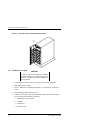
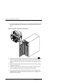
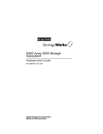
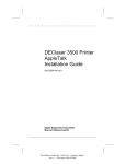
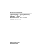
RAID Array 3000 Storage
Subsystem Second Controller
Option
Installation Guide
EK–SM3KC–IG. A01
Digital Equipment Corporation
Maynard, Massachusetts
First Edition, January, 1998
The disclosure of this information does not grant to the user a license under any patents,
pending patents, trademarks, or copyrights or other rights of Digital Equipment
Corporation, or of any third party.
This software is proprietary to and embodies the confidential technology of Digital
Equipment Corporation.
Possession, use or copying of the software described in this publication is authorized
only pursuant to a valid written license from Digital Equipment Corporation or an
authorized sublicensor.
Digital Equipment Corporation makes no representation that the use of its products in
the manner described in this publication will not infringe on existing or future patent
rights, nor do the descriptions contained in this publication imply the granting of
licenses to make, use, or sell equipment or software in accordance with the description.
UNIX is a registered trademark in the United States and other countries, licensed
exclusively through X/Opin Company, Ltd.
All other trademarks and registered trademarks are the property of their respective
owners.
The following are trademarks of Digital Equipment Corporation:
DEC, DIGITAL, RAID Array 3000, StorageWorks, and the DIGITAL Logo.
©Digital Equipment Corporation 1998.
Printed in USA
All Rights Reserved
Contents
Revision Record ............................................................................................... v
About This Guide ........................................................................................... vi
1
Second Controller Option
1.0
Introduction............................................................................................................ 1–1
2.0
Installation Procedure............................................................................................. 1–2
Figures
1–1
1–2
1–3
1–4
Second Controller Pedestal Slot Location ...................................................1–2
Insert Module into SIMM Connector ..........................................................1–3
Pivot Module Down to Seat ........................................................................1–3
Remove Controller from Top Slot...............................................................1–4
EK–SM3KC–IG. A01
iii
Revision Record
This Revision Record provides a concise publication history of this guide. It lists the
revision levels, release dates, and a summary of changes.
The following revision history lists all revisions of this publication and their effective
dates. The publication part number is included in the Revision Level column, with the
last entry denoting the latest revision. This publication supports the installation of the
Second Controller Option into the StorageWorks RAID Array 3000 Pedestal Enclosure.
Revision Level
EK–SM3KC–IG. A01
EK–SM3KC–IG. A01
Date
January, 1998
Summary of Changes
Original release.
v
About This Guide
This section identifies the audience of this guide. It also describes its contents and
includes a list of associated documents and the conventions.
Intended Audience
This guide is intended for installers and operators of the RAID Array 3000
storage subsystem. Installing the subsystem and its options requires a general
understanding of basic SCSI terminology and product installation procedures.
Document Structure
This guide contains the following section:
Chapter 1 Second Controller Option
1.0 Introduction – summarizes the content of this guide.
2.0 Installation Procedure – includes the steps required to install the second
controller option into the pedestal enclosure.
EK–SM3KC–IG. A01
vii
RAID Array 3000 Second Controller Option
Associated Documents
In addition to this guide, the following documentation is useful to the reader:
Table 1 Associated Documents
Document Title
Order Number
StorageWorks RAID Array 3000 Storage Subsystem
Hardware User’s Guide
StorageWorks RAID Array 3000 Configuration and
Maintenance Guide
Installation Instructions for the RAID Array
Replacement Controller – SWXRC-03
EK–SMCPO–UG
EK–SMCS2–UG
EK–SMCPL–PN
Conventions
Table 2 Style Conventions
Style
viii
Meaning
plain monospace
type
Text
boldface type
For the first instance of terms being
defined in text, or both.
italic type
For emphasis, manual titles, chapter
summaries, keyboard key names.
EK–SM3KC–IG. A01
About This Guide
Support and Services
Who to contact in the Americas
Information and Product Questions:
Local Sales Office / StorageWorks Hotline
1-800-786-7967
Installation Support:
Contact the DIGITAL Distributor where the
Storage Solution was Purchased / Local Digital
Sales Office.
DIGITAL Multivendor Customer Service (MCS):
Installation
Contact the DIGITAL Customer Support Center
(CSC).
Warranty
Contact the DIGITAL Customer Support Center
(CSC) for warranty service after solution is
installed and operating.
Remedial
Contact the DIGITAL Customer Support Center
(CSC)
Note: A Service Contract is recommended when
the equipment is out of warranty. Contact the
local DIGITAL Sales Office.
Customer Support Center (CSC)
1 800-354-9000
Who to contact in Europe
Information and Product Questions: Contact the DIGITAL Distributor or reseller
Installation Support and Installation: Contact the DIGITAL Distributor or reseller from
whom the Storage Solution was purchased.
For Warranty Service
See the Warranty Card packaged with the
product.
For Remedial Service
Contact the DIGITAL Distributor or reseller from
whom the Storage Solution was purchased.
Note: A Service Contract is recommended
when the equipment is out of warranty.
Who to contact in Asia Pacific
For all services, contact the DIGITAL Distributor or reseller from whom the
equipment was purchased
EK–SM3KC–IG. A01
ix
1
Second Controller Option
This guide describes how to install a second RAID controller in the pedestal. The second
controller option adds a fail/safe feature to your storage subsystem. The redundant controller is installed directly below the existing controller.
1.0
Introduction
The controller option provides a second (redundant) controller unit in your subsystem installation to preserve the integrity of data should the first controller
sustain a malfunction. The second controller is installed directly below the existing device in the bottom controller slot of the pedestal (see Figure 1-1).
The installation procedure consists of adding two SIMM memory modules to the
redundant controller and one memory module to the existing controller in the
pedestal. Following the memory upgrade, you simply insert and seat the devices
in their respective controller slots and configure the subsystem to accommodate a
redundant controller. The following steps summarize the option installation procedure:
•
Ensure the SCSI bus is quiescent prior to powering off the host, the pedestal,
and the UPS
•
Install two of the SIMM modules supplied with the kit into the second controller (all SIMMs must have the same memory capacity)
•
Install the third SIMM module supplied with the kit into the existing controller
•
Install the controllers into their appropriate slots in the pedestal
•
Power up the subsystem and configure the second controller for redundant
controller operation
EK–SM3KC–IG. A01
1–1
RAID Array 3000 Pedestal Enclosure
Figure 1–1 Second Controller Pedestal Slot Location
S econ d
C on tro lle r
S lo t
30 00 -48
2.0
Installation Procedure
CAUTION
To prevent an electrical discharge from damaging
the SIMMs, always wear an ESD wrist strap connected to a suitable ground when handling the
memory modules.
1–2
1.
Ensure that the UltraSCSI bus is in a quiescent state (no I/O activity).
2.
Shut down the host system.
3.
Issue a “shutdown” command from the SWCC console to the pedestal controller.
4.
Power off the pedestal(s) and the UPS.
5.
Perform an inventory of the items contained in the second controller kit option. The kit should contain the following:
•
RAID Array 3000 controller
•
3 SIMMs
•
Model label
•
Warranty Card
EK–SM3KC–IG. A01
Second Controller Option
6.
Install two of the SIMM modules into the second controller (make sure all
modules are of the same type) by aligning the connector pins and inserting
the modules into the SIMM module connectors as shown in Figure 1-2.
Figure 1–2 Insert Module into SIMM Connector
7.
Ensure the module is firmly seated and then gently pivot it toward the controller board until it snaps into place as shown in Figure 1-3.
Figure 1–3 Pivot Module Down to Seat
EK–SM3KC–IG. A01
1–3
RAID Array 3000 Pedestal Enclosure
8.
Remove the existing controller (Figure 1-4) and install the third module into
the empty SIMM connector using the same procedure described in steps 6
and 7.
Figure 1–4 Remove Controller from Top Slot
9.
Replace the existing controller into the top controller slot in the pedestal and
seat it into place by pushing forward on the side quick-disconnect handles.
Make sure the guides on each side of the controller align with the guides in
the slot.
10. Remove the dummy filler panel from the bottom controller slot by pulling
the handle straight out.
11. Install the second controller into the bottom controller slot and seat it into
place by pushing forward on the side quick-disconnect handles.
12. Power up the subsystem and refer to the RAID Array 3000 Configuration
and Maintenance Guide for information describing how to configure the redundant controller option.
1–4
EK–SM3KC–IG. A01
Reader’s Comments
Manual Order Number:
EK–SM3KC–IG. A01
RAID Array 3000 Second Controller Option Installation Guide
Digital is committed to providing the best possible products and services. Since our manuals are
important components of our products, we value your comments, corrections, and suggestions
for improvements. Please take a few minutes to fill out and return this form, attaching additional
sheets, if needed. Thank you.
Manual Rating
Excellent
Good
Fair
Poor
Accuracy (correct presentation of facts)
Completeness (adequate information)
Clarity (easy to understand)
Organization (logical sequence of information)
Layout (easy to follow subject matter)
Indexing (easy to locate desired information)
[
[
[
[
[
[
[
[
[
[
[
[
[
[
[
[
[
[
[
[
[
[
[
[
]
]
]
]
]
]
]
]
]
]
]
]
]
]
]
]
]
]
Errors Noted (please include page, paragraph, table or figure number)
Return Address:
Name
Customer Research
Title
Phone
Response Center
Digital Equipment Corporation
334 South Street, SHR3-2/S27
Company
Street Address
Shrewsbury, MA 01545
Mail Stop
City
Country (if other than USA)
State
ZIP
]
]
]
]
]
]