1
R
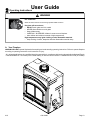
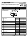
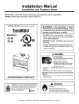
7100FP
EPA CERTIFIED WOODBURNING FIREPLACE
Owner’s Manual
Installation and Operation
Model:
7100FP-BK-B
7100FP-GD-B
7100FP-NL-B
Tested and
Listed by
O-T L
C
Portland
Oregon USA
US
OMNI-Test Laboratories, Inc.
CAUTION
DO NOT DISCARD THIS MANUAL
• Important operating
and maintenance
instructions included.
• Read, understand and
follow these instructions
for safe installation and
operation.
• Leave this manual with
party responsible for
use and operation.
WARNING
WARNING
If the information in these instructions is not followed exactly, a
fire may result causing property
damage, personal injury, or death.
• Do not store or use gasoline or other flammable vapors and liquids in the vicinity of this
or any other appliance.
• Do not overfire - If heater or chimney connector glows, you are overfiring. Overfiring will
void your warranty.
• Comply with all minimum clearances to combustibles as specified. Failure to comply may
cause house fire.
Installation and service of this appliance should be
performed by qualified personnel. Hearth & Home
Technologies recommends NFI certified professionals, or technicians supervised by an
NFI certified professional.
D
DI O N
SC O
AR T
D
HOT SURFACES!
Glass and other surfaces are
hot during operation AND
cool down.
Hot glass will cause burns.
• Do not touch glass until it is cooled
• NEVER allow children to touch glass
• Keep children away
• CAREFULLY SUPERVISE children in the same room
as appliance
• Alert children and adults to hazards of high
temperatures
High temperatures may ignite clothing or other
flammable materials.
• Keep clothing, furniture, draperies and other
combustibles away.
WARNING
Fire Risk.
For use with solid wood fuel only.
Other fuels may overfire and generate
poisonous gases (i.e. carbon monoxide).
Read this manual before installing or operating this appliance.
Please retain this owner’s manual for future references.
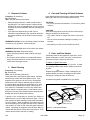
Congratulations
Congratulations on selecting a Quadra-Fire wood burning
fireplace. The Quadra-Fire fireplace you have selected is
designed to provide the utmost in safety, reliability, and
efficiency.
This Owner's Manual should be retained for future
reference. We suggest that you keep it with your other
important documents and product manuals.
Your new Quadra-Fire wood burning fireplace will give you
years of durable use and trouble-free enjoyment. Welcome
to the Quadra-Fire family of fireplace products!
As the owner of a new fireplace, you'll want to read and
carefully follow all of the instructions contained in this
Owner's Manual. Pay special attention to all Cautions and
Warnings.
Homeowner Reference Information
We recommend that you record the following pertinent
information about your appliance.
Model Name: ___________________________________________ Date purchased/installed: __________________
Serial Number:__________________________________________ Location on appliance: ____________________
Dealership purchased from: _______________________________ Dealer Phone: __________________________
Notes: _______________________________________________________________________________________
_____________________________________________________________________________________________
The model information regarding your specific appliance can
be found on the rating plate usually located in the control
area of the appliance.
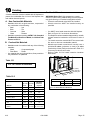
Listing Label Information/Location
Model:
R
Tested and
Listed by
O-T L
C
Portland
Oregon USA
US
OMNI-Test Laboratories, Inc.
Report #061-S-41-2
TESTED TO:
UL 127, ULC-S610-M87
A division of Hearth & Home Technologies Inc.
1915 W. Saunders St. Mt. Pleasant, IA 52641
www.quadrafire.com
7100FP
EPA CERTIFIED FIREPLACE
Serial No / Numéro De Série
009
Minimum Clearances To Combustible Material
LISTED FIREPLACE, SOLID FUEL TYPE, ALSO SUITABLE FOR Manufactured
HOME INSTALLATION. (UM) 84 HUD. "For Use with Solid Wood Fuel Only."
SA
M
PL
E
Install and use only in accordance with manufacturer's installation, venting and operating instructions.
Any area incorporating warm or cold air ducts shall be enclosed in accordance with the manufacturer's
installation instructions.
Contact Your Local Building Or Fire Officials Or Authority Having Jurisdiction About Restrictions,
Installation Inspection And Permits Required In Your Area.
WARNING - For Maufactured Homes: Do not install in a sleeping room. An outside combustion air
inlet must be provided and unrestricted while unit is in use. The structural integrity of the manufactured
home floor, ceiling and walls must be maintained. The fireplace needs to be properly grounded to the
frame of the manfactured home.
Components required for installation: HTI SLSeries Pipe or Dura Plus System, Termination Cap, Hearth
Extension and required accessory Chimney Air Kit Part CAK4A.
Do not connect this unit to a chimney serving another appliance.
DANGER: Risk of electrical shock. Disconnect power supply before servicing.
Electrical Rating: 115 VAC <3.0 AMPS 60 Hz
Do not use grate or elevate fire. Build wood fire directly on firebrick.
Do not overfire. If heater or chimney connector glows, you are overfiring.
Do not use a fireplace insert or other products not specified for use with this product.
WARNING - THIS FIREPLACE HAS NOT BEEN TESTED WITH AN UNVENTED GAS LOG SET OR ANY LOG SET.
TO REDUCE RISK OF FIRE OR INJURY, DO NOT INSTALL AN UNVENTED GAS LOG SET OR ANY LOG SET
INTO FIREPLACE.
Must provide a source of air to prevent air starvation from combustion which could result of high levels
of carbon monoxide.
Replace glass only with 5mm ceramic available from your dealer.
Optional Fire Screen Part Mesh-EPA, may be used ONLY in USA
Chimney sections at any level require a 2” (51mm) minimum
air space clearance between the framing and chimney section.
WITHIN ENCLOSURE AREA
Appliance to backwall
1/2" (13mm)
Appliance to sidewall
1" (25mm)
Duct boots to framing
0" (0mm)
Top standoffs to header
0" (0mm")
Product covered by US Patents 4,766,876; 5,113,843; 5,341,794
Patent pending
EXPOSED SURFACES
Faceplate to sidewall
Remote outlet air grills to ceiling
MANTEL
Mantel from base of fireplace
Maximum mantel depth
16" (406mm)
12" (305mm)
60" (1524mm)
12" (305mm)
FLOOR PROTECTION
Combustible flooring 20" (508mm) in front of and 8" (203mm) to
either side of the fuel opening must be insulated with
non-combustible floor protection with a minimum thickness of 1"
(25mm) and ("k" value = 0.43).
In Canada: The hearth extension must be installed according to
the installation instructions.
U.S. ENVIRONMENTAL PROTECTION AGENCY - Certified to comply with July 1990 particulate emission standards.
2011 2012 2013 Jan Feb Mar Apr May June July Aug Sept Oct. Nov. Dec.
Mfg by:
DO NOT REMOVE THIS LABEL
Page 2
Made in U.S.A
433-1390K
433-1400
4/12
Safety Alert Key:
•
•
•
•
DANGER! Indicates a hazardous situation which, if not avoided will result in death or serious injury.
WARNING! Indicates a hazardous situation which, if not avoided could result in death or serious injury.
CAUTION! Indicates a hazardous situation which, if not avoided, could result in minor or moderate injury.
NOTICE: Indicates practices which may cause damage to the fireplace or to property.
Table of Contents
C. Draft . . . . . . . . . . . . . . . . . . . . . . . . . . . . . . . . . . . . . . 32
D. Negative Pressure . . . . . . . . . . . . . . . . . . . . . . . . . . . 32
E. Locating Fireplace & Chimney . . . . . . . . . . . . . . . . . . 33
F. Tools and Supplies Needed. . . . . . . . . . . . . . . . . . . . 34
G. Fireplace System Requirements. . . . . . . . . . . . . . . . 34
H. Inspect Fireplace and Components. . . . . . . . . . . . . . 34
LIMITED LIFETIME WARRANTY. . . . . . . . . . . . . . . . . . . . 4
1
2
3
Listing and Code Approvals
A. Appliance Certification . . . . . . . . . . . . . . . . . . . . . . . . . 6
B. Manufactured Home Approved . . . . . . . . . . . . . . . . . . 6
C. BTU & Efficiency Specifications. . . . . . . . . . . . . . . . . . 7
D. Non-Combustible Materials. . . . . . . . . . . . . . . . . . . . . 7
E. Combustible Materials. . . . . . . . . . . . . . . . . . . . . . . . . 7
F. Electrical Codes. . . . . . . . . . . . . . . . . . . . . . . . . . . . . . 7
G. Glass Specifications. . . . . . . . . . . . . . . . . . . . . . . . . . . 7
Operating Instructions
A. Your Fireplace . . . . . . . . . . . . . . . . . . . . . . . . . . . . . . . 8
B. General Information. . . . . . . . . . . . . . . . . . . . . . . . . . . 9
C. Baffle and Blanket Placement. . . . . . . . . . . . . . . . . . . 9
D. Firebrick Placement. . . . . . . . . . . . . . . . . . . . . . . . . . . 9
E. Wood Fuel. . . . . . . . . . . . . . . . . . . . . . . . . . . . . . . . . 10
F. Outside Air . . . . . . . . . . . . . . . . . . . . . . . . . . . . . . . . . 11
G. Clear Space Near the Fireplace . . . . . . . . . . . . . . . . 12
H. Glass Doors. . . . . . . . . . . . . . . . . . . . . . . . . . . . . . . . 12
I. Fan Operation . . . . . . . . . . . . . . . . . . . . . . . . . . . . . . 12
J. Fire Safety . . . . . . . . . . . . . . . . . . . . . . . . . . . . . . . . . 13
K. Over-Firing Your Appliance . . . . . . . . . . . . . . . . . . . . 13
L. Chimney Fire . . . . . . . . . . . . . . . . . . . . . . . . . . . . . . . 13
M. Starting a Fire. . . . . . . . . . . . . . . . . . . . . . . . . . . . . . 14
N. Burning Process . . . . . . . . . . . . . . . . . . . . . . . . . . . . 14
O. Automatic Combustion Control (ACC). . . . . . . . . . . . 15
P. ACC Override. . . . . . . . . . . . . . . . . . . . . . . . . . . . . . . 15
Q. Auxiliary Convertion Air System. . . . . . . . . . . . . . . . . 16
R. Burning Guidelines . . . . . . . . . . . . . . . . . . . . . . . . . . 16
S. Burn Rates. . . . . . . . . . . . . . . . . . . . . . . . . . . . . . . . . 16
T. Opacity. . . . . . . . . . . . . . . . . . . . . . . . . . . . . . . . . . . . 16
Troubleshooting
6
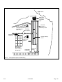
Framing and Clearances
7
Installation of Fireplace
8
Chimney Assembly
9
Chase Installations
A. Understanding Vent Problems . . . . . . . . . . . . . . . . . .17
B. Draft Problems. . . . . . . . . . . . . . . . . . . . . . . . . . . . . . 17
C. Diagnostics and Problem Solving. . . . . . . . . . . . . . . 19
4
Maintenance and Servicing the Fireplace
A. General Maintenance. . . . . . . . . . . . . . . . . . . . . . . . . 21
1. Creosote (Chimney) Cleaning . . . . . . . . . . . . . . . 21
2. Disposal of Ashes. . . . . . . . . . . . . . . . . . . . . . . . . 22
3. Glass Cleaning. . . . . . . . . . . . . . . . . . . . . . . . . . . 22
4. Care and Cleaning of Plated Surfaces. . . . . . . . . 22
5. Door and Door Gasket . . . . . . . . . . . . . . . . . . . . 22
6. Maintenance Task List. . . . . . . . . . . . . . . . . . . . . 23
B. Replacement Maintenance . . . . . . . . . . . . . . . . . . . . 23
1. Glass Replacement . . . . . . . . . . . . . . . . . . . . . . . 23
2. Firebrick Replacement. . . . . . . . . . . . . . . . . . . . . 24
3. Baffle Removal and Installation. . . . . . . . . . . . . . 25
4. Fan Replacement. . . . . . . . . . . . . . . . . . . . . . . . . 25
5. Timer Assembly Replacement. . . . . . . . . . . . . . . 26
6. Timer Removal & Replacement. . . . . . . . . . . . . . . . 28
A. Secure the Fireplace. . . . . . . . . . . . . . . . . . . . . . . . . 39
B. Place Protective Metal Hearth Strips. . . . . . . . . . . . . 39
C. Install the Outside Air Kit. . . . . . . . . . . . . . . . . . . . . . 39
D. Auxiliary Convection Air System. . . . . . . . . . . . . . . . . 41
E. Auxiliary Convection Air Lever . . . . . . . . . . . . . . . . . . 42
A. Chimney Requirements. . . . . . . . . . . . . . . . . . . . . . . 44
B. Chimney Termination Requirements. . . . . . . . . . . . . 44
C. Using Offsets/ Returns. . . . . . . . . . . . . . . . . . . . . . . . 45
D. Assemble the Chimney Sections. . . . . . . . . . . . . . . . 46
E. Installing CAK4A and Flex Pipe. . . . . . . . . . . . . . . . . 46
F. Install Ceiling Firestops . . . . . . . . . . . . . . . . . . . . . . . 47
G. Install Attic Insulation Shield . . . . . . . . . . . . . . . . . . . 48
H. Secure the Chimney . . . . . . . . . . . . . . . . . . . . . . . . . 48
I. Double-check the Chimney Assembly. . . . . . . . . . . . 49
J. Cut out Hole in Roof. . . . . . . . . . . . . . . . . . . . . . . . . . 49
K. Complete Installation. . . . . . . . . . . . . . . . . . . . . . . . . 49
L. Install Flashing. . . . . . . . . . . . . . . . . . . . . . . . . . . . . . 49
M. Chimney Termination Requirements. . . . . . . . . . . . . 50
N. SL-300 Series Ceiling/Roof Thimble. . . . . . . . . . . . . . 51
A. Construct the Chase . . . . . . . . . . . . . . . . . . . . . . . . . 52
B. Install Fireplace & Chimney. . . . . . . . . . . . . . . . . . . . 53
C. Install Chase Top. . . . . . . . . . . . . . . . . . . . . . . . . . . . 53
D. Install Termination Cap . . . . . . . . . . . . . . . . . . . . . . . 53
10 Finishing
A. Non-Combustible Materials. . . . . . . . . . . . . . . . . . . . 55
B. Combustible Materials. . . . . . . . . . . . . . . . . . . . . . . . 55
C. Hearth Extension. . . . . . . . . . . . . . . . . . . . . . . . . . . . 55
D. Position the Hearth Extension. . . . . . . . . . . . . . . . . . 57
E. Finishing Material. . . . . . . . . . . . . . . . . . . . . . . . . . . . 57
F. Mantel. . . . . . . . . . . . . . . . . . . . . . . . . . . . . . . . . . . . . 58
G. Non-Combustible Facing Material Installation. . . . . . 59
11 Accessories
A. Heat Zone Kit (Optional) . . . . . . . . . . . . . . . . . . . . . . 60
B. Firescreen . . . . . . . . . . . . . . . . . . . . . . . . . . . . . . . . . 63
C. Fascia (Fronts) . . . . . . . . . . . . . . . . . . . . . . . . . . . . . 63
12 Reference Materials
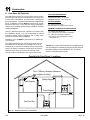
5 Getting Started
A. Typical Fireplace System. . . . .. . . . . . . . . . . . . . . . . 31
B. Design and Installation Considerations. . . . . . . . . . . 32
4/12
A. Selecting Fireplace Locations . . . . . . . . . . . . . . . . . . 35
B. Clearances . . . . . . . . . . . . . . . . . . . . . . . . . . . . . . . . 36
C. Frame the Fireplace. . . . . . . . . . . . . . . . . . . . . . . . . . 37
D. Electrical Access and Wiring Diagram. . . . . . . . . . . . 38
433-1390K
A. Fireplace Dimensions . . . . . . . . . . . . . . . . . . . . . . . . 64
B. Chimney Components. . . . . . . . . . . . . . . . . . . . . . . . 67
C. Service Parts. . . . . . . . . . . . . . . . . . . . . . . . . . . . . . . 70
D. Contact Information. . . . . . . . . . . . . . . . . . . . . . . . . . 75
Page 3
Hearth
& Home
Technologies
Inc. Inc
Hearth
& Home
Technologies
LIMITED
LIFETIME
WARRANTY
LIMITED LIFETIME WARRANTY
Hearth & Home Technologies Inc., on behalf of its hearth brands (”HHT”), extends the following warranty for
HHT gas, wood, pellet, coal and electric hearth appliances that are purchased from an HHT authorized dealer.
WARRANTY COVERAGE:
HHT warrants to the original owner of the HHT appliance at the site of installation, and to any transferee taking ownership
of the appliance at the site of installation within two years following the date of original purchase, that the HHT appliance
will be free from defects in materials and workmanship at the time of manufacture. After installation, if covered components manufactured by HHT are found to be defective in materials or workmanship during the applicable warranty period,
HHT will, at its option, repair or replace the covered components. HHT, at its own discretion, may fully discharge all of its
obligations under such warranties by replacing the product itself or refunding the verified purchase price of the product
itself. The maximum amount recoverable under this warranty is limited to the purchase price of the product. This warranty
is subject to conditions, exclusions and limitations as described below.
WARRANTY PERIOD:
Warranty coverage begins on the date of original purchase. In the case of new home construction, warranty coverage
begins on the date of first occupancy of the dwelling or six months after the sale of the product by an independent,
authorized HHT dealer/ distributor, whichever occurs earlier. The warranty shall commence no later than 24 months
following the date of product shipment from HHT, regardless of the installation or occupancy date. The warranty period for
parts and labor for covered components is produced in the following table.
The term “Limited Lifetime” in the table below is defined as: 20 years from the beginning date of warranty coverage for
gas appliances, and 10 years from the beginning date of warranty coverage for wood, pellet, and coal appliances. These
time periods reflect the minimum expected useful lives of the designated components under normal operating conditions.
Warranty Period
Parts
Labor
1 Year
2 years
HHT Manufactured Appliances and Venting
Gas
X
X
Wood
X
X
X
3 years
Pellet
EPA
Wood
Coal
X
X
X
X
X
X
X
X
X
Components Covered
Electric Venting
X
X
All parts and material except as
covered by Conditions,
Exclusions, and Limitations
listed
Igniters, electronic components,
and glass
Factory-installed blowers
Molded refractory panels
X
Firepots and burnpots
5 years
1 year
7 years
3 years
10
years
1 year
X
Limited
3 years
Lifetime
X
X
X
X
X
90 Days
X
X
X
X
X
X
X
X
Castings and baffles
X
X
Manifold tubes,
HHT chimney and termination
Burners, logs and refractory
Firebox and heat exchanger
X
X
All replacement parts
beyond warranty period
See conditions, exclusions, and limitations on next page.
4021-645C 12-29-10
4/12
Page 1 of 2
433-1390K
Page 4
WARRANTY CONDITIONS:
•
•
•
•
This warranty only covers HHT appliances that are purchased through an HHT authorized dealer or distributor. A list of
HHT authorized dealers is available on the HHT branded websites.
This warranty is only valid while the HHT appliance remains at the site of original installation.
Contact your installing dealer for warranty service. If the installing dealer is unable to provide necessary parts, contact
the nearest HHT authorized dealer or supplier. Additional service fees may apply if you are seeking warranty service
from a dealer other than the dealer from whom you originally purchased the product.
Check with your dealer in advance for any costs to you when arranging a warranty call. Travel and shipping charges
for parts are not covered by this warranty.
WARRANTY EXCLUSIONS:
This warranty does not cover the following:
• Changes in surface finishes as a result of normal use. As a heating appliance, some changes in color of interior and
exterior surface finishes may occur. This is not a flaw and is not covered under warranty.
• Damage to printed, plated, or enameled surfaces caused by fingerprints, accidents, misuse, scratches, melted items,
or other external sources and residues left on the plated surfaces from the use of abrasive cleaners or polishes.
• Repair or replacement of parts that are subject to normal wear and tear during the warranty period. These parts
include: paint, wood, pellet and coal gaskets, firebricks, grates, flame guides, light bulbs, batteries and the discoloration of glass.
• Minor expansion, contraction, or movement of certain parts causing noise. These conditions are normal and complaints related to this noise are not covered by this warranty.
• Damages resulting from: (1) failure to install, operate, or maintain the appliance in accordance with the installation
instructions, operating instructions, and listing agent identification label furnished with the appliance; (2) failure to
install the appliance in accordance with local building codes; (3) shipping or improper handling; (4) improper operation, abuse, misuse, continued operation with damaged, corroded or failed components, accident, or improperly/
incorrectly performed repairs; (5) environmental conditions, inadequate ventilation, negative pressure, or drafting
caused by tightly sealed constructions, insufficient make-up air supply, or handling devices such as exhaust fans or
forced air furnaces or other such causes; (6) use of fuels other than those specified in the operating instructions; (7)
installation or use of components not supplied with the appliance or any other components not expressly authorized
and approved by HHT; (8) modification of the appliance not expressly authorized and approved by HHT in writing;
and/or (9) interruptions or fluctuations of electrical power supply to the appliance.
• Non-HHT venting components, hearth components or other accessories used in conjunction with the appliance.
• Any part of a pre-existing fireplace system in which an insert or a decorative gas appliance is installed.
• HHT’s obligation under this warranty does not extend to the appliance’s capability to heat the desired space. Information is provided to assist the consumer and the dealer in selecting the proper appliance for the application. Consideration must be given to appliance location and configuration, environmental conditions, insulation and air tightness of
the structure.
This warranty is void if:
•
•
•
The appliance has been over-fired or operated in atmospheres contaminated by chlorine, fluorine, or other damaging
chemicals. Over-firing can be identified by, but not limited to, warped plates or tubes, rust colored cast iron, bubbling,
cracking and discoloration of steel or enamel finishes.
The appliance is subjected to prolonged periods of dampness or condensation.
There is any damage to the appliance or other components due to water or weather damage which is the result of, but
not limited to, improper chimney or venting installation.
LIMITATIONS OF LIABILITY:
•
The owner’s exclusive remedy and HHT’s sole obligation under this warranty, under any other warranty, express or
implied, or in contract, tort or otherwise, shall be limited to replacement, repair, or refund, as specified above. In no
event will HHT be liable for any incidental or consequential damages caused by defects in the appliance. Some states
do not allow exclusions or limitation of incidental or consequential damages, so these limitations may not apply to you.
This warranty gives you specific rights; you may also have other rights, which vary from state to state. EXCEPT TO
THE EXTENT PROVIDED BY LAW, HHT MAKES NO EXPRESS WARRANTIES OTHER THAN THE WARRANTY
SPECIFIED HEREIN. THE DURATION OF ANY IMPLIED WARRANTY IS LIMITED TO DURATION OF THE
EXPRESSED WARRANTY SPECIFIED ABOVE.
4/12
4021-645C 12-29-10
433-1390K
Page 5
Page 2 of 2
1
Listing and Code Approvals
A. Appliance Certification
This fireplace system has been tested and listed in
accordance with UL127 and ULC-S610-M87 and (UM)84HUD standards, and has been listed by OMNI Test
Laboratories, Inc., for installation and operation in the
United States and Canada as described in this manual. This fireplace has been tested and listed for use with the
SL-300 Series chimney (with the the CAK4A Air Kit) and
fireplace components listed in Section 12. The Dura-Plus
is also an approved venting system manufactured by DuraVent Systems.
Check with your local building code agency before you begin
your installation to ensure compliance with local codes,
including the need for permits and follow-up inspections. Be sure local building codes do not supersede UL specifications and always obtain a building permit so that insurance
protection benefits cannot be unexpectedly cancelled. Quadrafire is a registerd trademark of Hearth & Home Technologies Inc.
Model:
7100FP EPA Certified
Woodburning Fireplace
Laboratory:
OMNI Test Laboratories, Inc.
Report No:
061-S-41-2
Type:
Wood Fireplace
Standard:
UL127 and ULC-S610-M87 and
(UM) 84-HUD, Manufactured Home
Approved.
1.An outside air inlet must be provided for combustion and
must remain clear of leaves, debris, ice and/or snow. It
must be unrestricted while unit is in use to prevent room
air starvation which can cause smoke spillage and an
inability to maintain a fire. Smoke spillage can also set
off smoke alarms.
2.The fireplace is to be secured to the manufactured home
structure. Use same holes that attached the fireplace to
the pallet to secure it to the floor using 1/4 in. x 2 in. (6
mm x 51 mm) lag bolts or equivalent.
3.Unit must be grounded with #8 solid copper grounding
wire or equivalent and terminated at each end with N.E.C.
approved grounding device.
4.Refer to Minimum Clearances to Combustibles on pages
36-37 and chimney components on pages 64-65
5.Floor protections requirements on pages 54-56 must be
followed precisely.
6.Use silicone to create an effective vapor barrier at
the location where the chimney or other component
penetrates to the exterior of the structure.
7.If unit burns poorly while an exhaust fan is on in home,
(i.e., range hood), increase combustion air.
NOTICE: Top sections of chimney must be removable
to allow maximum clearance of 13.5 ft (411 cm) from
ground level for transportation purposes.
Warning! Risk of Fire or Asphyxiation!
DO NOT install in sleeping room
Warning! Risk of Fire! Improper installation of wood inserts may cause fireplace or chimney system to overheat.
B. Manufactured Home Approved
This appliance is approved for manufactured home installations when not installed in a sleeping room and when
an outside combustion air inlet is provided. THE STRUCTURAL INTEGRITY OF THE MANUFACTURED HOME
FLOOR, CEILING, AND WALLS MUST BE MAINTAINED. The fireplace must be properly grounded to the frame of
the manufactured home. Outside Air must be installed in a
manufactured home installation.
An outside air termination cap is supplied with your
7100FP Fireplace for installation in a manufactured home. If you use an alternative material it must be designed to
prevent material from dropping into the area beneath the
manufactured home, and to prevent rodents from entering
from the outside.
4/12
Caution! Maintain structural intergrity of manufactured
home:
• Floor, wall, ceiling and /or roof.
• Any supporting materal that would affect the structural
integrity.
• Do NOT cut through:
Floor joist, wall, studs or ceiling trusses.
Warning! Risk of Fire!
For use with solid wood fuel only.
Other fuels may overfire and generate
poisonous gases (i.e. carbon monoxide).
NOTICE: Hearth & Home Technologies, manufacturer
of this appliance, reserves the right to alter its products,
their specifications and/or price without notice.
433-1390K
Page 6
C. BTU & Efficiency Spectifications
EPA# and Original Date:
#571 4-1-03
EPA Certified:
3.1 grams per hour
Efficiency:
up to 77%
WARNING! Improper installation, adjustment, alteration, service or maintenance can cause injury or property damage. Refer to the owner’s information manual
provided with this fireplace. For assistance or additional
information consult a qualified installer, service agency
or your dealer.
BTU Output
with EPA test fuel:
58,000 / hr.
with Cord Wood:
90,000 / hr.
Heating Capacity:
up to 3,500 sq ft
Vent Size:
8 inches
Max Wood Length:
24 inches
Fuel:
Cord Wood
Shipping Weight:
670 lbs
Firebox Size
3.7 cubic feet
G. Glass Specifications
This fireplace is equipped with 5mm ceramic glass. Replace
glass only with 5mm ceramic glass. Please contact your
dealer for replacement glass.
D. Non-Combustible Materials
• Materials which will not ignite and burn, composed of
any combination of the following:
- Steel
- Iron
- Brick
- Tile
- Concrete
- Slate
- Glass
- Plasters
• Materials reported as passing ASTM E 136, Standard
Test Method for Behavior of Metals, in a Vertical Tube
Furnace at 750° C
E. Combustible Materials
• Materials made of or surfaced with any of the following
materials:
- Wood
- Compressed paper
- Plant fibers - Plastic
• Any material that can ignite and burn; flame proofed or
not, plastered or un-plastered
F. Electrical Codes
NOTICE: This appliance must be electrically wired
and grounded in accordance with local codes or, in the
absence of local codes, with National Electric Code ANSI/
NFPA 70-latest edition or the Canadian Electric Code
CSA C22.1.
• A 110-120 VAC circuit for this product must be protected
with ground-fault circuit-interrupter protection, in
compliance with the applicable electrical codes, when
it is installed in damp locations.
NOTICE: This installation must conform with local codes. In
the absence of local codes you must comply with the UL127,
(UM) 84-HUD and NFPA211 in the U.S.A. and the ULC
610-M87 and CAN/CSA-B365 Installation Codes in Canada.
Warning! Risk of Fire! Hearth & Home Technologies
disclaims any responsibility for, and the warranty and
agency listing will be voided by the following actions.
DO NOT:
• install or operate damaged fireplace
• modify fireplace
• install other than as instructed by Hearth & Home
Technologies
• operate the fireplace without fully assembling all
components
• overfire
• install an unvented gas log set
• install any component not approved by Hearth & Home
Technologies
• install parts or components not Listed or approved
Improper installation, adjustment, alteration, service or
maintenance can cause injury or property damage. For
assistance or additional information, consult a qualified
installer, service agency or your dealer.
Electrical Codes are used only if the unit is supplied with
a fan.
4/12
433-1390K
Page 7
2
User Guide
Operating Instructions
WARNING
HOT SURFACES!
GlassandothersurfacesarehotduringoperationANDcooldown.
Hot glass will cause burns.
• DO NOTtouchglassuntilitiscooled
• NEVERallowchildrentotouchglass
• Keepchildrenaway
• CAREFULLYSUPERVISEchildreninsameroomasfireplace.
• Alertchildrenandadultstohazardsofhightemperatures.
High temperatures may ignite clothing or other flammable materials.
• Keepclothing,furniture,draperiesandotherflammablematerialsaway.
A. Your Fireplace
WARNING! DO NOT operate fireplace before reading and understanding operating instructions. Failure to operate fireplace
according to operating instructions could cause fire or injury.
ALLwiringshouldbedonebyaqualifiedelectricianandshallbeincompliancewithlocalcodesandwiththeNationalElectric
CodeNFPA/NECNo.70-current(intheUnitedStates),orwiththecurrentCSC22.1CanadianElectricCode(inCanada).
4/12
433-1390K
Page8
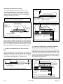
INCORRECT POSITIONS
B. General Information
Fireplaces, as well as other woodburning appliances, have
been used safely for many years. It has been our experience
that most problems are caused by improper installation and
operation of the fireplace. Make certain that installation and
operation of the fireplace system is in accordance with these
instructions.
It is extremely important that the fire be supervised whenever the fireplace is in use. It is also recommended that an
annual inspection be performed on the fireplace system to
determine if the flue system needs to be cleaned, or as in
the case of any appliance, if minor repairs are required to
maintain the system in top operating condition.
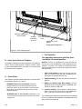
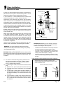
Ceramic Blanket and Baffle Board are NOT in
contact with the back of the firebox.
Warning! Risk of Fire! Keep combustible materials,
gasoline and other flammable vapors and liquids clear of
the fireplace.
Do NOT:
• store flammable materials close to the fireplace
• use gasoline, lantern fuel, kerosene, charcoal lighter
fluid or similar liquids to start or “freshen up” a fire in this
fireplace.
Ceramic Blanket is NOT in contact with the
back of the firebox and NOT even with the
Baffle Board in the front.
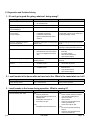
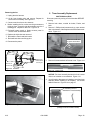
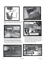
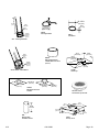
C. Baffle and Blanket Placement
Ceramic Blanket
Ensure correct baffle placement and replace baffle components if damaged or missing.
Firebox damage due to improper baffle placement is not
covered by warranty. Operate the wood burning appliance
with the baffle in the correct position only. Not doing so
could result in:
• Reduced efficiency
• Overheating the chimney
• Overheating the rear of the firebox
• Poor performance
Baffle Board
Ceramic Blanket is bunched up at the back of
the firebox and NOT even with the Baffle Board
in the front.
Figure
CeramicBlanket
Back of Firebox
2.3
BackofFirebox
D. Firebrick Placement
BaffleProtection
Channelinposition
Figure 2.2
BaffleBoard
Ceramic Blanket and Baffle Board MUST be in contact
with the back of the firebox and even with each other in
the front. Baffle Protection Channel MUST be in position.
4/12
The firebox of your fireplace is lined with high quality
firebrick, which has exceptional insulating properties. Do Not use a grate; simply build a fire on the firebox
floor. Do not operate the fireplace without bricks. Make
sure bricks are installed as shown in Section 4, page 24.
433-1390K
Page 9
E. Wood Fuel
Moisture content
Regardless of which species of wood you burn, the single
most important factor that affects the way your fireplace
Your fireplace’s performance depends a great deal on the operates is the amount of moisture in the wood. The majority
quality of the firewood you use. Contrary to popular belief, of the problems fireplace owners experience are caused by
one species of wood varies very little to the other in terms of trying to burn wet, unseasoned wood. Freshly cut wood can
energy content. All seasoned wood, regardless of species, be as much water as it is wood, having a moisture content of
contains about 8,000 BTU’s per pound. The important factor around 50%. Imagine a wooden bucket that weighs about 8
is that hardwoods have a greater density than softwoods. pounds. Fill it with a gallon of water, put it in the firebox and
Therefore, a piece of hardwood will contain about 60% more try to burn it. This sounds ridiculous but that is exactly what
BTU’s than an equal size piece of softwood. Since firewood you are doing if you burn unseasoned wood. Dead wood lying
is commonly sold by the cord (128 cu. ft) a volume measure- on the forest floor should be considered wet, and requires full
ment, a cord of seasoned oak (hardwood) would contain seasoning time. Standing dead wood can be considered to be
about 60% more potential energy than a cord of seasoned about two-thirds seasoned, if cut at the dry time of the year.
pine (softwood).
The problems with burning wet, unseasoned wood are two
There are many definitions of hardwood and softwood. fold. First, you will receive less heat output from wet wood
Although not true in every case, one of the most reliable because it requires energy in the form of heat to evaporate
is to classify them as coniferous or deciduous. Softwoods the water trapped inside. This is wasted energy that should be
are considered coniferous. These are trees with needle-like used for heating your home. Secondly, this moisture evapoleaves that stay green all year and carry their seeds exposed rates in the form of steam which has a cooling effect in your
in a cone. Examples of softwood trees are Douglas fir, pine, firebox and chimney system. When combined with tar and
spruce and cedar. Softwoods, being more porous, require other organic vapors from burning wood it will form creosote
less time to dry, burn faster and are easier to ignite than which condenses in the relatively cool firebox and chimney.
hardwoods. Deciduous trees are broadleaf trees that lose See the maintenance section of this manual for more infortheir leaves in the fall. Their seeds are usually found within a mation regarding creosote formation and need for removal.
protective pod or enclosure. Hardwoods fall into this category.
Some examples of deciduous trees are oak, maple, apple, Even dry wood contains at least 15% moisture by weight,
and birch. However, it should be noted that there are some and should be burned hot enough to keep the chimney hot
deciduous trees that are definitely not considered hardwoods for as long as it takes to dry the wood out - about one hour. such as poplar, aspen and alder. Hardwoods require more To tell if wood is dry enough to burn, check the ends of the
time to season, burn slower and are usually harder to ignite logs. If there are cracks radiating in all directions from the
than softwoods. Obviously, you will use the type of wood that center, it is dry. If your wood sizzles in the fire, even though
is most readily available in your area. However, if at all pos- the surface is dry, it may not be fully cured. sible the best arrangement is to have a mix of softwood and
hardwood. This way you can use the softwood for starting the
fire giving off quick heat to bring the appliance up to operating temperature. Then add the hardwood for slow, even heat
Seasoning
and longer burn time.
Hardwood vs. Softwood
Soft woods
Hard woods
•
•
•
•
•
•
•
•
•
•
•
Douglas Fir
Pine
Spruce
Cedar
Poplar
Aspen
Alder
Oak
Maple
Apple
Birch
Seasoned firewood is nothing more than wood that is cut
to size, split and air dried to a moisture content of around
20%. The time it takes to season wood varies from around
nine months for soft woods to as long as eighteen months
for hardwoods. The key to seasoning wood is to be sure it
has been split, exposing the wet interior and increasing the
surface area of each piece. A tree that was cut down a year
ago and not split is likely to have almost as high a moisture
content now as it did when it was cut.
Warning! Risk of Fire!
•
Do NOT burn wet or green wood.
•
Wet, unseasoned wood can cause accumulation of creosote.
4/12
433-1390K
Page 10
F. Outside Air
Seasoned Wood
• Cut logs to size
• Split to 6 in. (152 mm) or less
• Air dry to a moisture content of around 20%
- Soft wood - about nine months
- Hard wood - about eighteen months
Notice: Seasoning time may vary depending on drying
conditions.
Storing Wood
Splitting wood before it is stored reduces drying time. The
following guideline will ensure properly seasoned wood:
•
Stack the wood to allow air to circulate freely around and
through the woodpile.
•
Elevate the woodpile off the ground to allow air circulation underneath.
•
The smaller the pieces, the faster the drying process.
Any piece over 6 in. (152 mm in diameter should be split.
•
Wood should be stacked so that both ends of each piece
are exposed to air, since more drying occurs through the
cut ends than the sides. This is true even with wood that
has been split.
•
Store wood under cover, such as in a shed, or covered
with a tarp, plastic, tar paper, sheets of scrap plywood,
etc., as uncovered wood can absorb water from rain or
snow, delaying the seasoning process. Avoid covering
the sides and ends completely. Doing so may trap moisture from the ground and impede air circulation.
Warning! Fire Risk! DO NOT store wood:
• In front of the fireplace.
• In space required for loading or ash removal.
• Closer than required clearances to combustibles to
appliance
Do NOT operate appliance:
• With ash removal system door open.
• With appliance door open.
A source of air (oxygen) is required in order for combustion
to take place. Whatever air is consumed by the fire must be
replaced through cracks around windows, under doors, etc.
Most newly constructed houses or existing homes fitted with
tightly sealed doors and windows are relatively air tight. In
this case, an outside air source must be made available to
feed combustion air from outside the home.
The 7100FP Fireplace comes equipped with an outside air
intake to feed combustion air from outside the home, along
with an outside air termination cap. The 6 in. (152 mm) solid/flex pipe is not supplied.
Outside air is required to minimize the effects of negative
pressure within the structure. It is recommended to utilize
the shortest duct run to optimize the performance of the
Outside Air flex tubing. The outside air inlet thimble should
be positioned above the ground level, and must remain
clear of leaves, debris, ice and/or snow. If you live in an
area that experiences deep snow levels, this must be taken
into consideration when determining the height placement
above ground level. It must be unrestricted while unit is in
use to prevent room air starvation which can cause smoke
spillage and an inability to maintain a fire. Smoke spillage
can also set off smoke alarms.
This fireplace will operate correctly only if adequate ventilation is provided to allow proper draft to the fireplace system. Hearth & Home Technologies assumes no responsibility for
the improper performance of the fireplace system caused
by inadequate draft due to environmental conditions, down
drafts, tight sealing construction of the structure, or mechanical exhausting devices which create a negative air pressure
within the structure where the fireplace is located.
NOTICE: Outside air is required.
An outside air control handle allows you control of the outside air inlet. This may be closed only when the fireplace is
not in use to prevent cold air infiltration. Use of outside air
for combustion is required to conserve heated air within the
structure and to provide make up air to keep the fireplace
venting properly.
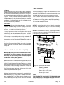
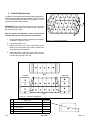
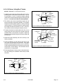
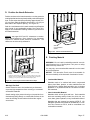
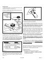
See Figure 2.4 on page 12, for location and operation.
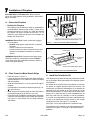
Caution! Outside air control handle may be warm. Adjust
before lighting fire.
4/12
433-1390K
Page 11
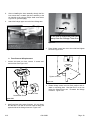
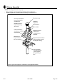
Automatic Combustion
Control Handle
Auxiliary
Convection
Air Lever
ACC Override
Lever
Outside Air Control
Handle
(Keep open during use. )
Figure 2.4 General Operating Parts
I. Fan Operation
Fan operating instructions with Fan Override Switch in manual postition
G. Clear Space Near the Fireplace
Combustible materials must not be stored on the hearth extension. Room furnishings such as drapes, curtains, chairs
or other combustibles must be at least 4 ft (1219mm) from
the open front of the fireplace.
1. Initial (cold) Startup: Leave fan off until your fireplace is hot and a good coal bed is established, approximately 30 minutes after fuel is lit.
H. Glass Doors
This fireplace has been tested and listed for use with doors
as specified in Section 12, page 70. Warning! Risk of Fire and Smoke! Fireplaces
equipped with doors should be operated only with
doors fully open or doors fully closed. If doors are left
partly open, gas and flame may be drawn out of the
fireplace opening.
Warning! Risk of Fire! Do NOT install and or use
any component not approved by Hearth & Home Technologies Inc.
4/12
NOTICE: The fan is equipped with a snap disc that will
turn the fan on and off depending on the temperature of the
fireplace. If the fan is not coming on at the desired time,
flip the override switch to manual and operate the fan as
described below.
2. High Burn Setting: The fan may be left on throughout
the burn.
3. Medium or Medium High Burn Setting: The fan
should be left off until a good burn is established, then
turned on medium or high rate.
4. Low Burn Setting: The fan tends to cool off the fireplace. Leave fan off until the burn is well established;
then, if you wish, turn the fan on at a low rate.
The override switch and the fan speed control are hard wired
at time of installation and installed in a standard wall mount
with junction box on the wall.
433-1390K
Page 12
1. What To Do if Your Stove is Over-Firing
J. Fire Safety
To provide reasonable fire safety, the following should be
given serious consideration:
1. Install at least one smoke detector on each floor of
your home to ensure your safety. They should be
located away from the heating appliance and close
to the sleeping areas. Follow the smoke detector
manufacturer’s placement and installation instructions,
and be sure to maintain regularly. 2.
A conveniently located Class A fire extinguisher to
contend with small fires resulting from burning embers.
3.
A practiced evacuation plan, consisting of at least two
escape routes.
4.
A plan to deal with a chimney fire as follows:
Immediately close the door and air controls to reduce air supply to the fire.
•
If you suspect a chimney fire, call the fire department
and evacuate your house.
•
Contact your local chimney professional and have your
stove and stove pipe inspected for any damage.
•
Do not use your stove until the chimney professional informs you it is safe to do so.
Hearth & Home Technologies WILL NOT warranty stoves
that exhibit evidence of over-firing. Evidence of over-firing
includes, but is not limited to:
• Warped air tube
• Deteriorated refractory brick retainers
In the event of a chimney fire:
• Deteriorated baffle and other interior components
a.
Notify fire department
b.
Prepare occupants for immediate evacuation.
c.
Close all openings into the stove.
d.
While awaiting fire department, watch for ignition
of adjacent combustibles from overheated stove
pipe, hot embers or sparks from the chimney.
K. Over-Firing Your Appliance
WARNING Fire Risk! Do not over-fire
Over-firing may ignite creosote or will damage the stove
and chimney.
To prevent over-firing your stove. DO NOT:
• Use flammable liquids
• Overload with wood
• Burn trash or large amounts of scrap lumber
• Permit too much air to the fire.
•
Symptoms of over-firing may include one or more of
the following:
•
Chimney connector or appliance glowing
•
Roaring, rumbling noises
•
Loud cracking or banging sounds
•
Metal warping
•
Chimney fire
4/12
•
L. Chimney Fire
In the event of a chimney fire:
• Have the chimney and adjacent structure inspected by
qualified professionals. Hearth & Home Technologies
recommends that NFI or CSIA certified professionals, or
technicians under the direction of certified professionals,
conduct a minimum of an NFPA 211 Level 2 inspection
of the chimney.
• Replace components of the chimney and fireplace as
specified by the professionals.
• Ensure all joints are properly engaged and the chimney
is properly secured.
A chimney fire can permanently damage your chimney system. Failure to replace damaged components and make
proper repairs creates risk of fire.
433-1390K
Page 13
M. Starting a Fire
Before lighting your first fire in the fireplace, make certain that
the baffle and the ceramic blanket are correctly positioned. It should be resting against the rear support. Also refer to
care and cleaning of plated surfaces on Section 4 before
lighting your first fire.
NOTICE: Fireplace should be run full open for a minimum
of 30 minutes a day during heating season to keep air passages clean.
NOTICE- The first three or four fires should be of moderate
size to allow the oils and binders to be burned from the
fireplace and the refractory and paint to cure. You may
notice an industrial odor the first few fires. This is considered
normal.
NOTICE: Remove all labels from glass
before lighting the first fire in your
APPLIANCE.
There are many ways to build a fire. The basic principle
is to light easily-ignitable tinder or paper, which ignites the
fast burning kindling, which in turn ignites the slow-burning
firewood. Here is one method that works well:
1. Open Outside Air by turning the knob counter clockwise.
2. Fully open the Combustion Air Control Handle by
moving it completely to the right.
3. Place serveral wads of crushed paper on the firebox
floor. Heating the flue with slightly crumpled newspaper before adding kindling keeps smoke to a minimum.
4. Lay small dry sticks of kindling on top of the paper.
5. Make sure that no matches or other combustibles are
in the immediate area of the fireplace. Be sure the
room is adequately ventilated and the flue unobstructed.
6. Light the paper in the fireplace. NEVER light or rekindle fireplace with kerosene, gasoline, or charcoal lighter fluid; the results can be fatal.
7. Once the kindling is burning quickly, add several fulllength logs 3 in. (76mm) or 4 in. (102mm) in diameter.
Be careful not to smother the fire. Stack the pieces of
wood carefully; near enough to keep each other hot,
but far enough away from each other to allow adequate air flow between them.
8. Adjust the Combustion Air Control; the more you close
down the control, (sliding left) the lower and slower
the fire will burn. The more you open the Air Control,
(sliding right) the more heat will be produced and the
faster the wood will burn.
As long as there are hot coals, repeating steps 7 and 8 will
maintain a continuous fire throughout the season.
.
4/12
Warning! Risk of Fire! Keep combustible materials,
gasoline and other flammable vapors and liquids clear of
the fireplace.
Do NOT:
• store flammable materials close to the fireplace
• use gasoline, lantern fuel, kerosene, charcoal lighter
fluid or similar liquids to start or “freshen up” a fire in this
fireplace.
Keep all flammable liquids well away from the fireplace while
it is in use. Combustible materials may ignite.
Warning! For use with solid wood fuel only.
Other fuels may overfire and generate poisonous gases
(i.e. carbon monoxide).
N. Burning Process
Fire requires 3 things to burn: fuel, air and heat. If heat is
robbed from the fireplace during the drying stage, the new
load of wood has reduced the chances for a good clean burn. For this reason, it is always best to burn dry, seasoned firewood. We do not advise burning unseasoned wood, however
if it happens, you must open the Combustion Air Control and
burn the fireplace at a high burn setting for a longer time to
start it burning.
Kindling or 1st stage:
The first stage of burning is called the kindling stage. In this
stage, the wood is heated to a temperature high enough to
evaporate the moisture which is present in all wood. The
wood will reach the boiling point of water (212°F) and will not
get any hotter until the water is evaporated. This process takes
heat from coals and tends to cool the fireplace.
433-1390K
Page 14
2nd stage:
The next stage of burning, the secondary stage, is the period
when the wood gives off flammable gases which burn above
the fuel with bright flames. During this stage of burning it is
very important that the flames be maintained and not allowed
to go out. This will ensure the cleanest possible fire. If you
are adjusting your fireplace for a low burn rate, you should
close down the air to the point where you can still maintain
some flame. If the flames tend to go out, the fireplace is set
too low for your burning conditions. Final stage:
The final stage of burning is the charcoal stage. This occurs
when the flammable gases have been mostly burned and
only charcoal remains. This is a naturally clean portion of
the burn. The coals burn with hot blue flames.
It is very important to reload your fireplace while enough
lively hot coals remain in order to provide the amount of heat
needed to dry and rekindle the next load of wood. It is best
to open the air control for a short while before reloading. This livens up the coalbed. Open door slowly so that ash or
smoke does not exit fireplace through opening. You should
also break up any large chunks and distribute the coals so
that the new wood is laid evenly on hot coals.
P. ACC Override
The lever located to the right of the Combustion Air Control
is the ACC OVERRIDE and may be used to override the
setting of the Combustion Air Control. If the ACC has been
activated and burn rate needs to be slowed, move the
lever to the LEFT and position Combustion Air Control at
the preferred setting. To close the air supply for an over
fire situatution or to slow the burn rate down immediately,
slide the lever to the LEFT and also slide the Combustion
Air Control all the way to the left.
NOTICE: If reloading a bright, hot coal bed for longer (low)
burn time, setting the ACC may not be required. Burn Dry,
well seasoned wood.
NOTICE: To establish your settings, always begin with the
air control all the way to the left to STOP and then move it
to the right for your desired setting.
Fireplace operation does require air. Do not take air from
other fuel burning appliances which can result in improper
venting (smoking) or air dilution. Always provide adequate
makeup air.
Left - Close
Right - Open
O. Automatic Combustion Control (ACC)
IMPORTANT! As you move the Combustion Air Control
to the RIGHT, you will feel resistance about three-fourths
of the way. You must move past that resistance approximately 3/4 in. (19mm) to fully engage the Automatic
Combustion Control (ACC) sytstem.
With the Automatic Combustion Control system that is on this
fireplace, you can set the fireplace to high (slide the Combustion Air Control all the way to the right), start the fire, and then
move the Combustion Air Control to the desired burn level. The fireplace will automatically go to that level once the fire
is fully established. This allows for less interaction with the
fire by the homeowner and more efficient use of fuel while
maintaining the desired heat output.
After the fireplace has been in operation for a period of time,
and is warmed up; you may prefer to not activate the ACC
when reloading fuel. if you do not slide the Combustion Air
Control all the way to the right, the ACC will not be activated.
4/12
Low
Setting
Meet
Resistance
Move past
3/4" to High
High
Setting
Figure 2.5 Operating the ACC Controls
*Slide Air Control
Slide LEFT to Stop
Stop to 1/8 in. -1/2 in. open
Stop to 1/2 in. - 1-1/2 in. open
All the way to RIGHT
Notice:
THE DECORATIVE FASCIA MUST BE REMOVABLE ON
YOUR FIREPLACE IN ORDER TO SERVICE THE AUTOMATIC COMBUSTION CONTROL SYSTEM.
433-1390K
Page 15
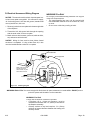
Q. Auxiliary Convection Air System
The Auxiliary Convection Lever allows you to choose
where the convection air is coming from if the auxiliary
duct has been installed and the lever lock was removed.
Moving the lever to the RIGHT will bring air into the bottom of the fireplace from the duct and put it into the room
as heated air.
Moving the lever all the way to the LEFT will cause the
room air to be pulled into the bottom grille of the fireplace,
and re-circulate into the room as heated air.
NOTICE: If you live in an area with very cold winter
months, you will want to use room air as opposed
to bringing in extremely cold air from outside of the
home. This will eliminate creating a draft of cold outside air infiltrating your home. Definitely keep the lever to the LEFT when not using the fireplace.
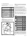
Burn Rate
Low
Medium
Medium High
High
BTU / Hr
Below 10,000
10,000 - 15,000
15,000 - 30,000
Maximum Heat
*Combustion Air Control
Slide LEFT to Stop
Stop to 1/8 in. -1/2 in. open
Stop to 1/2 in. - 1-1/2 in. open
All the way to RIGHT
*These are approximate settings, and will vary with type of
wood or chimney draft.
S. Burn Rates
HIGH - Maximum Heat: Fully open (Combustin Air Control
all the way to the right). It is important to do this when reloading the fireplace. Failure to do this could result in excessive
emissions (smoke).
MEDIUM HIGH BURN RATE - 15,000 to 30,000 BTU: After
a wood load has been burning on high for 5 to 15 minutes,
close the Combustion Air Control to 1/2 in. - 1-1/2 in. (13
mm-38 mm) distance open. (Move the handle to left to stop
and then to right for the proper setting).
MEDIUM - 10,000 - 15,000 BTU: After a wood load has been
burning on high for 5 to 15 minutes (longer for very large
pieces or wet wood), Combustion Air Control left to 1/8 in.
-1/2 in. (3 mm-13 mm) distance open. (Move the handle to
left to stop and then to right for the proper setting).
LOW - Below 10,000 BTU: After a wood load has been burning on high for 5 to 15 minutes (longer for very large pieces
or wet wood), gradually slide the Combustion Air Control
left to close down the air, making sure to maintain flames in
the fireplace. It is very important to maintain flames in your
fireplace during the first few hours of a low burn to avoid
excessive air pollution.
Figure 2.6 Auxillary Convection Air Lever location
R. Burning Guidelines
For maximum operating efficiency with the lowest
emissions, follow these operating procedures:
1. Regardless of desired heat output, when loading the
fireplace, burn your fireplace with the Combustion Air
Control wide open (fully to the right) for a minimum
of 5 to 15 minutes.
2. Regulate burn rate (heat output) by using the Combustion Air Control. See Figure 2.5 on page 15.
3. Heat output settings: Follow the burn rate instructions
listed below.
4/12
T. Opacity
This is the measure of how cleanly your fireplace is burning. Opacity is measured in percent; 100% opacity is when an object is totally obscured by the smoke column from a chimney,
and 0% opacity means that no smoke column can be seen. As you become familiar with your fireplace, you should periodically check the opacity. This will allow you to know how
to burn your fireplace as nearly smoke-free as possible (goal
of 0% opacity). 433-1390K
Page 16
3
Troubleshooting
A. Understanding Vent Problems
This fireplace will operate correctly only if adequate ventilation is provided to allow proper draft to the fireplace system.
Hearth & Home Technologies assumes no responsibility for
the improper performance of the fireplace system caused
by inadequate draft due to environmental conditions, down
drafts, tight sealing construction of the structure, or mechanical exhausting devices which will create a negative air pressure within the structure where the fireplace is located.
If smoke spillage occurs from a fireplace opening when the
door is open and the proper chimney height, flue size, and
configuration requirements for the installation have been
met, there is either a leakage in the flue, a blockage in the
flue, or some condition is in effect to draw smoke from the
fireplace into the house. Understanding and differentiating
the conditions which can cause each of these kinds of spillage problems is essential to their solution.
• Flue Leakage
Check for improperly connected flue joints or a damaged
flue joint in the chimney system. Such leakage would
reduce draft (air would be drawn in through the leaks rather
than through the fireplace). The result might be difficult
start-up and smoky fires that might spill if other adverse
draft conditions accompany this problem.
• Flue Blockage
The damper should be open.
B. Draft Problems
This fireplace will operate correctly only if adequate ventilation is provided to allow proper draft to the fireplace system.
Hearth & Home Technologies assumes no responsibility for
the improper performance of the fireplace system caused by
inadequate draft due to environmental conditions, windy conditions, down drafts, tight sealing construction of the structure,
or mechanical exhausting devices which will create a negative
air pressure within the structure where the fireplace is located.
Flue draft is measured as negative pressure in the chimney.
The amount of negative pressure determines how strong
the draft is. The draft is important because it draws the combustion air into the fireplace and pulls the smoke out of the
chimney.
There are three basic criteria essential in establishing
and maintaining flue draft:
•
Availability of combustion air.
•
Heat generated from the fire.
•
Diameter and height of the flue system.
These three factors work together as a system to create
the flue draft. Increasing or decreasing any one of them will
affect the other two and thus change the amount of draft in
the entire system.
or you find it difficult to establish and maintain a moderately
high burn rate, then the flue draft is too low and corrective
measures must be taken.
Be sure you have air available for combustion and that your
firewood is dry and well seasoned. Build your fires properly
and according to the instructions given in operating instructions, “Starting a Fire”. Be sure your flue system is installed
correctly and that it is the proper diameter and height. Check
for the following:
•
All chimney sections are properly installed.
•
The chimney is clean and free of creosote or soot
buildup.
•
Make sure overhanging trees and branches are cut
back within ten feet of the top of the chimney and is
free of debris from animals.
•
Ensure the chimney cap is clean and free of any
buildup of soot or creosote. if cap is equipped with a
spark arrestor screen.
•
Be sure the ceramic blanket (above the baffle) and
the baffle are in their proper positions
•
The wood being used in dry and well seasoned.
If you still suspect you have a low draft problem it may be
necessary to increase the volume of air in your flue system.
Since the diameter of your flue system is matched with the
size of the flue collar and should not be changed, then the
height of the system must be increased. Add chimney sections
a little at a time until the draft improves.
In some cases, regardless of what you do, it can still be difficult to establish the proper flue draft. This is especially evident when using an exterior factory-built chimney or exterior
masonry chimney. Try placing several sheets of crumpled
paper on top of your kindling as close to the flue outlet of
the fireplace as possible. Light this paper first then the paper
under the kindling. The heat generated from the rapidly
burning paper on top of the kindling should help get the draft
established.
Still other factors can affect how well your flue system performs. Neighboring structures, high winds, tall trees, even
hillsides can affect air currents around the chimney. Well
designed chimney caps are available that can help. Your fireplace dealer is the local expert in your area. He can usually
make suggestions or discover problems that can be easily
corrected allowing your fireplace to operate correctly as it
has been designed, providing safe and economical heat for
your home.
If the fire is hard to start and smoke spills out of the fireplace,
433-1390K
4/12
Page 17
nd
ti
ina
m
r
e
t
y
e
chimn
?
on
Bird's nest
or leaves in
termination
cap?
ds
ar
ou
Overhanging
tree?
in
gw
n
o
r
t
S
Structural
changes in
chimney area?
Another appliance in
home also exhausting
air (furnace, fan,
Unsealed
dryer, etc.)?
can lights?
Overhead fan
operating?
Creosote buildup
in flue?
Air register from
furnace near
fireplace?
Doors opening
and closing?
Window closed
for start-up?
Combustion
air control
Outside air
closed?
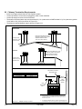
Figure 3.1 Factory-built Fireplaces: Troubleshooting
4/12
433-1390K
Page 18
C.Diagnostics and Problem Solving
1. If I can’t get a good fire going, what am I doing wrong?
Diagnostic Question
Possible Causes of Condition
Solutions
Are the air controls open?
• No draft
• No combustion air
Open air controls
Is there enough paper?
Insufficient heat to ignite kindling
Use more paper
Is there enough kindling?
Is the kindling dry?
Insufficient heat to ignite fuel
Use drier kindling
Is there enough or too much wood?
Is it too large?
Is it dry enough?
•
•
•
•
Use small split wood that is well seasoned (split, covered on top minimum 6
months, preferably a year)
Insufficient heat to establish draft
Insufficient air passage
Insufficient surface area
Ignition temperature high due to
moisture
Are there adequate air spaces
between fuel pieces?
Insufficient combustion air and exposed
surface area
Arrange kindling and wood for air movement
Is the chimney pre-warmed?
Exposed, cold chimney downdrafting
Use lighted rolled newspaper at flue
opening to start upward air movement
Is there smoke in the house?
Does the kindling wood not ignite?
• Obstruction in chimney
• Downdraft from chimney temperature or from negative house pressure
Condition, amount, arrangement of
kindling and fuel
• Have chimney checked if it worked
previously
• Pre-warm chimney
• Shut off exhaust devices
• Open window slightly
Use more, drier, well-spaced kindling
and fuel.
Does the kindling ignite, but the fuel
doesn’t?
• Amount of kindling
• Condition of fuel
• Use more kindling
• Use smaller, dry wood
Does the fuel ignite, but not burn well?
• Draft problem
• Condition of fuel
• Use well-seasoned wood and sufficient amount
• Turn exhaust fans off
• Open window slightly
2. I smell smoke in the house after we have had a fire. What is the cause/what can I do?
Diagnostic Question
Is the chimney clean?
Possible Causes of Condition
No: Creosote odor
Solutions
Have chimney cleaned
3. I smell smoke in the house during operation. What is causing it?
Diagnostic Question
Do fires start and burn well?
Possible Causes of Condition
No:
• Chimney obstruction
• Not enough kindling and/or fuel to
establish draft
• Inadequate combustion air
• Air controls not open
Yes:
Competition with exhaust devices
4/12
433-1390K
Solutions
No:
• Check & clean chimney if needed
• Use adequate kindling & fuel
• Open air controls
• Open window
• Check for need for balanced air
make-up (Outside Air)
• Check door rope for seal.
Yes:
• Do not use exhaust fans during
startup
• Check for need for balanced air
make-up (Outside Air)
Page 19
4. I don’t get enough/any heat. What can I do about it?
Diagnostic Question
Possible Causes of Condition
Solutions
How much wood is used for fire?
Insufficient fuel
Make larger fires
How well seasoned is the wood?
Condition of fuel
Burn seasoned wood: (split, covered
on top minimum 6 months, preferably a
year) (about 20% moisture)
Did you install a fan?
Snap disc may be faulty
Replace snap disc
How much heat output do you expect?
• Unrealistic expectations
• Heat output too low for square footage
Replace appliance with one with greater
heat output
How are air controls set?
Operational problems
Follow manufacturer’s instructions
5. The wood burns too fast. What can I do?
Diagnostic Question
4/12
Possible Causes of Condition
Solutions
What is the condition of the wood?
Extremely dry wood
Mix in less seasoned wood after fire
established
How are air controls set?
Operational problems
Follow manufacturer’s instructions
Fireplace won’t shut down.
ACC Timer is not working properly
Call qualified Quadra-Fire dealer
433-1390K
Page 20
4
Maintenance and Servicing the Fireplace
A. General Maintenance
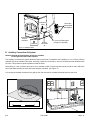
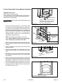
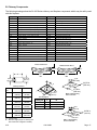
1. Creosote (Chimney) Cleaning
Frequency: As necessary; at least annually before lighting
stove, or once every 2 months during heating season.
Formation and Need For Removal: When wood is burned
slowly, it produces tar and other organic vapors which combine
with expelled moisture to form creosote. The creosote vapors
condense in the relatively cool chimney flue of a newly-started or a
slow-burning fire. As a result, creosote residue accumulates on the
flue lining. When ignited, this creosote creates an extremely hot fire
which may damage the chimney or even destroy the house. The
chimney connector and chimney should be inspected once every
2 months during the heating season to determine if a creosote or
soot buildup has occurred. If creosote or soot has accumulated,
it should be removed to reduce the risk of a chimney fire.
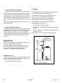
•
•
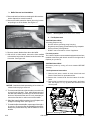
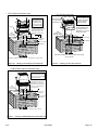
Remove screws,
lift top cover.
Top Cover
Cap
Chimney
By: Homeowner / Chimney Sweep
Task: See the following instructions.
Remove all ash from the firebox and extinguish all hot embers
before disposal. Allow the appliance to cool completely. Disconnect flue pipe or remove baffle and ceramic blanket from
appliance before cleaning chimney. Otherwise residue can pile
up on top of the baffle and ceramic blanket and the appliance
will not work properly. (See Baffle Removal on page 25.) Close
the door tightly. The creosote or soot should be removed with a
brush specifically designed for the type of chimney in use. Clean
out fallen ashes from the firebox. A chimney sweep can perform
this service. It is also recommended that before each heating season the
entire system be professionally inspected, cleaned and repaired
if necessary.
Warning! Risk of Fire! Ignited creosote is extremely HOT.
Prevent creosote buildup.
WARNING! Asphyxiation Risk! Fire Risk!
Annual inspection by qualified technician recommended.
Check:
• Condition of doors, surrounds and fronts
• Condition of glass and glass assembly
• Obstructions of combustion and ventilation air
• Obstructions of termination cap
Clean:
•Glass
• Air passageways, grilles
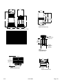
TR344/TR342
Round
Termination Cap
Remove 4 screws
and lift top pan off.
Cap
Slip
Section
ST375
Square
Termination Cap
1. Remove the 4 screws.
2. Remove the screen.
3. Remove the baffle.
Cap
Chase
TS345/TS345P
Square
Termination Caps
Remove 2 screws from
the front and back and
lift the top off.
Inspection: Inspect the system at the appliance connection and at
the chimney top. Cooler surfaces tend to build creosote deposits
quicker, so it is important to check the chimney from the top as well
as from the bottom.
In the event of a chimney fire, Hearth & Home Technologies Inc.
recommends
TCT375
Terra Cotta
Termination Cap
Figure 4.1 Chimney & Termination Cap Cleaning
• replacement of the chimney, and
• inspection of the adjacent structure to the provisions of NFPA
Level III inspection criteria.
4/12
433-1390K
Page 21
2. Disposal of Ashes
4. Care and Cleaning of Plated Surfaces
Frequency: As necessary
By: Homeowner
Task: See the following instructions.
Clean-plated surfaces with vinegar or a glass cleaner before
lighting your first fire to prevent permanent staining.
•
CAUTION!
• Do not use polishes with abrasives. It will scratch plated
surfaces.
•
Ashes should be placed in a metal container with a
tight fitting lid. The closed container of ashes should
be placed on a non-combustible floor or on the ground,
well away from all combustible materials, pending final
disposal.
If the ashes are disposed of by burial in soil or
otherwise locally dispersed, they should be retained in
the closed container until all cinders have thoroughly
cooled.
WARNING! Fire Risk! Do not use chimney cleaners or flame
colorants in your appliance. Will corrode pipe.
CAUTION!
Clean all the fingerprints and oils from the surface before
firing the appliance for the first time.
• Use a glass cleaner or vinegar and towel to remove the
oils.
• Oils can cause permanent markings on plating, if not
removed.
• After plating is cured, oils will not affect the finish.
Warning! Risk of Fire! Ashes could contain hot embers.
WARNING! Fire Risk! Disposal of Ashes
• Ashes should be placed in metal container with tight
fitting lid.
• Do not place metal container on combustible surface.
• Ashes should be retained in closed container until all
cinders have thoroughly cooled.
3. Glass Cleaning
Frequency: As necessary
By: Homeowner
Task: See the following instructions.
Clean glass with a non-abrasive glass cleaner. Abrasive
cleaners may scratch and cause glass to crack. If the
deposits on the glass are not very heavy, normal glass
cleaners work well. Heavier deposits may be removed
by using a damp cloth dipped in wood ashes or by using
a commercially available oven cleaner. After using an
oven cleaner, it is advisable to remove any residue with
a glass cleaner or soap and water. Oven cleaner left on
during the next firing can permanently stain the glass and
damage the finish on plated metal surfaces.
A portion of the combustion air entering the firebox is
deflected down over the inside of the door glass. This air
flow “washes” the glass, helping to keep smoke from adhering to its surface. When operated at a low burn rate, less
air will be flowing over the glass and the smoky, relatively
cool condition of a low fire will cause the glass to become
coated. Operating the appliance with the Burn Rate Air
Control and Start-Up Air Control all the way open for 15-20
minutes should remove the built up coating. 4/12
5. Door and Door Gasket
Periodically check the door gasket for proper seal. As the
gasket compresses or “seats” during use, it may become
necessary to adjust or tighten the door latch.
To Adjust or Tighten Door Latch
Remove spacing washers shown in Figure 4.2. At least
one spacing washer and the black washer must be left
in place.
OR
Replace the gasket material. Wear or damage to the
gasket material can cause air leakage into the firebox
resulting in overfiring and loss of efficiency.
A replacement gasket is available from your dealer. Hinge Pins &
Washers
Left Door
Right Door
Latch Cam
Spacing Washers
Fiber Handle
Locknut
Locking
Pin
Square
Key
Left Handle
Assembly is
stationary
Black Washer
DO NOT REMOVE
Door Handle Shaft
Figure 4.2 Door Handle Assembly
433-1390K
Page 22
6. Maintenance Task List
Inspect
Screens
Maintenance Tasks
1. Assess condition of screen and replace as necessary.
2. Verify maintenance of proper clearance to combustible household objects.
Glass Doors
1. Inspect glass panels for cracks. Replace if this condition is present.
2. Confirm there is no damage to glass or glass frame. Replace as necessary.
3. Inspect door rope. Confirm glass does not move around in glass frame
4. Clean glass using a non-abrasive cleaner.
Door Rope
(Dollar Bill Test)
1. Open door, place half of dollar bill inside, and close door.
2. Attempt to pull the bill out.
3. If the bill gives good resistance or is not removable, the rope is adjusted correctly.
If the bill comes out too easily, the door rope needs adjustment to create an even thickness all around door.
Air Intakes
1. Remove any foreign objects.
2. Verify unobstructed air circulation.
Firebox
1. Inspect condition of brick. Replace if crumbly, deteriorated, or if cracks exceed 1/4 in. (6 mm).
Chimney
1. Inspect for blockage or obstruction such as bird nests, leaves, etc.
2. Confirm that termination cap remains clear and unobstructed by plants, etc.
3. Verify that termination cap clearance to subsequent construction (building additions) has been maintained.
4. Inspect for corrosion or separation.
5. Verify weather stripping, sealing and flashing remain intact.
6. Inspect for creosote and remove as needed.
B. Replacement Maintenance
1. Glass Replacement
9.
1.
Ensure that the fire is out and the appliance is cool to
the touch.
2.
Protect a table or counter top with padding or towels.
3.
Remove door with broken glass from the appliance by
lifting door up and off of the hinges.
4.
Lay door face down on a table or counter making sure
handle and handle attachment knob hang over the edge
of the table top so door lays flat, on a soft surface.
5. Remove screws from the top and bottom glass frames
(5 on each door) using a #2 Phillips Head screwdriver. Set frames aside and retain screws.
HINT: Soak screws in penetrating oil for easy removal.
6.
Remove the glass and discard.
7.
Position the new glass with edges evenly overlapping
the opening in the front door.
8.
Replace the glass frames. Be careful not to cross thread
the screws.
4/12
Start screws to secure glass frames to door, keeping
them loose for adjusting the glass. Then continue to
tighten each screw alternately, a few turns at a time,
until the glass panel is tightened snugly. DO NOT
OVERTIGHTEN SCREWS.
10. Replace the door on the appliance.
11. After the first burn, recheck the tightness of the screws.
NOTICE: Remove all labels from glass before
lighting the first fire in your APPLIANCE.
433-1390K
Page 23
2. Firebrick Replacement
The firebox of your fireplace is lined with high quality firebrick,
which has exceptional insulating properties. There is no need
to use a grate; simply build a fire on the firebox floor. Do not
operate the fireplace without bricks.
5
5
5
5
5
5
5
5
5
5
IMPORTANT: The bricks are very similar in size. Be certain
you have the proper brick in the correct location. Measure
the brick size for accuracy.
3
5
5
5
5
1
1
5
5
3
2
4
2
2
2
After the coals are completely cooled, remove all old
firebrick and ash from unit and vacuum out firebox.
2
4
1. Remove new brick set from box and lay out to diagram
as shown in Figures 4.3 & 4.4.
Figure 4.3 Fire Brick Configurations
2. Lay bottom bricks in unit.
3. Install rear bricks on the top of the bottom bricks. Slide top of bricks under clip on back of firebox wall
and push bottom of brick back.
4. Install side bricks. Slide top of brick under clips on
side of firebox and push the bottom of the brick until
it is flush with the side of the unit.
5
5
5
5
5
Back
Left Side
Right Side
5
5
5
5
1
5
5
5
5
5
4
2
2
2
2
2
1
5
5
4
3
3
Floor
Figure 4.4 Fire Brick Configurations
#
4/12
Brick Size
Qty. In Set
1
9” x 3-1/4” x 1-1/4” Angled (see drawing)
2
2
6-1/4” x 4-1/2” x 1-1/4”
5
3
9” x 2” x 1-1/4”
2
4
6-1/4” x 3-1/2” x 1-1/4”
2
5
9” x 4.5” x 1-1/4”
16
433-1390K
9.0"
3-1/4"
1
1-1/4"
Page 24
3. Baffle Removal and Installation
1.Remove all ash from firebox, and extinguish all hot embers
before disposal into a metal container.
2.Remove the baffle protection channel by turning it down
and pulling it out of the firebox. See Figure 4.5
Figure 4.7 Removing Baffle (shown without ceramic blanket)
4. Fan Replacement
CAUTION! Shock Risk!
Circulating Fireplace Only
• Do NOT remove grounding prong from plug.
• Plug directly into properly grounded three-prong receptacle.
• Route cord away from appliance.
• Do NOT route cord under or in front of appliance.
Figure 4.5 Removing Baffle Protection Channel
3. Remove ceramic blanket from above the baffle.
4. With a 3/16 in. Allen wrench, remove the front manifold
tube retainer bolt on the air channel under the end of the
front tube. See Figure 4.6.
Fan Cord Location
The 7100FP Fireplace comes standard equipped with two fans,
installed at the factory with electric access on the right side of
fireplace (as you face it).
CAUTION! Shock Risk!
Disconnect power by turning off circuit breaker before
servicing.
Fan Replacement Instructions
1. Remove both doors, outside air knob, black knob and
Fascia. Place Fascia on protected surface.
2. Remove the 6 center bricks from the bottom of the fireplace.
Figure 4.6 Removing Manifold Tube
NOTICE: Soak the bolt with penetrating oil for at least 15
minutes before trying to remove it.
3. Remove the 2 screws from the access panel in the firebox
floor. See Figure 4.8. Pry up panel with screwdriver and
remove panel.
5. To remove manifold tube, slide the tube to one side until
one end is out of its hole. Then, while lifting that end of
the fiber board baffle, pull tube up over the air channel
and out of hole at the other end. It is only necessary to
remove the first tube in order to remove the baffle.
6. Slide fiber board baffle forward to front of fireplace and
straight out through door. See Figure 4.7
7. To install the fiber board baffle, repeat steps 2 through 4
in reverse. Be sure the fiber board baffle and ceramic
blanket are pushed back fully and the blanket is down
and flat.
Screws
Screwdriver Slot
Figure 4.8 Accessing Fan Motor
4/12
433-1390K
Page 25
Removing the fan
5. Timer Assembly Replacement
1. Unplug the wire harness.
2. Lift fan from locating pins and remove. Repeat for
second fan if necessary. See Figure 4.9.
3. Connect new fan wires to wire harness.
4. Before installing the fan, make sure the grommets are
tightly in place. Insert the right fan and place over the 2
locating pins. Repeat for other fan. Figure 4.10
5. Re-install bottom panel or firebox access panel in
reverse order as described above.
CAUTION Shock Risk!
Disconnect power by turning off circuit breaker BEFORE
servicing.
1. Remove both doors, outside air knobs, Fascia, and
brick.
2. Remove 2 Phillips head screws and pry open access
door in the bottom of the fireplace with a flat head screwdriver. Figure 4.11
6 Replace the brick that was removed.
7. Re-install the Fascia and both knobs.
8. Re-install both doors and hinge pins.
Remove 2 screws and
pry open access door.
9. Reconnect the power.
Figure 4.11
Unplug wire
harness before
removing fan
Open Access Door
3. Remove 2 screws and take off access cover. Figure 4.12
Remove nut
and lift out fan
Figure 4.9 Fan Motor
Figure 4.12
Access Cover
NOTICE: The timer assembly included in this kit comes
with the air chamber cover attached. Figure 4.13.
4. You will need to disconnect air chamber cover from timer
assembly before installing in the fireplace. Set screws
aside for later use. Figure 4.14 on page 27.
Air Chamber Cover is
attached to Timer Assembly
Figure 4.10 Installing Fans
4/12
Figure 4.13 Timer Assembly with Air Chamber Cover
(Linkage arm is not included in the kit)
433-1390K
Page 26
Remove 2
screws
Figure 4.17
Figure 4.14
5. Remove 2 screws from timer linkage upper arm. Be
careful NOT TO DROP arm in bottom of fireplace. Figure
4.15.
Move arm left
Arm must be in this position
when re-installing
Be careful not to
drop Linkage Arm
down into fireplace
Rotate assembly up and
out through access door
Figure 4.18
7.
Figure 4.15
6. Remove 2 screws from timer mounting plate. Place
your hand into the access door in the floor of the fireplace. Let the timer assembly and plate drop down and
rotate it up through the access door. You will be looking
at the back side of the assembly. Figures 4.17 & 4.18.
Remove old air chamber cover. Place the cover under
the bottom of the firebox. Using a 7/16 wrench attach
the (2) 1/4-20 bolts as shown in Figure 4.19. Insert the
new timer assembly into the access door with the back
side towards you. Please note the correct position of
the linkage lower arm in Figure 4.18
Firebox Bottom
Timer Plate
Air Chamber Cover
Attach with 1/4-20 bolts
Figure 4.16
4/12
Figure 4.19
433-1390K
Page 27
8.
After re-installing the timer assembly through the firebox access door, re-attach the timer assembly to the
air chamber cover using a Phillips head screw driver. Figure 4.18. (previious page)
9.
Attach the linkage upper arm to the lower linkage arm. D cut side of timer shaft must face
away from the Linkage Timer Arm
Figure 4.22
3. Place linkage control arm over timer shaft and tighten
set screw. Figure 4.23.
Figure 4.20
6. Timer Removal & Replacement
1. Loosen set screw on timer, remove 2 screws and
remove timer. See Figure 4.21
Tighten set screw
Remove
2 screws
Figure 4.23
4. Rotate linkage control arm into final position and reattach to mounting plate. Note that the D cut is now
facing the linkage timer arm. Re-attach the linkage
timer arm. Figure 4.23.
Remove Timer
Loosen Set Screw
Figure 4.21
2. Install new timer using same 2 screws. It is very important that the D cut side of the timer shaft is facing the
opposite side of the linkage timer arm. Figure 4.22
4/12
433-1390K
Page 28
5
5
4
4 3
2
1
3
10
7
8
9
6
Figure 4.24 Exploded View of Entire Assembly for Point of Reference only
Item
4/12
Description
Qty
1
Door Linkage
1
2
Linkage Control Arm
1
3
Bushing
2
4
Washer SAE #10
2
5
Screw 8-32 x 1/2 PH PHL TC
2
6
Linkage Timer Arm
1
7
Attachment Nut & Set Screw
1
8
Screw 6-32 x 1/4 PH PHL TC
2
9
Mounting Bracket
1
10
Timer, Mechanical, 12 hours
1
433-1390K
Page 29
C. Service And Maintenance Log
Date of Service
4/12
Performed By
Description of Service
433-1390K
Page 30
5
Getting Started
A. Typical Fireplace System
Additional lateral
support for chimney
above roof (or enclosed
in chase) if needed
Termination Cap
Storm Collar
Chimney penetrates roof
preferably without affecting
roof rafters
Non-combustible
roof flashing maintains
minimum clearance
around chimney
Offset/Return
(with hanger straps)
Support straps
on rafter supports
chimney (not shown)
Attic insulation shield
(not shown) must be
used here to keep
insulation away
from chimney if
attic is insulated
Ceiling firestop
on floor of attic
Framing headed
off in ceiling joists
Outside
combustion air
Chimney system
Enclosed space above
and around fireplace
Mantel
Combustible
framing/header
on top of V-shaped
standoffs (spacers)
Factory-built fireplace
Decorative facing
and trim
Outside
combustion air
Hearth extension
Protective metal
hearth strip(s)
Figure 5.1 Typical Fireplace System
4/12
433-1390K
Page 31
B. Design and Installation Considerations
D. Negative Pressure
Notice: Check building codes prior to installation.
Warning! Risk of Asphyxiation! Negative pressure
can cause spillage of combustion fumes and soot. Fire
must draft properly for safe operation.
• Installation MUST comply with local, regional, state and
national codes and regulations.
• Consult insurance carrier, local building inspector, fire
officials or authorities having jurisdiction over restrictions,
installation inspection and permits.
Negative pressure results from the imbalance of air available for the fireplace to operate properly. It can be strongest in lower levels of the house.
Before installing, determine the following:
Causes include:
•
•
•
•
•
•
• Exhaust fans (kitchen, bath, etc.)
• Range hoods
• Combustion air requirements for furnaces, water heaters
and other combustion appliances
• Clothes dryers
• Location of return-air vents to furnace or air conditioning
• Imbalances of the HVAC air handling system
• Upper level air leaks such as:
- Recessed lighting
- Attic hatch
- Duct leaks
Where the fireplace is to be installed
The vent system configuration to be used
Gas supply piping
Electrical wiring
Framing and finishing details
Whether optional accessories—devices such as a fan,
wall switch or remote control—are desired
Notice: Junction box should be installed during initial setup
to avoid major reconstruction.
To minimize the effects of negative air pressure:
C. Draft
Draft is the pressure difference needed to vent fireplaces
successfully. When a fireplace is drafting successfully, all
combustion byproducts are exiting the home through the
chimney.
Considerations for successful draft include:
• Preventing negative pressure
• Location of fireplace and chimney
Notice: Hearth & Home Technologies assumes no
responsibility for the improper performance of the fireplace
system caused by:
• Inadequate draft due to environmental conditions
• Downdrafts
• Tight sealing construction of the structure
• Mechanical exhausting devices
• Improper location of the chimney
4/12
• Install the outside air kit with the intake facing prevailing
winds during the heating season
• Ensure adequate outdoor air for all combustion
appliances and exhaust equipment
• Ensure furnace and air conditioning return vents are not
located in the immediate vicinity of the fireplace
• Avoid installing the fireplace near doors, walkways or
small isolated spaces
• Recessed lighting should be a “sealed can” design
• Attic hatches weather stripped or sealed
• Attic mounted duct work and air handler joints and seams
taped or sealed
• Basement installations should be avoided
Notice: Hearth & Home Technologies Inc. recommends
the use of direct vent fireplaces in basements.
433-1390K
Page 32
E. Locating Fireplace & Chimney
Location of the fireplace and chimney will affect performance.
• Install within the warm airspace enclosed by the building
envelope. This helps to produce more draft, especially
during lighting and die-down of the fire.
• Penetrate the highest part of the roof. This minimizes
the effects of wind loading.
• Locate termination cap away from trees, adjacent
structures, uneven roof lines and other obstructions.
• Minimize the use of chimney offsets.
• Consider the fireplace location relative to floor and ceiling
and attic joists.
• Take into consideration the termination requirements in
Section 8 and Section 9.
Notice: Locating the fireplace in a basement or in a
location of considerable air movement can cause intermittent
smoke spillage from fireplace. Do not locate fireplace near
• frequently open doors
• central heat outlets or returns
Recommended
Location
Location
Not
Recommended
Recommended
Location
Marginal
Location
Location NOT
Recommended
Windward
Leeward
Multi-level Roofs
Figure 5.2 Recommended Chimney Locations
4/12
433-1390K
Page 33
F. Tools and Supplies Needed
Before beginning the installation be sure the following
tools and building supplies are available:
Reciprocating saw
Framing material
Pliers
Non-combustible sealant
Hammer
Gloves
Phillips screwdriver
Framing square
Flat blade screwdriver
Electric drill and bits
Plumb line
Safety glasses
Level
Tape measure
1/2-3/4 in. length, #6 or #8 self-drilling screws
Misc. screws and nails
G. Fireplace System Requirements
The Quadra-Fire fireplace system consists of the following:
•
•
•
•
•
•
Fireplace
Firebrick
Chimney termination cap
Chimney system
Hearth extension
Outside air
Required components include:
• Chimney Air Kit (with SL 300 Series Pipe)
• Fascia
Optional components include:
•
•
•
•
Firescreen
Lintel Bar
Heat Zone Kit
Top Vent Kit
H. Inspect Fireplace and Components
Warning! Risk of Fire and/or Explosion! Damaged
parts could impair safe operation. Do NOT install damaged, incomplete or substitute components. Keep fireplace dry.
• Remove fireplace and components from packaging and
inspect for damage.
• Vent system components and doors are shipped in
separate packages.
• Report to your dealer any parts damaged in shipment.
• Read all the instructions before starting the
installation. Follow these instructions carefully
during the installation to ensure maximum safety
and benefit.
4/12
433-1390K
Page 34
6
Framing and Clearances
A. Selecting Fireplace Locations
Several options are available to you when choosing a location for your fireplace. This fireplace may be used as a room
divider, installed along a wall, across a corner or used in an
exterior chase. See Figure 6.1
NOTICE:
• Illustrations and photos reflect typical installations and
are FOR DESIGN PURPOSES ONLY.
• Illustrations/diagrams are not drawn to scale.
• Actual installation/appearance may vary due to individual
design preference.
• Hearth & Home Technologies reserves the right to alter
its products.
Locating the fireplace in a basement, near frequently opened
doors, central heat outlets or returns, or other locations of
considerable air movement can affect the performance and
cause intermittent smoke spillage from the front of the fireplace when no outside air is used. Outside air must be used
for combustion. The 7100FP comes equipped with an outside air inlet to feed combustion air from outside the home,
along with an outside air termination cap. Consideration
should be given to these factors before deciding on a location. See Sections 4 and 5.
NOTICE:
A minimum 1/2 in. air clearance must be maintained at the back and to the sides of the fireplace
assembly.
Chimney sections at any level require a 2 in. minimum air space clearance between the framing
and chimney sections.
NOTICE: In addition to these framing dimensions, also
reference the following sections
• Clearances (Section 6.B)
D
24 in.
(610mm)
E
A
In an exterior chase
or projecting into a
garage
B
Across a corner
A
C
24 in.
(610mm)
F
Along a wall
B
I
As a
H
room
divider
48 in.
(1219mm)
A
B
A
24 in.
(610mm)
G
Figure 6.1 Fireplace Locations
Model # 7100 FP
(Dimensions for finished walls)
4/12
A
B
in. 41-7/8 16
mm 1063 406
C
89-1/2
2273
D
E
F
G
H
I
63-5/16
1608
22-7/16
570
44-3/4
1137
14-1/16
357
55-15/16
1421
50-7/8
1292
433-1390K
Page 35
B. Clearances
Warning! Risk of Fire!
You must comply with all minimum air space clearances to combustibles as specified in Figure 6.2. Do NOT pack required air spaces with insulation or other materials.Framing or finishing material used on the front of, or in front of, the
appliance closer than the minimums listed.must be constucted entirely of non-combustible materials (i.e., steel studs,
concrete boaed, etc.). Failure to comply may cause fire.
Storm Collar
of)
(ro
Roof Flashing
2 in. (51 mm) min.
2 in. min.
(51 mm)
Attic
Insulation
Shield
(attic)
Ceiling Firestop
(ceiling)
2 in. (51 mm) min.
2 in. (51 mm) min.
Ceiling Firestop
Offset/Return with
hanger straps
(ceiling)
2 in. (51 mm) min.
36” from top to
enclosed ceiling
2 in. (51 mm) min.
Must have 2 in. (51 mm)
minimum clearance
to header
0 in. to level
of standoffs
Electrical wires must be 3-1/2: (89mm)
from top
1/2 in. (13 mm) to back
of appliance
0 in.
to floor
1 in. (25mm) to side of appliance
(except at nailing flanges where it is 1/2 in. [13 mm])
Figure 6.2 Clearances to Combustible Materials
4/12
433-1390K
Page 36
1. MINIMUM CLEARANCES TO COMBUSTIBLES
Warning Fire Risk!
Non-combustbile mantels installed at a reduced height may
GET EXTREMELY HOT during use of the fireplace.
DO NOT TOUCH or place heat sensitive combustible items
on the mantel.
WITHIN ENCLOSURE AREA
Appliance to backwall
1/2 in. (13 mm)
Appliance to sidewall
1 in. (25 mm)
Duct boots to framing
0 in. (0 mm)
Top standoffs to header
0 in. (0 mm)
Door opening to sidewall 22-7/8 in. (581 mm)
Faceplate to sidewall
16 in. (406 mm)
Heat zone air grills to ceiling
12 in. (305 mm)
Warning Fire Risk!
Hearth & Home Technologies is not responsible for discoloration, cracking or other material failures of finished
materials due to heat exposure or smoke.
Choose finishing materials carefully.
Mantel minimum height
60 in. (1524 mm)
Maximum mantel depth
12 in. (305 mm)
C. Frame the Fireplace
EXPOSED SURFACES
MANTEL
2. Reduced mantel height / Optional Framing
Construction required:
Non-combustible mantel material minimum height from
base of fireplace to underside of mantel 46 in. (1168mm)
when the following enclosure construction materials are
used:
Non-combustible framing materials must be used above
fireplace to height of 84 in. (2134mm) or to the ceiling
from base of fireplace for all construction materials,
framing members, sheeting, and all finish materials.
3. NON-COMBUSTIBLE MATERIALS
Materials which will not ignite and burn. Such materials are
those consisting entirely of steel, iron, brick, tile, concrete,
slate, glass or plasters, or any combination thereof.
NOTICE: Wiring for fans must be done before framed
enclosure is completed. If using a Heat Zone kit, it also
must be installed before enclosure is complete.
The 7100FP Fireplace will fit a framed opening height of
45-7/8 in. (1165 mm) tall and width of 42 in. (1067 mm). The
finished cavity depth must be no less than 24 in. (610 mm). Framing must extend straight up all the way to the ceiling.
Figure 6.3 shows a typical framing (using 2 x 4 lumber) of
the fireplace, assuming combustible materials are used. All
required clearances to combustibles around the fireplace
must be adhered to. See Figure 6.2, on previous page. Any
framing across the top of the fireplace must be above the
level of the top standoffs. (No recess above standoffs.)
2 in.
Materials that are reported as passing ASTM E 136, Standard Test Method for Behavior of Materials, in a Vertical
Tube Furnace at 750°C, shall be considered non-combustible materials.
(51mm)
4. COMBUSTIBLE MATERIALS
Materials made of or surfaced with wood, compressed paper, plant fibers, plastics, or other materials that can ignite
and burn, whether flame proofed or not, or whether plastered
or un-plastered shall be considered combustible materials.
5. CHIMNEY SECTIONS
12 in.
(305mm)
Position
combustible/
non-combustible
mantel 60 in.
(1524mm)
from base of
the fireplace
45-7/8 in.
Chimney sections at any level require a 2 in. (51 mm) minimum
air space clearance between the framing and chimney section.
(1165mm)
24 in.
(610mm)
42 in.
(1067mm)
Figure 6.3 Framing the Fireplace
4/12
433-1390K
Page 37
D.Electrical Access and Wiring Diagram
WARNING! Fire Risk!
NOTICE: The manual override switch, rheostat speed control and cover plate are supplied. You will need to supply:
14-3 wire with ground; 14-2 wire with ground; standard wall
mount junction box; wire nuts.
1. Remove junction box cover plate on the bottom right side
of the fireplace.
Do not apply combustible finishing materials over any part
of the front of this fireplace.
• The metal fireplace face may only be covered with
noncombustible materials such as ceramic tile, brick,
or stone.
• Do not cover or block any cooling air slots.
2. Thread the 14-3 with ground wire through the opening
with the strain relief on the cover plate.
3. Match colors to wire harness, (red to red, white to white,
etc) and secure with wire nuts.
NOTICE: Wiring for fans must be done before framed
enclosure is completed. If using a Heat Zone kit, it also
must be installed before enclosure is complete.
Standard wall mount with
Junction Box
14-2 w/ground
14-3 w/ground
WIRE NUT
GREEN
Power to the Fireplace
Snap Disc
bypass switch
WHITE
RED
BLACK
WHITE
Match colors to wire
harness (red to red,
white to white, etc) and
secure with a wire nut
Incoming Power
(110V)
BLACK
Figure 6.4
Fan Wiring Diagram
Warning! Risk of Fire! You must comply with all minimum air space clearances to combustibles. Do NOT pack required air spaces with insulation or other materials.
WARNING! Fire Risk!
Comply with all minimum clearances specified.
• A minimum 1/2 in. (13mm) air clearance must be
maintained at the back and 1 in. (25mm) to the sides of
the fireplace assembly.
• Chimney sections at any level require a 2 in. (51mm)
minimum air space clearance between the framing and
chimney section.
4/12
433-1390K
Page 38
7
Installation of Fireplace
Caution! Risk of Cuts/Abrasions. Wear protective
gloves and safety glasses during installation. Sheet metal
edges are sharp.
A. Secure the Fireplace
• Position the Fireplace
This fireplace may be placed on either a combustible or
noncombustible continuous flat surface. Follow the instructions for framing in Section 6.C. Slide the fireplace
into position. Be sure to provide the minimum 1 in. air
clearance at the sides and at back of the fireplace assembly. See Section 6.B.
Warning! Risk of Fire! Prevent contact with sagging,
loose insulation.
• DO NOT install against vapor barriers or exposed
insulation.
• Secure insulation and vapor barriers.
• Provide minimum air space clearances at the sides
and back of the fireplace assembly as outlined in
Section.
Warning! Risk of Fire! Protective metal hearth strips
MUST be installed on combustible surfaces. DO NOT
cover metal strips with combustible materials. Sparks or
embers may ignite flooring.
Pallet
Mounting
Brackets
1 in. (25mm) Overlap
Protective metal strips are placed 2 in.(51mm) under the front of the
fireplace and must extend beyond the front and sides of fireplace
opening by 2 in. (51mm). Nail or screw metal strips in place.
Figure 7.1 Position the Protective Metal Hearth Strips
Top piece must overlap
bottom piece
Raised Platform
2 in.
(51 mm)
1 in. (25 mm) min.
overlap
Floor
2 in.
(51 mm)
Nail or screw metal strips in place.
Figure 7.2 Protect the Front of an Elevated Platform
B. Place Protective Metal Hearth Strips
• Refer to Figures 7.1 and 7.2.
• Locate the two protective metal hearth strips measuring
approximately 26 in. x 4 in. (660 mm x 102 mm) included
with this fireplace.
• Slide each metal strip 2 in. (51 mm) under front edge of
fireplace.
• Overlap strips in the middle of fireplace opening by 1 in.
(25 mm) minimum..
• Metal strips must extend beyond the front and sides of
the fireplace opening by at least 2 in. (51 mm).
• Protect the front of a platform elevated above the hearth
extension with metal strips (not included with fireplace)
per Figure 7.2. See Section 10C for hearth extension
instructions.
C. Install the Outside Air Kit
This fireplace will operate correctly only if adequate ventilation is provided to allow proper draft to the fireplace system.
See Section 5.
An outside air kit must be used for combustion to minimize
the effects of negative pressure within the structure. We
recommend you utilize the shortest duct run to optimize the
performance of the outside air kit. The outside air kit inlet
should be positioned in a manner that will not allow snow,
leaves, etc. to block the inlet. In some installations the air
duct may need to be run vertically. In such an installation,
a 3 ft (914 mm) height difference must be maintained from
the top of the uppermost chimney section to the outside
combustion air inlet. See Figure 7.3 on page 40.
See Figure 7.4 for proper placement of outside air inlet.
The outside air kit is installed on the right hand side of the
fireplace. See Figure 7.5 on page 41 for handle location/
operation.
4/12
433-1390K
Page 39
1. Cut a 6 in. (152 mm) hole in outside wall to accommodate
air piping. See Figure 7.5 on page 41.
2. Use 6 in. (152 mm) metal flex or rigid piping (not
supplied) to directly connect outside air to fireplace
intake. Insulate the pipe to prevent frost condensation.
Attic insulation shield
must be used to keep
insulation away from
chimney.
3. Use the supplied termination cap.
4. Seal between the wall and the pipe with silicone to
prevent moisture penetration and air leaks. 3 ft. (91cm) min. from top of
uppermost chimney
section to air inlet.
Ceiling firestop
on floor of attic.
5. Seal between the termination cap and the house with
silicone to prevent air infiltration.
NOTE: A control knob allows you control of the outside air
inlet. Use of outside air for combustion is required to
conserve heated air within the structure and to provide
make up air to keep the fireplace venting properly.
IMPORTANT! Outside air control considerations
Turn clockwise to “OPEN” positions
Outside air knob must be in the “OPEN” position to operate fireplace properly.
May be closed when not in use to prevent cold air infiltration
Caution! Risk of Fire or Asphyxiation! Do
not draw outside combustion air from wall, floor
or ceiling cavity, or enclosed spaces such as an
attic or garage.
Figure 7.3 Outside Air Inlet Locations
• Do not place outside air hood close to exhaust
vents or chimneys. Fumes or odor could be drawn
into the room through the fireplace.
• Locate outside air inlet to prevent blockage from
leaves, snow/ice, or other debris. Blockages could
cause combustion air starvation.
NO
NO
Attic space
NO
Outlet placed
higher than 3 ft
below the
termination cap
Garage or
combustible
liquids storage
NO
Outlet blocked by
snow, leaves, etc.
Caution! Risk of Cuts/Abrasions. Wear protective gloves
and safety glasses during installation. Sheet metal edges are
sharp.
Use only duct materials
specified by manufacturer
Figure 7.4
4/12
Outside Air Installation
433-1390K
Page 40
Outside Air
intake
Open/Close
Knob for
outside air
CLOSED
Termination
Caps supplied
with fireplace
OPEN
OUTSIDE AIR
Auxiliary
Convection
Air
6 in. (152 mm) Metal rigid or
flex pipe (not provided)
Figure 7.5 Handle location
D. Auxiliary Convection Air System
Both the Outside Air and Auxiliary Air kits are installed
on the right hand side of the fireplace.
The Auxiliary Convection Air system allows the option at the time of installation of the fireplace, to run a 6 inch (152mm)
diameter duct to the outside of the home, and bring outside air over the fans; where it is heated and then distrbuted into
the room. This produces a postive pressure inside the home.
Alternatively, a 6 inch (152mm) duct can be run to another location in the home and used as a cold air return within the
home and distributed into the room where the fireplace is located. See Figure 7.7.
If no ducting is installed, the fans will only pull air from the room and re-circulate heated air back into the room.
Clo
sed
Ope
n
Left = Room Air Right =Auxiliary Air
Figure 7.6 Auxiliary Convection Air Lever
Figure 7.7
4/12
433-1390K
Page 41
E. Auxiliary Convection Air Lever
The Auxiliary Convection Air lever is locked from the factory. If you are going to use this function for air movement
you must remove the lock.
The auxiliary convection lever is located underneath the
front lower panel. See Figure 7.6.
After removing the Fascia, remove the one screw and plate
to allow the handle to be moved in the full motion right to
left. See Figure 7.8.
Discard the plate and screw. Replace Fascia.
Convection Lock Bracket
8-32 Screw
Figure 7.8
4/12
433-1390K
Page 42
8
Chimney Assembly
Notice: Chimney performance may vary.
• Trees, buildings, roof lines and wind conditions affect performance.
• Chimney height may need adjustment if smoking or overdraft occurs.
Termination Cap
Chimney must extend
beyond combustible
roof structure
Additional
support for
tall chimneys
Maintain minimum
height of chimney
above roof
Storm Collar
Install roof flashing
according to minimum
requirements
Maintain minimum
clearances to
combustibles as
specified
Offsets/returns
may not exceed
30° from vertical
Support straps for offsets/
returns must be secured
to adequate framing
Ceiling firestops
are required where
chimney passes
through ceiling or
floor
Figure 8.1 Typical Chimney System - Guidelines for Chimney System Installation
4/12
433-1390K
Page 43
A. Chimney Requirements
NOTICE: You must provide support for the pipe during
construction and check to be sure inadvertent loading has
not dislodged the chimney section from the fireplace or at
any chimney joint.
Vertical distances are measured from the base of the fireplace as shown in Figure 8.2
Minimum overall straight height
13 ft
3.96 m
14.5 ft
4.42 m
Double offset/return minimum height
20 ft
6.1 m
Maximum height
50 ft
15.24 m
Maximum chimney length between an
offset and return
20 ft
6.1 m
Maximum distance between chimney
stabilizers
35 ft
10.67 m
Maximum unsupported chimney
length between the offset and return
6 ft
1.83 m
Maximum unsupported chimney
height above the fireplace
35 ft
10.67 m
Maximum unsupported chimney
above roof
6 ft
1.83 m
Minimum height with single offset/
return
B. Chimney Termination Requirements
To determine the chimney components needed to complete your
particular installation, follow the steps below:
• Determine the total vertical height of the fireplace installation. This
dimension is measured from the base of the fireplace assembly
to the point where the smoke exits the termination cap.
• Subtract the effective height of the fireplace assembly from the
overall height of the fireplace installation (measured from the
base of the fireplace to the bottom of the termination cap, 13 ft.
(4m).
• Refer to Table 8.1 to determine what components must be
selected to complete the fireplace installation.
• Determine the number of ceiling firestops, stabilizers, roof
flashing, etc. required to complete the fireplace installation.
Table 8.1
HEIGHT OF CHIMNEY COMPONENTS
121
FS338
0
0
FS339
0
0
FS340
0
0
SL315
13-3/8
340
SL330
15-1/2
394
RF370
0
0
RF371
0
0
SL306
4-3/4
121
SL312
10-3/4
273
SL318
16-3/4
425
SL324
22-3/4
578
SL336
34-3/4
883
SL348
46-3/4
1187
Offsets/Returns
6 ft (1.83 m) max.
unsupported chimney
above roof
Roof Flashing
6 ft (1.8 m) max.
unsupported
run
Chimney Sections*
20 ft (6.10 m) max.
pipe between an
offset & return
35 ft (10.7 m)
max. straight
unsupported
chimney height
14.5 ft (4.42 m) min. height/single offset-return
20 ft. (6.10 m) min. height/double offset-return
50 ft (15.24 m) max. height
Figure 8.2 Chimney Requirements
4/12
4-3/4
SL3
Ceiling Firestops
Warning! Risk of Fire! You must maintain 2 in. (51
mm) air space clearance to insulation and other combustible materials around the chimney system. Failure to do
so may cause overheating and fire.
44 in.
(1118 mm)
to top of
standoffs
mm
Chimney Stabilizer
NOTICE: A maximum of two pairs of offsets and returns
may be used.
Ceiling firestop
in.
* Dimensions reflect effective height.
Caution! Risk of Fire and/or Asphyxiation! DO NOT
connect this fireplace to a chimney flue servicing another
appliance. Do NOT connect to any air distribution duct or
system. These actions could cause overheating/fire in the
chimney flue, or release of exhaust fumes into the living
areas.
433-1390K
Page 44
C. Using Offsets/ Returns
• Use an offset/return to bypass overhead obstructions.
• An offset and return can be used as a single entity or separated by chimney section(s).
Warning! Risk of Fire! Do not use offset/returns greater than 30°. Chimney draft will be restricted and could cause overheating and fire. Secure offsets vwith screws ( not to exceed 1/2” / 13 mm in length) Secure returns with strapping. Straight
chimney sections may be secured with screws. Keep chimney sections from separating or twisting.
•Measure the shift needed to avoid the overhead obstruction. Refer to dimension A in Figure 8.3.
• Find the appropriate A dimension listed in Table 8.2. The B dimension coinciding with the A dimension measurement in Table
8.2 represents the required vertical clearance needed to complete the offset/return.
• Read across the chart to find the number of chimney sections/model numbers needed between the offset and return.
Example:
A
Your “A” dimension from Figure 8.3 is 14 1/2 in. (368
mm). Using Table 8.2 the dimension closest to, but not
less than 14 1/2 in. (368 mm) is 14 1/2 in. (368 mm) using a 30° offset/return.
B
You determine from the table that you need 34 1/8 in.
(867 mm) (Dimension “B”) between the offset and return.
The chimney component that best fits your application is
one SL324.
1-1/4 in. (32 mm)
OVERLAP
Figure 8.3 Chimney Offset/Return
Table 8.2
15-degree
A
Offset
30-degree
B
Height
A
Offset
SL306 SL312 SL318 SL324 SL336 SL348
B
Height
in.
mm
in.
mm
in.
mm
in.
mm
1-5/8
41
13-3/8
340
-
-
-
-
-
-
3-5/8
92
15-1/2
394
2-7/8
73
17-3/4
451
1
-
-
-
-
-
5-1/2
140
18-5/8
473
4-1/8
102
22-3/8
568
2
-
-
-
-
-
7-1/4
184
21-3/4
552
4-1/2
114
23-5/8
600
-
1
-
-
-
-
8-1/2
216
23-3/4
603
5-3/4
146
28-1/4
718
1
1
-
-
-
-
10-1/4
260
27
686
6
152
29-3/8
746
-
-
1
-
-
-
11-1/2
292
29
737
7-1/4
184
34
864
-
2
-
-
-
-
13-1/4
337
32-1/8
816
7-3/4
197
36-1/8
918
-
-
-
1
-
-
14-1/2
368
34-1/8
867
8-3/4
222
39-3/4
1010
1
-
-
1
-
-
16-1/4
413
37-3/8
949
10-3/8
264
45-5/8
1159
-
-
2
-
-
-
19-1/4
489
42-1/2
1080
10-5/8
270
46-3/4
1187
-
-
-
-
1
-
20-1/2
521
44-5/8
1133
11-7/8
302
51-3/8
1305
1
-
-
-
1
-
22-1/4
565
47-3/4
1213
13-1/2
243
57-1/4
1454
-
-
-
2
-
-
25-1/4
641
52-7/8
1343
13-3/4
349
58-3/8
1483
-
-
-
-
-
1
26-1/2
673
55
1397
15
381
63
1600
1
-
-
-
-
1
28-1/4
718
58-1/8
1476
16-1/2
419
68-3/4
1746
-
1
-
-
-
1
31-1/4
794
63-1/4
1607
18
457
74-5/8
1895
-
-
1
-
-
1
34-1/4
870
68-1/2
1740
19-5/8
498
80-3/8
2042
-
-
-
1
-
1
37-1/4
946
73-3/4
1873
20-5/8
524
84-1/8
2137
1
-
-
1
-
1
39-1/8
994
76-7/8
1953
22-3/4
578
91-7/8
2334
-
-
-
-
1
1
43-1/4
1099
84-1/8
2137
24
610
96-1/2
2451
1
-
-
-
1
1
45-1/8
1146
87-1/4
2216
25-7/8
657
103-1/2
2629
-
-
-
-
-
2
49-1/4
1251
94-1/2
2400
Proper assembly of air-cooled chimney parts result in an overlap at chimney joints of 1-1/4 in. (32 mm). Effective length is built
into this chart.
4/12
433-1390K
Page 45
D. Assemble the Chimney Sections
Warning! Risk of Fire! Do NOT install substitute or damaged chimney components.
Use only those components described in this manual.
Substitute or damaged chimney components could impair
safe operation and cause overheating and fire.
E. Installing CAK4A and Flex Pipe
Attach either a straight chimney section or an offset to the
top of the fireplace (depending on your installation requirement). Chimney sections are locked together by pushing
downward until the top section meets the stop bead on the
lower section.
NOTICE: Chimney Air Kit, Part CAK4A is required when
using the SL-300 Pipe Series. Detailed instructions are supplied with the kit.
If using the Dura-Plus System (must be 8 in. (203 mm) in
diameter), the starter ring that came with the fireplace must
be removed and replaced with the Dura-Plus Base Plate. The
CAK4A is not required with a Dura-Plus System.
The inner flue is placed to the inside of the flue section below it. The outer casing is placed outside the outer casing
of the chimney section below it. See Figure 8.4.
Notice: Chimney sections cannot be disassembled once
locked together. Plan ahead!
• Lock chimney sections and/or offsets/returns together
by pushing downward until the top section meets the
stop bead on the lower section.
• Pull on the top section to make sure it is fully engaged
and will not separate.
• You may use #6 or #8 sheet metal screws no longer
than 1/2 in. (13 mm) to fasten chimney sections
together. Do NOT penetrate inner flue.
1. Install the chimney pipe first.
2. Hand bend the tabs in position before placing on the
fireplace.
3. Place the box on top of the fireplace around the chimney
pipe, push both pieces together and secure with screws
provided.
4. Use the pre-punched holes in the tabs as guides and
drill holes through the fireplace top.
5. Secure the CAK4A in place.
6. Seal around the kit at the flue and at the top of the can
with caulk. See Figure 8.5
Warning! Risk of Fire! You MUST use screws (provided) to fasten offset/returns to chimney sections to keep
the chimney parts from twisting. Failure to do so could
cause fire.
Attach
Flue First
Secure with Screws
Provided
• Fasten offset/returns to chimney sections. Insert the
screws (provided) through the predrilled holes. Do NOT
penetrate inner flue.
• Secure chimney returns with hanger straps provided;
fasten to studs or joists.
• Vertical straight runs of chimney must be supported
every 35 ft (10.7 m).
CAK4A
Push Together
Secure to Top
Figure 8.5 Installing the CAK4A
NOTES:
1. The outside termination cap must be a minimum of 6 ft
(1829 mm) above the ground and kept free of debris. 2. If the CAK4A is installed in a chase, the CAK4A side
termination cap must be at least 3 ft (914 mm) below
the chimney top.
3. Seal around the cap and flex with caulk to stop air from
getting in to the chase (See Figures 9.4-9.8 beginning
on page 53).
4/12
433-1390K
Page 46
WARNING! Fire Risk
The flex hose must never be compressed or deformed!
Restricting the airflow inside the flex pipe may increase
flue pipe temperatures causing a chase fire.
ROOM ABOVE (non-insulated ceiling)
B
A
Wire Ties
4" Flex
Ceilng firestop
attached to bottom
of framing
2 in. (51mm)
clearance
Wire Ties
ATTIC ABOVE (insulated ceiling)
Ceiling firestop
attached to top of
framing
Figure 8.6 Installing Flex Pipe
F. Install Ceiling Firestops
Caution! Risk of Fire! Ceiling firestops must be used
whenever the chimney penetrates a ceiling/floor.
• Install a ceiling firestop whenever chimney penetrates
ceiling/floor.
• Mark and cut an opening in ceiling as shown in Figure 8.7.
• Frame the opening with the same size lumber used in
the ceiling joists.
• Nail the ceiling firestop to the bottom of the ceiling joists
when there is a room above.
• Use an attic insulation shield if the ceiling is insulated.
The ceiling firestop may then be attached above or below
the joists.
• Mark and cut an opening in the ceiling for the ceiling
firestop being used. See Figure 8.7.
• Frame the opening with the same size lumber used in the
ceiling joists.
• Install the firestop spacer.
These firestop spacers are designed to provide the minimum
2 in. (51 mm) air space required around the chimney. In all
situations, the firestop spacers are to be nailed to the ceiling
joists from the bottom or fireplace side, EXCEPT when the
space above is an insulated ceiling or attic space. In this situation, the firestop spacer must be nailed from the top side
to prevent loose insulation from falling into the required 2 in.
(51 mm) air space around the chimney.
4/12
When attic insulation
shield not used
2 in. (51mm)
clearance
Note: Use same dimensional lumber for framing
ceiling firestop and joists.
A
B
Catalog #
in.
mm
in.
mm
FS338
14-1/2
368
14-1/2
368
FS339
14-1/2
368
18-3/8
467
FS340
14-1/2
368
23
584
Figure 8.7 Installing the Ceiling Firestop
NOTICE: The ceiling firestop MUST be nailed to the bottom
of the ceiling joists EXCEPT when the space above is
uninsulated and the attic insulation shield is not being used..
When the attic insulation shield is used the ceiling firestop
may be above or below the joist of an insulated ceiling.
Warning! Risk of Fire! Do NOT seal area between
firestop opening and chimney pipe except where they enter
the attic or leave the warm air envelope of the home (use
600° F sealant).
433-1390K
Page 47
G. Install Attic Insulation Shield
Warning! Risk of Fire! You MUST install an attic insulation shield when there is any possibility of insulation or
other combustible material coming into contact with the
chimney.
• Do NOT pack insulation between the chimney and the
attic insulation shield.
• Failure to keep insulation and other materials away from
chimney pipe could cause fire.
• Do NOT offset chimney inside insulation shield.
Bend inward
90°
Bend remaining tabs
to rest against pipe to
prevent insulation
from falling in.
Insert three
screws
Installation of a ceiling firestop is required
• Refer to Figures 8.8 - 8.10.
• Roll the shield (around the chimney if already installed)
until you have a 3 in. (76 mm) overlap and the three
holes on each side match up (large holes on top).
• Insert three screws into the matching holes to form a
tube.
• Bend three tabs on the bottom of the tube inward to 90°
to maintain chimney air space (refer to Figure 8.8).
• Rest the insulation shield on the ceiling firestop below.
• Bend the three short tabs at the top of the shield inward
to 90° to maintain the 2 in. (51 mm) air space from the
chimney.
• Bend the remaining top tabs to just meet the pipe.
3 in. (76 mm)
overlap
Figure 8.8 Prepare Attic Insulation Shield
Pipe
Attic Insulation Shield
6 Tabs bent
in 90°
If you wish to make a custom shield or barrier, follow
these guidelines:
• Metal is preferred, although any material stiff enough to
hold back the insulation can be used.
Insulation
Warning! Risk of Fire! Use of cardboard or other
materials that can deflect under humidity or other environmental conditions is not recommended.
• The shield or barrier must be tall enough to extend
above the insulation and prevent blown-in insulation
from spilling into the cavity.
• Maintain specified air spaces around chimney.
• Check instructions and local codes for further details.
Tabs bent in to
rest against pipe
Pipe
14-1/2 in. (368 mm)
diameter
Ceiling Firestop
Insulation
10-1/2 in.
(267 mm)
Figure 8.9 Install Attic Insulation Shield (firestop above ceiling)
Tabs bent in to
rest against pipe
Pipe
H. Secure the Chimney
Attic Insulation Shield
14-1/2 in. (368 mm)
diameter
When offsets and returns are joined to straight pipe sections, they must be locked into position with the screws provided* (outer only), using the predrilled holes. To prevent
gravity from pulling the chimney sections apart, the returns
and the chimney stabilizers have hanger straps for securing these parts to joists or rafters. See Figure 8.11 on page
49.
6 Tabs bent
in 90°
Insulation
10-1/2 in.
(267 mm)
Insulation
Pipe
Ceiling Firestop
* Use #6 or #8 sheet metal screw, or larger, no longer than
1/2 in. (13mm).
Figure 8.10 Install Attic Insulation Shield (firestop below ceiling)
4/12
433-1390K
Page 48
WARNING! Risk of Fire!
Secure offsets with screws (not to exceed 1/2in./13mm
in length).
Secure returns with strapping.
Straight chinney sections may be secured with screw
(not to exceed 1/2in./13mm in length) at the joints
Keep chimney sections from separating or twisting.
Straps
I. Double-check the Chimney Assembly
Continue assembling the chimney sections up through the
ceiling firestops as needed. While doing so, be aware of the
height and unsupported chimney length limitations given under Section 8.A. Chimney Requirements.
Check each section by pulling up slightly from the top to ensure proper engagement before installing the succeeding
sections. If they have been connected correctly, they will not
disengage when tested.
Optional
Additional
Support
Ceiling
Firestop
Joint
Band
(Optional)
Figure 8.11 Secure the Chimney
J. Cut out Hole in Roof
•
•
•
•
Refer to Figure 8.11.
Plumb from roof to center of chimney.
Drive a nail up through roof to mark center of pipe.
Measure to either side of nail and mark the 14-1/2 in. x
14-1/2 in. (368 mm x 368 mm) opening required.
• Measure opening on the horizontal; actual length may
be larger depending on roof pitch.
• Cut out and frame opening.
• Refer to Chapter 25 of the Uniform Building Code for
roof framing details.
K. Complete Installation
Warning! Risk of Fire! You MUST maintain 2 in.
(51 mm) air space to insulation and other combustible
materials around the chimney system. Failure to do so
could cause overheating and fire.
The following steps should be skipped if using a
chase.
• Install roof flashing appropriate to roof pitch.
• Install round termination cap and storm collar.
Figure 8.12 Ceiling/Attic Construction
L. Install Flashing
• Assemble chimney so it passes through the framed
opening.
• Slip the flashing over the chimney.
Notice: Roofing shingles must be below the flashing
plate on the lower side of a sloped roof and over the
flashing plate on the sides and top.
4/12
• Nail the flashing to the roof. Keep gaps between the
flashing plate and the roof to a minimum.
• Caulk the flashing plate and roof junction as well as the
vertical seam on the flashing. All nail heads must be
caulked with a roofing sealant.
• Caulk the overlap seam of any exposed pipe sections that are located above the roof line to prevent leaks.
433-1390K
Page 49
M. Chimney Termination Requirements
•
•
•
•
Install a cap approved and listed for this fireplace system.
Locate cap where it will not become plugged by snow or other materials.
Locate cap away from trees or other structures.
The bottom of the termination cap must be at least 3 ft (.91 m) above the roof AND at least 2 ft (.61 m) above any portion
of roof within 10 ft (3.05 m) as shown in Figure 8.13
• The distance required between caps is shown in Figure 8.13.
Slanted Roofs
Chimney must extend 2 ft (.6 m)
above any portion of the roof or
adjacent structures within
10 ft (3 m) of the chimney
Chimney must
extend 3 ft (.9 m)
above the roof
Flat Roofs
Chimney must extend 2 ft (.6 m)
above any portion of the roof or
adjacent structures within
10 ft (3 m) of the chimney
Chimney must
extend 3 ft (.9 m)
above the roof
Multiple Chimney Locations
A
B
6 in. (minimum) up to 20 in.
152 mm/508 mm
18 in. minimum
457 mm
20 in. and over
0 in. minimum
B
A*
Wood
Minimum
(See
illustration
above)
Perpendicular Wall
Gas, Wood or Fuel Oil
Termination Cap
Gas
Termination
Cap **
*
Figure 8.13 Multiple Chimney Locations
4/12
**
If using decorative cap cover(s), this distance may need to be
increased. Refer to the installation instructions supplied with the
decorative cap cover.
In a staggered installation with both gas and wood terminations, the
wood termination cap must be higher than the gas termination cap.
433-1390K
Page 50
N. SL-300 Series Ceiling/Roof Thimble
NOTICE: REQUIRED for manufactured homes.
CHIMNEY
1.Locate the point where the chimney will exit the roof by
plumbing down to the center of the chimney. Lay out,
cut and frame a 14-1/2 in. (368 mm) square opening
(measured on the horizontal) through the ceiling and roof
structure. Consult local codes for framing details.
2.The thimble must extend completely through the roof
structure shielding combustible materials. Five location
holes have been provided to allow for a variety of ceiling/
roof thicknesses. A Thimble Extension is required when
the ceiling/roof thickness exceeds 12-1/2 in. (318 mm). The extension should overlap the thimble one inch.
FLASHING
THIMBLE
EXTENSION
SCREW
NAIL
THIMBLE
Figure 8.15 Installing Part 12966A, Configuration 2
3.To attach the extension to the thimble, drill 1/8 in. (3 mm)
holes through the outer shield of the thimble using the
predrilled holes in the extension as guides. Attach the
extension to the thimble using the screws provided with
the extension.
FLASHING
CHIMNEY
FLASHING
PLATE
THIMBLE
EXTENSION
SCREW
4.Install the thimble assembly and nail it securely to the
framing members.
5.Center the flashing over the chimney and nail it to the
roof using the Stormguard nails provided. Keep gaps
between the flashing plate and the roof to a minimum.
Caulk the flashing plate and roof junction as well as the
vertical seam on the flashing. All nail heads must be
caulked with a roofing sealant.
FLASHING
PLATE
ADJUSTABLE
EXTENSION
HOLES
NAIL
THIMBLE
Figure 8.16 Installing Part 12966A Configuration 3
6.Finish assembling the chimney storm collar and termination cap following the installation instructions provided
with them.
CHIMNEY
FLASHING
FLASHING
PLATE
JOISTS
NAIL
THIMBLE
Figure 8.14 Installing Part: 12966A, Configuration 1
4/12
433-1390K
Page 51
9
Chase Installations
A. Construct the Chase
Round Termination Cap
A chase is a vertical boxlike structure built to enclose the fireplace and/or its vent system. Vertical chimneys that run on the
outside of a building must be installed inside a chase.
Storm Collar
Metal Chase Top
In cold climates, it is recommended that the chase be well
insulated using batt type insulation between the joists.
Ceiling
Firestop
Construction of the chase may vary with the type of building.
These instructions are not substitutes for the requirements of
local building codes. Local building codes MUST be checked.
Chases should be constructed in the manner of all outside walls
of the home to prevent cold air drafting problems. The chase
should not break the outside building envelope in any manner.
All outer walls need to be insulated.
False Ceiling
Building codes require false ceiling and ceiling firestops at each
floor of the chase or every 10 ft (3048 mm) of clear space to
control spread of fire.
Tabs
Attic
Insulation
Shield
Insulation in the
outside walls
of the chase
Ceiling
Firestop
Insulation
Walls, ceiling, base plate and cantilever floor at the first level
of the chase should be insulated. See Figure 9.1. Vapor and
air infiltration barriers should be installed in the chase as per
regional codes for the rest of the home. Additionally, Hearth &
Home Technologies recommends that the inside surfaces be
sheet rocked and taped (or the use of an equivalent method)
for maximum air tightness.
False Ceiling
Insulation
False Ceiling
Chimney
Figure 9.1 Chase Assembly
Holes and other openings should be caulked with high temperature caulk or stuffed with unfaced fiber glass insulation.
Warning! Risk of Fire! You must maintain a minimum
2 in. (51 mm) air space clearance to insulation and other
materials surrounding the chimney system.
Warning! You must install false ceilings and ceiling
firestops at each floor of the chase or every 10 ft (3.05 m)
to control spread of fire.
• Insulation and other materials must be firmly secured to
prevent accidental contact with chimney system.
• The chase must be properly blocked to prevent blown
insulation or other combustibles from entering and
making contact with fireplace or chimney.
• Failure to prevent contact between insulation or other
materials and chimney system may cause overheating
and fire.
Warning! Risk of Fire! Do not seal area between fire
stop opening and chimney pipe except where they enter the
attic or leave the warm air envelope of the home (use 600°
F sealant).
Three examples of chase applications are shown in Figure 9.2
a. The chase is constructed using framing materials much
the same as the walls in your home. A variety of siding
materials may be used including brick, stone, veneer
brick, or standard siding materials.
b. In constructing the chase, several factors must be considered:
1) Maintain a 2 in. (51 mm) air space around the chimney.
2) The chase top must be constructed of non-combustible
material.
3) In cold climates, a firestop spacer should be installed in an
insulated false ceiling at the 8 ft. (2438 mm) level above
the fireplace assembly. This reduces heat loss through
the chase.
4) In cold climates, the walls of the chase should be insulated to the level of the false ceiling as shown in Figure
9.1. This will help reduce heat loss from the home around
the fireplace.
4/12
1. Fireplace and chimney enclosed in an exterior chase.
2. Chimney offset through exterior wall and enclosed in chase.
3. Chase constructed on roof.
All outside walls should be insulated.
1
2
Figure 9.2 Chase Constructions
433-1390K
3
Page 52
B. Install Fireplace & Chimney
• TR344 Round Termination Cap
Termination
Cap
Install as per Sections 7 and 8.
Slip
storm collar
around chimney pipe
before termination
cap pipe is snapped
into the chimney
pipe.
C. Install Chase Top
• You MUST use a chase top in a chase installation. Chase
tops are available from your Quadra-Fire dealer or may
be field constructed.
• Include a turndown and drip edge to prevent water from
seeping into the chase.
• Include a 2 in. (51 mm) soldered, welded or spun collar
around pipe opening to keep water out.
• Provide a 1/8 in. (3 mm) gap around the flue pipe.
• Slope the chase top downward away from the opening.
Caulk gaps between
storm collar & pipe,
and storm collar
& chase top.
Collar
2 in. (51 mm)
Minimum Height
Warning! Risk of Fire! Do not caulk the pipe to the
chase top collar.
Do NOT
block air holes
6 in. (153 mm)
Minimum top of
chase to top of
chimney pipe
Storm
Collar
Chimney
Pipe
Chase Top
• Caulk all seams to prevent leaks.
Slope Downward
(1/4 in. per foot
minimum)
2 in. (51 mm) Collar
on Chase Top
Chase
Turn-down
Termination cap pipe and chimney section must be snapped
together to maintain an overlap of 1-1/2 in. (38 mm).
Drip Edge
Figure 9.4 Installing a TR344 Round Termination Cap
Chase
• TR342 Round Telescoping Termination Cap
Assemble
storm collar
around extended
termination cap
pipe
once cap is
installed.
.018 (26 ga) min.
Galvanized
Chase Top
Figure 9.3 Chase Top Construction
Caulk gaps between
storm collar & pipe,
and storm collar
& chase top.
D. Install Termination Cap
Install the chimney sections up through the chase enclosure.
• Caulk the overlap seam of any exposed pipe sections Termination
Cap
Storm
Collar
Collar
2 in. (51 mm)
Minimum Height
that are located above the roof line to prevent leaks.
Do NOT
block air
holes
3 clip brackets.
Slip over chase collar
and attach with screws
provided.
14 1/2 in. (368 mm)
Maximum
Chase Top
• Refer to termination cap instructions.
Warning! Risk of Fire! The minimum overlap of cap
to pipe (as shown in the following illustrations) MUST
be met or chimney may separate from cap. Separation
allows sparks, heat and embers to escape.
Notice: Paint the termination cap with a rust-resistant
paint to protect against the effects of corrosion on those
parts exposed to the weather.
4/12
433-1390K
Chase
Chimney
Pipe
Termination cap pipe and chimney section must overlap 1-1/2 in. (38 mm)
Figure 9.5
Installing a TR342 Round Telescoping Termination Cap
Page 53
• ST375 Square Termination Cap
•
Termination Cap
Collar
2 in. (51 mm)
Minimum Height
Termination Cap
The last section of pipe
must stop between 2 in. (51
mm) above the top of the
chase and 4 3/4 in. (121
mm) below the top of the
chase.
Chase Top
Place waterproof sealer
under each flange of the
termination cap and on
top of each screw to
help prevent leaks.
Remove 2 screws
from front & back
to lift the top off
Place waterproof
caulk or sealer under
each flange of the
termination cap and
on top of each screw
to help prevent leaks.
Flange
TCT375 Terra Cotta Cap
Collar
2 in. (51 mm)
Minimum Height
The last section of pipe
must stop between 2 in.
(51 mm) above top of
chase and 7 in. (178 mm)
below top of chase
Chase Top
2 in. (51 mm)
maximum
2 in. (51 mm)
7 in. (178 mm)
4 3/4 in. (121 mm)
maximum
Chase
Chase
Chimney
Pipe
Chimney
Pipe
Termination cap pipe and chimney section must overlap
1-1/2 in. (38 mm)
Termination cap pipe and chimney section must overlap 1-1/2 in. (38 mm)
Figure 9.6 Installing an ST375 Square Termination Cap
Figure 9.8 Installing a TCT375 Terra Cotta Cap
• TS345/TS345P Square Termination Cap
Place waterproof sealer under
each flange of the termination
cap and on top of each screw
to help prevent leaks.
Termination Cap
The last section of pipe must
stop between 2 in. (51 mm)
above the top of the chase and
4 3/4 in. (121 mm) below the
top of the chase.
Collar
2 in. (51 mm)
Minimum Height
Chase Top
2 in. (51 mm)
maximum
4 3/4 in. (121 mm)
maximum
Chase
Chimney
Pipe
Termination cap pipe and chimney section must overlap 1-1/2 in. (38 mm).
Figure 9.7 Installing a TS345/TS345P Square Termination Cap
4/12
433-1390K
Page 54
10
Finishing
A hearth extension must be installed with all fireplaces to
protect the combustible floor in front of the fireplace from
both radiant heat and sparks.
A. Non-Combustible Materials
• Materials which will not ignite and burn, composed of
any combination of the following:
- Steel
- Iron
- Brick
- Tile
- Concrete
- Slate
- Glass
- Plasters
• Materials reported as passing ASTM E 136, Standard
Test Method for Behavior of Metals, in a Vertical Tube
Furnace at 750° C
B. Combustible Materials
• Materials made of or surfaced with any of the following
materials:
- Compressed paper
- Wood
- Plant fibers - Plastic
• Any material that can ignite and burn; flame proofed or
not, plastered or un-plastered
C. Hearth Extension
WARNING! Risk of fire! High temperatures, sparks,
embers or other burning material falling from the fireplace
may ignite flooring or concealed combustible surfaces.
• Protective metal hearth strips MUST be installed.
• Hearth extensions MUST be installed exactly as
specified.
• You MUST use a hearth extension with this fireplace.
• Refer to Figure 10.1 for minimum dimensions.
• This fireplace has been tested and approved for use with
a hearth extension insulated to a minimum R value of
2.06.
• The hearth extension material MUST be covered with
tile, stone or other non-combustible material.
• Manufactured hearth materials will usually have a
published R value (resistance to heat) or k value
(conductivity of heat). Refer to the formula in Table 10.1
to convert a k value to an R value,
• Refer to Table 10.2 for hearth extension insulation
alternatives.
Table 10.1
R = 1/k x inches of thickness
8 in. (203mm)
from each side of
fuel loading door
A
B
Table 10.2
Hearth Extension Insulation Alternatives, R Value = 2.06
Material
k per inch r per inch
thick
thick
Minimum
thickness
required
Hearth & Home HX4
0.49
2.06
1 in.
USG Micore 300™
0.49
2.06
1 in.
USG Durock™ Cement
Board
1.92
0.52
4 in.
Cement Mortor
5.0
0.20
10 1/2in.
Common Brick
5.0
0.20
10 1/2 in.
Ceramic Tile
12.50
0.08
25 3/4 in.
Armstrong™ Privacy Guard
Plus
0.46
2.18
1 in.
Marble
4/12
14.3-20.0 0.07-0.05
Model # 7100FP
in.
mm
A
B
41
20
1041
508
Figure 10.1 Hearth Extension Dimension
29 1/2 in. 41 1/4 in.
433-1390K
Page 55
Raised Hearth Extension Framing
The hearth framing must be constructed of non-combustible materials (Table 10.2) and placed on an HX4,
or equivalent material (Figure 10.2). When creating the
platform, allow for the thickness of the non-combustible
finishing materials (Figure 10.5).
IMPORTANT! Hear th extension design must be
determined before installation of fireplace.
Floor constructed of wood or
other combustible material
...........
.......................................
.......................................
Fascia
Outer Can
Flange
Protective
Metal Hearth
Strip
Tile or Marble
Min 20 in. (508mm) in front and 8 in. (203mm)
on sides to fuel loading doors
..................................
..................................
Ember Strip (Seal gap with high
temp, noncombustible sealant able
to withstand 300°)
1. Fireplace and Hearth Extension are flush on the
floor:
Non-combustible flooring 20 in. (508mm) in front of and 8 in.
(203mm) to either side of the fuel opening with a minimum
thickness of 1 in. (25mm) and (“k” value = 0.49). See Figure
10.1 on page 55 and Figures 10.3, 10.4, and 10.5.
3/4 in. (19mm)
Plywood
Minimum 4 in. 101.6 mm)
Cement Board or equivalent, (or
two 1/2 in. pieces) and "k" value
= 0.49.
Micore 300
2x4
Figure 10.5 Hearth Extension Flush on Floor but on Raised Platform
2. Fireplace is installed flush on the floor and Hearth
Extension is raised to the bottom of the Fascia:
Raised hearth must be constructed of non-combustible
materials such as cement block or equivalent material. Noncombustible flooring on the raised hearth must be 20 in. (508
mm) in front of and 8 in. (203 mm) to either side of the fuel
opening with a minimum thickness of 1 in. (25 mm) and (“k”
value = 0.49). See Figure 10.6.
Fascia
GAP (SEAL WITH NONCOMBUSTIBLE SEALANT)
UP TO BOTTOM OF FASCIA
Combustible Floor
2x4
2 in. (51 mm)
required
The construction of, and materials used for a hearth extension are shown in Figures 10.1 and 10.3. A hearth extension
of this construction may be covered with any non-combustible
decorative material and may have a maximum thickness as per
Figure 10.2 Seal gaps between the hearth extension and the
front of the fireplace with a bead of non-combustible sealant.
Outer
Can
Flange
6 in. (152mm)
1/2 in. (13mm)
(2) HX4 MICORE FACTORY
BUILT HEARTH EXTENSION
(Each HX4 = 1/2 in. (13mm) thick)
Tile or
Marble
Ember Strip (Seal gap with
High temp, noncombustible Minimum 4 in. (101.6 mm) Cement Board or
equivalent, (or two 1/2 in. pieces)
sealant able to withstand
and "k" value = 0.49. Micore 300
300°)
Figure 10.2 Hearth Extension Construction
NONCOMBUSTIBLE
DECORATIVE MATERIAL
Combustible Floor
Minimum 20 in. (508mm) in front and
8 in. (203mm) on sides to fuel loading doors
...........
Tile, stone or other
non-combustible material
Tile or
Marble
Figure 10.4 Fireplace and Hearth Extension Flush on the Floor.
High temperature
(300°F min.) continuous,
non-combustible sealant
Fireplace
2 thickness of HX4
Hearth Ext
or equivalent insulation
(see Table below)
Fascia
Outer Can
Flange
Min 20 in. (508mm) in front and 8 in.
(203mm) on sides to fuel loading doors
.. .. .. .. .. .. .. .. .. .. .. .. .. .. .. .. .. .. .. .. .. .. .. .. .. .. .. .. .. .. .. .. .. .. ..
HEARTH METAL STRIPS
Ember Strip
(Seal gap with
noncombustible
sealant)
Non-combustible
framing materials
Combustible Floor
3/4 in.
(19mm)
Plywood
2x4
Figure 10.3 Side View of Factory Built Hearth Extension
Tile or Marble
Minimum 4 in. (101.6 mm)
Cement Board or equivalent,
(or two 1/2 in. pieces) and
2x4
"k" value = 0.49. Micore 300
Figure 10.6 Raised Hearth Extension to Bottom of Fascia
4/12
433-1390K
Page 56
D. Position the Hearth Extension
Position and secure the hearth extension over the protective
metal strips that have been placed partially under the fireplace
front. These strips should be protruding approximately 2 in.
(51 mm) from under the fireplace front and 2 in. (51 mm) on
both sides of the fireplace opening. See Figure 10.7.
Seal the crack between the hearth extension and fireplace
with a bead of non-combustible sealant. See Figure 10.8. Apply a non-combustible finishing material of your choice to
the hearth extension.
NOTICE: see pages 36-37 and 55, “clearances to combus-
tibles, hearth extensions / floor protection” for clearances
required for different hearth extension installations. The
clearances must be strictly adhered to.
Seal with
non-combustible
sealant
Figure 10.8 Position the Hearth Extension
E. Finishing Material
WARNING! Do not install combustible materials over the
metal fireplace face of the fireplace! This poses a safety
hazard and may start a fire.
Pallet
Mounting
Brackets
You may only use noncombustible material over the metal
face of the fireplace. NOTICE: The decorative Fascia must be removable for
future serviceability of the Automatic Combustion Control.
1 in. (25mm) Overlap
Protective metal strips are placed 2 in.(51mm) under the front of the
fireplace and must extend beyond the front and sides of fireplace
opening by 2 in. (51mm). Nail or screw metal strips in place.
• Combustible Material
Figure 10.7 Positioning the Protective Metal Hearth Strips
Warning! Fire Risk!
Hearth extensions are to be installed only as illustrated
to prevent high tempertures from occurring on concealed
combustible materials.
Materials made of or surfaced with wood, compressed
paper, plant fibers, plastics, or other materials that can
ignite and burn, whether flame proofed or not, or whether
plastered or un-plastered shall be considered combustible materials.
• Non-Combustible Material
Hearth sealing strips prevent burning or hot particles from
inadvertently falling directly on combustible surfaces in the
event the building should settle and disturb the original
construction.
4/12
433-1390K
Materials which will not ignite and burn. Such materials
are those consisting entirely of steel, iron, brick, tile, concrete, slate, glass or plasters, or any combination thereof.
Materials that are reported as passing ASTM E 136,
Standard Test Method for Behavior of Materials, in a Vertical Tube Furnace at 750°C, shall be considered noncombustible materials.
Page 57
• Non-Combustible Sealant Material
F. Mantel
A combustible mantel may be positioned no lower than 60
in. (1524mm) from the base of the fireplace.
Sealants which will not ignite and burn: Super Calstick
After completing the framing and applying the facing material (drywall) over the framing, a bead of non-combustible
sealant must be used to close off any gaps at the top and
sides between the fireplace and facing to prevent cold air
leaks. Large gaps can be bridged with fiberglass rope gasket.
Only non-combustible materials may be used to cover the
metal fireplace front.
The combustible mantel may have a maximum depth
of 12 in. (305mm). Combustible trim pieces that
project no more than 3/4 in. (19mm) from the face
of the fireplace can be placed no closer than 6 in.
(152mm) from the top or side of the decorative front. Combustible trim must not cover:
• the metal surfaces of the fireplace
• Cardboard OR Metal Template
A cardboard template of the front is printed on the outside of
the shipping box. It measures 1/8 in. (3 mm) bigger all the
way around than the actual front. Cut out the template
along the outside of the line for use in your installation.
A metal template is also available for more durable continued
use remaining accurate over time. See page 76 for catalog
number.
• where the non-combustible board is placed over the metal
surfaces
• the space between the metal face of the fireplace and
framing members
Refer to page 37 for reduced mantel height allowances
Warning Fire Risk!
Maintain clearances
Use only non-combustible material below standoffs, material such as cement board is acceptable.
Framing or finishing material used on the front of, or in
front of, the appliance closer than the minimums listed,
must be constructed entirely of non-combustible
materials (i.e., steel studs, concrete board, etc.).
Mantel
Clearances are
from bottom of
appliance to lower
edge of mantel or
trim
Trim
60 in.
(1524mm) 48 in.
(1219mm)
WARNING! Fire Risk
Hearth & Home Technologies is not responsible for discoloration, cracking or other material failures of finishing materials due to heat exposure or smoke.
• Choose finishing materials carefully.
Figure 10.9 Mantel Specifications
4/12
433-1390K
Page 58
G. Non-Combustible Facing Material Installation
WARNING! Risk of Fire!
Follow these instructions exactly.
Facing materials must be installed properly to prevent fire.
No materials may be substituted without authorization by
Hearth & Home Technologies
1in. (25mm) OVERLAP
TOOLS NEEDED: Powered drill with #2 Phillips head bit; caulking gun.
Figure 10.10
Metal strips 2 in. (51mm) under edge of
Fireplace and Hearth Extension and 2 in.
(51mm) on both side of fireplace opening.
Nail or screw metal strips in place.
1. Secure the fireplace to the floor or wall framing studs
at a minimum of two attachment points to prevent further movement of the fireplace. The same holes and L
brackets that attached the fireplace to the pallet may
be used to secure the fireplace to the sub flooring by
using a minimum of two 1/4 in. x 2 in. lag bolts or
equivalent. Refer to Figure 10.10 and install the two
metal hearth strips at this time.
Top
Board
Side
Board
NOTE: All boards are pre-drilled for your convenience. Boards MUST be attached in the following
order: bottom, top, and then the two sides.
2. Attach the bottom board to the bottom of the outer fire-
place can with enclosed screws, ensuring the board is
centered.
Bottom
Board
Apply bead of
Super Calstick to
edge here
Side
Board
Figure 10.11
3. Center and attach the top board to the outer can and
framing members.
4. Using the Super Calstick, run a light bead (1/8 in. mini-
mum) on the butt edges of the top board. See Figure
10.11 5. Ensuring the top of the side pieces and the top board
align, attach the side pieces to the outer can and framing members.
6. Use a wet or dry towel or a soft brush to remove any
Figure 10.12
Seal with
non-combustible
sealant
dust or dirt from facing material. Apply a non-combustible adhesive to attach tile, stone or other non-combustible finishing materials per manufacturer’s instructions.
7. The non-combustible Super Calstick may be used for
sealing between the fireplace and the hearth extension. Refer to Figure 10.12.
Figure10.13 Complete installation
4/12
433-1390K
Page 59
11
Accessories
A. Heat Zone Kit (Optional)
DUCT RUN REQUIREMENTS
The Heat-Zone accessory kit conveys warm air from the fireplace through air duct(s) to remote locations in the same room
or other rooms of the building. You may install 1 or 2 Heat-Zone
kits on the fireplace. Follow the instructions that is supplied with
the kit. Installation of this kit MUST be performed by a qualified service technician. If any parts are missing or damaged,
contact your local dealer before starting installation. DO NOT
install a damaged kit. MAXIMUM Duct Run = 40-ft. (12m)
MINIMUM Duct Run = 36 in. (914mm)
DUCTING MATERIAL
6 in. (152mm) B-Vent Only
DO NOT DUCT into existing furnace plenum
MINIMUM CLEARANCE TO COMBUSTIBLES
1 in. (25mm) from the B-Vent
1/2 in. (13mm) from top & bottom of outlet box
0 in. (0mm) from the sides of outlet box
12 in. (305mm) from wall register to ceiling
(See Figure 11.1).
This kit is tested and safe when installed in accordance with
this installation manual. It is your responsibility to read all
instructions before starting installation and to follow these
instructions carefully during installations.
Installation of this kit MUST by performed by a qualified service technician.
The Heat-Zone® Wood kit is carefully engineered and must
be installed only as specified. If you modify it or any of its
components you will void the warranty and you may possibly
cause a fire hazard. Installation must be done according to
applicable local, state, provincial and/or national codes.
Plan the location of the fireplace and warm air duct run(s).
Caution! ALL wiring should be done by a qualified electrician and shall be in compliance with local codes and with
the National Electric Code NFPA/NEC No. 70-current.
CSC22.1 Canadian Electric Code.
Possible Air Duct Runs / Locations
12 in. (305mm) minimum clearance
from register to ceiling
Wall Register
Ceiling Register
Floor Register
Ceiling Register
Two Duct Kits
Figure 11.1
4/12
Minimum Clearances to Combustibles
433-1390K
Page 60
INSTALLATION
1. Remove the knockout or cover plate from the top of the
fireplace and discard it. See Figure 11.2.
2. Cut a 3 in. (76mm) hole in the insulation board as per the
dimensions shown in Figure 11.2.
3-13/16 in.
(97mm)
3-1/8 in. (79mm)
CL
Adapter
Figure 11.4
Mounting
Plate
6. Slide the starter pipe into the fireplace, matching the holes
in the plate to the holes in the fireplace.
Starter Pipe
7. Place the Adapter on the Mounting Plate lining up holes.
Using the 4 sheet metal screws included in the kit, secure
the Adapter and Mounting Plate into fireplace. After securing to the fireplace, tape down the Adapter edges to the top
of the fireplace with aluminum tape to prevent leakage.
Knockout
m)
(76m d
3 in.
ar
Cut a lation bo
u
in ins
hole
Figure 11.2
3. Determine the necessary length of starter pipe from the
following table and cut as required. See Figure 11.3
4. The starter pipe is shipped flat. After cutting to the required
length, manually roll the pipe together and snap lock into
place. NOTE: It is important the pipe length be adhered
to or it will affect the performance of your fireplace.
Run Length 20 - 40 ft (6-12m)
Cut Pipe
2 in. (51mm)*
*A minimum of 2 in. (51mm) pipe must be used to
cover the raw insulation to prevent it tfrom blowing out through the Return Air Grille.
10 - 20 ft (3 - 6m)
8 in. (203mm)
3 - 10 ft (1 - 3m)
No cut needed**
**Use full 16 in. (406mm) as supplied
NOTICE: The fan and electrical connections must be
accessible for servicing per local code requirements.
NOTICE: If the fan housing is installed in a 2 x 4 wall,
the front of the housing will protrude approximately 1/4
in. (6mm) from the finished wall. See Figure 11.5 on
page 63.
9. Attach enough 6 in. (152mm) B-Vent as required for
your installation to the fan housing. A maximum of (4) 90°
elbows is recommended. Securely twist lock the B-Vent
to the Adapter.
Also screw the B-Vent to the outlet box on the fan housing. See Figure 11.6 on page 63. Support duct at intervals of no
greater than 4 ft (1 m) as required by local code.
Warning Fire Risk!
Comply with all minimum clearances specified.
Figure 11.3
5. On the Mounting Plate, hand bend the tabs downward. Slide the tabs over the outside of the starter pipe. Secure
with 4 sheet metal screws included in fasteners package.
Figure 11.4.
4/12
8. Determine the location for the air register and fan housing
assembly. Cut a 7-5/8 in. x 13-5/8 in. (143 x 346mm) hole
between framing members (wall studs or floor joists). The
brackets can be rotated 180° and mounted to the back side
of the 2 x 4 if necessary. See Figure 11.6 on page 63.
• A minimum 1 in. (13mm) air clearance must be
maintained at the back and 1 in. (25mm) to the sides
of the fireplace assembly.
433-1390K
Page 61
NOTICE: Secure the duct so that clearance to the fireplace
outer wrap is maintained. Tape all seams with aluminum
tape 1-1/4 in. (32mm) minimum width or as specified by local
codes.)
2 x 4 Wall
Fan Housing
10. Seal all the way around the inside of the Return Air Grille
to prevent hot air being drawn back into the venting system
using gasketing supplied with the kit. Leave 1/4 in. (6mm)
clearance from all 4 outer edges. Trim excess gasketing. See Figure 11.7
Seal grille using gasketing supplied with
the kit
2 x 4 wall
1/2 in. (13mm)
clearance to
combustibles
must be
maintained.
Leave 1/4" (6mm) clearance from
all 4 outer edges
Figure 11.7
Sheet Rock
Figure 11.5
Secure B-Vent to Fan Housing
with sheet metal screws
11. Install the variable speed wall rheostat (with setting on
“OFF”) in a convenient location. This switch will control the
Heat-Zone fan operation.
12. Remove the Junction Box. Wire 110 VAC service TO the
wall rheostat and FROM the wall rheostat to the fan Junction
Box. Use wire nuts to secure the 110 VAC service wires to
the hot (black) and neutral (white) fan wires and screw the
110 VAC ground wire to the Junction Box. See Figure 11.8
13. Secure the Return Air Grille to the fan housing making
sure it is flush. The grille must be installed with the louvers
pointing down.
NOTICE: DO NOT USE ADJUSTABLE REGISTERS.
Bracket
Can rotate
180o
Junction Box
Securely Twist
Lock B-Vent to
Adapter
White
Black
Return Air Grille
Install with Louvers
pointed down
14. Complete the fireplace installations as per the instructions found in your Owner’s Manual.
Wire Nuts
Wire Clamp
Junction Box Removed
Figure 11.6
4/12
Figure 11.8
433-1390K
Page 62
B. Firescreen
A firescreen must be used to control sparks if the homeowner choses to operate the fireplace with the doors open;
and it must remain in place whenever the fireplace will be
operating in this manner. Glass doors or firescreens must
not be used to hold burning material inside the fireplace.
Only those glass doors specifically tested and listed for use
with the specific fireplace model should be used.
Use both hands to stabilize the screen. Ensure that the
screen is fully attached. Be careful not to stack wood close
to the front or too high that logs could roll out the front. Start
with a small fire and adjust your heat to desired setting. If
smoke spillage occurs, put on gloves and then remove the
screen and close the doors. Refer to Troubleshooting Draft
Problems on page 17.
WARNING! Fire Risk!
• Close firescreen when burning fireplace.
• Do not use firescreen or glass doors to hold burning
material in fireplace.
Firescreen controls sparks.
Glass may break or burning material may roll out.
• Always wear gloves when installing or removing the
screen as the screen may become extremely hot while
in use.
C. Fascia (Fronts)
Fronts are required to complete the installation. The 7100
fireplace allows a choice of fronts, therefore they are
shipped separately from the unit due to customer preference and selection. Instructions for attachment of the
fronts are included with them. Contact your local dealer
with any questions on offerings or installation
4/12
433-1390K
Page 63
12
Reference Materials
A.Fireplace Dimensions
FRONT VIEW
SIDE VIEW
A
N
F
B
E
M
D
J
L
C
I
Blower Electric Access
(right side of fireplace)
K
TOP VIEW
C
L
G
H
7100FP
A
B
in
3-1/2
32-1/2
mm
89
826
H
I
in.
13-3/16
mm
335
C
D
E
F
G
38
40
42-5/16
45-13/16
23-7/16
965
1016
1075
1148
595
J
K
L
M
N
10-13/16
4-5/16
13-3/4
9-7/16
6
1
259
109
349
240
152
25
Figure 12.1
4/12
433-1390K
Page 64
Fireplace Diagram
11
12
10
18
17
13
9
16
15
20
8
14
19
27
25
26
7
23
21
24
5
4
2
1
22
Item
#
1
2
3
4
5
6
7
8
9
Description
Fascia, Valley Forge
Door Handle, Left
Handle, Fiber
Door Handle, Right
Glass Assembly
Glass Frame, Bottom
Glass Frame, Top
Brick, Set
Manifold Tube(s)
6
Item
#
10
11
12
13
14
15
16
17
18
Description
Unit Collar
Starter Plate Assembly
Blanket, Ceramic
Baffle, Fiberboard
Clamp, Cable 3/8-1/2 in.
Junction Box Cover Plate
Fan
Bracket, Fan
Fan Access Panel
3
Item
#
Description
19
20
21
22
23
24
25
26
27
Snap Disc
Hearth Strip
Outside Air Kit
Fascia, Mission Hill
Timer Assembly
Timer Control Arm
Timer Arm, Upper
Wiring Harness
Secondary Control Arm
Figure 12.2 - Fireplace Diagram
4/12
433-1390K
Page 65
Components Diagrams and Schematics
Item
7
42
2
33 4 34 35
3
36
Door Handle, Left
433-2030
3
Handle, Fiber
7000-403
4
Door Handle, Right
433-0770
Glass Assembly
433-5750
Glass Frame, Bottom
433-1620
7
Glass Frame, Top
433-1610
30
Screw, 6-32 x 1/4
available only in assy.
31
Door, Cast, Left
available only in assy.
32
Gasket, 1/8 x 1/2
available only in assy.
33
Set Pin, 1/8 x 5/8
7000-163
34
Washer, 3/8
222-0010
40
35
Latch Cam Key
430-1151
39
36
Washer, 5/8 x 0.406
available only in assy.
37
Cam Latch
32084
41
32
2
5
5
31
SKU
6
6
30
Description
37 38
Glass Size: 12-3/50” w x 15” h
38
Nut, Lock 3/8-16
available only in assy.
39
Door, Cast, Right
available only in assy.
40
Washer, 1/4
28758
41
Hinge Pin
GD: 229-1240
NL: 229-1250
42
Screw, 8-32 x 1/2
220-0490
Figure 12.3 - Door, Glass & Door Handle Assembly
48
Item
49
47
50
46
51
52
44
45
Description
SKU
43
Grille Bar Assembly, Bottom
433-5120
44
Grill Bar Assembly, Side
433-5210
45
Combustion Air Label
available only in assy.
46
Fascia Stiffener
available only in assy.
47
Bracket, Fascia Support
available only in assy.
48
Bracket, Mission Hill Support
available only in assy.
49
Fascia Assembly
available only in assy.
50
Screw, 1/4-20 x 1/2
available only in assy.
51
Grille Bar Assembly, Top
433-5130
52
Screw, 1/4-20 x 1-1/4
available only in assy.
43
Figure 12.4 - Valley Forge Fascia Assembly
4/12
433-1390K
Page 66
B.Chimney Components
The following drawings show the SL-300 Series chimney and fireplace components which may be safely used
with this fireplace.
Catalog No.
Decsription
Catalog No.
Description
CAK4A
Chimney Air Kit
CB876
Chimney Bracket
ID4
Insulated Duct / Outside Air
RF370
Roof Flashing - Flat to 6/45 Pitch
UD4
Uninsulated Duct / Outside Air
RF371
Roof Flashing - 6/12 to 12/12 Pitch
SL306
Chimney Section - 6 in. (152 mm) long TR344
Round Termination Cap
SL312
Chimney Section - 12 in.(305 mm) long
TR342
Round Telescoping Termination Cap
SL318
Chimney Section - 18 in. (457 mm) long
ST375
Square Termination Cap
SL324
Chimney Section - 24 in. (610 mm) long
TS345
Square Termination Cap
SL336
Chimney Section - 36 in. (914 mm) long
DTO134
Short Octagon Decorative Cap
SL348
Chimney Section - 48 in. (1219 mm) long
DTO146
Tall Octagon Decorative Cap
SL3
Chimney Stablizer
DTS134
Short Square Decorative Cap
SL315
Chimney Offset / Return - 15°
DTS146
Tall Square Decorative Cap
SL330
Chimney Offset / Return - 30°
CT35M
Chase Top (Sold in pack of 10)
FS338
Firestop - Straight
12966A
Manufactured Home Thimble
FS339
Firestop - 15°
MH841
Manufactured Home Thimble Extension. 20 in. ( 508 MM)
FS340
Firestop - 30°
HX4
MICORE Hearth Extension, 20 in. (508 mm) wide
AS8
Straight Attic Insulation Shield
JB877
Chimney Joint Band
CT-3A
Adapter - May be used with the following copper caps
9201
Simpson Dura-Plus Base Plate
CT-Series
DT-Series
INSULATED DUCT
UNINSULATED DUCT
4 in.
4 in.
(102 mm)
42 in.
42 in.
A
(10669 mm)
(10669 mm)
UD4
ID4
10-1/2 in.
8 in.
12 in.
(305 mm)
(267 mm)
(203 mm)
(102 mm)
24-5/8 in.
(625 mm)
A
Chimney Sections
Catalog
No.
SL306
A
B
6 in.
(152 mm)
4-3/4 in.
(121 mm)
SL312
12 in.
(305 mm)
10-3/4 in.
(273 mm)
SL318
18 in.
(457 mm)
16-3/4 in.
(425 mm)
SL324
24 in.
(610 mm)
22-3/4 in.
(578 mm)
SL336
36 in.
(914 mm)
34-3/4 in.
(883 mm)
SL348
48 in.
(1219 mm)
46-3/4 in.
(1187 mm)
B
14-1/2 in.
(368 mm)
RF370 - Roof Flashing
Flat to 6/12 Pitch
Firestop Spacer
Catalog No.
A
B
FS338
0°
14-1/2” (368 mm)
FS339
15°
18-3/8” (467 mm)
FS340
30°
16-3/4” (425 mm)
12in.
(305 mm)
24-5/8 in.
(625 mm)
31 in.
(787 mm)
A = Actual Length
B = Effective length (length of chimney part
after it has been snapped to another)
4/12
27-3/8 in.
(695 mm)
RF371 - Roof Flashing
6/12 to 12/12 Pitch
433-1390K
Page 67
10-1/2 in.
(267 mm)
20-3/4 in.
(527 mm)
Inside
Diameter
8 in.
2 in.
10-1/2 in.
(51 mm)
(267 mm)
(203 mm)
CB876
Chimney Bracket
Outside
Diameter
10-1/2 in.
JB877
Joint Band
(267mm)
SL3 - Chimney Stabilizer
72 in.
Inside
Diameter
8 in.
36 in.
(1829 mm)
(203 mm)
Outside
Diameter
10-1/2 in.
(914 mm)
10-7/8 in.
MH841
Manufactured Home
Thimble Extension 20 in.
(276 mm)
(508 mm)
2 in.
(267 mm)
(51 mm)
CT35M
Chase Top
SL315-SL330 - Offset/Return
24-5/8 in.
29 in.
(737 mm)
(625 mm)
12966A
Manufactured Home
Thimble
16-5/8 in.
(422 mm)
16-5/8 in.
(422 mm)
TR-TVK - Round
Termination Top Vent Kit
12 in.
12 in.
(305 mm)
24 in.
(610 mm)
(305 mm)
10-1/2 in.
(305 mm)
5-1/4 in.
(133 mm)
4 in.
(102 mm)
AS8
Straight Attic
Insulation Shield
4/12
CAK4A
Chimney Air Kit
433-1390K
Page 68
B
B
13-1/4 in.
(337 mm)
16-1/4 in.
(413 mm)
22 in.
(559 mm)
A
23-1/8 in.
(587 mm)
A
18 in.
(457 mm)
C
C
DTS134/DTS146
DTO134
DTO146
DTS134
DTS146
TS345/TS345P
Square Termination Cap
DTO134/DTO146 Decorative Caps
in
mm
A
34
864
B
20
508
C
24
610
in
mm
46
1168
22.7
576
26
660
in
mm
A
34
864
B
21.18
538
C
24
610
in
mm
46
1168
21.18
538
26
660
TR342
TERMINATION CAP
CHASE TOP
14-1/2 in.
(368 mm)
MAX.
DISTANCE
TOP OF
UPPERMOST
CHIMNEY
SECTION
TR342
Round Telescoping
Termination Cap
23 in.
(584 mm)
19 in.
(483 mm)
15-3/4 in.
(400 mm)
15-5/8 in.
(397 mm)
TR344
Round Termination Cap
4/12
ST375
Square Termination Cap
433-1390K
Page 69
R
7100 FP
C. Service Parts
Beginning Manufacturing Date: Mar 2005
Ending Manufacturing Date: Active
7100FP-BK-B, 7100FP-GD-B, and 7100FP-NL-B (Aug 2006 - Active)
7100FP-BK, 7100FP-GD and 7100FP-NL (Mar 2005 -- July 2006)
1
18
17
2
16
3
4
5
15
14
6
13
7
8
9
10
11
12
MISSION HILL FASCIA
VALLEY FORGE FASCIA
Part number list on following page.
4/12
433-1390K
Page 70
R
7100 FP
Service Parts
Beginning Manufacturing Date: Mar 2005
Ending Manufacturing Date: Active
IMPORTANT: THIS IS DATED INFORMATION. When requesting service or replacement
Stocked
at Depot
parts for your appliance please provide model number and serial number. All parts listed
in this manual may be ordered from an authorized dealer.
ITEM
1
DESCRIPTION
COMMENTS
PART NUMBER
Starter Plate Assembly
SL1
Starter Section Assembly 8”
22069B
2
Header Shield
480-1130
3
Ceramic Fiber Blanket, 1 In.
832-3401
Y
4
Baffle Board
SRV433-0910
Y
5
Manifold Tube Set
TUBES-433
Y
832-0661
Y
SRV433-5080
Y
Manifold Clip/Screws
6
Pkg of 4
Timer Assembly - Complete Timer Assembly
Y
Component Pack
433-5700
Gasket, Timer
433-1290
Timer Replacement
SRV480-1940
Y
#7 Brick Set
7.5
9.0"
3-1/4"
7.1
7.5
7.5
1-1/4"
7.3
7
7.5
7.5
7.5
7.5
7.5
7.5
7.5
7.5
7.5
7.5
7.5
7.5
7.1
7.1
7.4
7.5
7.2
7.2
7.2
7.2
7.2
7.4
Brick Assembly - Complete Set
Pkg of 27
BRICK-433
7.1
Brick, 9” x 3.25” x 1.25” Angled (see diagram)
Qty. 2 Req.
433-6080
7.2
Brick, 6.25” x 4.5” x 1.25”
Qty. 5 Req.
433-6090
7.3
Brick, 9” x 2” x 1.25”
Qty. 2 Req.
433-6110
7.4
Brick, 6.25” x 3.5” x 1.25”
Qty. 2 Req.
433-6120
7.5
Brick, 9” x 4.5” x 1.25”
Qty. 16 Req.
832-2370
Pkg of 6
832-3030
Pre 0071580458
DF-7100MH
Brick Uncut, Clay
8
9
Fascia, Mission Hill
7.3
Post 0071580458 DF-7100MH-B
Screw, BH SH 1/4-20 x 1.25 BLK
Pkg of 24
225-0630/24
Y
Screw, 1/4-20 x .5 Button Head
Pkg of 20
32328/20
Y
Nut, Tinnerman Cage 1/4-20
Pkg of 4
812-2980
Y
Component Pack
433-5520
Knob, Chad, Mission Hill Front
2005-193
Pre 0071580458
Fascia, Valley Forge
DF-7100VF
Post 0071580458 DF-7100VF-B
Component Pack
433-5520
Additional service part numbers appear on following page.
4/12
433-1390K
Page 71
R
7100 FP
Service Parts
Beginning Manufacturing Date: Mar 2005
Ending Manufacturing Date: Active
IMPORTANT: THIS IS DATED INFORMATION. When requesting service or replacement
Stocked
at Depot
parts for your appliance please provide model number and serial number. All parts listed
in this manual may be ordered from an authorized dealer.
ITEM
DESCRIPTION
COMMENTS
PART NUMBER
10
Louver Assembly, Top
433-5130
11
Side Bar Asembly
433-5210
12
Louver Assembly, Bottom
433-5120
#13 Door, Glass and
Door Handle Assembly
13.1
13.2
13.3
13.4
13.5
13.9
13.6
13.7
13
Door Assembly
13.10
13.8
Black
SRV433-5580
Gold Trim
SRV433-5590
Nickel Trim
SRV433-5600
13.1
Glass Frame, Top
433-1610
13.2
Glass Frame, Bottom
433-1620
13.3
Glass Assembly
Gasket, Rope, 1/4”, Black (Glass), Field Cut to Size
13.4
Hinge Pin
13.5
Washer, 1/4 Sae
433-5750
Y
10 Ft
834-1460
Y
Gold
229-1240
Nickel
229-1250/10
Y
Pkg of 24
28758/24
Y
HANDLES-433
Y
Door Handle Kit
13.6
Handle, Door, Left
433-2030
13.7
Handle, Door, Right
433-0770
13.8
Fiber Handle
SRV433-1380
13.9
Key, Cam Latch
430-1151
13.10
Cam Latch
32084
Gold Trim
433-7160
Nickel Trim
433-7340
Gold Trim
433-7150
Nickel Trim
433-7330
Gasket, Door, 1/2”, Field Cut to Size
10 Ft
834-4170
Gasket, Lytherm, 1/2 x 1/8, 4.
4.17 Ft
834-2590
Screw, Flat Head Philips 8-32 x 1/2
Pkg of 10
832-0860
Y
Washer, Sae, 3/8
Pkg of 3
832-0990
Y
Door Trim, Left
Door Trim, Right
4/12
Y
433-1390K
Y
Page 72
7100 FP
R
Beginning Manufacturing Date: Mar 2005
Ending Manufacturing Date: Active
Service Parts
IMPORTANT: THIS IS DATED INFORMATION. When requesting service or replacement
Stocked
at Depot
parts for your appliance please provide model number and serial number. All parts listed
in this manual may be ordered from an authorized dealer.
ITEM
14
DESCRIPTION
COMMENTS
Fan Access Panel
PART NUMBER
433-0450
SRV480-0990
Y
812-4900
Y
15
Wire Harness
16
Fan Kit, Convection, contains 1 blower
17
Standoff Top
480-1040
18
Plate, Cover, Outer Can
480-1300
#19 Baffle Protection Channel
Qty 2 req
Front, looking into unit
Side view
Ceramic blanket
Baffle protection channel
sits in between front tube
and fiber baffle
Fiber baffle
This tab sits behind the front tube
19
Baffle Protection Kit
433-2720
Air Shut Off Kit
ASK-7100
Y
7000-246
Y
Brick Retainer Assembly
SRV433-5860
Y
Bypass Lever Assembly
SRV433-5850
Y
Chimney Air Kit
CAK4A
Control Knob
Outside Air Shield
33271
Y
Collar, Set, 1/4
229-0750
Component Pack (Includes Clamp Connector, Knob, Owners
Manual, Epa Label, Sales Efficiency, Light Switch, Light Switch
Cover Plate, Fan Speed Control, Touch-Up Paint & Quadra-Fire
Warranty Card)
433-5180
Control Arm Assembly
433-5880
Face Board Assembly, Non-combustible board
433-5720
Y
Fan Speed Control
SRV7000-143
Y
Flange, Outer Can Lower
433-0970
Hearth Strip
18320
Pkg of 2
Knob
32284/2
Light Switch
480-1260
Light Switch Cover Plate
480-1270
Outside Air Hood 6”
4059-051
Paint Touch-Up
812-0910
Outside Air Termination Cap, 6 In.
480-1160
Unit Collar
659-125
Snap Disc F220-160F
SRV480-1730
Y
Y
Additional service part numbers appear on following page.
4/12
433-1390K
Page 73
7100 FP
R
Service Parts
Beginning Manufacturing Date: Mar 2005
Ending Manufacturing Date: Active
IMPORTANT: THIS IS DATED INFORMATION. When requesting service or replacement
Stocked
at Depot
parts for your appliance please provide model number and serial number. All parts listed
in this manual may be ordered from an authorized dealer.
ITEM
DESCRIPTION
COMMENTS
Shutoff Kit
PART NUMBER
SRV433-5330
Latch, Magnet
229-0631
Termination, Outside Air, w/Door
832-3620
Upgrade Kit - Fan & Timer Upgrade Kit
433-5730
Y
ACCESSORIES
Firescreen
SCR-433
Heat Zone Kit
HEAT-ZONE-WOOD
Dv Adapter
7000-162
Fan, Heat Zone
7015-003
Return Air Grille, 12 x 6
7015-110
Unit Collar
659-125
Lintel Bar
LINTEL-433
Template, Metal
TMP-433
TR Top Vent Kit
TR-TVK
FASTENERS
Avk Rivnut Repair Kit - 1/4-20 & 3/8-16 Rivnut Tools
4/12
RIVNUT-REPAIR
Y
Nut, Capped, Push, 1/4
Pkg of 24
7000-157/24
Y
Nut, Keps Lock, 8-32
Pkg of 40
226-0060/40
Y
Nut, Ser Flange Small 1/4-20
Pkg of 24
226-0130/24
Y
Screw, Machine Screw 1/4-20 X 5/8
Pkg of 24
220-0440/24
Y
Screw, Pan Head Philips 8-32 X 3/4
Pkg of 24
229-1100/24
Y
Screw, Pan Head Philips 8-32 X 3/8
Pkg of 40
225-0500/40
Y
Screw, Sheet Metal #8 X 1/2 S-Grip
Pkg of 40
12460/40
Y
433-1390K
Page 74
D. Contact Information
R
Quadra-Fire, a brand of Hearth & Home Technologies Inc.
1915 W. Saunders St. Mt. Pleasant, IA 52641
www.quadrafire.com
Please contact your Quadra-Fire dealer with any questions or concerns.
For the location of your nearest dealer,
please visit www.quadrafire.com.
- NOTES ________________________________________________________________________________
________________________________________________________________________________
________________________________________________________________________________
________________________________________________________________________________
________________________________________________________________________________
________________________________________________________________________________
________________________________________________________________________________
________________________________________________________________________________
________________________________________________________________________________
CAUTION
DO NOT DISCARD THIS MANUAL
• Important operating
and maintenance
instructions included.
• Read, understand and follow
these instructions for safe
installation and operation.
• Leave this manual with
party responsible for use
and operation.
This product may be covered by one or more of the following patents: (United States) 4593510, 4686807, 4766876, 4793322, 4811534,
5000162, 5016609, 5076254, 5113843, 5191877, 5218953, 5263471, 5328356, 5341794, 5347983, 5429495, 5452708, 5542407,
5601073, 5613487, 5647340, 5688568, 5762062, 5775408, 5890485, 5931661, 5941237, 5947112, 5996575, 6006743, 6019099,
6048195, 6053165, 6145502, 6170481, 6237588, 6296474, 6374822, 6413079, 6439226, 6484712, 6543698, 6550687, 6601579,
6672860, 6688302B2, 6715724B2, 6729551, 6736133, 6748940, 6748942, 6769426, 6774802, 6796302, 6840261, 6848441, 6863064,
6866205, 6869278, 6875012, 6880275, 6908039, 6919884, D320652, D445174, D462436; (Canada) 1297749, 2195264, 2225408,
2313972; (Australia) 780250, 780403, 1418504 or other U.S. and foreign patents pending.
Printed in U.S.A. - Copyright 2012
Page 75
433-1390K
4/12