1
interface
interface
Use the interface global configuration command to configure an interface type and enter interface
configuration mode.
interface type number
interface type slot/port (for the Cisco 7200 series routers, and for the Cisco 7500 series routers
with a Packet over SONET Interface Processor)
interface [type slot/port-adapter/port] [ethernet | serial] (for ports on VIP cards in the
Cisco 7500 series routers)
interface serial slot/port:channel-group (for channelized T1 or E1 on Cisco 7500 series routers)
interface serial number:channel-group (for channelized T1 or E1 on the Cisco 4000 series
routers and the Cisco MC3810)
To configure a subinterface, use this form of the interface global configuration commands:
interface type slot/port-adapter/port.subinterface-number {multipoint | point-to-point}
(for ports on VIP cards in the Cisco 7500 series routers)
interface type slot/port.subinterface-number {multipoint | point-to-point} (for the Cisco 7200
series routers)
interface type slot/port-adapter.subinterface-number {multipoint | point-to-point} (for the
Cisco 7500 series)
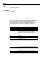
Syntax Description
type
Type of interface to be configured. See Table 10.
number
Port, connector, or interface card number. On a Cisco 4000 series router,
specifies the NPM number. The numbers are assigned at the factory at the
time of installation or when added to a system, and can be displayed with
the show interfaces command.
slot
Refer to the appropriate hardware manual for slot and port information.
port
Refer to the appropriate hardware manual for slot and port information.
port-adapter
Refer to the appropriate hardware manual for information about port
adapter compatibility.
:channel-group
The Cisco 4000 series routers specifies the T1 channel group number in
the range of 0 to 23 defined with the channel-group controller
configuration command. On a dual port card, it is possible to run
channelized on one port and primary rate on the other port.
The Cisco MC3810 specifies the T1/E1 channel group number in the
range of 0 to 23 defined with the channel-group controller configuration
command.
.subinterface-number
Subinterface number in the range 1 to 4294967293. The number that
precedes the period (.) must match the number to which this subinterface
belongs.
multipoint | point-to-point
(Optional) Specifies a multipoint or point-to-point subinterface. There is
no default.
Interface Commands IR-109
interface
Default
No interface types are configured.
Command Mode
Global configuration
Usage Guidelines
This command first appeared in Cisco IOS Release 10.0 for the Cisco 7000 series routers.
This command first appeared in Cisco IOS Release 11.0 for the Cisco 4000 series routers.
This command was changed in Cisco IOS Release 11.2 to add the posi keyword.
This command was changed in Cisco IOS Release 11.3 to change the posi keyword to pos.
This command was changed in Cisco IOS Release 12.0 to add the switch keyword.
Subinterfaces can be configured to support partially meshed Frame Relay networks. Refer to the part
entitled “Configuring Serial Interfaces” in the Cisco IOS Interface Configuration Guide.
There is no correlation between the number of the physical serial interface and the number of the
logical LAN Extender interface. These interfaces can have the same or different numbers.
Table 10
IR-110
Interface Type Keywords
Keyword
Interface Type
async
Port line used as an asynchronous interface.
atm
ATM interface.
bri
Integrated Services Digital Network (ISDN) Basic Rate Interface (BRI).
This interface configuration is propagated to each of the B channels.
B channels cannot be individually configured. The interface must be
configured with dial-on-demand commands in order for calls to be placed
on that interface.
dialer
Dialer interface.
ethernet
Ethernet IEEE 802.3 interface.
fastethernet
100-Mbps Ethernet interface on the Cisco 4500, Cisco 4700, Cisco 7000
and Cisco 7500 series routers.
fddi
Fiber Distributed Data Interface (FDDI).
group-async
Master asynchronous interface.
hssi
High-Speed Serial Interface (HSSI).
lex
LAN Extender (LEX) interface.
loopback
Software-only loopback interface that emulates an interface that is always
up. It is a virtual interface supported on all platforms. The interface-number
is the number of the loopback interface that you want to create or configure.
There is no limit on the number of loopback interfaces you can create.
null
Null interface.
port-channel
Port channel interface
pos
Packet OC-3 interface on the Packet over SONET Interface Processor
serial
Serial interface.
switch
Switch interface
Cisco IOS Interface Command Reference
interface
Table 10
Interface Type Keywords (continued)
Keyword
Interface Type
tokenring
Token Ring interface.
tunnel
Tunnel interface; a virtual interface. The number is the number of the
tunnel interface that you want to create or configure. There is no limit on
the number of tunnel interfaces you can create.
vg-anylan
100VG-AnyLAN port adapter
Examples
The following example configures serial interface 0 with PPP encapsulation:
interface serial 0
encapsulation ppp
The following example enables loopback mode and assigns an IP network address and network mask
to the interface. The loopback interface established here will always appear to be up:
interface loopback 0
ip address 131.108.1.1 255.255.255.0
The following example for the Cisco 7500 series router shows the interface configuration command
for Ethernet port 4 on the EIP that is installed in (or recently removed from) slot 2:
interface ethernet 2/4
The following example begins configuration on the Token Ring interface processor in slot 1 on
port 0 of a Cisco 7500 series routers:
interface tokenring 1/0
The following example shows how a partially meshed Frame Relay network can be configured. In
this example, subinterface serial 0.1 is configured as a multipoint subinterface with three Frame
Relay PVCs associated, and subinterface serial 0.2 is configured as a point-to-point subinterface.
interface serial 0
encapsulation frame-relay
interface serial 0.1 multipoint
ip address 131.108.10.1 255.255.255.0
frame-relay interface-dlci 42 broadcast
frame-relay interface-dlci 53 broadcast
interface serial 0.2 point-to-point
ip address 131.108.11.1 255.255.0
frame-relay interface-dlci 59 broadcast
The following example configures circuit 0 of a T1 link for Point-to-Point Protocol (PPP)
encapsulation:
controller t1 4/1
circuit 0 1
interface serial 4/1:0
ip address 131.108.13.1 255.255.255.0
encapsulation ppp
The following example configures LAN Extender interface 0:
interface lex 0
Interface Commands IR-111
interface
Related Commands
You can use the master indexes or search online to find documentation of related commands.
circuit
controller
mac-address
ppp
show interfaces
slip
IR-112
Cisco IOS Interface Command Reference
interface dialer
interface dialer
To designate a dialer rotary group leader, use the interface dialer global configuration command.
interface dialer interface-number
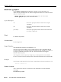
Syntax Description
interface-number
Integer that you select to indicate a dialer rotary group in the range 0 to 9.
Default
No dialer rotary group leader is specified.
Command Mode
Global configuration
Usage Guidelines
Dialer rotary groups allow you to apply a single interface configuration to a set of interfaces. Once
the interface configuration is propagated to a set of interfaces, those interfaces can be used to place
calls using the standard dial-on-demand criteria. When many destinations are configured, any of
these interfaces can be used for outgoing calls.
Dialer rotary groups are useful in environments that require many calling destinations. Only the
rotary group needs to be configured with all of the dialer map commands. The only configuration
required for the interfaces is the dialer rotary-group command that indicates which interface is part
of a dialer rotary group.
Although a dialer rotary group is configured as an interface, it is not a physical interface. Instead it
represents a group of interfaces. Any number of dialer groups can be defined.
Interface configuration commands entered after the interface dialer command will be applied to all
physical interfaces assigned to specified rotary group.
Example
The following example identifies dialer interface 1 as the dialer rotary group leader. Dialer
interface 1 is not a physical interface, but represents a group of interfaces. The interface
configuration commands that follow apply to all interfaces included in this group.
interface dialer 1
encapsulation ppp
dialer in-band
dialer map ip 172.30.2.5 username YYY 14155553434
dialer map ip 172.30.4.5 username ZZZ
Related Commands
You can use the master indexes or search online to find documentation of related commands.
dialer rotary-group
Interface Commands IR-113
interface fastethernet
interface fastethernet
To select a particular Fast Ethernet interface for configuration, use the interface fastethernet global
configuration command.
interface fastethernet number (Cisco 4500 and 4700 series routers)
interface fastethernet slot/port (Cisco 7200 series routers)
interface fastethernet slot/port-adapter/port (Cisco 7500 series routers)
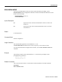
Syntax Description
number
Port, connector, or interface card number. On a Cisco 4500 or
4700 series routers, specifies the NIM or NPM number. The
numbers are assigned at the factory at the time of installation or
when added to a system.
slot
Refer to the appropriate hardware manual for slot and port
information.
port
Refer to the appropriate hardware manual for slot and port
information.
port-adapter
Refer to the appropriate hardware manual for information about
port adapter compatibility.
Default
Standard Advanced Research Projects Agency (ARPA) encapsulation is configured.
Command Mode
Global configuration
Usage Guidelines
This command first appeared in Cisco IOS Release 11.2.
Default encapsulation type changed to ARPA in Cisco IOS Release 11.3.
Examples
The following example configures Fast Ethernet interface 0 for standard ARPA encapsulation (the
default setting) on a Cisco 4500 or 4700 series routers:
interface fastethernet 0
Related Commands
You can use the master indexes or search online to find documentation of related commands.
show interfaces fastethernet
IR-114
Cisco IOS Interface Command Reference
interface group-async
interface group-async
To create a group interface that will serve as master, to which asynchronous interfaces can be
associated as members, use the interface group-async global configuration command. Use the no
form of the command to restore the default.
interface group-async unit-number
no interface group-async unit-number
Syntax Description
unit-number
The number of the asynchronous group interface being created.
Default
No interfaces are designated as group masters.
Command Mode
Global configuration
Usage Guidelines
Using the interface group-async command, you create a single asynchronous interface to which
other interfaces are associated as members using the group-range command. This one-to-many
configuration allows you to configure all associated member interfaces by entering one command on
the group master interface, rather than entering this command on each individual interface. You can
create multiple group masters on a device; however, each member interface can only be associated
with one group.
Examples
The following example defines asynchronous group master interface 0:
interface group-async 0
Related Commands
You can use the master indexes or search online to find documentation of related commands.
group-range
member
Interface Commands IR-115
interface port-channel
interface port-channel
To specify a Fast EtherChannel and enter interface configuration mode, use the interface
port-channel global configuration command.
interface port-channel channel-number
Syntax Description
channel-number
Channel number assigned to this port-channel interface. Range
is 1 to 4.
Default
No Fast EtherChannel is specified.
Command Mode
Global configuration
Usage Guidelines
This command first appeared in Cisco IOS Release 11.1 CA.
The Fast EtherChannel feature allows multiple Fast Ethernet point-to-point links to be bundled into
one logical link to provide bidirectional bandwidth of up to 800 Mbps. Fast EtherChannel can be
configured between Cisco 7000 and 7500 series routers with the 7000 Series Route Switch Processor
(RSP7000) and 7000 Series Chassis Interface (RSP7000CI), or between a Cisco 7000 or 7500 series
router with the RSP7000 and RSP700CI and a Catalyst 5000 switch.
You can configure the port-channel interface as you would do to any Fast Ethernet interface.
After you create a port-channel interface, you assign Fast Ethernet interfaces (up to four) to it. For
information on how to assign a Fast Ethernet interface to a port-channel interface, refer to the
channel-group interface configuration command.
Caution The port-channel interface is the routed interface. Do not enable Layer 3 addresses on the physical
Fast Ethernet interfaces. Do not assign bridge groups on the physical Fast Ethernet interfaces because it
creates loops. Also, you must disable spanning tree.
Note If you configure ISL, you must assign the IP address to the subinterface (for example,
interface port-channel 1.1—an IP address per VLAN) and you must specify the encapsulation with
VLAN number under that subinterface (for example, encapsulation isl 100) for ISL to work.
Note Currently, if you want to use the Cisco Discovery Protocol (CDP), you must configure it only
on the port-channel interface and not on the physical Fast Ethernet interface.
IR-116
Cisco IOS Interface Command Reference
interface port-channel
Note If you do not assign a static MAC address on the port-channel interface, the Cisco IOS
software automatically assigns a MAC address. If you assign a static MAC address and then later
remove it, the Cisco IOS software automatically assigns a MAC address.
Caution With Release 11.1(20)CC, the Fast EtherChannel supports CEF/dCEF. We recommend that you
clear all explicit ip route-cache distributed commands from the Fast Ethernet interfaces before enabling
dCEF on the port-channel interface. Doing this gives the port-channel interface proper control of its physical
Fast Ethernet links. When you enable CEF/dCEF globally, all interfaces that support CEF/dCEF are enabled.
When CEF/dCEF is enabled on the port-channel interface, it is automatically enabled on each of the Fast
Ethernet interfaces in the channel group. However, if you have previously disabled CEF/dCEF on the Fast
Ethernet interface, CEF/dCEF is not automatically enabled. In this case, you must enable CEF/dCEF on the
Fast Ethernet interface.
Example
The following example creates a port-channel interface with a channel group number of 1 and adds
three Fast Ethernet interfaces to port-channel 1:
Router(config)# interface port-channel
Router(config-if)# ip address 1.1.1.10
Router(config)# interface fastethernet
Router(config-if)# channel-group 1
Router(config)# interface fastethernet
Router(config-if)# channel-group 1
Router(config)# interface fastethernet
Router(config-if)# channel-group 1
1
255.255.255.0
1/0/0
4/0/0
5/0/0
Related Commands
You can use the master indexes or search online to find documentation of related commands.
channel-group
show interfaces port-channel
Interface Commands IR-117
interface vg-anylan
interface vg-anylan
Use the interface vg-anylan global configuration command to specify the interface on a
100VG-AnyLAN port adapter and enter interface configuration mode on Cisco 7200 series routers
and Cisco 7500 series routers.
interface vg-anylan slot/port-adapter/port (VIP cards in Cisco 7500 series routers)
interface vg-anylan slot/port (Cisco 7200 series routers)
Syntax Description
slot
Refer to the appropriate hardware manual for slot and port
information.
port
Refer to the appropriate hardware manual for slot and port
information.
port-adapter
Refer to the appropriate hardware manual for information about
port adapter compatibility.
Default
No interfaces are specified.
Command Mode
Global configuration
Usage Guidelines
This command first appeared in Cisco IOS Release 11.3.
The 100VG-AnyLAN port adapter provides a single interface port that is compatible with and
specified by IEEE 802.12. The 100VG-AnyLAN port adapter provides 100 Mbps over Category 3
or Category 5 unshielded twisted-pair (UTP) cable with RJ-45 terminators, and supports
IEEE 802.3 Ethernet packets.
You configure the 100VG-AnyLAN port adapter as you would any Ethernet or Fast Ethernet
interface. The 100VG-AnyLAN port adapter can be monitored with the IEEE 802.12 Interface MIB.
Example
The following example specifies the 100VG-AnyLAN port adapter in the first port adapter in slot 1:
interface vg-anylan 1/0/0
Related Commands
You can use the master indexes or search online to find documentation of related commands.
frame-type
show interfaces vg-anylan
IR-118
Cisco IOS Interface Command Reference
international bit
international bit
To set the E3 international bit in the G.751 frame used by the PA-E3 port adapter, use the
international bit interface configuration command. To return to the default international bit, use the
no form of this command.
international bit {0 | 1} {0 | 1}
no international bit
Syntax Description
0|1
Specifies the value of the first international bit in the G.751 frame. The
default is 0.
0|1
Specifies the value of the second international bit in the G.751 frame.
The default is 0.
Default
0 0 international bit
Command Mode
Interface configuration
Usage Guidelines
This command first appeared in Cisco IOS Release 11.1 CA.
The international bit command sets bits 6 and 8, respectively, of set II in the E3 frame.
To verify the international bit configured on the interface, use the show controller serial EXEC
command.
Example
The following example sets the international bit to 1 1 on the PA-E3 port adapter in slot 1,
port-adapter slot 0, interface 0:
interface serial 1/0/0
international bit 1 1
Related Commands
You can use the master indexes or search online to find documentation of related commands.
national bit
show controllers serial
Interface Commands IR-119
invert data
invert data
To invert the data stream, use the invert data interface configuration command. This command
applies only to the Cisco 7000 series routers with the RSP7000 and RSP7000CI, Cisco 7200 series
routers, and Cisco 7500 series routers. Use the no form of this command to disable inverting the data
stream.
invert data
no invert data
Syntax Description
This command has no arguments or keywords.
Default
Data is not inverted.
Command Mode
Interface configuration
Usage Guidelines
This command first appeared in Cisco IOS Release 11.1 CA and Release 11.2 P.
T1 Line without B8ZS Encoding
If the interface on the PA-8T and PA-4T+ synchronous serial port adapters and the PA-T3 and
PA-2T3 synchronous serial port adapters is used to drive a dedicated T1 line that does not have B8ZS
encoding (a method to avoid 15 zeros), the data stream must be inverted (both TXD and RXD) either
in the connecting CSU/DSU or the interface.
Inverting is a method of avoiding excessive zeroes that is superseded by the use of B8ZS encryption.
This option could be needed for use with legacy equipment that supports this option. By inverting
the HDLC data stream, the HDLC zero insertion algorithm becomes a ones insertion algorithm that
satisfies the T1 requirements. Be careful not to invert data both on the interface and on the CSU/DSU
as two data inversions will cancel each other out.
AMI Line Coding
If the interface on the CT3IP uses AMI line coding, you must also invert the data on the T1 channel.
For more information, see the t1 linecode controller configuration command.
Example
The following example inverts data on serial interface 3/1/0:
interface serial 3/1/0
invert data
IR-120
Cisco IOS Interface Command Reference
invert data
Related Commands
You can use the master indexes or search online to find documentation of related commands.
t1 linecode
Interface Commands IR-121
invert rxclock
invert rxclock
To configure UIO serial port 0 or 1 on the Cisco MC3810 when the cable connected is DCE type,
use the invert rxclock interface configuration command. The command inverts the phase of the RX
clock on the UIO serial interface, which does not use the T1/E1 interface. To disable the phase
inversion, use the no form of this command.
invert rxclock
no invert rxclock
Syntax Description
This command has no arguments or keywords.
Default
Receive clock signal is not inverted.
Command Mode
Interface configuration
Usage Guidelines
This command first appeared in Cisco IOS Release 11.3 MA.
Example
The following example inverts the clock signal on serial interface 1:
interface serial 1
invert rxclock
IR-122
Cisco IOS Interface Command Reference
invert-transmit-clock
invert-transmit-clock
The invert txclock command replaces this command. Refer to the description of invert txclock for
information on the transmit clock signal.
Interface Commands IR-123
invert txclock
invert txclock
Use the invert txclock interface configuration command to invert the transmit clock signal. Delays
between the SCTE clock and data transmission indicate that the transmit clock signal might not be
appropriate for the interface rate and length of cable being used. Different ends of the wire can have
variances that differ slightly.The invert txclock command compensates for these variances. This
command replaces the invert-transmit-clock command.
This command applies only to Cisco 7200 series and Cisco 7500 series routers. To return to the
transmit clock signal to its initial state, use the no form of this command.
invert txclock
no invert txclock
Syntax Description
This command has no arguments or keywords.
Default
Transmit clock signal is not inverted.
Command Mode
Interface configuration
Usage Guidelines
This command first appeared in Cisco IOS Release 10.0.
This command was modified in Cisco IOS Release 11.3 to change the command from
invert-transmit-clock to invert txclock.
Systems that use long cables or cables that are not transmitting the TxC signal (transmit echoed
clock line, also known as TXCE or SCTE clock) can experience high error rates when operating at
the higher transmission speeds. For example, if a PA-8T synchronous serial port adapter is reporting
a high number of error packets, a phase shift might be the problem. Inverting the clock might correct
this shift.
When a PA-8T or PA-4T+ port adapter interface is DTE, the invert txclock command inverts the
TxC signal it received from the remote DCE. When the PA-8T or PA-4T+ port adapter interface is
DCE, this command changes the signal back to its original phase.
Example
The following example inverts the clock signal on serial interface 3/0:
interface serial 3/0
invert txclock
IR-124
Cisco IOS Interface Command Reference
keepalive
keepalive
To set the keepalive timer for a specific interface, use the keepalive interface configuration
command. To turn off keepalives entirely, use the no form of this command.
keepalive [seconds]
no keepalive [seconds]
Syntax Description
seconds
(Optional) Unsigned integer value greater than 0. The
default is 10 seconds.
Default
10 seconds
Command Mode
Interface configuration
Usage Guidelines
This command first appeared in Cisco IOS Release 10.0.
You can configure the keepalive interval, which is the frequency at which the Cisco IOS software
sends messages to itself (Ethernet and Token Ring) or to the other end (serial), to ensure a network
interface is alive. The interval in previous software versions was 10 seconds; it is now adjustable in
1-second increments down to 1 second. An interface is declared down after three update intervals
have passed without receiving a keepalive packet.
Setting the keepalive timer to a low value is very useful for rapidly detecting Ethernet interface
failures (transceiver cable disconnecting, cable unterminated, and so on).
A typical serial line failure involves losing Carrier Detect (CD) signal. Because this sort of failure is
typically noticed within a few milliseconds, adjusting the keepalive timer for quicker routing
recovery is generally not useful.
Note When adjusting the keepalive timer for a very low bandwidth serial interface, large datagrams
can delay the smaller keepalive packets long enough to cause the line protocol to go down. You may
need to experiment to determine the best value.
Example
The following example sets the keepalive interval to 3 seconds:
interface ethernet 0
keepalive 3
Interface Commands IR-125
lex burned-in-address
lex burned-in-address
To set the burned-in MAC address for a LAN Extender interface, use the lex burned-in-address
interface configuration command. To clear the burned-in MAC address, use the no form of this
command.
lex burned-in-address ieee-address
no lex burned-in-address
Syntax Description
ieee-address
48-bit IEEE MAC address written as a dotted triplet of
four-digit hexadecimal numbers.
Default
No burned-in MAC address is set.
Command Mode
Interface configuration
Usage Guidelines
This command first appeared in Cisco IOS Release 10.3.
Use this command only on a LAN Extender interface that is not currently active (not bound to a serial
interface).
Example
The following example sets the burned-in MAC address on LAN Extender interface 0:
interface serial 4
encapsulation ppp
interface lex 0
lex burned-in-address 0000.0c00.0001
ip address 131.108.172.21 255.255.255.0
IR-126
Cisco IOS Interface Command Reference
lex input-address-list
lex input-address-list
To assign an access list that filters on MAC addresses, use the lex input-address-list interface
configuration command. To remove an access list from the interface, use the no form of this
command.
lex input-address-list access-list-number
no lex input-address-list
Syntax Description
access-list-number
Number of the access list you assigned with the access-list
global configuration command. It can be a number from 700
to 799.
Default
No access lists are preassigned to a LAN Extender interface.
Command Mode
Interface configuration
Usage Guidelines
This command first appeared in Cisco IOS Release 10.3.
The no lex input-address-list command first appeared in Cisco IOS Release 10.0.
Use the lex input-address-list command to filter the packets that are allowed to pass from the LAN
Extender to the core router. The access list filters packets based on the source MAC address.
The LAN Extender interface does not process MAC-address masks. Therefore, you should omit the
mask from the access-list commands.
For LAN Extender interfaces, an implicit permit everything entry is automatically defined at the end
of an access list. Note that this default differs from other access lists, which have an implicit deny
everything entry at the end of each access list.
Example
The following example applies access list 710 to LAN Extender interface 0. This access list denies
all packets from MAC address 0800.0214.2776 and permits all other packets.
access-list 710 deny 0800.0214.2776
interface lex 0
lex input-address-list 710
Related Commands
You can use the master indexes or search online to find documentation of related commands.
access-list
Interface Commands IR-127
lex input-type-list
lex input-type-list
Use the lex input-type-list interface configuration command to assign an access list that filters
Ethernet packets by type code. To remove an access list from the interface, use the no form of this
command.
lex input-type-list access-list-number
no lex input-type-list
Syntax Description
access-list-number
Number of the access list you assigned with the access-list
global configuration command. It can be a number in the range
200 to 299.
Default
No access lists are preassigned to a LAN Extender interface.
Command Mode
Interface configuration
Usage Guidelines
This command first appeared in Cisco IOS Release 10.3.
Filtering is done on the LAN Extender chassis.
The LAN Extender interface does not process masks. Therefore, you should omit the mask from the
access-list commands.
For LAN Extender interfaces, an implicit permit everything entry is automatically defined at the end
of an access list. Note that this default differs from other access lists, which have an implicit deny
everything entry at the end of each access list.
Example
The following example applies access list 220 to LAN Extender interface 0. This access list denies
all AppleTalk packets (packets with a type field of 0x809B) and permits all other packets.
access-list 220 deny 0x809B 0x0000
interface lex 0
lex input-type-list 220
Related Commands
You can use the master indexes or search online to find documentation of related commands.
access-list
IR-128
Cisco IOS Interface Command Reference
lex priority-group
lex priority-group
Use the lex priority-group interface configuration command to activate priority output queuing on
the LAN Extender. To disable priority output queuing, use the no form of this command.
lex priority-group group
no lex priority-group
Syntax Description
group
Number of the priority group. It can be a number in the range 1 to 10.
Default
Disabled
Command Mode
Interface configuration
Usage Guidelines
This command first appeared in Cisco IOS Release 10.3.
To define queuing priorities, use the priority-list protocol global configuration command. Note that
you can use only the following forms of this command:
priority-list list protocol protocol {high | medium | normal | low}
priority-list list protocol bridge {high | medium | normal | low} list list-number
If you specify a protocol that does not have an assigned Ethernet type code, such as x25, stun, or
pad, it is ignored and will not participate in priority output queuing.
Example
The following example activates priority output queuing on LAN Extender interface 0:
priority-list 5 protocol bridge medium list 701
lex interface 0
lex priority-group 5
Related Commands
You can use the master indexes or search online to find documentation of related commands.
priority-list protocol
Interface Commands IR-129
lex retry-count
lex retry-count
Use the lex retry-count interface configuration command to define the number of times to resend
commands to the LAN Extender chassis. To return to the default value, use the no form of this
command.
lex retry-count number
no lex retry-count [number]
Syntax Description
number
Number of times to retry sending commands to the LAN
Extender. It can be a number in the range 0 to 100. The default
is 10 times.
Default
10
Command Mode
Interface configuration
Usage Guidelines
This command first appeared in Cisco IOS Release 10.3.
After the router has sent a command the specified number of times without receiving an
acknowledgment from the LAN Extender, it stops sending the command altogether.
Example
The following example resends commands 20 times to the LAN Extender:
lex interface 0
lex retry-count 20
Related Commands
You can use the master indexes or search online to find documentation of related commands.
lex timeout
IR-130
Cisco IOS Interface Command Reference
lex timeout
lex timeout
Use the lex timeout interface configuration command to define the amount of time to wait for a
response from the LAN Extender. To return to the default time, use the no form of this command.
lex timeout milliseconds
no lex timeout [milliseconds]
Syntax Description
milliseconds
Time, in milliseconds, to wait for a response from the LAN
Extender before resending the command. It can be a number in
the range 500 to 60000. The default is 2000 milliseconds
(2 seconds).
Default
2000 milliseconds (2 seconds)
Command Mode
Interface configuration
Usage Guidelines
This command first appeared in Cisco IOS Release 10.3.
The lex timeout command defines the amount of time that the router waits to receive an
acknowledgment after having sent a command to the LAN Extender.
Example
The following example causes unacknowledged packets to be resent at 4-second intervals:
lex interface 0
lex timeout 4000
Related Commands
You can use the master indexes or search online to find documentation of related commands.
lex retry-count
Interface Commands IR-131
linecode
linecode
Use the linecode controller configuration command to select the line-code type for T1 or E1 line.
linecode {ami | b8zs | hdb3}
Syntax Description
ami
Specifies alternate mark inversion (AMI) as the line-code type. Valid for T1 or
E1 controllers.
b8zs
Specifies B8ZS as the line-code type. Valid for T1 controller only.
hdb3
Specifies high-density bipolar 3 (hdb3) as the line-code type. Valid for E1
controller only.
Defaults
AMI is the default for T1 lines.
High-density bipolar 3 is the default for E1 lines.
Command Mode
Controller configuration
Usage Guidelines
This command first appeared in Cisco IOS Release 10.3.
Use this command in configurations where the router or access server must communicate with T1
fractional data lines. The T1 service provider determines which line-code type, either ami or b8zs,
is required for your T1 circuit. Likewise, the E1 service provider determines which line-code type,
either ami or hdb3, is required for your E1 circuit.
Example
The following example specifies B8ZS as the line-code type:
linecode b8zs
IR-132
Cisco IOS Interface Command Reference
link-test
link-test
To reenable the link-test function on a port on an Ethernet hub of a Cisco 2505 or Cisco 2507, use
the link-test hub configuration command. Use the no form of this command to disable this feature
if a pre-10BaseT twisted-pair device not implementing link test is connected to the hub port.
link-test
no link-test
Syntax Description
This command has no arguments or keywords.
Default
Enabled
Command Mode
Hub configuration
Usage Guidelines
This command first appeared in Cisco IOS Release 10.3.
This command applies to a port on an Ethernet hub only. Disable this feature if a 10BaseT
twisted-pair device at the other end of the hub does not implement the link test function.
Example
The following example disables the link test function on hub 0, ports 1 through 3:
hub ethernet 0 1 3
no link-test
Related Commands
You can use the master indexes or search online to find documentation of related commands.
hub
Interface Commands IR-133
local-lnm
local-lnm
To enable Lanoptics Hub Networking Management of a PCbus Token Ring interface, use the
local-lnm interface configuration command. Use the no form of this command to disable Lanoptics
Hub Networking Management.
local-lnm
no local-lnm
Syntax Description
This command has no arguments or keywords.
Default
Management is not enabled.
Command Mode
Interface configuration
Usage Guidelines
This command first appeared in Cisco IOS Release 10.3.
The Token Ring interface on the AccessPro PC card can be managed by a remote LAN manager over
the PCbus interface. At present, the Lanoptics Hub Networking Management software running on
an IBM compatible PC is supported.
Example
The following example enables Lanoptics Hub Networking Management:
local-lnm
IR-134
Cisco IOS Interface Command Reference
loopback (interface)
loopback (interface)
To diagnose equipment malfunctions between interface and device, use the loopback interface
configuration command. The no form of this command disables the test.
loopback
no loopback
Syntax Description
This command has no arguments or keywords.
Default
Disabled
Command Mode
Interface configuration
Usage Guidelines
This command first appeared in Cisco IOS Release 10.0.
On HSSI serial interface cards, the loopback function configures a two-way internal and external
loop on the HSA applique of the specific interface.
On MCI and SCI serial interface cards, the loopback functions when a CSU/DSU or equivalent
device is attached to the router or access server. The loopback command loops the packets through
the CSU/DSU to configure a CSU loop, when the device supports this feature.
On the MCI and MEC Ethernet cards, the interface receives back every packet it sends when the
loopback command is enabled. Loopback operation has the additional effect of disconnecting
network server functionality from the network.
On the CSC-FCI FDDI card, the interface receives back every packet it sends when the loopback
command is enabled. Loopback operation has the additional effect of disconnecting network server
functionality from the network.
On all Token Ring interface cards (except the 4-megabit CSC-R card), the interface receives back
every packet it sends when the loopback command is enabled. Loopback operation has the
additional effect of disconnecting network server functionality from the network.
Note Loopback does not work on an X.21 DTE because the X.21 interface definition does not
include a loopback definition.
To show interfaces currently in loopback operation, use the show interfaces loopback EXEC
command.
Example
The following example configures the loopback test on Ethernet interface 4:
interface ethernet 4
loopback
Interface Commands IR-135
loopback (interface)
Related Commands
You can use the master indexes or search online to find documentation of related commands.
down-when-looped
show interfaces loopback
IR-136
Cisco IOS Interface Command Reference
loopback (E3/T3 interface)
loopback (E3/T3 interface)
To loop the serial interface on a PA-E3 or a PA-T3 port adapter, use the loopback interface
configuration command. To remove the loopback, use the no form of this command.
loopback {dte | local | network {line | payload}} (PA-E3)
loopback {dte | local | network {line | payload} | remote} (PA-T3)
no loopback
Syntax Description
dte
Sets the loopback after the LIU toward the terminal.
local
Sets the loopback after going through the framer toward the
terminal.
network {line | payload}
Sets the loopback toward the network before going through the
framer (line) or after going through the framer (payload).
remote
Sends a far-end alarm control (FEAC) to set the remote framer
in loopback.
Default
Disabled
Command Mode
Interface configuration
Usage Guidelines
This command first appeared in Cisco IOS Release 11.1 CA.
Use this command for troubleshooting purposes.
To verify that a loopback is configured on the interface, use the show interface serial or show
interfaces loopback EXEC command.
Example
The following example configures the serial interface located in slot 3/0/0 for a local loopback:
interface serial 3/0/0
loopback local
Related Commands
You can use the master indexes or search online to find documentation of related commands.
show controllers serial
Interface Commands IR-137
loopback (T1 interface)
loopback (T1 interface)
To loop individual T1 channels on the Channelized T3 Interface Processor (CT3IP) in Cisco 7000
series routers with the RSP7000 and RSP7000CI and in Cisco 7500 series routers, use the loopback
interface configuration command. Use the no form of this command to remove the loopback.
loopback [local | network {line | payload} | remote {line {fdl {ansi | bellcore} | inband} |
payload [fdl] [ansi]}]
no loopback
Syntax Description
local
(Optional) Loops the router output data back toward the router
at the T1 framer and sends an AIS signal out toward the
network.
network {line | payload}
(Optional) Loops the data back toward the network before the
T1 framer and automatically sets a local loopback at the HDLC
controllers (line) or loops the payload data back toward the
network at the T1 framer and automatically sets a local
loopback at the HDLC controllers (payload).
remote line fdl {ansi |
bellcore}
(Optional) Sends a repeating, 16-bit ESF data link code word
(00001110 11111111 for FDL ANSI and 00010010 11111111
for FDL Bellcore) to the remote end requesting that it enter into
a network line loopback. Specify the ansi keyword to enable the
remote line Facility Data Link (FDL) ANSI bit loopback on the
T1 channel, per the ANSI T1.403 Specification. Specify the
bellcore keyword to enable the remote SmartJack loopback on
the T1 channel, per the TR-TSY-000312 Specification.
remote line inband
(Optional) Sends a repeating, 5-bit inband pattern (00001) to the
remote end requesting that it enter into a network line loopback.
remote payload [fdl] [ansi]
(Optional) Sends a repeating, 16-bit ESF data link code word
(00010100 11111111) to the remote end requesting that it enter
into a network payload loopback. Enables the remote payload
Facility Data Link (FDL) ANSI bit loopback on the T1 channel.
You can optionally specify fdl and ansi, but it is not necessary.
Default
Disabled
Command Mode
Interface configuration
Usage Guidelines
This command first appeared in Cisco IOS Release 11.1 CA.
Use this command for troubleshooting purposes.
IR-138
Cisco IOS Interface Command Reference
loopback (T1 interface)
To better diagnose T1 provisioning problems, you can place the the remote CSU or remote
SmartJack into loopback. The loopback remote line fdl interface configuration command allows
you to place either the CSU or the SmartJack into loopback:
•
•
ansi—Places the CSU into loopback, per the ANSI T1.403 Specification
bellcore—Places the SmartJack into loopback, per the TR-TSY-000312 Specification
When both are configured, transmission of LOF indication (yellow alarm) takes priority over
transmission of some FDL messages.
If the remote loopback appears not to be working, use the show cont t3 command to determine if
the given T1 is currently attempting to transmit a LOF indication (yellow alarm):
Router# show controllers t3 0/0/0:2
T3 0/0/0 is up.
CT3 H/W Version: 5, CT3 ROM Version: 1.2, CT3 F/W Version: 2.5.9
Mx H/W version: 2, Mx ucode ver: 1.34
T1 2 is down, speed: 1536 kbs, non-inverted data
timeslots: 1-24
FDL per AT&T 54016 spec.
Transmitter is sending LOF Indication.
Receiver is getting AIS.
If the transmitter is sending a LOF indication, as in the previous example, stop the transmission of
the LOF indication (yellow alarm) with the no t1 yellow generation configuration command as
shown in the following example:
Router(config)# controllers t3 0/0/0
Router(config-controll)# no t1 2 yellow generation
Router(config-controll)# ^D
To verify that the transmission of the LOF indication (yellow alarm) has stopped, use the
show cont t3 command:
Router# show cont t3 0/0/0:2
T3 0/0/0 is up.
CT3 H/W Version: 5, CT3 ROM Version: 1.2, CT3 F/W Version: 2.5.9
Mx H/W version: 2, Mx ucode ver: 1.34
T1 2 is down, speed: 1536 kbs, non-inverted data
timeslots: 1-24
FDL per AT&T 54016 spec.
Receiver is getting AIS.
Framing is ESF, Line Code is B8ZS, Clock Source is Internal.
Yellow Alarm Generation is disabled
Then retry the remote loopback command. When diagnosis is complete, remember to re-enable the
LOF indication (yellow alarm).
You can also loopback all the T1 channels by using the loopback (CT3IP) interface configuration
command.
Example
The following example configures T1 channel 5 for a local loopback:
interface serial 3/0/0:5
loopback local
Interface Commands IR-139
loopback (T1 interface)
Related Commands
You can use the master indexes or search online to find documentation of related commands.
loopback (T3)
IR-140
Cisco IOS Interface Command Reference
loopback (T3 controller)
loopback (T3 controller)
To loop the entire T3 (all 28 T1 channels) on the Channelized T3 Interface Processor (CT3IP) in
Cisco 7500 series routers, use the loopback controller configuration command. Use the no form of
this command to remove the loopback.
loopback [local | network | remote]
no loopback
Syntax Description
local
(Optional) Loops the data back toward the router and sends an
AIS signal out toward the network.
network
(Optional) Loops the data toward the network at the T1 framer.
remote
(Optional) Sends a far-end alarm control (FEAC) request to the
remote end requesting that it enter into a network line loopback.
FEAC requests (and therefore remote loopbacks) are only
possible when the T3 is configured for C-bit framing. The type
of framing used is determined by the equipment you are
connecting to (for more information, see the framing controller
command).
Default
Disabled
Command Mode
Controller configuration
Usage Guidelines
This command first appeared in Cisco IOS Release 11.3.
Use this command for troubleshooting purposes.
You can also loopback each T1 channel by using the loopback interface configuration command.
For more information, refer to the “Troubleshoot the T3 and T1 Channels” section in the
“Configuring Serial Interfaces” chapter of the Cisco IOS Interface Configuration Guide.
Example
The following example configures the CT3IP for a local loopback:
controller t3 3/0/0
loopback local
Related Commands
You can use the master indexes or search online to find documentation of related commands.
loopback remote (interface)
Interface Commands IR-141
loopback applique
loopback applique
To configure an internal loop on the HSSI applique, use the loopback interface configuration
command. To remove the loop, use the no form of this command.
loopback applique
no loopback applique
Syntax Description
This command has no arguments or keywords.
Default
Disabled
Command Mode
Interface configuration
Usage Guidelines
This command first appeared in Cisco IOS Release 10.0.
This command loops the packets within the applique, to provide a way to test communication within
the router or access server. It is useful for sending pings to yourself to check functionality of the
applique.
To show interfaces currently in loopback operation, use the show interfaces loopback EXEC
command.
Example
The following example configures the loopback test on the HSSI applique:
interface serial 1
loopback applique
Related Commands
You can use the master indexes or search online to find documentation of related commands.
show interfaces loopback
IR-142
Cisco IOS Interface Command Reference
loopback dte
loopback dte
To loop packets back to the DTE from the CSU/DSU, when the device supports this feature, use the
loopback interface configuration command. To remove the loop, use the no form of this command.
loopback dte
no loopback dte
Syntax Description
This command has no arguments or keywords.
Default
Disabled
Command Mode
Interface configuration
Usage Guidelines
This command first appeared in Cisco IOS Release 10.0.
This command is useful for testing the DTE-to-DCE cable.
This command is used to test the performance of the integrated CSU/DSU. Packets are looped from
within the CSU/DSU back to the serial interface of the router. Send a test ping to see if the packets
successfully looped back. To cancel the loopback test, use the no loopback dte command.
When using the 4-wire 56/64-kbps CSU/DSU module, an out-of-service signal is transmitted to the
remote CSU/DSU.
To show interfaces currently in loopback operation, use the show interfaces loopback EXEC
command.
Example
The following example configures the loopback test on the DTE interface:
router(config)# interface serial 0
router(config-if)# loopback dte
router(config-if)#
Related Commands
You can use the master indexes or search online to find documentation of related commands.
show interfaces loopback
Interface Commands IR-143
loopback line
loopback line
Use the loopback line interface configuration command, to loop packets completely through the
CSU/DSU to configure the CSU loop. To remove the loop, use the no form of this command.
loopback line [payload]
no loopback line [payload]
Syntax Description
payload
(Optional) Configures a loopback point at the DSU and loops back data to the
network on an integrated CSU/DSU.
Default
Disabled
Command Mode
Interface configuration
Usage Guidelines
This command first appeared in Cisco IOS Release 10.0.
This command is useful for testing the DCE device (CSU/DSU) itself. When the loopback line
command is configured on the 2-wire 56-kbps CSU/DSU module or the 4-wire 56/64-kbps
CSU/DSU modules, the network data loops back at the CSU and the router data loops back at the
DSU. If the CSU/DSU is configured for switched mode, you must have an established connection to
perform a payload-line loopback. To loop the received data through the minimum amount of
CSU/DSU circuitry, issue the loopback line command.
When you issue the loopback line payload command on an integrated CSU/DSU module, the router
cannot transmit data through the serial interface for the duration of the loopback. Choosing the DSU
as a loopback point loops the received-network data through the maximum amount of CSU/DSU
circuitry. Data is not looped back to the serial interface. An active connection is required when
operating in switched mode for payload loopbacks.
If you enable the loopback line command on the fractional T1/T1 module, the CSU/DSU performs
a full-bandwidth loopback through the CSU portion of the module and data transmission through the
serial interface is interrupted for the duration of the loopback. No reframing or corrections of bipolar
violation errors or cyclic redundancy check (CRC) errors are performed. When you configure the
loopback line payload command on the FT1/T1 module, the CSU/DSU performs a loopback
through the DSU portion of the module. The loopback line payload command reframes the data
link, regenerates the signal, and corrects bipolar violations and Extended Super Frame CRC errors.
When performing a T1-line loopback with Extended Super Frame, communication over the facilities
data link is interrupted, but performance statistics are still updated. To show interfaces currently in
loopback operation, use the show service-module EXEC command.
To show interfaces currently in loopback operation on other routers, use the show interfaces
loopback EXEC command.
IR-144
Cisco IOS Interface Command Reference
loopback line
Examples
The following example configures the loopback test on the DCE device:
interface serial 1
loopback line
The following example shows how to configure a payload loopback on a Cisco 2524 or 2525 router:
Router1(config-if)#loopback line payload
Loopback in progress
Router1(config-if)#no loopback line
The following example shows the output on a Cisco 2524 or 2525 router when you loop a packet in
switched mode without an active connection:
Router1(config-if)#service-module 56k network-type switched
Router1(config-if)#loopback line payload
Need active connection for this type of loopback
% Service module configuration command failed: WRONG FORMAT.
Related Commands
You can use the master indexes or search online to find documentation of related commands.
show interfaces loopback
Interface Commands IR-145
loopback remote (interface)
loopback remote (interface)
To loop packets through a CSU/DSU, over a DS-3 link or a channelized T1 link, to the remote
CSU/DSU and back, use the loopback remote interface configuration command. To remove the
loopback, use the no form of this command.
loopback remote {full | payload | smart-jack} [0in1 | 1in1 | 1in2 | 1in5 | 1in8 | 3in24 | qrw |
user-pattern 24bit-binary value]
no loopback remote {full | payload | smart-jack}
loopback remote [2047 | 511 | stress-pattern pattern number]
no loopback remote
Note The keywords full, payload, smart-jack, 0in1 through 3in24, qrw, and user-pattern
24bit-binary value apply to the fractional T1/T1 CSU/DSU module. The keywords 2047, 511, and
stress-pattern apply to the 2- and 4-wire 56/64-kbps CSU/DSU module. The features for each
module are grouped and described in the following two syntax descriptions.
Syntax Description for FT1/T1 CSU/DSU Modules
IR-146
full
Transmit a full-bandwidth line loopback request to a remote device, which is
used for testing.
payload
Transmits a payload line loopback request to a remote device, which is used for
testing the line and remote DSU.
smart-jack
Transmits a loopback request to the remote smart-jack, which some service
providers attach on the line before the customer premises equipment (CPE).
You cannot put the local smart-jack into loopback.
0in1
(Optional) Transmits an all-zeros test pattern used for verifying B8ZS line
encoding. The remote end my report a loss of signal when using alternate mark
inversion (AMI) line coding.
1in1
(Optional) Transmits an all-ones test pattern used for signal power
measurements.
1in2
(Optional) Transmits an alternating ones and zeroes test pattern used for testing
bridge taps.
1in5
(Optional) Transmits the industry standard test-pattern loopback request.
1in8
(Optional) Transmits a test pattern used for stressing timing recovery of
repeaters.
3in24
(Optional) Transmits a test pattern used for testing the ones density tolerance
on AMI lines.
qrw
(Optional) Transmits a quasi-random word test pattern, which is a random
signal that simulates user data.
user-pattern
24bit-binary
value
(Optional) Transmits a test pattern that you define. Enter a binary string up to
24 bits long. For the fixed patterns such 0in1 and 1in1, the T1 framing bits are
jammed on top of the test pattern; for the user-pattern, the pattern is simply
repeated in the timeslots.
Cisco IOS Interface Command Reference
loopback remote (interface)
Syntax Description for 2- and 4-Wire, 56/64-kbps CSU/DSU Modules
2047
Transmits a pseudo-random test pattern that repeats after 2047 bits.
511
Transmits a pseudo-random test pattern that repeats after 511 bits.
stress-pattern
pattern number
Transmits a DDS stress pattern available only on the 4-wire 56/64-kbps
CSU/DSU module. You may enter a stress pattern from 1 to 4. A 1 pattern
sends 100 bytes of all 1s and then 100 bytes of all 0s to test the stress
clocking of the network. A 2 pattern sends 100 bytes of a 0x7e pattern then
100 bytes of all 0s. A 3 pattern sends continuous bytes of a 0x46 pattern. A 4
pattern sends continuous bytes of 0x02 pattern.
Default
Disabled
Command Mode
Interface configuration
Usage Guidelines
This command first appeared in Cisco IOS Release 11.0.
This command applies only when the remote CSU/DSU device is configured for this function. It is
used for testing the data communication channels along with or without remote CSU/DSU circuitry.
The loopback is usually performed at the line port, rather than the DTE port, of the remote
CSU/DSU.
For a multiport interface processor connected to a network via a channelized T1 link, the loopback
remote interface configuration command applies if the remote interface is served by a DDS line (56
kbps or 64 kbps) and the device at the remote end is a CSU/DSU. In addition, the CSU/DSU at the
remote end must react to latched DDS CSU loopback codes. Destinations that are served by other
types of lines or that have CSU/DSUs that do not react to latched DDS CSU codes cannot participate
in an interface remote loopback. Latched DDS CSU loopback code requirements are described in
AT&T specification TR-TSY-000476, “OTGR Network Maintenance Access and Testing.”
For the integrated FT1/T1 CSU/DSU module, the loopback remote full command sends the loopup
code to the remote CSU/DSU. The remote CSU/DSU performs a full-bandwidth loopback through
the CSU portion of the module. The loopback remote payload command sends the loopup code on
the configured timeslots, while maintaining the D4-extended super framing. The remote CSU/DSU
performs the equivalent of a loopback line payload request. The remote CSU/DSU loops back only
those timeslots that are configured of the remote end. This loopback reframes the data link,
regenerates the signal, and corrects bi polar violations and extended super frame CRC errors. The
loopback remote smart-jack command sends a loopup code to the remote smart jack. You cannot
put the local smart jack into loopback.
Failure to loopup or initiate a remote loopback request could be caused by enabling the
no service-module t1 remote-loopback command or having an alternate remote-loopback code
configured on the remote end. When the loopback is terminated, the result of the pattern test is
displayed.
Interface Commands IR-147
loopback remote (interface)
For the 2- and 4-wire, 56/64-kbps CSU/DSU module, an active connection is required before a
loopup can be initiated while in switched mode. When transmitting V.54 loopbacks, the remote
device is commanded into loopback using V.54 messages. Failure to loopup or initiate a remote
loopback request could be caused by enabling the no service-module 56k remote-loopback
command.
To show interfaces currently in loopback operation, use the show interfaces loopback EXEC
command.
Examples
The following example configures a remote loopback test:
Router(config)#interface serial 0
Router(config-if)#loopback remote
The following example configures the remote device into full-bandwidth line loopback while
specifying the qrw test pattern over the T1 CSU/DSU module on a Cisco 2524 or Cisco 2525 router:
Router(config)#interface serial 0
Router(config-if)#loopback remote full qrw
Router(config-if)#
%LINEPROTO-5-UPDOWN: Line protocol on Interface Serial0, changed state to down
%LINK-3-UPDOWN: Interface Serial0, changed state to down
%SERVICE_MODULE-5-LOOPUPREMOTE: Unit 0 - Remote unit placed in loopback
The following example transmits a remote loopback stress pattern over the 4-wire, 56/64-kbps
CSU/DSU module, which tests the stress clocking of the network:
Router(config-if)#loopback remote stress-pattern 1
Router(config-if)#
%LINEPROTO-5-UPDOWN: Line protocol on Interface Serial1, changed state to down
%LINK-3-UPDOWN: Interface Serial1, changed state to down
%SERVICE_MODULE-5-LOOPUPREMOTE: Unit 1 - Remote unit placed in loopback
Related Commands
You can use the master indexes or search online to find documentation of related commands.
clear service-module
loopback dte
loopback line
service-module 56k remote-loopback
service-module t1 remote-loopback
show service-module
IR-148
Cisco IOS Interface Command Reference