1
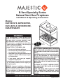
B-Vent Specialty Series
Natural Vent Gas Fireplaces
Installation & Operating Instructions
Models:
BVST/BVSTE, BVPN/BVPNE,
BVCL/BVCLE, BVCR/BVCRE,
BVBAY/BVBAYE
WARNING
IF THE INFORMATION IN THESE INSTRUCTIONS
IS NOT FOLLOWED EXACTLY, A FIRE OR EXPLOSION MAY RESULT CAUSING PROPERTY DAMAGE, PERSONAL INJURY OR LOSS OF LIFE.
—Do not store or use gasoline or other flammable vapors and liquids in the vicinity of
this or any other appliance.
—WHAT TO DO IF YOU SMELL GAS
• Do not try to light any appliance.
• Do not touch any electrical switch; do not
use any phone in your building.
• Immediately call your gas supplier from a
neighbor’s phone. Follow the gas supplier’s instructions.
• If you cannot reach your gas supplier,
call the fire department.
—Installation and service must be performed
by a qualified installer, service agency or
the gas supplier.
WARNING: Improper installation, adjustment,
alteration, services or maintenance can cause
injury or property damage. Refer to this manual. For assistance or additional information
consult a qualified installer, service agency or
the gas supplier.
DUE TO HIGH TEMPERATURES, THE APPLI
ANCE SHOULD BE
LOCATED OUT OF TRAFBVENTSPECCOVER
FIC AND AWAY FROM
FURNITURE AND DRAPERIES.
CHILDREN AND ADULTS SHOULD BE ALERTED TO THE HAZARDS OF HIGH SURFACE
TEMPERATURE AND SHOULD STAY AWAY TO
AVOID BURNS OR CLOTHING IGNITION.
YOUNG CHILDREN SHOULD BE SUPERVISED
WHEN THEY ARE IN THE SAME ROOM AS THE
APPLIANCE.
CLOTHING OR OTHER FLAMMABLE MATERIAL SHOULD NOT BE PLACED ON OR NEAR
THE APPLIANCE.
KEEP THE ROOM AREA CLEAR AND FREE
FROM COMBUSTIBLE MATERIALS, GASOLINE AND OTHER FLAMMABLE VAPORS AND
LIQUIDS.
READ BEFORE INSTALLING. SAVE THESE INSTRUCTIONS
53D9009 2/09 Rev. 4
B-Vent Specialty Gas Fireplaces
TABLE OF CONTENTS
Thank you and congratulations on your purchase of an MHSC Fireplace
Please read the Installation and Operation Instructions before using the appliance!
IMPORTANT: Read all instructions and warnings carefully before starting installation.
Failure to follow these instructions may result in a possible fire hazard and will void the warranty.
Important Safety Information............................3
Code Approval....................................................4
Fireplace Dimensions........................................5
Accessories......................................................5
Pre-Installation Information
High Elevations................................................6
Pressures and BTU’s.......................................6
Before You Install.............................................6
Fireplace Installation..........................................7
Configuration Installation.................................7
Fireplace Framing............................................8
Clearances.......................................................9
Gas Line Installation......................................10
Installation Precautions..................................12
Installation Planning.......................................12
Vent Installation................................................13
Outside Combustion Air Precautions
and Recommendations...............................16
Combustion Air Assembly..............................17
Electrical Installation.......................................18
Electrical Wiring.............................................18
Units with 6CEN Controls..............................18
Units with 6CN and 6CLP Controls................19
Log Installation.................................................20
Ember Material Placement.............................20
Log Placement ..............................................20
Lava Rock and Ember Placement.................20
Operating Instructions.....................................21
What To Do If You Smell Gas.........................21
Lighting Pilot for the First Time......................21
Units with 6CEN Controls..............................22
To Turn Off Gas..............................................22
Units with 6CN and 6CLP Controls................23
To Turn Off Gas..............................................23
Adjustment and Maintenance..........................24
Pilot Adjustment.............................................24
Flame Switch.................................................24
Units with 6CN and 6CLP Controls................24
Units with 6CEN Controls..............................24
Venturi Adjustment.........................................24
Cleaning and Maintenance............................25
Safety Checklist.............................................26
Replacement Parts...........................................27
Troubleshooting...............................................28
Warranty............................................................30
53D9009
IMPORTANT SAFETY INFORMATION
B-Vent Specialty Gas Fireplaces
INSTALLER
OWNER
Please leave these instructions with the appliance.
Please retain these instructions for future reference.
WARNING
• Read this owner’s manual carefully and completely before trying to assemble,
operate, or service this fireplace.
• Any change to this fireplace or its controls can be dangerous.
• Improper installation or use of this fireplace can cause serious injury or death
from fire, burns, explosions, electrical shock and carbon monoxide poisoning.
This fireplace is a decorative gas appliance. This fireplace must be properly installed by a qualified service
person.
4. Never install the fireplace:
CARBON MONOXIDE POISONING: Early signs of
carbon monoxide poisoning are similar to the flue with
headaches, dizziness and/or nausea. If you have these
signs, the fireplace may not have been installed properly.
Get fresh air at once! Have the fireplace inspected and
serviced by a qualified service person. Some people are
more affected by carbon monoxide than others. These
include pregnant women, people with heart or lung disease or anemia, those under the influence of alcohol,
and those at high altitudes.
mable objects are less than 42” from the front,
top or sides of the fireplace
• in high traffic areas
• in windy or drafty areas
5. This fireplace reaches high temperatures. Keep
children and adults away form hot surfaces to avoid
burns or clothing ignition. Fireplace will remain hot
for a time after shutdown. Allow surfaces to cool before touching.
6. Carefully supervise young children when they are in
the room with fireplace.
7. Do not modify fireplace under any circumstances.
Any parts removed for servicing must be replaced
prior to operating fireplace.
8. Turn fireplace off and allow to cool before servicing, installing or repairing. Only a qualified service
person should install, service or repair the fireplace.
Have burner system inspected annually by a qualified service person.
9. You must keep control compartments, burners and
circulating air passages clean. More frequent cleaning may be needed due to excessive lint and dust
form carpeting, bedding material, pet hair, etc. turn
off the gas valve and pilot light before cleaning fireplace.
10. Have venting system inspected annually by a qualified service person. If needed, have venting system
cleaned or repaired. Refer to Cleaning and Maintenance, Page 23.
11. Keep the area around your fireplace clear of combustible materials, gasoline and other flammable vapor and liquids. Do not run fireplace where these are
used or stored. Do not place items such as clothing
or decorations on or around fireplace.
12. Do not use this fireplace to cook food or burn paper
or other objects.
13. Never place anything on top of fireplace.
Propane/LP gas and natural gas are both odorless. An
odor-making agent is added to each of these gases. The
odor helps you detect a gas leak. However, the odor
added to these gases can fade. Gas may be present
even though no odor exists.
Make certain you read and understand all warnings.
Keep this manual for reference. It is your guide to safe
and proper operation of this fireplace.
1. This appliance is only for use with the type of gas
indicated on the rating plate. This appliance is not
convertible for use with other gases unless a certified kit is used.
2. For propane/LP fireplace, do not place propane/LP
supply tank(s) inside any structure. Locate propane/
LP supply tank(s) outdoors. To prevent performance
problems, do not use propane/LP fuel tank of less
than 100 lbs. capacity.
3. If you smell gas:
• shut off gas supply
• do not try to light any appliance
• do not touch any electrical switch; do not use
•
any phone in your building
immediately call your gas supplier from a neighbor’s phone. Follow the gas supplier’s instructions.
• in a recreational vehicle
• where curtains, furniture, clothing, or other flam-
Continued on Page 4
53D9009
IMPORTANT SAFETY INFORMATION
B-Vent Specialty Gas Fireplaces
Continued on Page 4
14. Do not use any solid fuels (wood, coal, paper, cardboard, etc.) in this fireplace. Use only the gas type
indicated on rating plate.
15. This appliance, when installed, must be electrically
grounded in accordance with local codes or in the
absence of local codes, with the National Electrical Code, ANSI/NFPA 70 or the Canadian Electrical
Code, CSA C22.1.
16. Do not obstruct the flow of combustion and ventilation air in any way. Provide adequate clearances
around air openings into the combustion chamber
along with adequate accessibility clearance for servicing and proper operation.
17. When the appliance is installed directly on carpeting,
tile or other combustible material other than wood
flooring, you must set appliance on a metal or wood
panel or hearth pad extending the full width and
depth of the appliance.
IMPORTANT:
PLEASE READ THE FOLLOWING CAREFULLY
It is normal for fireplaces fabricated of steel to give off
some expansion and/or contraction noises during the
start up or cool down cycle. Similar noises are found
with your furnace heat exchanger or car engine.
18. Do not use fireplace if any part has been exposed to
or has been under water. Immediately call a qualified service person to arrange for replacement of the
unit.
19. Do not operate fireplace if any log is broken.
20. Do not use a blower fireplace, heat exchanger fireplace or any other accessory not approved for use
with this fireplace.
21. The fireplace is not intended for use with a thermostat.
22. This appliance must be installed with draft hood in
same atmospheric pressure zone as the combustion
air inlet to the appliance.
23. For Massachusetts Residents Only: This product
must be installed by a licensed plumber or gas fitter
when installed within the Commonwealth of Massachusetts. Flexline installation must not exceed 36”.
IMPORTANT:
PLEASE READ THE FOLLOWING CAREFULLY
It is not unusual for gas fireplace to give off some odor
the first time it is burned. This is due to the manufacturing process.
Please ensure that your room is well ventilated
during burn off - open all windows.
WARNING
WARNING
It is recommended that you burn your fireplace for at
least en (10) hours the first time you use it.
Never connect unit to private
(non-utility) gas wells. This gas is
commonly known as wellhead gas.
Proposition 65 Warning: Fuels listed in gas, wood burning or oil fired appliances, and the products
of combustion of such fuels, contain chemicals known to the State of California to cause cancer,
birth defects and other reproductive harm.
California Health and Safety Code Sec. 25249.6
CODE APPROVAL
These appliances have been tested by OMNI-Test Laboratories, Inc. and found to comply with the established standards for VENTED GAS FIREPACES in the US and Canada as follows:
LISTED VENTED GAS FIREPLACE
TESTED TO: ANSI Z21.50a-2008 CSA2.22a-2008
53D9009
APPLIANCE SYSTEM COMPONENTS
B-Vent Specialty Gas Fireplaces
FIREPLACE DIMENSIONS
1256QE”
656M”
19”
Top View
5356”
756O”
4056M”
426”
3756M”
2256M”
756O”
1”
36”
38”
Front View
1”
2256”
2456”
Side View
8”
Figure 1
656O”
856”
8(6”
Bottom View
ACCESSORIES
539009
Configuration Kits
Accessories
dimsLP Conversion Kit
Bay Kit
6BKb-vent specialty
6CEN
Corner Kit (Left and Right) 6CK
6CN LP Conversion Kit
Island Kit
6IK
6CLP Natural Conversion Kit
Peninsula Kit
6PNK
Outside Air Kit
See-Thru Kit
6SK
Back Refractory Look Panel
Side Refractory Look Panel
Hand Held Remote Control
GVCKDV6E
GCK6CLP
GCK6CN
6AK
6BKB
6BKS
RC2
Control Kits
Control Kit Natural Gas Standing Pilot
6CN
Control Kit Propane/LP Gas Standing Pilot 6CLP
Control Kit Natural Gas Electronic Ignition 6CEN
53D9009
PRE-INSTALLATION INFORMATION
B-Vent Specialty Gas Fireplaces
HIGH ELEVATIONS
Input ratings are shown in BTU per hour and are certified without deration for elevations up to
4,500 feet (1,370 m) above sea level.
For elevations above 4,500 feet (1,370 m) in USA, installation must be in accordance with the
current ANSI Z223.1/NFPA 54 and/or local codes having jurisdiction.
In Canada, please consult provincial and/or local authorities having jurisdiciton for installation at
elevations above 4,500 feet (1,370 m).
ORIFICE SIZES, PRESSURES AND BTUs
NATURAL GAS
Manifold Press: (w.c.)
Maximum Supply Pressure
Minimum Supply Pressure
Model Number
Max. BTU/hr Input
3.5”
7”
4.5”
PROPANE GAS
Manifold Press: (w.c.)
Maximum Supply Pressure
Minimum Supply Pressure
10”
13”
11”
B-Vent Specialty
Natural Propane
42,000
42,000
BEFORE YOU START
Read this homeowner manual thoroughly and follow all instructions carefully. Inspect all contents
for shipping damage and immediately inform your dealer if any damage is found. Do not install any
unit with damaged, incomplete, or substitute parts. Check your packing list to verify that all listed
parts have been received.
ITEMS REQUIRED FOR INSTALLATION
Tools:
• Phillips screwdriver
• Hammer
• Saw and/or saber saw
• Level
• Measuring tape
• Electric drill and bits
• Pliers
• Square
• Pipe Wrench
Building Supplies:
• Framing materials
• Wall finishing materials
• Caulking material (noncombustible)
• Fireplace surround material (noncombustible)
• Piping complying with Local Codes
• Tee joint
• Pipe sealant approved for use with Propane/LP gas
(resistant to sulfur compounds)
53D9009
PRE-INSTALLATION
B-Vent Specialty Gas Fireplaces
CONFIGURATION INSTALLATION
Part 1
• Remove front glass door by removing the cardboard fillers at the top and lifting up and away from
the appliance.
• Install the handles onto the door using screws from the handle package.
• Keep front glass door off of the appliance until installation of Configuration Kit and Control Kit are
completed.
• Remove carton containing logs. Retain for later installation.
• Remove and dispose of the cardboard support for log carton.
• Remove burner pan by removing two (2) screws. Replace screws in holes for later use.
• Remove the hearth pan that burner was secured to by lifting up and off of its four (4) locating pins.
Part 2
The appliance is now ready for one of the following Configuration Kits:
Bay Kit
Corner Kit (left or right)
Island Kit
Peninsula Kit
See-thru Kit
6BK
6CK
6IK
6PNK
6SK
Complete installation instructions are included with each kit.
Part 3
After installing the Configuration Kit, the appliance is ready for one of the following Control Kits:
Control Kit Natural Gas Standing Pilot
Control Kit Propane/LP Gas Standing Pilot
Control Kit Natural Gas Electronic Ignition
6CN
6CLP
6CEN
Complete installation instructions are included with each kit.
• Once your Configuration Kit and Control Kits have been installed, install the hearth pan by positioning it down onto the four (4) locating pins. Make sure the access panel is positioned over the controls.
• The burner may now be installed onto the hearth pan. This is done by positioning the large opening
in the burner, over the pilot protruding up from the control panel. Lower the burner around the pilot
down onto the firebox bottom.
• Looking through the large opening in the burner pan, position the burner tube with the air shutter
onto the orifice mounted on the control panel.
• The burner may now be secured at both ends with screws removed earlier.
Proceed with installation.
53D9009
FRAMING INFORMATION
B-Vent Specialty Gas Fireplaces
FIREPLACE FRAMING
It is best to frame your fireplace after it is positioned and the vent system installed. Use 2 x 4’s and
frame to local building codes.
To install the fireplace facing flush with the finished wall, position the framework to accommodate the
thickness of the finished wall.
It is not necessary to install a hearth extension with this fireplace system.
WARNING
CAUTION
The junction box should be wired to the electrical system at the time of installation of the fireplace.
Wiring must be performed by a qualified person in a manner to conform with National Electrical Code
ANSI/NFPA 70 and all applicable local codes.
Always check and make sure power
is OFF before attempting to install or
service any electrical wiring or components.
Do not fill spaces around firebox with
insulation or other materials. This
could cause a fire.
6" B-Vent flue
4” O.A. Inlet
1256QE”
456O”
96M”
19”
Figure 2
2356”
Framing
Dim. for
See-thru
Top View
ialty framing
756O”
426”
3756M”
4056M”
2256M”
4256O”
Framing Min.
All Units
756O”
1"
36”
38”
3856O” Framing Min.
Peninsula & Corner
39” Framing Min.
See-thru
1"
2256”
2456”
246”
1"
1/2" Min.
Clearance
Bay & Corner
Side View
Front View
53D9009
FRAMING INFORMATION
B-Vent Specialty Gas Fireplaces
CLEARANCE TO COMBUSTIBLES
Sides........................................................... 1/2”
Back............................................................ 1/2”
Top................................................................. 0”
Front............................................................. 37”
Bottom............................................................ 0”
When the fireplace is installed directly on carpeting, vinyl tile or other combustible materials (other than
wood flooring), it shall be installed on a metal or wood panel extending the full width and depth of the
fireplace.
Provide adequate ventilation air.
Provide adequate accessibility clearance for servicing and operating the fireplace.
Never obstruct the front opening of the fireplace.
MANTEL CLEARANCES
856O”
Combustible Mantel
and Trim Allowed
Above Dotted Line
12”
256M”
9”
Measure from
Top of Opening
Figure 3
Front of Fireplace
FP2206
FP2206
mantel clearance
53D9009
GAS LINE INSTALLATION
B-Vent Specialty Gas Fireplaces
CHECK GAS TYPE
Use proper gas type for the fireplace you are installing. If you have conflicting gas types, do not
install fireplace. See dealer where you purchased the fireplace for proper fireplace for your gas
type.
INSTALLING GAS PIPING TO FIREPLACE LOCATION
•
•
•
•
•
•
External regulator (supplied by installer)
Piping (check local codes)
• Tee Joint
• Pipe wrench
Sealant (resistant to propane/LP gas)
WARNING
Before installing, make sure you have the items listed below:
A qualified installer or service person
must connect appliance to gas supply.
Follow all local codes.
CAUTION
INSTALLATION ITEMS NEEDED
For propane/LP units, never connect
fireplace directly to the propane/LP
supply. This burner system requires an
external regulator (not supplied). Install
the external regulator between the burner system and propane/LP supply.
Test gauge connection*
Sediment trap (optional but recommended)
Approved flexible gas line with gas connector (if allowed by
local codes - not provided)
*A CSA design-certified equipment shutoff valve with 1/8”
NPT tap is an acceptable alternative to test gauge connection. Purchase the CSA design-certified equipment shutoff
valve from your dealer.
External
Regulator
CAUTION
100 gal.
(min) Propane/LP
Supply
Tank
Use only new black iron or steel pipe. Internally tinned copper or copper tubing
can be used per National Fuel Code, section 2.6.3, providing gas meets hydrogen
sulfide limits, and where permitted by
local codes. Gas piping system must be
sized to provide minimum inlet pressure
(listed on data plate) at the maximum
flow rate (BTU/hr). Undue pressure loss
will occur if the pipe is too small.
WARNING
For propane/LP connections only, the installer must supply an external regulator. The external
regulator will reduce incoming gas pressure. You must reduce incoming gas pressure to between
11 and 13 inches of water. If you do not reduce incoming gas pressure, burner system regulator
damage could occur. Install external regulator with the vent pointing down as shown in Figure 4.
Pointing the vent down protects it from freezing rain or sleet.
External regulators may be necessary
for natural gas. One- or two-pound systems will damage this appliance and
may cause fire hazard.
Vent
Pointing
Down
FP1977
Figure 4 External Regulator with Vent Pointing Down
(Propane/LP Only)
&0
When using copperEXTERNALREGULATOR
or flex connectors use only fittings approved for gas connections. The
gas control inlet is 3/8” NPT.
10
53D9009
B-Vent Specialty Gas Fireplaces
CAUTION
WARNING
GAS LINE INSTALLATION
Only persons licensed to work with gas
piping may make the necessary gas
connections to this appliance.
A manual shut-off valve must be installed
upstream of the appliance. Union tee and
plugged 1/8” NPT pressure tapping point
should be installed upstream of the appliance. Figure 5
To accommodate the various configurations, access openings in the bottom of the unit are provided for
gas line and wall switch wires. This may not be convenient for some installation, if so you may drill an
access opening into the lower face of the unit (1” for gas line, 1/2” for the grommet).
NOTE: The gas line connection may be made using 1/2” rigid tubing or an approved flex connector. Since some municipalities have additional local codes, it is always best to consult your
local authorities and the current edition of the National Fuel Gas Code ANSI Z223.1/NFPA 54. In
Canada CSA-B149 (1 or 2) Installation Code.
IMPORTANT: Install main gas valve (equipment shut-off
valve) in an accessible locations. The main gas valve is for
turning on or shutting off the gas to the fireplace.
Check your building codes for any special requirements for
locating equipment shut-off valve to fireplaces.
CAUTION
A listed manual shut-off valve must be installed upstream of the appliance. Union tee and plugged 1/8”
NPT pressure tapping point should be installed upstream of
the appliance. Figure 5
Use pipe joint sealant that is resistant to
liquid petroleum (LP) gas.
Apply pipe joint sealant lightly to male threads. This will prevent excess sealant form going into pipe.
Excess sealant in pipe could result in clogged burner system valves.
We recommend that you install a sediment trap/drip leg in supply line as shown in Figure 5. Locate sediment trap/drip leg where it is within reach for cleaning. Install in piping system between fuel supply and
burner system. Locate sediment trap/drip leg where trapped matter is not likely to freeze. A sediment
trap traps moisture and contaminants. This keeps them from going into the burner system gas controls.
If sediment trap/drip leg is not installed or is installed wrong, burner system may not run properly.
Flexible Connector
Adapter Fitting
Figure 5
Shut-Off Valve
FP2205
Black Iron Pipe
&0
GASLINECONNECTION
Natural Gas
From Gas Meter
(4.5” w.c. to 7” w.c. Pressure)
Propane/LP
From External Regulator
(11” w.c. to 13” w.c. Pressure)
FP1978
53D9009
11
VENT INSTALLATION
Read all instructions completely and thoroughly before attempting installation.
Failure to do so could result in serious injury, property damage or loss of life.
Operation of improperly installed and maintained venting system could result in
serious injury, property damage or loss of life.
NOTICE
WARNING
B-Vent Specialty Gas Fireplaces
Failure to follow these instructions will void the warranty.
INSTALLATION PRECAUTIONS
Consult local building codes before beginning the installation. The installer must make sure to select
the proper vent system for installation. Before installing vent kit, the installer must read this fireplace
manual and vent kit instructions.
Only a qualified installer/service person should install venting system. The installer must follow these
safety rules:
• Wear gloves and safety glasses for protection.
• Use extreme caution when using ladders or when on rooftops.
• Be aware of electrical wiring locations in walls and ceilings.
The following actions will void the warranty on your venting system:
•
•
•
•
Installation of any damaged venting component.
Unauthorized modification of the venting system.
Installation of any component part not manufactured or approved by MHSC.
Installation other than permitted by these instructions.
INSTALLATION PLANNING
“B” VENT PIPE
See venting installation instructions provided by the B-Vent manufacturer.
NOTE: This APPLIANCE MUST BE INSTALLED using “B” vent type pipe that has been listed
by a nationally recognized testing agency.
Refer to B-Vent Pipe Sizing chart for proper elbow offset runs.
This appliance must be installed using 6” type “B” vent.
Locate chimney center line dimension form a combustible back wall. Page 9, Figures 3 and 4
• Minimum vertical chimney height - 7’
• Minimum height with two (2) 90° elbows - 6’
• Elbow requirements allow a maximum of two (2) 90° elbows or four (4) 45° elbows per
installation.
NOTE: Two (2) 45° elbows = one (1) 90° elbow
• Horizontal run must never exceed 50% of the height of the vent system.
12
53D9009
VENT INSTALLATION
B-Vent Specialty Gas Fireplaces
FIRESTOP INSTALLATION
A ceiling firestop must be installed if the vent passes through a ceiling. Refer to the instructions from
the pipe manufacturer. To position firestop refer to Figures 6 and 7. Only one (1) firestop required per
frame.
NOTE: A firestop is not required at the roof.
Locate and Install Firestop
1. For ceiling firestops, position a plumb bob over the center of the vertical pipe to spot a hole through
which the pipe will penetrate.
2. Drill a hole through this center point and check for obstructions (i.e. wiring or plumbing).
3. Reposition the fireplace and vent system, if necessary, to accommodate ceiling joists or obstructions.
4. Cut an 11” x 11” hole through the ceiling, using the center point.
5. Frame the hole with framing lumber the same size as the ceiling joists. Position firestop. If attic is
above, mount firestop on top of framing. Figure 6. If room is above, mount firestop on the bottom of
framing. Figure 7. Secure with nails or screws.
6. Run vent through firestop.
Nails
Joist
Nails
Firestop
Spacer
Joist
FP2020
Firestop Spacer
NOTICE
Figure 6 Install Firestop in Attic
Figure 7 Install Firestop in Ceiling
When installing in a chase, you should insulate the chase as you would the outside walls of your home. This is especially important in cold climates. Insulation
FP2020
should be considered a combustible
material. Maintain proper clearances to all
combustible materials.
firestop
NOTICE
10/08
Treatment of firestops and construction of the chase may vary from buiding type
to building type. These instructions are not substitutes for the requirements of
local building codes. You must follow all local building codes.
53D9009
13
VENT INSTALLATION
B-Vent Specialty Gas Fireplaces
VERTICAL TERMINATION
Major building codes specify a minimum vent height above the rooftop depending on the pitch of the
roof. Refer to Figure 8 for minimum heights, provided the termination cap is at least 8’ from a vertical
wall and 2’ below a horizontal overhang. Trees, buildings, adjoining roof lines and adverse wind conditions may require taller chimneys than what is shown.
Listed Vertical
Termination
Cap
Lowest Discharge
Opening
H Listed Gas Vent
12 X Roof Pitch is x/12
H (Min) - Minimum
Height from Roof to Lowest Discharge Opening
Roof Pitch
H Min. (ft)
Flat to 6/12
1’
6/12 to 7/12
1’3”
Over 7/12 to 8/12
1’6”
Over 8/12 to 9/12
2’
Over 9/12 to 10/12
2’6”
Over 10/12 to 11/12
3’3”
Over 11/12 to 12/12
4’
Over 12/12 to 14/12
5’
Over 14/12 to 16/12
6’
Over 16/12 to 18/12
7’
Over 18/12 to 20/12
7’6”
Over 20/12 to 21/12
8’
FP1022
NOTE: Vertical termination must be
at least 8’ from vertical wall.
Figure 8 Minimum Vent Height for Various Roof Pitches
LOCATE AND INSTALL VERTICAL TERMINATION
FP1022
NOTE: When working on the foor, cover the opening of the installed vent pipe below to prevent debris
Typical Straight Up Installation
falling in.
1/26/00 djt
1. Locate and mark the vent center point on the underside of the roof, and drive a nail trough the center
joint.
2. The size of the roof hole framing dimensions depends on the pitch of the roof.
3. Cut and frame the roof hole.
4. Continue to install vent sections through the roof hole until reaching the appropriate distance above
the roof.
5. Attach a flashing to the roof using nails, and use a non-hardening mastic around the edges of the
flashing base when it meets the roof.
6. Attach a storm collar over the flashing joint to form a watertight seal. Place non-hardening mastic
around the joint, between the storm collar and the vertical pipe.
7. Attach termination per pipe manufacturer’s instructions.
14
53D9009
VENT INSTALLATION
B-Vent Specialty Gas Fireplaces
Figure 9
Storm Collar
Figure 10
Flashing
Attach 6” “B” Vent Pipe
to Transition using Four
(4) Sheet Metal Screws
7’
Min.
6” Type “B”
Gas Vent
Minimum Clearance
as Specified by Vent
Manufacturer
Listed Ceiling
Support
Attach Transition to
Flue Collar using
Three (3) Sheet Metal
Screws
“B” Vent Clearance
as Specified by Vent
Manufacturer
1/2” Air Space to
Sides and Rear of
Fireplace
FP2208
Units Flue Collar
Wall
&0
TRANSITIONPIPE
Floor
Gas Appliance
Approved
Termination
FP2207
4’ Max
FP2207
straight up install
As Specified
6‘ Min.
by Vent Manufacturer
Support
Approved Thimble for
6” Type “B” Gas vent
Through Wall
Figure 11
6” Type “B” Gas
Vent Chimney
Wall
1/2” Air Space to Sides
and Rear of Fireplace
Gas Appliance
Floor
FP2209
53D9009
FP2009
vent w elbows
15
OUTSIDE COMBUSTION AIR PRECAUTIONS and RECOMMENDATIONS
B-Vent Specialty Gas Fireplaces
NOTE: The use of outside air for combustion is optional unless required by building codes. It is only necessary to supply
outside combustion air to one side of fireplace. Use model OAC4 combustion air kit
(refer to Page 17).
Duct Extended
to Miss Joist
1. Avoid extremely long runs and numerous turns in duct leading from fireplace
to combustion air assembly. These conditions increase the resistance to free flow
of air through duct. Figures 12 and 13
2. Locate combustion air assembly at an
exterior location. Make sure the location
cannot be accidentally blocked. Locate
assembly above snow line to prevent
snow from blocking assembly.
Installed above Basement or
Crawl Space
3. Never mount combustion air inlet assembly in garage or storage area where combustible fumes (gasoline) might be drawn
into fireplace.
FP2210
Figure 12
4. Combustion air may be drawn from crawl
space under house when adequate supply of air is provided by open ventilation.
Figure 12
NOTE: Never take combustion air from attic space or garage space.
NOTE: Install outside combustion air
ONLY ON LEFT-HAND SIDE of fireplace.
8”
Maximum
Inlet Grille
in Soffit
(Overhang)
Figure 13
Installed on Concrete Slap
16
53D9009
COMBUSTION AIR ASSEMBLY
B-Vent Specialty Gas Fireplaces
WARNING
MODEL AK4 COMBUSTION AIR ASSEMBLY
1. Remove the cover plate from the 4” outlet opening
location on the left outside of the fireplace.
WARNING
2. Place starting collar (4”) into hole on left side of
fireplace. Fasten starting collar in place with four (4)
sheet metal screws provided. Figure 14
NOTE: The air starting collar extends through the
fireplace outer wrap. When the air starting collar is
securely attached, it will form a seal against the fireplace wall.
3. Cut a 6” diameter opening for model AK4 in the
outside wall covering where the outside vent is to be
located. Figure 16
DO NOT remove the cover
if the outside air will not be
connected.
Do not use a combustible duct. Always
use UL Listed Class 0 or 1 duct material.
If necessary to splice duct, use Model
403 duct connector to splice duct sections.
Air Starting Collar
4. Select and cut a piece of duct long enough to attach
to the fireplace and stick out at least 3” beyond the
face of the wall to which the AK4 inlet air vent will
be attached. Cut duct with a standard pocket knife.
Figure 15
Screws
Duct
5. If using insulating duct, push the insulation back
from one end of the duct approximately 2”. Figure 16
Left Side of
Fireplace
AK4 Starting Collar
Screws
Left Side of
Fireplace
FP2024
Figure 15
Sheet Metal
Screws
6” Diameter
Hole
FP2023
&0
ATTACHOUTSIDEAIRDUCT
Shorter End of Air
Starting Collar
Nail
Hole
Figure 14
&0
ATTACHSTARTCOLLAR
6. Slip the exposed
end of the duct over the starting
Duct Extending 3”
Min.
collar on the fireplace.
7. Using the sheet metal screws provided, secure the
duct end to the collar attached to the fireplace.
FP2025
8. Nail or screw the combustion air assembly to the
surface of the wall.
Figure 16
AK4 Inlet Air
Vent
Screws
&0
COMBAIRASSY
53D9009
17
ELECTRICAL INSTALLATION
B-Vent Specialty Gas Fireplaces
WARNING
Electrical connections should only be performed by a qualified, licensed
electrician. Main power must be off when connecting to main electrical
power supply or performing service. All wiring shall be in compliance
with all local, city and state codes. The appliance, when installed, just be
electrically grounded in accordance with local codes, or in the absence
of local codes, with the National Electrical Code ANSI/NFPA 70 (latest edition) and Canadian Electrical Code, CSA C22.1.
CAUTION
ELECTRICAL WIRING
Label all wires before disconnecting
when servicing controls. Wiring errors
can cause improper and dangerous operation.
UNITS WITH 6CEN CONTROLS
1. Determine a convenient location within 20’ and cut a hole large enough to accommodate the
wall switch yet be covered with a wall plate. It is not necessary to use a wall box, but one may
be used.
2. Route the wire provided through the 1/2” black plastic grommet in the unit.
3. Route the wire into the wall box, connect it to the switch, mount the switch and cover.
4. Set the wall switch to “OFF”.
5. Light the pilot according to instructions.
Pilot
Gas Control
Valve
IN
Pilot Gas
Supply
ON
Gas Line Out
to Burner
Pilot Burner
Ground
OFF
Wire Type
105° C Replace
with same or
Equivalent
Inlet Pressure
Tap
Control Adjust
Screw
Electronic Control
Outlet Pressure
Tap
PV
PV
MV
MV
WARNING
Explosion hazard. Can cause
serious injury or death.
This device can malfunction if
it gets wet. Never try to use a
device that has been wet - replace it.
Figure 17
Gas Supply In
S8600H
100% SHUTOFF IP
90 SEC. L.O.
Power Supply
120V 60Hz
24V, 60 Hz
PV-1A MAX. MV-1A MAX.
Wall Switch
Ignition Wire
Limit Switch
Gas Control/Electronic Ignition Wiring
18
FP2211
6CEN wiring dia
Transformer
Gnd
53D9009
ELECTRICAL INSTALLATION
B-Vent Specialty Gas Fireplaces
UNITS WITH 6CN and 6CLP CONTROLS
The control system on this fireplace is powered by the thermocouple and operates on approximately
500m V (one-half volt). All connections in the wiring must be clean and tight. The wall switch should be
located as near the fireplace as practical. Do not locate the wall switch so that more than 25’ of wire
provided must be used. Additional wire and splices will cause a voltage drop and may cause the control
system to not operate.
1. Determine a conventional location within 20’ and cut a hole large enough to accommodate the wall
switch yet be covered with a wall plate. It is not necessary to use a wall box, but one may be used.
2. Route the wire provided through the 1/2” black plastic grommet in the unit.
3. Route the wire into the wall box, connect it to the switch, mount the switch and cover.
4. Set the wall switch to “OFF”.
5. Light the pilot according to instructions.
Limit Switch
Wall Switch
To Piezo Electrode
OFF/PILOT/ON Control Knob
Inlet Pressure Tap
To Thermocouple
Generator
Manifold Tubing
Pilot Tubing
Tp Thermocouple
SIT 820 NOVA Control
Figure 18
53D9009
FP2212
6CN CLP wiring
19
LOG INSTALLATION
B-Vent Specialty Gas Fireplaces
EMBER MATERIAL PLACEMENT
Special ember material provided may be placed between front porting and grate bars with a recommended 3/8” space free of ember material directly in front of the front burner ports for best performance
and effect. Figure 19. Blockage of the burner ports may create increased soot and carbon buildup.
3/8”
Figure 19
LG605
Porting
Typical, both sides for Peninsula
and See-thru configurations
Ember Material
Top View
(Front Log and Grate Bars)
LG605
Bvent spec ember
LOG PLACEMENT
Position logs and twigs onto burner as shown in Figure
20.
LAVA ROCK PLACEMENT
WARNING
To further enhance the hearth, lava rock may be placed
on the hearth pan area to simulate ashes. Sprinkle lava
rock on the floor of the inner combustion chamber. Evenly distribute the rock. Do not pile the lava rock up in front
of grate. Do not place lava rock on the burner.
Do not sprinkle the lava rock or ember
chunks on top of the burner. This may
cause potential sooting, glass breakage
and a fire hazard.
LG606
Figure 20
CURING INSTRUCTIONS
When lit for the first time, the fireplace may emit a slight odor for several hours. This is due to the
,'
curing and “burn in” of external parts and lubricants used in the manufacturing
process. This condition is temporary. Open doors and windows to ventilate the room(s)
sufficiently.
BVENTSPECLOGS
20
53D9009
OPERATING INSTRUCTIONS
B-Vent Specialty Gas Fireplaces
WARNING
FOR YOUR SAFETY READ BEFORE LIGHTING
If you do not follow these instructions
exactly, a fire or explosion may result
causing property damage, personal injury or loss of life.
A.This appliance is equipped with an ignition device which automatically light the pilot.
B.BEFORE OPERATING smell all around the appliance area for gas. Be sure to smell next to the floor because
some gas is heavier than air and will settle on the floor.
WHAT TO DO IF YOU SMELL GAS:
• Turn off all gas to the appliance.
• Open windows.
• Do not attempt to light any appliance.
• Do not touch any electric switch; do not use any phone in your building.
• Immediately call your gas supplier from a neighbor’s phone. Follow the gas supplier’s instructions.
• If you cannot reach your gas supplier, call the fire department.
C.Use only your hand to push in, or turn the gas control knob. Never use tools. If the knob will not push in or turn
by hand, don’t try to repair it. Call a qualified service technician. Force or attempted repair may result in a fire or
explosion.
D.Do not use this appliance if any part of it has been under water. Immediately call a qualified service technician
to inspect the appliance and to replace any pat of the control system and any gas control that has been under
water.
LIGHTING PILOT FOR THE FIRST TIME
Purge air from the supply line as follows:
• Open main shut-off valve.
• Unscrew main pressure test point.
• Leave inlet test screw open until gas comes in.
• When gas is flowing, tighten inlet screw immediately.
LEAK TESTING
WARNING
INITIAL LIGHTING
Never use an open flame to check for
gas leaks.
1. Follow the pipe from the gas supply line connection to the gas valve. Check connection for leaks with soap and
water mixture.
2. Next check for gas leaks at the burner with soap and water mixture.
3. Check the pilot for gas leaks with soap and water mixture.
53D9009
21
OPERATING INSTRUCTIONS
B-Vent Specialty Gas Fireplaces
OPERATING INSTRUCTIONS FOR UNITS WITH 6CEN CONTROLS
1.
2.
3.
4.
STOP! Read the safety information on Page 19.
Turn rocker switch to OFF.
Turn off all electric power to the appliance.
This appliance is equipped with an ignition device which automatically lights the pilot. Do
not try to light the pilot by hand.
5. Remove control access panel.
6. Turn gas control knob clockwise
to OFF.
7. Wait 5 minutes to clear out any gas. Then smell for gas, including near the floor. If you
smell gas STOP! Follow “B” - What to Do if You Smell Gas. If you do not smell gas, go to
the next step.
8. Turn gas control knob counterclockwise
to ON.
9. Replace control access panel.
10. Turn on all electric power to the appliance.
11. Turn rocker switch to “ON”.
12. If the appliance will not operate, follow the instructions To Turn Off Gas below, and call
your service technician or gas supplier.
ON
OFF
Position Indicator
FP2212
Gas Control Knob
TO TURN OFF GAS
1. Turn rocker switch or wall switch to OFF.
&0
2. Remove control access panel.
#%.CONTROLVALVE
3. Depress the control knob inward slightly and turn clockwise
to OFF.
4. Replace control access panel.
5. If the appliance is equipped with an automatic ignition device or optional blower, turn off all
electrical power to the appliance if service is to be performed.
22
53D9009
OPERATING INSTRUCTIONS
B-Vent Specialty Gas Fireplaces
OPERATING INSTRUCTIONS FOR UNITS WITH 6CN/6CLP CONTROLS
When lighting and relighting, the gas knob cannot be turned from pilot to OFF unless the knob
is depressed.
1. STOP! Read the safety information on Page 19.
2. Turn off all electric power to the appliance.
3. Turn gas control knob clockwise
to OFF.
4. Wait 5 minutes to clear out any gas. Then smell for gas, including near the floor. If you smell
gas STOP! Follow “B” - What to Do if You Smell Gas. If you do not smell gas, go to the next
step.
5. If appliance is equipped with HI-LO adjustment valve, turn counterclockwise
to
HIGH.
6. Find pilot located in front of the middle log.
7. Turn gas knob counterclockwise
to PILOT.
8. Depress and hold gas knob while lighting the pilot with the push button ignitor. Keep knob
fully depressed for one minute, then release. If pilot does not continue to burn, repeat steps
3 thru 7.
9. With pilot lit, turn gas knob counterclockwise
to ON.
10. If equipped with remote ON/OFF switch, main burner may not come on when you turn the
valve to ON or HIGH. Remote switch must be in the ON position to ignite burner.
11. Turn on all electrical power to the appliance.
Pilot
Generator
Thermocouple
FP2213
Gas Knob OFF
FP2214
Piezo Electrode
TO TURN OFF GAS
&0
1. Turn off all electrical
power to the appliance if service is to be performed.
#.#,0CONTROLS
&0
2. Push in the gas control knob slightly and turn clockwise
to OFF. Do not force.
#.,0PILOT
53D9009
23
B-Vent Specialty Gas Fireplaces
ADJUSTMENT and MAINTENANCE
Pilot Adjustment
1. Adjust the pilot screw to provide a properly sized flame.
2. Do not adjust the pilot screw all the way counterclockwise because it will leak gas.
Flame Switch
Figure 21
Units with 6CN and 6CLP Controls
1/2”
Your fireplace has been equipped with a thermocouple which senses the
flame and shuts off the gas flow to the pilot and main burner in the event
the pilot flame is unstable or becomes extinguished.
5/8”
DANGER
Do not alter wiring of the control. Replace the thermocouple only with
components approved by MHSC.
Bypassing the thermocouple may lead
to an explosion which could result in
personal injury.
FP2215
Units with 6CEN Controls
This fireplace has been equipped with a thermocouple which senses
the flame and shuts off the gas flow to the pilot and main burner in the
event the pilot flame is unstable or becomes extinguished.
Figure 22
FP2215
CN CLP pilot flame
3/8” to 1/2”
DANGER
Do not alter wiring of the control. Replace the thermocouple only with
components approved by MHSC.
Bypassing the thermocouple may lead
to an explosion which could result in
personal injury.
FP2216
Igniter - Sensor
Venturi Adjustment
Natural gas models have a closed shutter. Opening the air shutter will
cause a more blue flame, but can cause flame lifting from the burner
ports. Propane gas models have an air shutter set at 3/16” (.188 mm)
open. The same conditions as above apply for propane gas.
Figure 23
FP2216
6CEN pilot flame
NOTE
FP2217
Air shutter adjustment must only be
done by a qualified gas installer.
Closed for Natural Gas
3/16” Open for Propane/LP Gas
&0
AIRSHUTTER
24
53D9009
WARNING
CLEANING and MAINTENANCE
B-Vent Specialty Gas Fireplaces
Turn off gas before servicing fireplace. It
is recommended that a qualified service
technician perform these check-ups at
the beginning of each heating season.
Air flowing through the appliance will cause dust and lint to collect on the grate, burner and
logs. Excessive build-up of dust and lint can cause the pilot and burner to operate improperly
and produce hazardous levels of carbon monoxide, a poisonous gas. The appliance may produce carbon (soot) during operation. This carbon (soot) may collect on some logs, some areas
of the grate and on the fireplace and vent. Slight carbon build-up is acceptable.
The following is a recommended monthly maintenance program:
1. Turn the gas OFF at the line shut-off valve and allow the appliance to cool.
2. Blow or vacuum all dust and lint out of the appliance, paying particular attention to the pilot,
air shutter end of the burner, air passage into and through the appliance and control.
3. Vacuum or brush away all dust, carbon or lint on the logs and grate.
4. Turn the gas ON at the line shut-off valve and light the appliance according to the lighting
instructions.
5. Check all piping, pilot tubing and manifold connections for leaks with a soap and water or
liquid leak detecting solution. If any leaks are observed, turn the gas OFF immediately and
make the necessary repairs.
6. Light the pilot and visually inspect the flame appearance. NOTE: Any maintenance of the
appliance that requires disconnection of the appliance from the gas line or removal of the
control, burner or pilot should only be performed by a qualified person.
53D9009
25
B-Vent Specialty Gas Fireplaces
SAFETY CHECKLIST
Correct installation and safe operation of this appliance require, but are not limited to the following:
DO’S
1. Do use this appliance only on type of gas it is designed, certified and equipped.
2. Do install this appliance and all gas piping according to local codes, or in the absence of local codes,
according to the current National Fuel Gas Code, ANSI Z223.1 latest edition.
3. Do disconnect or isolate the appliance during supply line pressure testing.
4. Do locate the appliance out of traffic patterns as much as possible.
5. Do keep in mind that some furniture materials such as vinyl or plastic may deform at the temperatures
near this appliance and must be kept at greater distances.
6. Do use joint compound (pipe dope) on threaded joints of gas piping that is resistant to the action of
liquefied petroleum gas.
7. Do include a manual shutoff valve and union ahead of the controls so the controls and appliance may
be removed for servicing if necessary.
8. Do use only ground joint unions in gas piping.
9. Do include a drip leg in the gas supply connection to the appliance.
10. Do use only soap-water solution or liquid gas leak solution when checking for leaks in the gas plumbing. Never use matches, candles or other ignition sources when checking for leaks.
11. Do connect the appliance only to an agency listed vent system.
12. Do adjust the air shutter as required to produce the proper flame as described in this manual.
13. Do keep the area around the appliance clear and free from combustible materials, gasoline and other
flammable vapors and liquids.
14. Do follow the lighting and operation procedures given in this manual.
15. Do periodically inspect the pilot and burner flame as described in the maintenance section of this
manual.
16. Do clean the appliance as specified in the maintenance section of this manual.
17. Do provide electrical grounding of appliance in accordance with local codes and/or the National Electric
Code ANSI NFPA 70 latest edition.
18. Do inspect the entire venting system at least once a year and replace all parts that show evidence of
damage or deterioration.
DONT’S
1. Don’t modify or alter the appliance cabinet (jacket) in any way.
2. Don’t use this appliance on any gas other than the type for which it is equipped. The type of gas for
which the appliance was equipped at the factory is stamped on the rating plate located on the bottom
of the appliance.
3. Don’t install the appliance in areas where gasoline or any flammable liquefied or any explosive materials may be used or stored.
4. Don’t obstruct the flow of air for combustion and ventilation into or away form the appliance at any
time.
5. Don’t use this appliance if any part has been under water. Immediately call a qualified service technician to inspect the appliance and to replace any part of the control system and any gas control which
has been under water.
6. Don’t operate this appliance without proper electrical grounding according to local codes or the National Electric Code ANSI NFPA 70 latest edition.
7. Don’t operate this appliance without a proper vent.
8. Don’t connect this appliance to a chimney flue serving a solid fuel burning appliance.
9. Don’t use thermostat or automatic burner cycling devices.
26
53D9009
REPLACEMENT PARTS
B-Vent Specialty Gas Fireplaces
1
9
7
2
3
4
6
5
19
8
12
13
16
14
15
10
11
17
18
13
14
Ref. 1.
2.
3.
4.
5.
6.
7.
8.
9.
10.
11.
12.
13.
14.
15.
16.
17.
18.
19.
Description
Qty.
Twig, Top
1
Twig, End
1
Twig, Front Y
1
539009
Log, Back
B vent spec1
parts
Log, Front
1
Log, Middle
1
Front Door Assy
2
Handle Package
1
End Door Assy
2
Hearth Pan Ptd.
1
Burner Assy
1
Access Panel Ptd.
1
Hearth Pan Edge Short Ptd.
2
Hearth Pan Edge Long Ptd.
2
Radiation Shield Assy
1
Transition Section
1
Gas Control Assy EI
1
Gas Control Assy Nat.
1
Limit Switch
1
53D9009
Part No.
074270
074269
074268
074266
074265
074267
069484
037438
069485
071584
071459
071585
071567
071568
070945
070989
0776220
076673
071589
27
TROUBLESHOOTING
B-Vent Specialty Gas Fireplaces
While MHSC has made every reasonable effort to ensure this appliance operates properly and satisfactorily, sometimes problems do arise. The following troubleshooting chart lists several problems with
their probable cause and remedy. Any adjustments and/or replacements must be by a qualified person.
Do not replace any component with a different type. Use only components supplied by the manufacturer for this appliance.
Problem
Probable Cause
Remedy
Flame too large
1. Pressure regulator set too high
2. Defective regulator
3. Burner orifice too large
1. Reset, using manometer
2. Replace
3. Replace with correct size
Noisy flame
1. Too much primary air
2. Noisy pilot
3. Burr in orifice
1. Adjust air shutters
2. Reduce pilot gas
3. Remove burr or replace
Yellow or excessive flame
1.
2.
3.
4.
1.
2.
3.
4.
Floating flame
1. Blocked venting
2. Insufficient primary air
1. Clean
2. Adjust air shutter
Delayed ignition
1.
2.
3.
4.
1.
2.
3.
4.
Failure to ignite
1. Main gas off
2. Defect in gas valve
1. Open manual valve
2. Replace
1. Defective auto valve
1. Clean or replace
1.
2.
3.
4.
1.
2.
3.
4.
Burner won’t turn off
Burner won’t turn on
Too little primary air
Clogged burner ports
Misaligned orifices
Clogged vent system
Improper pilot location
Pilt flame too small
Burner ports clogged
Low pressure
Defective auto valve
Defective thermocouple
Defective switch
Defective auto pilot valve
Burner & pilot 1. Poorly functioning vent system
1.
flame go out
2. Gas supply interrupted
2.
3. Defective thermocouple or control 3.
28
Adjust air shutter
Clean ports
Realign or replace burner
Clean
Reposition pilot
Check orfice, increase gas
Clean ports
Adjust pressure regulator
Replace
Replace
Repair or replace
Replace
If pilot can be reilit but main burner & pilot go off after igntion, have vent system checked and corrected im-
mediately
Try relighting pilot and main burner. If pilot won’t relight, check thermo-
couple and control
Replace
53D9009
B-Vent Specialty Gas Fireplaces
53D9009
29
B-Vent Specialty Gas Fireplaces
30
53D9009
B-Vent Specialty Gas Fireplaces
LIMITED LIFETIME WARRANTY POLICY
LIFETIME WARRANTY
The following components are warranted for life to the original owner, subject to proof of purchase; Firebox, Combustion Chamber, Heat Exchanger, Grate and Stainless Steel Burners.
FIVE YEAR WARRANTY
The following components are warranted for five (5) years to the original owner, subject to proof of purchase; Ceramic
Fiber Logs.
BASIC WARRANTY
MHSC warrants the components and materials in your gas appliance to be free from manufacturing and material
defects for a period of two (2) years from date of installation. After installation, if any of the components manufactured
by MHSC in the appliance are found to be defective in materials or workmanship, MHSC will, at its option, replace or
repair the defective components at no charge to the original owner. MHSC will also pay for reasonable labor costs
incurred in replacing or repairing such components for a period of two (2) years from date of installation. Any products
presented for warranty repair must be accompanied by a dated proof of purchase.
This Limited Lifetime Warranty will be void if the appliance is not installed by a qualified installer in accordance with
the installation instructions. The Limited Lifetime Warranty will also be void if the appliance is not operated and maintained according to the operating instructions supplied with the appliance, and does not extend to (1) firebox/burner
assembly damage by accident, neglect, misuse, abuse, alterations, negligence of others, including the installation
thereof by unqualified installers, (2) the cost of removal, reinstallation or transportation of defective parts on the appliance, or (3) incidental or consequential damage. All service work must be performed by an authorized service representative.
This warranty is expressly in lieu of other warranties, express or implied, including the warranty of merchantability
of fitness for purpose and of all other obligations or liabilities. MHSC does not assume for it any other obligations or
liabilities in connection with sale or use of the appliance. In states that do not allow limitations on how long an implied
warranty lasts, or do not allow exclusion of indirect damage, those limitations of exclusions may not apply to you. You
may also have additional rights not covered in the Limited Lifetime Warranty.
MHSC reserves the right to investigate any and all claims against the Limited Lifetime Warranty and decide upon
method of settlement.
IF WARRANTY SERVICE IS NEEDED...
1. Contact your supplier. Make sure you have your warranty, your sales receipt and the model/serial number of your
MHSC product.
2. DO NOT ATTEMPT TO DO ANY SERVICE WORK YOURSELF.
53D9009
31
B-Vent Specialty Gas Fireplaces
MHSC
149 Cleveland Drive • Paris, Kentucky 40361
www.mhsc.com
FEBRUARY 2009
53D9009 • Rev. 4
32
53D9009