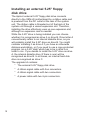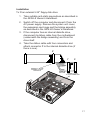
1
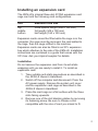
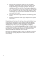
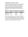
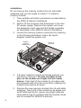
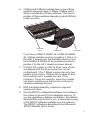
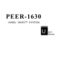
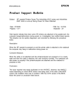
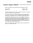
ADD-ON INSTALLATION GUIDE
XEN-LS
apricot
MITSUBISHI ELECTRIC
Intel is a registered trademark, and 80386SX, 80387SX, 80486SX and 80487SX are
trademarks, of Intel Corporation.
AT is a trademark of International Business Machines Corporation.
Information contained in this document is subject to change without notice and
does not represent a commitment on the part of Apricot Computers Limited. The
software described in this manual is furnished under a license agreement. The
software may be used or copied only in accordance with the terms of this
agreement.
It is against the law to copy any disk supplied for any other purpose than the
purchaser’s personal use.
All rights reserved; no use or disclosure without written consent.
Copyright © Apricot Computers Limited 1991
Published by
Apricot Computers Limited
3500 Parkside
Birmingham Business Park
B37 7YS
MITSUBISHI ELECTRIC
Printed in the United Kingdom
Part no. 14809731
Contents
How to use this guide 2
Installing an expansion card 3
Installing a memory module 5
Installing a coprocessor 8
Installing an external 5.25" floppy disk drive 10
1
How to use this guide
This guide contains simple, step-by-step instructions for
installing add-on options in your Apricot XEN-LS computer.
Together with the XEN-LS Owner’s Handbook, this guide
should be your only source of information when installing:
*
*
*
*
AT/ISA expansion cards
Apricot memory module
Intel 387SX or 487SX coprocessor
Apricot external 5.25" floppy disk drive
For a more general discussion of these options, and why
you might find them useful, read Chapter 2, “Using the
computer”, in the XEN-LS Owner’s Handbook.
Before you purchase and install any add-on you should be
thoroughly familiar with the installation instructions in this
guide and with the dismantling instructions provided in the
XEN-LS Owner’s Handbook. If, having read the
instructions, you are not confident about performing them
yourself, ask your Apricot supplier or an authorized Apricot
maintainer to install the option for you.
The only tools you will need are two small screwdrivers,
one flat-blade and one cross-head. Use of anti-static
equipment such as a static discharge mat and wrist strap is
also strongly advised.
Apricot continually seeks to improve its products. Because
of this, the layout of the motherboard in your XEN-LS may
differ slightly from that illustrated in this guide. For the
most up-to-date information, consult the layout
diagram which you will find inside the XEN-LS (usually
on top of the power supply unit).
2
Installing an expansion card
The XEN-LS’s internal three-slot AT/ISA expansion card
cage can hold the following card configurations:
Slot
Maximum card size
top
middle
bottom
three-quarter length (298 x 105 mm)
full length (348 x 100 mm)
half length (160 x 100 mm)
Expansion cards cannot be fitted while the cage is in the
computer; the cage must be removed, the card added to
the cage, then the cage refitted in the machine.
Expansion cards can also be fitted in an XP-i expansion
box which attaches to the side of the XEN-LS. Installation
instructions are contained in a guide that comes with the
XP-i box. Ask your Apricot supplier for details.
Installation
Do not remove the expansion card from its anti-static
wrapping until you are ready to install it. To install an
expansion card:
1. Take suitable anti-static precautions as described in
the XEN-LS Owner’s Handbook.
2. Switch off the computer and disconnect it from the
AC power supply. Remove the system unit cover
and the expansion card cage as described in the
XEN-LS Owner’s Handbook.
3. Place the card cage on a flat surface with the three
slots facing upwards.
4. Remove one of the slot blanking plates by removing
its fastening screw. Be sure to choose a slot
compatible with the size of card you intend to fit.
3
5. Remove the expansion card from its anti-static
wrapping. Take hold of the card by its edges, but
avoid touching its electrical contacts. Firmly but
carefully, push the card into the chosen expansion
slot. It will only go in one way. Keep the card upright
as you insert it so as not to place any strain on the
connectors. Do not rock the card back and forth as
you seat it in its slot.
6. Fix the card to the cage with the slot blanking plate
screw.
7. Refit the expansion card cage. Replace the system
unit cover.
Depending on the type of card you have just installed, you
may have to reconfigure your machine with the SETUP
configuration software to take advantage of the facilities
offered by the card. (If you are upgrading a diskless
workstation, the network administrator may do this for you,
or else make a copy of the SETUP software available over
the network.) The SETUP software is described in the
Reference/SETUP Diskette User’s Guide.
Keep the slot blanking plate in case you decide to remove
the card later (empty expansion slots should not be left
uncovered).
4
Installing a memory module
An Apricot XEN-LS’s system memory can be extended to a
maximum of 8 Mbytes by fitting one memory module.
Modules with a variety of capacities are available. Your
choice of module depends on how much motherboard
memory you start with, which is different for different
XEN-LS models. The following table shows the total
amount of memory attainable using the various memory
modules.
Memory modules
available
XEN-LS 386SX-16
(1 Mbyte)
XEN-LS 386SX-20
(2 Mbytes)
XEN-LS 486SX-20
(4 Mbytes)
1
2
4
6
8
2
3
5
8
4
6
8
8
5
6
8
8
Mbyte
Mbyte
Mbyte
Mbyte
Mbyte
module
module
module
module
module
Mbytes
Mbytes
Mbytes
Mbytes
Mbytes
Mbytes
Mbytes
Mbytes
Mbytes
Mbytes
Mbytes
Mbytes
If your computer already has a memory module installed,
but has not reached the maximum capacity of 8 Mbytes,
you can remove the existing memory module and replace it
with one of a higher capacity. Note that, whenever you add
a module which would raise total memory above 8 Mbytes,
the memory in excess of 8 Mbytes is unusable.
5
Installation
Do not remove the memory module from its anti-static
wrapping until you are ready to install it. To install a
memory module:
1. Take suitable anti-static precautions as described in
the XEN-LS Owner’s Handbook.
2. Switch off the computer and disconnect it from the
AC power supply. Remove the system unit cover,
the expansion card cage and the bridge assembly
as described in the XEN-LS Owner’s Handbook.
3. Locate the memory module connectors by referring
to the following illustration and/or the layout
diagram inside the system unit.
MEMORY
MODULE
CONNECTORS
FRONT OF
MACHINE
4. If a lower-capacity module is already present, you
will have to remove it. Do this carefully as the
pins on the module are fragile and are easily
broken. Take hold of the module by its edges and
pull upwards with a firm but even force, keeping the
module horizontal at all times.
5. Remove the new memory module from its anti-static
wrapping. Take hold of the module by its edges, but
avoid touching its pins. Ignore any height extender
strips which may be included with the module; these
are not needed for XEN-LS machines.
6
6. 2 Mbyte and 4 Mbyte modules have a row of three
switches along one edge (1 Mbyte, 6 Mbyte and 8
Mbyte modules do not have switches). The correct
position of these switches depends on which XEN-LS
model you have.
LOCATING
HOLE
POSITION 2
POSITION 1
If you have a XEN-LS 386SX-16 or XEN-LS 486SX20, all three switches must be in position 1 (that is, to
the right, if viewed as in the illustration above); if you
have a XEN-LS 386SX-20, the switches must be in
position 2 (to the left, if viewed as shown above).
7. Position the module so that its three rows of pins
are aligned with the three connectors on the
motherboard. (The 1 Mbyte module has only two,
parallel rows of pins. Position this module so that
the locating hole is towards the rear of the
machine.) Firmly but carefully, press the module
into place, making sure that you do not bend or
otherwise damage the pins.
8. Refit the bridge assembly, expansion cage and
system unit cover.
9. Use the SETUP configuration software to reconfigure
the system to account for the additional memory. (If
you are upgrading a diskless workstation, the network
administrator may do this for you, or else make a copy
of the SETUP software available over the network.)
The SETUP software is described in the Reference/
SETUP Diskette User’s Guide.
7
Installing a coprocessor
Apricot supply three coprocessor add-ons for XEN-LS
machines:
* Intel 80387SX-16 for the XEN-LS 386SX-16
* Intel 80387SX-20 for the XEN-LS 386SX-20
* Intel 80487SX-20 for the XEN-LS 486SX-20
Note that your XEN-LS may have already been fitted with a
coprocessor either during manufacture or by your supplier.
Installation
Do not remove the coprocessor from its anti-static wrapping
until you are ready to install it. To install a coprocessor:
1. Take suitable anti-static precautions as described in
the XEN-LS Owner’s Handbook.
2. Switch off the computer and disconnect it from the
AC power supply. Remove the system unit cover,
the expansion card cage and the bridge assembly
as described in the XEN-LS Owner’s Handbook.
3. Locate the coprocessor socket by referring to the
following illustration and/or the layout diagram inside
the system unit.
FRONT OF
MACHINE
487SX
COPROCESSOR
SOCKET
387SX
COPROCESSOR
SOCKET
(The illustration above represents a composite of
XEN-LS 386SX and 486SX machines; your
computer will have only one of the coprocessor
sockets shown.)
8
4. Remove the coprocessor from its anti-static
wrapping. Hold it only by its edges; do not touch the
pins. The coprocessor may come in a pack with
some PAL chips; these chips are not required for a
XEN-LS.
5. The coprocessor has a positioning guide in the form
of a small notch or circular recess at one corner; the
coprocessor socket has a corresponding notch (see
diagram).
487SX
387SX
Position the coprocessor as shown in the diagram,
and gently press it into the socket, making sure that
you do not bend or otherwise damage the pins.
6. Refit the bridge assembly, expansion cage and
system unit cover.
9
Installing an external 5.25" floppy
disk drive
The Apricot external 5.25" floppy disk drive connects
directly to the XEN-LS motherboard by a ribbon cable and
is powered from the DC outlet at the rear of the system
unit. The ribbon cable is threaded out of the back of the
system unit through a vacant expansion slot. Therefore,
installing the drive effectively uses up one expansion slot,
although no expansion card is needed.
While the 5.25" drive is being installed you can choose
whether it is recognised as drive A or drive B. Drive letter A
conventionally refers to an internal diskette drive, so you
will probably install the 5.25" drive as drive B. You might
consider installing it as drive A if you have an otherwise
diskless workstation, or if you need to use a copy-protected
program (on a 5.25" disk) which has to be in drive A in
order to run. If you decide to install the 5.25" drive as drive
A, the internal diskette drive (if there is one) will be
recognised as drive B. In all cases, an internal hard disk
drive is recognised as drive C.
The upgrade kit contains:
* The external 5.25" floppy disk drive.
* A ribbon signal cable with four connectors.
* A ribbon signal cable with two connectors.
* A power cable with two 4-pin connectors.
10
Installation
To fit an external 5.25" floppy disk drive:
1. Take suitable anti-static precautions as described in
the XEN-LS Owner’s Handbook.
2. Switch off the computer and disconnect it from the
AC power supply. Remove the system unit cover,
the expansion card cage and the bridge assembly
as described in the XEN-LS Owner’s Handbook.
3. If the computer has an internal diskette drive,
disconnect its ribbon cable from the motherboard
(underneath the bridge assembly) and from the
drive itself.
4. Take the ribbon cable with four connectors and
attach connector Z to the internal diskette drive (if
there is one).
Z
Y
CONNECT Z TO THE
INTERNAL FLOPPY
DISK DRIVE
FRONT OF
MACHINE
X
CONNECT X OR Y
TO THIS CONNECTOR
11
5. Plug either connector X or Y into the motherboard
as shown in the diagram opposite. Use connector X
if the 5.25" drive is to be drive A; use connector Y if
you want it to be drive B.
6. Refit the bridge assembly.
7. Remove a blanking plate belonging to a vacant slot
in the expansion card cage. If possible, use the
bottom slot.
8. Refit the expansion card cage, threading the end of
the ribbon cable out through the hole created by
removing the slot blanking plate.
9. Replace the system unit cover.
10. Using the second ribbon signal cable supplied in the
kit, connect the 5.25" drive to the end of the cable
which you have routed out through the card cage.
11. Using the power cable supplied in the kit, connect
the 5.25" drive to the DC outlet on the rear of the
system unit. (If you have an XP-i expansion box, the
DC outlet is needed to power the box. In this case,
use the auxiliary DC outlet provided in the side of
the XP-i box.)
12. Use the SETUP configuration software to declare
the presence of the new drive. (If you are upgrading
a diskless workstation, the network administrator
may do this for you, or else make a copy of the
SETUP software available over the network.) The
SETUP software is described in the Reference/
SETUP Diskette User’s Guide.
12
apricot
APRICOT COMPUTERS LIMITED
3500 PARKSIDE
BIRMINGHAM BUSINESS PARK
BIRMINGHAM B37 7YS.
MITSUBISHI ELECTRIC
Part No 14809731
Revision 01