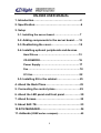
1
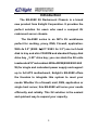
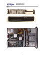
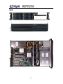
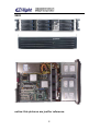
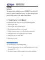
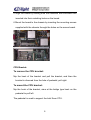
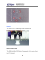
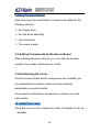
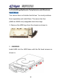
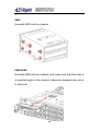
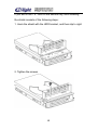
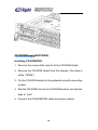
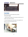
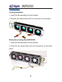
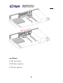
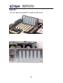
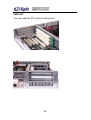
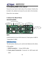
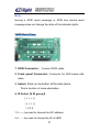
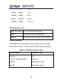
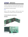
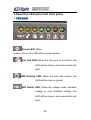
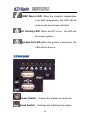
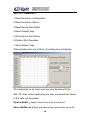
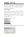
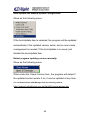
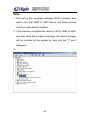
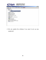
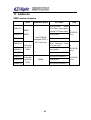
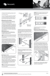
EN-898X USER MANUAL 1. Introduction…………………………………………….2 2. Specification………………..…………………………..6 3. Setup 3-1. Installing the server board………………………….7 3-2. Adding components to the server board……12 3-3. Reattaching the cover…………………………..12 3-4. Installing optional peripherals and devices Hard Drives………………………………………….13 CD-ROM/FDD………………………………………..16 Power Supply………………………………………..17 Fan……………………………………………………..18 PCI Slot……………………………………………………22 3-5. Installing 2U in the cabinet……………………..25 4. About the Back Plane………………………………...25 5. Connecting the control plane……………………….29 6. About the LED panel and front panel………………30 7. About Screws…………………………………………..32 9. About SAF-TE…………………………………………..33 10.SCSI MANAGER……………………………………….34 11. Addenda (898X series compare)………………………45 1 Introduction The EN-898X 2U Rackmount Chassis is a brand new product from Enlight Corporation. It provides the perfect solution for users who need a compact 2U rackmount server chassis. The En-898X series is an ISP’s 2U workhouse perfect for caching, proxy, DNS, Firewall, application. With 4x 3.5'' (8982: 6×3.5''/ 8983: 9x 3.5'') one inch hard disk in tray and slim CD-ROM and standard floppy disk drive bay,5.25'' drive bay; you can stack the 2U units inastandard19''rackcabinet.Witha300W(8982/8983:460 W) for single and redundant power supply and support up to full ATX motherboard, Enlight’s EN-898X offers the freedom to integrate this system to meet your needs. Whether it’s a firewall, mail, DNS, application or single host server, this EN-898X will serve your needs efficiently and reliably. This 2U solution is the easiest and quickest way to expand your capacity. 2 8981 3 8982 4 8983 notice: this pictures are just for reference. 5 Specifications EN-898X Rackmount Chassis Specifications Mainboard for factor follow SSI & ATX 12” x 13” specification Power Supply follow SSI (provide 480W Single Power Supply) LED Indicators Front Bezel: Voltage alarm(Voltage =5V, Beep Alarm Blinking 4.57 - 5.51/ Voltage =12V, Beep Alarm LED LED Blinking 11.25-12.7) FAN fail(Below 2800 rpm Beep Alarm LED Blinking), Temperature alarm(Over 60℃ and return to 55℃ Beep Alarm LED Blinking) HDD activity, Power, NIC activity, System error Pre HDD Tray: Active & HDD status x 1 (twin color LED) Cooling Fans 8981:4 x internal 80 x 80 x 25mm cooling fans 8982/8983: 4 x internal 80 x 80 x 38mm Easy-swap cooling fans /3 x rear 40 x40 x 20mm cooling fans Back Plane 8982:1(2 8983) SCSI Back plane support Ultra 320 Support up to 15,000 RPM SCSI hard disk Support 1” SCA-2 HDD with ID setting Drive Bays Hard Disk Trays IDE: 8981:4x 1” IDE drive bays 8982: 6 x 1” SCSI drive bays 8983: 9 x 1” SCSI drive bays FDD 8981/8982:1 standard FDD bay CD-ROM 8981/8982:1 slim CD-ROM bay and 5.25” drive bay PCI Slot 898X C01 3 x standard PCI adapter slots 898X D01 898X E01 6× Low-profile PCI adapter slots 2x standard PCI adapter slots Switch 1 Power switch 1 Reset switch 1 ACPI switch 1 NMI switch USB1 USB2 Annunciator FAN fail, Volt Alarm, TEMP Alarm Dimensions Weight (W x H x D) 430 x86.7x 674.2mm 8981:10.5 kg (chassis only) 8982/8983: 12.5 kg (chassis only) 6 Setup WARNING The power button on the front panel DOES NOT turn off the AC power. To remove power from server, you must unplug the AC power cord(s) from the wall outlet or the chassis. 3.1 Installing the Server Board Installing the server board consists of the following steps: 1. Removing the cover. 2. Removing the riser card &Fan &pole 3. Mounting the server board in the chassis. 4. Cabling the server board to the other chassis components. 5. Adding processors and memory to the server board. 6. Adding the riser card &Fan &pole 8. Replacing the cover. Removing the Cover To remove the top cover of the system: 1. Press the keystroke and pull the cover back and remove it from the chassis.(PIC 3.1) 2. Set chassis cover aside and away from immediate work area. 7 PIC 3.1 Mounting the Server Board With the cover off, you can now mount the server board in the chassis. Before you begin, make sure you have the server board and other associated components (processors, memory, and mounting hardware) available. To mount the server board: 1 Fix the motherboard’s screws. And save the screws. 2 Fix the I/O shields. To position the shield correctly, the outline of the connectors on the I/O shield should be view able from the chassis opening. 3 Insert connector edge of the server board into the chassis first making sure the connectors are properly seated in the I/O shield. 4 Lie board flat on the standoffs that are located on the chassis floor. 8 5 Align the board by making sure the standoffs with shoulders are inserted into their matching holes on the board. 6 Mount the board to the chassis by inserting the mounting screws supplied with the chassis through the holes on the server board. CPU Bracket: To remove the CPU bracket: Nip the hook of the bracket and pull the bracket, and then the bracket is divorced from the hole of pedestal, pull right. To mount the CPU bracket: Nip the hook of the bracket, aims at the bridge type hook on the pedestal to pull left. The pedestal is used to support the Intel Xeon CPU. 9 Notice The white screw is used to support the motherboard. M/B Insulation PAD: The M/B Insulation PAD above the pedestal will be used without the CPU bracket. 10 as follows: aim at the holes holes Affix the tape to the pedestal. 11 Cabling the Server Board After mounting the server board, it needs to be cabled to the following chassis the Floppy drive the disk drive assembly The front panel The power supply 3.2 Adding Components to the Server Board After installing the server board, you must add the desired number of processor sand memory cards. 3.3 Reattaching the Cover Once the server board and its components are installed, you are assembling the system unless you have optional peripherals you wish to install. If you need to install these components, continue on to the next section. To reattach the cover: Place the cover on the chassis and slide it forwards as far as possible. 12 3.4 Installing Optional Peripherals and Devices Hard Drives Your server does not include hard drives. You must purchase them separately and install them. The server has four (8982:six /8983:nine) swappable hard drive bays. 1. Remove the HDD trays from the chassis as shown in. 2. 8982/8983: Install HDD into the HDD frame with the flat head screws as shown in. 13 3. 8981: Reinstall HDD into the chassis 8982/8983: Reinstall HDD into the chassis, and make sure that the lever is at parallel angle to the chassis, otherwise damage may occur to the lever. 14 If you will fix the 1.6’' HDD at the second tray, then installing the shield consists of the following steps: 1. Hook the shield with the HDD bracket, and then slip to right. 2. Tighten the screws 15 CD-ROM/Floppy(8981/8982) Installing CD-ROM/FDD: 1. Remove the screws that used to fix the CD-ROM shield. 2. Remove the CD-ROM shield from the chassis. (the slide is at the “OPEN”) 3. Fix the CD-ROM bracket to the pedestal using the mounting screws. 4. Slip the CD-ROM drive to the CD-ROM bracket, and slip the slide to “lock” 5. Connect the CD-ROM/FDD cable and power cables. 16 Power Supply Boxed dimension is 330.2x106x82.2mm (W*D*H) To fix power supply: 1. Slide the power supply into the chassis and make sure it is seated in the chassis connector. 2. Connect the power cord to the power cord receptacle and plug the cord back into its power source. The single power: 17 Cooling Fans Cooling fans(8981) 1. Insert the fan assembly into the chassis. 2. Plug the fan cables back into the connectors on the power. Back plane cooling fans(8982/8983) 1. Insert the fan assembly into the chassis. 2. Plug the fan cables back into the connectors on the back plane. 18 Rear side cooling fans(8982/8983) Installing the Cooling fans consists of the following steps: 1.Fix the I/O shields. 2.Nip the left hook to the pedestal 3.Fix the right button to the pedestal 4. Fix the three fans into the back of the chassis in turn.(from right to left) 19 as follows: L1/R1: the left fan L2/R2: the second fan L3/R3: the right fan 20 Notes: If installing the Enlight’s I/O shield, make sure that the three hooks is at 80 angle to the chassis, then fix the three fans. 21 PCI Slot 898X C01 You can add three PCI cards to this server. Installing PCI SCSI add-in card: Insert the riser card to the PCI slot. Insert the daughter board to the PCI slot. And the PCI slot of daughter board MUST same with the PCI slot of riser card. 22 898X D01 You can add Low-profile PCI cards to this server. 23 898X E01 You can add two PCI cards to this server. 24 3.5 Installing 898X in the cabinet Screw the inner rails to both sides of the chassis. Position the bracket in the cabinet and screw the outer rails to the brackets. Place 2U in the cabinet. 5. About the Back Plane 8982/8983(6HDD) Front panel Connector Stop Button Jump (S1) Power Connector SCSI Connector 8983 9 HDD divided into two SCSI channels (1 back-plane 6 HDD & 1 back-plane 3 HDD) 6HDD Back Plane The back plane allows you to control and determine the status of the system. 1. SCSI Connector: Connect SCSI cable. 2. Front panel Connector: Connector for LED board with cable. 25 3. ID Select(2 ID group) S1 off 0-5 S1 on 8-13 4. The Back Plane LED SAF-TE control the red LED will be blinking HDD the green LED will be blinking Power Both red and green LED will be blinking Visual Indicators The GEM318 controls status indicator lights for up to eight device slots. Table 3-13 describes the states that are displayed. Table 3-13.Visual Indicator State Device Status Indicator Light No Error Off Faulty or rebuild stopped Steady on Rebuild Slow blink(~1/sec) Identify Fast blink(~3/sec) The identify LED can be flashed with or without a drive inserted in the slot. Consequently, the identify LED indicates which slot is housing the faulty device and shows the user in which slot a replacement drive should be installed. 26 Note: Issuing a SCSI reset message or SCSI bus device reset message does not change the state of the indicator lights. 3HDD Back Plane 1. SCSI Connector: Connect SCSI cable. 2. Front panel Connector: Connector for LED board with cable. 3. Switch: there is one button at the back plane. This is function of noise elimination 4. ID Select(4 ID group) | + + + +| | + + + +| 1234 1,2 —— be used to choose the I2C address 3,4 ——be used to choose the ID of HDD 27 3 OPEN 4 ID OPEN 0,1,2 SHORT OPEN 3,4,5 OPEN SHORT SHORT OPEN 8,9,10 11,12,13 The Back Plane Led SAF-TE control the red LED will be blinking HDD the green LED will be blinking Power Both red and green LED will be blinking Visual Indicators The GEM318 controls status indicator lights for up to eight device slots. Table 3-13 describes the states that are displayed. Table 3-13.Visual Indicator State Device Status Indicator Light No Error Off Faulty or rebuild stopped Steady on Rebuild Slow blink(~1/sec) Identify Fast blink(~3/sec) 28 The identify LED can be flashed with or without a drive inserted in the slot. Consequently, the identify LED indicates which slot is housing the faulty device and shows the user in which slot a replacement drive should be installed. Note: Issuing a SCSI reset message or SCSI bus device reset message does not change the state of the indicator lights. 5. Connecting the control plane 8982/8983 8983 29 7.About the LED panel and front panel 1. LED panel Power LED: When system turn on, the LED will be access.(green) Fan Fail LED: When the Fan error or not active, the LED will be show in and annunciator will start. HDD Activity LED: When the hard disk access, the LED will be show in.(green) Volt Alarm LED: When the voltage under standard voltage or over standard voltage, the LED will be show in and annunciator will start. 30 TEMP Alarm LED: When the chassis’s temperature over Safe temperature, the LED will be show in and annunciator will start. NIC Activity LED: When the NIC is run,the LED will be access.(green) System Fail LED:When the system is abnormity,the LED will be show in. 2. Front panel Power Switch: Powers the system up and down Reset Switch: Reboots and initializes the system 31 NMI Switch: Puts server in a halt state for diagnostic purposes. The button is recessed and allows you to issue a nonmaskable interrupt. After issuing the interrupt, a memory dump can be performed to determine the cause of the problem ACPI Switch: Advanced power management 8.About Screws A: Four of them are to fix the power Two of them are to fix the shield B: Two of them are to fix the power C: Ten of them are to fix the MB D: Three of them are to fix the slim CD-ROM E: Four of them are to fix the CD-ROM Four of them are to fix the Floppy 32 9. About SAF-TE(8982/8983) SAF-TE is proposed and standardized by Conner and Intel. It can work properly under standard SCSI adaptor and RAID controller without other concerns. Under SAF-TE standard, it is included by SCSI bus and allocated a SCSI ID, it uses a SCSI chip and 8 bits of SCSI channel. Thus the spending can be minimized. Our company's EN8982 supports part of SAT-TE commands. The objective of the SAF-TE Interface is to provide a standard, non-proprietary way for third party disk and RAID controllers to be automatically integrated with peripheral packaging that supports status signals (LEDs, audible alarm, LCD, etc.), hot swapping of hard drives, and monitoring of enclosure components. We have application software that can show HDD’s status, if SCSI SEF-TE chipset detects any fault and status (like HDD be drawn, low voltage, re- plug HDD). They will be displayed on screen or the alarm will go off. 33 10.SCSI MANAGER(8982/8983) Usage of SCSI Manager For the first time the SCSI Manager is being used, it will require a serial number to be entered: then it will ask the user to set his own password(Fig: 13): Thereafter it will require the user to enter the password every time he uses it. The next displayed main window: 34 the left panel is the browsing area for settings the right panel displays the information of the related topics When click on any of the options on the left panel, the information of the related topic will be displayed on the right panel, the settings with the red tick mean that they are products of Enlightcorp. Click on the Operation menu, a drop down menu will be displayed: Modify Password:Modify user password Expert mode:Enter professional display setting, the default setting is Common user mode Under Expert mode, all the information will be displayed in binary or hexadecimal format, 35 Users can modify every digit that was written onto the files that contain the settings, under the Common user mode, some general information would be displayed. Common user mode: Enter into the common user mode Temperature Alarm Config: Temperature Alarm Configuration Disable speaker beeping: Speaker Beeping Forbidden Server Address: Program Updating Server Address Auto Update: Auto-updating Operation Guide: Using the examples of operations under the Common user mode, some information displaying on the screen will be briefly described: When click on the main machine, there will be some system information about the machine: Number of processors Processor type OS version User name System directory Windows directory The next level under the main machine will display the setting of one of the interface controlling cards (IDE, SCSI), for 36 example: IDE port 0, AIC78U21, etc. When click on their right panel, the interface control card’s processing. Ability parameter will be displayed: Maximum Physical Pages Maximum Transfer Length Supported Asynchronous Events Alignment Mask Tagged Queuing Adapter Scans Down Adapter Used PIO When clicked on the specific settings under every controlling card, the right panel will display: Vendor ID Product ID Firmware Revision Level SCSI Path ID SCSI Target ID SCSI LUN ID Claimed:Has the program been recognized by the system with driver installed? If it is a product of Enlightcorp and supports the SAF-TE (EN8982) functions, then it will display the following 4-function 37 status: Enclosure Configuration Enclosure Status Device Status Global Status When click on the Enclosure Configuration, the right panel will display some information regarding the EN8721: Number of Device Slots Door Lock Installed Number of Temperature Sensor Audible Alarm Installed Celsius When click on the Enclosure Status, the right panel will display some information Device Slot n SCSI ID Door Lock Status Speaker Status Temperature Sensor n When click on the Device Slot Status, the right panel will display some information Slot n Device Faulty Status Slot n Device Inserted Status 38 When click on the Global Flags, the right panel will display some information Audible Alarm Control Flag Global Failure Indication Global Warning Indication Enclosure Power Status Power Failure Status Drive Failure Status Drive Warning Status When under the Expert mode, users can see all the information returned from the hard drive, click on the settings under one of the control cards, the right panel will display the standard SCSI command and SAF-TE command. SCSI COMMAND: 1.Inquiry 2.Read Buffer 3.Write Buffer 4.Test Unit Ready 5.Request Sense 6. Send Diagnostic 39 SAF-TE COMMAND: 1.Read Enclosure Configuration 2.Read Enclosure Status 3.Read Device Slot Status 4.Read Global Flags 5.Write Device Slot Status 6.Perform Slot Operation 7.Send Global Flags When double click one of them, the dialog box will display. This dialog box is for users who are very familiar with the SAF-TE rules, when performing the write command the values in the cells can be edited. Open a Buffer:Import values from a file into the cell Save a Buffer as:Save the value of the current form into a file 40 Send Command:Send the current command, when writing the command, please assign the contents in the buffer zone and byte, but command code is not included in the buffer zone. Quit:Retreat from dialog box Program Updating: While the program is running, it will detect if there is the updated version can be used at any moment. If so, the program will be updated automatically. The program will be updated automatically every day, and can be updated manually at any time. The operating process is as follow: Set new server address: Selection Menu Operation Server Address…(show as updating fig 1), then a dialogue frame will pop. 41 Auto-update and Manual-update Configuration: Show as the following menu: If the AutoUpdate item is selected, the program will be updated automatically if the updated version exists, and no man-made management is needed. If the AutoUpdate is no need, just disable the AutoUpdate item. Detect program updating version manually: Show as the following menu: When clicks the Check Version item, the program will detect if the updated version exists, if so, it can be updated at any time. You can download the SCSI Manager from the following website: http://support.enlightcorp.com.tw/ftp/Utility/scsimanager.zip 42 Note 1. First set up this compress package (SCSI manager), then load in the 8721,8982 or 8983 device and those devices could be automatically installed. 2. If the machine is installed the device of 8721, 8982 or 8983, and then setup this compress package, the device manager will be installed by the system by hand and the "?" won’t disappear. 3. 43 4. We can update the software if we need to set up new equipment. 44 11. Addenda 898X series compare HDD 8981C01 8981D01 8982D01 PCI Slot HDD 1slimCD-ROM, 1standard FDD, 1 5.25” drive bay 6Hot-Sw ap SCSI HDD 2PCI (same as 8981C01) 3PCI(Provide64bits PCI Riser card/option 32bits PCI Riser card) Low-profile 8982E01 2PCI(same as 8982C01) 8983C01 3PCI(same as 8982C01) 8983D01 8983E01 9Hot-Sw ap SCSI HDD Fan 3PCI(Provide 32bits PCI Riser card /option 64 bits PCI Riser card) 4 80*80*25 mm Low-profile 4IDE 8981E01 8982C01 External drive Low-profile NONE 2PCI(same as 8982C01) 45 4 80*80*38 mm 3 40*40*20 mm