1
Service humidification
Isothermal and adiabatic humidifiers
User manual
Integrated Control Solutions & Energy Savings
ENG
of data and information, costs of replacement goods or services, damage to
things or people, downtime or any direct, indirect, incidental, actual, punitive,
exemplary, special or consequential damage of any kind whatsoever, whether
contractual, extra-contractual or due to negligence, or any other liabilities
deriving from the installation, use or impossibility to use the product, even if
CAREL S.p.A. or its subsidiaries are warned of the possibility of such damage.
WARNINGS
CAREL S.p.A. humidifiers are advanced products, whose operation is specified
in the technical documentation supplied with the product or can be
downloaded, even prior to purchase, from the website www .carel .com. Each
CAREL S.p.A. product, in relation to its advanced level of technology, requires
setup/configuration/programming/commissioning to be able to operate in
the best possible way for the specific application. The failure to complete such
operations, which are required/indicated in the user manual, may cause the
final product to malfunction; CAREL S.p.A. accepts no liability in such cases.
The customer (manufacturer, developer or installer of the final equipment)
accepts all liability and risk relating to the configuration of the product in
order to reach the expected results in relation to the specific final installation
and/or equipment. CAREL S.p.A. may, based on prior agreements, act as a
consultant for the installation/commissioning/use of the unit, however in no
case does it accept liability for the correct operation of the humidifier and the
final installation if the warnings or suggestions provided in this manual or in
other product technical documents are not heeded. In addition to observing
the above warnings and suggestions, the following warnings must be heeded
for the correct use of the product:
DISPOSAL
The humidifier is made up of metal parts and plastic parts. In reference to
European Union directive 2002/96/EC issued on 27 January 2003 and the
related national legislation, please note that:
1. WEEE cannot be disposed of as municipal waste and such waste must be
collected and disposed of separately;
2. the public or private waste collection systems defined by local legislation
must be used. In addition, the equipment can be returned to the distributor
at the end of its working life when buying new equipment;
3. the equipment may contain hazardous substances: the improper use or
incorrect disposal of such may have negative effects on human health and
on the environment;
4. the symbol (crossed-out wheeled bin) shown on the product or on the
packaging and on the instruction sheet indicates that the equipment has
been introduced onto the market after 13 August 2005 and that it must
be disposed of separately;
5. in the event of illegal disposal of electrical and electronic waste, the
penalties are specified by local waste disposal legislation.
•
DANGER OF ELECTRIC SHOCK
The humidifier contains live electrical components. Disconnect the mains
power supply before accessing inside parts or during maintenance and
installation.
• DANGER OF WATER LEAKS
The humidifier automatically and constantly fills/drains certain quantities of
water. Malfunctions in the connections or in the humidifier may cause leaks.
Warranty on materials: 2 years (from the date of production, excluding
consumables).
Important:
Approval: the quality and safety of CAREL S.P.A. products are guaranteed by
•
•
•
•
•
•
•
•
•
•
•
•
The installation of the product must include an earth connection, using the
special yellow-green terminal available in the humidifier.
The environmental and power supply conditions must conform to the
values specified on the product rating labels.
The product is designed exclusively to humidify rooms either directly or
through distribution systems (ducts, atomising racks).
Only qualified personnel who are aware of the necessary precautions and
able to perform the required operations correctly may install, operate or
carry out technical service on the product.
For the production of atomised water, only use water with the characteristics
specified in this manual. Important, demineralised drinking water must be
used (as specified in the manual). In addition, the particles of water that are
not absorbed by the air must be removed using the droplet collection tank
(in the humidification section) and the droplet separator (at the end of the
humidification section).
All operations on the product must be carried out according to the
instructions provided in this manual and on the labels applied to the
product. Any uses or modifications that are not authorised by the
manufacturer are considered improper. CAREL S.p.A. declines all liability for
any such unauthorised use.
Do not attempt to open the humidifier in ways other than those specified
in the manual.
Observe the standards in force in the place where the humidifier is
installed.
Keep the humidifier out of the reach of children and animals.
Do not install and use the product near objects that may be damaged when
in contact with water (or condensate). CAREL S.p.A. declines all liability for
direct or indirect damage following water leaks from the humidifier.
Do not use corrosive chemicals, solvents or aggressive detergents to clean
the inside and outside parts of the humidifier, unless specifically indicated
in the user manual.
Do not drop, hit or shake the humidifier, as the inside parts and the linings
may be irreparably damaged.
the ISO 9001 certified design and production system, as well as by the
mark..
CAREL S.p.A. adopts a policy of continual development. Consequently, CAREL
reserves the right to make changes and improvements to any product
described in this document without prior warning. The technical specifications
shown in the manual may be changed without prior warning.
The liability of CAREL S.p.A. in relation to its products is specified in the
CAREL S.p.A. general contract conditions, available on the website www .
carel .com and/or by specific agreements with customers; specifically to the
extent where allowed by applicable legislation, in no case will CAREL S.p.A.,
its employees or subsidiaries be liable for any lost earnings or sales, losses
3
“Service humidification” +030220486 - rel. 1.0 - 01.09.2008
ENG
“Service humidification” +030220486 - rel. 1.0 - 01.09.2008
4
ENG
General content
COMPACTSTEAM
9
HUMISTEAM BASIC
15
HUMISTEAM WELLNESS
25
HUMISTEAM X-PLUS
35
HEATERSTEAM
47
GASTEAM
63
HUMIFOG
79
MC MULTIZONE
101
HUMIDISK
109
5
“Service humidification” +030220486 - rel. 1.0 - 01.09.2008
ENG
“Service humidification” +030220486 - rel. 1.0 - 01.09.2008
6
ENG
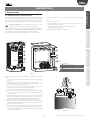
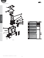
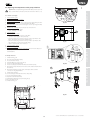
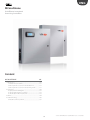
compactSteam
Umidificatore a vapore per ambienti residenziali
Residential Steam Humidifier
Contents
COMPACTSTEAM
9
1. Maintenance .............................................................................................................9
1.1 Periodical checks ....................................................................................................9
1.2 Cylinder maintenance .......................................................................................9
2. Spare parts ..............................................................................................................10
3. Alarms ........................................................................................................................11
4. Troubleshouting ..................................................................................................12
7
“Service humidification” +030220486 - rel. 1.0 - 01.09.2008
ENG
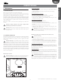
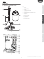
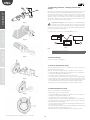
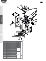
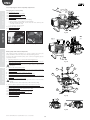
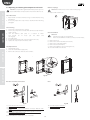
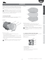
To replace the cylinder:
• Completely drain the cylinder, holding the “drain” button until the
cylinder is empty;
• Turn the humidifier off and disconnect the mains power supply;
• Remove the cover;
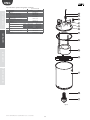
1. Maintenance
1.1 Periodical checks
After one hour of operation: check for any water leaks.
Every fortnight or after no more than 300 operating hours: check for any
water leaks and check the general operation of the cylinder. Check that
during operation no sparks form between the electrodes.
Every three months or after no more than 1000 operating hours: check
operation, check for any water leaks and, if necessary, replace the cylinder.
Check for any blackened parts of the cylinder. If there are blackened parts
in the cylinder, check the condition of the electrodes and, if necessary,
replace the cylinder.
Every year or after no more than 2500 operating hours: replace the
cylinder.
Version with injection in the duct:
• Remove the steam hose from the cylinder;
• Lift up the cylinder support bracket and lift it out of the unit;
• Disconnect the wiring from the top of the cylinder;
• Install the new cylinder in the humidifier, performing the same
operations in the reverse order.
maintenance
COMPACTSTEAM
the unit;
Important: always disconnect the power supply before
performing any maintenance operations
• Disconnect the wiring from the top of the cylinder;
• Install the new cylinder in the humidifier, performing the same
operations in the reverse order.
Important: Always disconnect the power supply before touching
the cylinder in the event of water leaks, as the water may be
carrying current.
Warning: the threaded nuts that fasten the electrical cables to the
cylinder must be tightened to 2.5/3.3 Nm (22/29 pounds per sq.
inch) to avoid the risk of fires.
spare parts
Version with room distribution:
• Unscrew the 2 bolts on the built-in fan;
• Lift up the cylinder support bracket to release it;
• Disconnect the blower from the cylinder and lift the cylinder out of
• The power supply must be always disconnected when performing
maintenance on the humidifier.
• Do not use detergents or solvents to clean the plastic components;
• Lime scale can be removed using a solution of vinegar or diluted acetic
Important warning: The humidifier and the cylinder contain live
electrical components and very hot surfaces. All service and/or
maintenance operations must be carried out by expert and
qualified personnel who are aware of the necessary precautions. Before
performing any operations on the cylinder, make sure that the humidifier
is disconnected from the power supply. Remove the cylinder from the
humidifier only after having drained it completely using the “manual
drain” procedure described in paragraph 5.3. Check that the model and
the power supply voltage of the new cylinder correspond to the data
shown on the rating plate.
acid and a soft brush; rinse the cylinder completely with fresh water.
Cleaning the fill and drain valves:
Clean the tank from any mineral deposits and check that the water can
flow freely from the tank to the drain through the drain valve. Cleaning
the supply, fill and overflow hoses: make sure these are clean and not
blocked and replace if necessary.
Cleaning the fill tank:
Clean the tank from any mineral deposits and check that the water can
flow freely from the tank to the drain through the drain valve. Cleaning
the supply, fill and overflow hoses: make sure these are clean and not
blocked and replace if necessary.
Replacing the cylinder
Important warning: After having replaced or checked the water
circuit, make sure the components have been connected correctly
and the right gaskets have been fitted. Restart the humidifier and
run a number of cleaning cycles (between 2 and 4, see paragraph 4.4
“Starting with a new cylinder”), then make sure there are no water leaks.
Important warning: The cylinder may reach high temperatures.
Let it cool down before touching it or wear protective gloves.
Fig. 1.a
9
“Service humidification” +030220486 - rel. 1.0 - 01.09.2008
troubleshouting
Important warning:
The life of the cylinder depends on several factors, including: the quantity
and type of minerals present in the water, the correct operation and
sizing of the humidifier, the capacity, as well as regular and careful
maintenance.
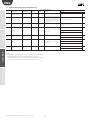
alarm table
Maintenance of the other components in the water circuit
1.2 Cylinder maintenance
ENG
maintenance
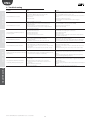
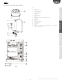
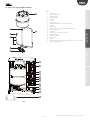
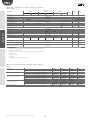
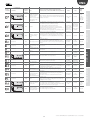
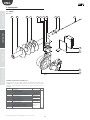
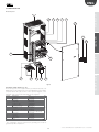
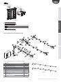
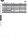
2. Spare parts
Item
5
1
2
2
2
2
2
3
4
4
5
6
7
7
8
8
9
10
11
11
12
13
13
14
12
12
4
6
2
1
11
3
13
8
7
14
9
Description
SEE TABLE 7.b
CONTROL MODULE 5.4 kg/h 230V
CONTROL MODULE 3.2 kg/h 230V
CONTROL MODULE 1.6 kg/h 230V
CONTROL MODULE 2.5 kg/h 110V
CONTROL MODULE 1.6 kg/h 110V
ON-OFF SWITCH FOR COMPACTSTEAM
FAN KIT 110V
FAN KIT 230V
FAN FILTER
STEAM DISTRIBUTOR KIT
FILL SOLENOID VALVE + DRAIN TEMPERING 110 V
FILL SOLENOID VALVE + DRAIN TEMPERING 230 V
DRAIN SOLENOID VALVE 110 V WITH CONNECTOR
DRAIN SOLENOID VALVE 230 V WITH CONNECTOR
TUBING TO CONNECT TO DRAIN 90°
FILL TANK + PLUG
ROOM TUBING KIT
DUCT TUBING KIT
COVER FASTENING SCREWS
CONNECTOR FOR DRAIN SOLENOID VALVE 110V.
CONNECTOR FOR DRAIN SOLENOID VALVE 230V.
BOTTOM TANK
110 V WIRING KIT (until 24 May 2007)
230 V WIRING KIT (until 24 May 2007)
RS485 KIT
RS232 - RS485 SERIAL CONVERTER
Tab.2.a
12
alarm table
spare parts
10
Component
code
CYLINDERS
CHM05V2000
CHM03V2000
CHM01V2000
CHM02V1000
CHM01V1000
CHKSW16000
CHKFAN1000
CHKFAN2000
CHKFILT000
CHKDIST000
CHKFV01000
CHKFV02000
CHKDV01000
CHKDV02000
CHKD900000
UEKVASC000
CHKTR00000
CHKTD00000
CHKSCREW00
CHKCON1000
CHKCON2000
CHKBT00000
CHKCAB1000
CHKCAB2000
MCH2004850
98C425C001
Fig. 2.a
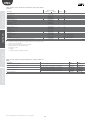
troubleshouting
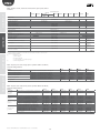
Cylinders
Cylinders (item 1)
CY0S1A0000
CY0S1A0000
CY0S1A0000
CY0S1A0000
CY0S1B0000
CY0S1C0000
CY0S1B0000
CY0S1C0000
CY0S1C0000
CY0S1D0000
Rated steam flow
3.5 lbs/h
3.5 lbs/h
5.5 lbs/h
5.5 lbs/h
3.5 lbs/h
3.5 lbs/h
7 lbs/h
7 lbs/h
12 lbs/h
12 lbs/h
1.6 kg/h
1.6 kg/h
2.5 kg/h
2.5 kg/h
1.6 kg/h
1.6 kg/h
3.2 kg/h
3.2 kg/h
5.4 kg/h
5.4 kg/h
Vac single-phase
110
110
110
110
230
230
230
230
230
230
Supply water conductivity (μS/cm)
normal
350-1250
low
125-350
normal
350-1250
low
125-350
normal
350-1250
low
125-350
normal
350-1250
low
125-350
normal
350-1250
low
125-350
KITCY0FG00
Notes
Default in compactSteam
Default in compactSteam
Default in compactSteam
Default in compactSteam
Default in compactSteam
Internal filter and gasket valid for all cylinders
Tab. 2.b
“Service humidification” +030220486 - rel. 1.0 - 01.09.2008
10
ENG
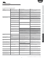
Action
Unit disabled
Red LED
OFF
EE
Internal memory error
Contact the service centre
ON
E0
Control board configuration not valid
Unit disabled
ON
E1
High current alarm
Unit disabled
ON
E2
Low production, low conductivity of the
supply water or excessive foam/lime scale
in the cylinder
Unit disabled.
Press the “reset/sel” button for 1 second
to delete the alarm
ON
E4
Fill alarm, water not filling or fill too slow
(the current does not increase within the
set time)
Press the “reset/sel” button for 1 second
to delete the alarm; otherwise, the
signal will be automatically reset every
10 minutes until the supply water is
available again.
ON
E5
Drain alarm, cannot perform the drain (the
Press the “reset/sel” button for 1 second
current does not decrease within the set
to delete the alarm
time)
ON
E6
Cylinder exhausted (critical performance)
E7
Foam detected
E9
High temperature of the control device
(above 80°C / 176°F)
The signal is reset automatically if
compactSteam can satisfy demand,
otherwise turn the unit off and on again.
Press the “reset/sel” button for 1 second
to delete the alarm
The signal is automatically reset if the
temperature falls below 80 °C / 176 °F.
Alarm relay Notes
OFF
Jumper terminals AB-AB
Have the unit reprogrammed by the
ON
service centre
Have the unit reprogrammed by the
ON
service centre
1. Turn off ;
2. Check the connections;
3. Check the cylinder (no bridges of lime
ON
scale between the electrodes);
4. Check that the electrodes are not
shorted.
Check the conductivity of the supply
water and if necessary replace the
ON
cylinder with the low conductivity
version.
1. Check the water supply and the fill
valve;
2. Check for any leaks from the drain
valve;
3. Make sure the filter on the fill solenoid
valve is not blocked;
4. Check that the steam outlet is
ON
not working against excessive
backpressure, preventing the flow of
water into the cylinder by gravity;
5. Check that the steam outlet hose
is not choked or that there are no
pockets of condensate;
6. Check that the power cables are
connected to the cylinder.
1. Make sure the drain valve is not
blocked
ON
2. Check that there are no blockages in
the drain connection.
OFF
OFF
Replace the cylinder (urgent)
OFF
OFF
If the problem persists, perform a number
of cleaning cycles
OFF
OFF
Replace the control device.
Tab. 3.a
11
“Service humidification” +030220486 - rel. 1.0 - 01.09.2008
spare parts
Description
Remote ON/OFF open
alarm table
Display
--
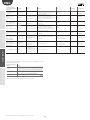
troubleshouting
In the event of alarms, the red LED flashes, the alarm relay closes, activating
the remote signal (if installed) and the alarm code flashes on the display.
There are two types of alarms: warnings and shutdown alarms. The
former can be deleted by pressing the “reset/sel” button for 2 s, while the
latter are displayed until maintenance is performed. Multiple alarms flash
in sequence, alternating with the main display.
The table below (Tab. 3.a) shows all the alarm codes, with a description of
the problems that cause these and the actions required to restore normal
operation.
maintenance
3. Alarms
ENG
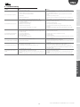
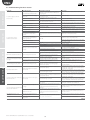
4. Troubleshouting
alarm table
spare parts
maintenance
Problem
1. No electrical power
2. Humidifier ON/OFF switch in position 0 (off )
3. Control connectors badly connected
4. Broken fuses
5. Controller fault
Solution
1. Check the protection devices upstream from the humidifier
and the presence of power
2. Close the ON/OFF switch: position I (on)
3. Check that the connectors are properly inserted in the terminal
block
4. Check the condition of the fuses
5. Check that this is activated and the correct voltage is
connected
The humidifier does not start
1. Remote ON/OFF contact open
2. The humidistat has not been connected correctly
3. Humidistat fault
4. Control signal not compatible with the type set
5. Value measured by the sensor/sensors higher than the
corresponding set point
1. Close the ON/OFF contacts (terminals AB-AB)
2. Check the external connections
3. Replace the humidistat
The humidifier fills with water without
producing steam
1. High steam backpressure
2. Fill valve filter blocked
3. Minerals in the fill tank
4. Leaks from the drain solenoid valve
The humidifier wets the duct
1. Distributor not installed correctly (too near the top of the
duct or the condensate return is blocked)
2. System oversized
3. Humidifier active when the fan in the duct is off
1. Check that the steam hose is not twisted or curved
downwards, thus trapping the condensate
2. Clean the fill valve filter
3. Clean the fill tank
4. Check the voltage on the drain solenoid valve and/or replace
the drain solenoid valve
1. Check that the steam distributor is installed correctly
2. Decrease the set steam production
3. Check the connection of the device (flow switch or differential
pressure switch) slaving the humidifier to the fan in the duct
The humidifier wets the floor below
1. Humidifier drain blocked
2. The supply water or overflow circuit has leaks
3. The condensate drain hose pipe does not carry the water
to the tank
4. The steam hose is not fastened to the cylinder correctly
1. Clean the drain circuit and the fill tank
2. Check the entire water circuit
3. Check the correct position of the condensate drain hose in the
drain tank
4. Check the fastening of the hose clamps on the steam outlet
The humidifier does not start
Cause
Sparks form inside the cylinder a few hours 1. The supply water contains considerable quantities of iron,
after starting
copper or other conductive contaminants.
The cylinder fills with water and drains
continually, without producing steam
1. The minerals have formed a bridge between the
electrodes.
2. Backpressure from the steam hoses or the duct.
3. The flow controller on the fill valve is broken or not
calibrated.
4. High conductivity of the water.
5. Excessive foam forms.
1. If using a softener, check the salts used. If these contain
additives, stop use, rinse all the lines and use non-softened
water.
2. Check the electrodes in the cylinder to make sure they have
not been damaged during transport.
1. Replace the cylinder.
2. Check if the steam hoses have twists or sags that may trap the
condensate.
3. Replace the fill valve.
4. Consider using a mixture of demineralised water and untreated
water.
5. Check the cylinder and replace it if exhausted.
troubleshouting
Tab. 4.a
“Service humidification” +030220486 - rel. 1.0 - 01.09.2008
12
ENG
humiSteam basic
Umidificatori
Humidifiers
Content
HUMISTEAM BASIC
15
1. Maintenance ...........................................................................................................15
1.1 Cleaning and maintenance of the cylinder........................................15
1.2 Mechanically draining the water in the cylinder ...........................15
1.3 Cylinder connection, three-phase models UE025 to UE065 ..15
1.4 Cleaning and maintenance of the other components ...............16
2. Spare parts ..............................................................................................................17
2.1 Spare parts for models UE001 to UE018 ..............................................17
2.2 Spare parts for models UE025 to UE065 ..............................................19
3. Allarms ........................................................................................................................21
13
“Service humidification” +030220486 - rel. 1.0 - 01.09.2008
ENG
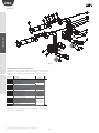
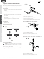
1. Maintenance
1.2 Mechanically draining the water in the cylinder
1.1 Cleaning and maintenance of the cylinder
Drain due to gravity without activating the humidifier, recommended if:
• humidifier decommissioned;
• to empty the cylinder without switching the humidifier on.
Replacement
Important: he cylinder must be only be replaced by qualified
personnel, and with the humidifier unplugged from the power
supply.
In normal conditions, the disposable cylinders should be replaced after
one year (or 2500 hours of operation, if cleaned periodically), while the
openable cylinders last 5 years (or 10,000 hours of operation, if cleaned
periodically). They must be replaced immediately – even before the
specified intervals – if any anomalies occur. For example, when the lime
scale inside the cylinder prevents the correct flow of electric current.
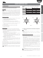
Mechanical drain:
• make sure that the humidifier is not powered;
• remove the cover;
• activate the mechanical device under the cylinder (see part A, Fig. 1.a).
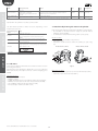
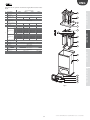
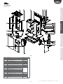
Models UE001 to UE018
maintenance
HUMISTEAM BASIC
Models UE025 to UE065
spare parts
A
A
Replacement procedure::
1. empty all the water;
2. turn off the humidifier (switch “0”), and open the mains disconnect
switch on the power supply (safety procedure);
3. wait for the humidifier and the cylinder to cool down;
4. remove the front cover;
5. disconnect the electrical cables from the cylinder;
6. release the cylinder from the locking device and lift it to remove it;
7. insert the new cylinder (make sure that the model and the power
supply of the new cylinder correspond to the rated data);
8. fasten the cylinder;
9. reconnect the electrical cables to the cylinder;
10. replace the front cover;
11. switch on the humidifier;
12. reset cylinder operating hour counter;
13. Activate the wash new cylinder procedure, pressing ENTER + DOWN
for 5 seconds
Fig. 1.a
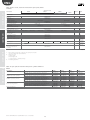
production
(kg/h)
75/350 μS/cm
350/1250 μS/cm
75/350 μS/cm
350/1250 μS/cm
75/350 μS/cm
350/1250 μS/cm
75/350 μS/cm
350/1250 μS/cm
25
35
45
65
Periodical checks
• After one hour of operation: check for any significant water leaks.
• Every 15 days or no more than 300 operating hours: check operation,
the absence of significant water leaks, the general conditions of
the casing. Check that during operation there are no arcs or sparks
between the electrodes.
• Every 3 months or no more than 1000 operating hours:
- disposable cylinders: check operation, the absence of significant
water leaks and if necessary replace the cylinder;
- openable cylinders: if there are significantly blackened areas, check
the deposits on the electrodes and clean them, using the specific
electrode and gasket kit.
• Every year or no more than 2500 operating hours:
- disposable cylinders: replace;
- openable cylinders: if there are significantly blackened areas, check
the deposits on the electrodes and clean them, using the specific
electrode and gasket kit.
• After 5 years or no more than 10,000 operating hours: replace the
openable cylinder.
After extended operation, or when using water rich in salts, the solid
deposits that naturally form on the electrodes may grow until attaching
to the inside wall of the cylinder. If these deposits are conductive the heat
generated may overheat the plastic until it melts, with the risk of very hot
water being released.
power supply (V)
230
400
A
B
B
B
A
B
A
B
A
A
A
B
/
A
/
B
conductivity (μS/cm)
Tab. 1.a
alarm table
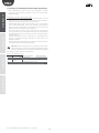
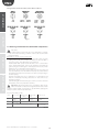
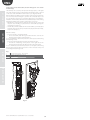
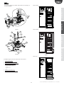
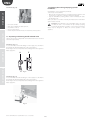
1.3 Cylinder connection, three-phase models UE025 to
UE065
A
B
2
3
3
3
E
1
2
D
C
3
E
D
F
F
C
A
B
A
2
1
B
2
1
1
Fig. 1.b
Cylinder connection for single-phase, three-phase UE01
to UE018 models
Important: In the event of water leaks, disconnect the power
supply from the humidifier as the water may conduct electricity.
Fig. 1.c
15
“Service humidification” +030220486 - rel. 1.0 - 01.09.2008
troubleshouting
The cable ends must be tightened with the top nut to 3 Newton • m.
(units with BL*T5* cylinder only)
ENG
1.4 Cleaning and maintenance of the other components
spare parts
maintenance
• when cleaning plastic components do not use detergents or solvents;
• scale can be removed using a solution of 20% acetic acid and then
rinsing with water.
Maintenance checks on other components:
fill solenoid valve. After having disconnected the cables and the
tubing, remove the solenoid valve and make sure the inlet filter is
clean; if necessary, clean with water and a soft brush;
manifold with drain pump. Check that there are no solid residues
in the cylinder attachment, remove any impurities. Check that the
gasket (o-ring) is not damaged or cracked, replace if necessary. Check
that there are no solid residues in the drain hose;
drain pump. Disconnect the power supply, remove the pump and
clean any impurities. Clean the tank from any deposits and check that
the water flows freely from the tank to the drain (corresponding to
the drain pump);
fill tank. Check that there are no obstructions or solid particles and
that the conductivity measuring electrodes are clean, remove any
impurities and rinse;
internal tubing kit. Check that the pipes and hoses are free and clear
of impurities, remove any impurities and rinse.
Important: after having replaced or checked the water circuit,
make sure that the connections are tight. Restart the unit and run
a number of fill and drain cycles (from 2 to 4), after which, applying
the safety procedure, check for any water leaks.
Fuses
F1 e F2
F3
F4
UE001...018
UE 025...065 (400 V)
UE025...045 (230V)
1 A fast-blow, 10,3x38
2 A fast-blow, 10,3x38
1 A fast-blow, 5x20
1 A fast-blow, 10,3x38
ceramic
2,5 A T fast-blow 5x20 ceramic
Tab. 1.b
troubleshouting
alarm table
Fuses in the auxiliary circuits
“Service humidification” +030220486 - rel. 1.0 - 01.09.2008
16
ENG
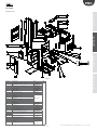
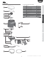
2. Spare parts
1
2
3
4
5
6
7
8
9
10
11
12
13
14
15
16
2
4
3
5
alarm table
1
fill tank
internal tubing kit
fill solenoid valve kit
cylinder
manifold with drain pump
plastic base
plastic humidifier top
TAM (transformer for measuring the current)
transformer
contactor
fuse holder F1-F2
electronic controller
power terminals
fuse holder F3
switch
terminal with display
spare parts
Key to Figs. 2.a and 2.b:
maintenance
2.1 Spare parts for models UE001 to UE018
6
troubleshouting
Fig. 2.a
Fig. 2.b
17
“Service humidification” +030220486 - rel. 1.0 - 01.09.2008
ENG
spare parts
maintenance
Table of water circuit, electrical and electronic spare parts, UE001
to UE018
spare part code
UE005
230-400
UE008 UE009
230 1ph
3ph
position
figure
1
3
2
6
7
5
2.a
2.a
2.a
2.b
2.b
2.a
UEKTR10000
UEYxxv0z0i(2)
URKFH10000
UEKFH10000
16
8
10
9
13
11
14
F1 - F2 230 to 400 Vac power fuses
UEKFUSE100
-
F3 Pump fuse
UEKFUSE200
-
F4 Transformer secondary fuse
URKFUSE500
-
2.b
2.b
2.b
2.b
2.b
2.b
2.b
see wiring
diagrams
see wiring
diagrams
see wiring
diagrams
Connection cable between terminal and
electronic controller
S90CONN002
-
UE001
UE003
UE010
UE015
UE018
Water circuit
Fill tank + conductivity meter
Fill solenoid valve kit
Internal tubing kit
Plastic humidifier base
Plastic humidifier top
Assembled f/d manifold + 230V pump
UEKVASC100
KITVC10006
UEKT10000S
KITVC10011
UEKT10000M
UEKBOTTOM0
UEKTOP0000
UEKDRAIN01
Electrical and electronics
Display terminal
TAM (current transformer)
Contactor
Power transformer: 230-400/24 V
Electronic controller (1)
Fuse carrier (F1,F2)
Fuse carrier (F3)
HCTLEYW0w0 (3)
UEKTAM0000
UEKCONT100
UEKCONT200
alarm table
Tab. 2.a
(1) when ordering, as well as the controller code specify the complete code and serial
number of the humidifier.
(2)
xx: kg/h (01,......65)
v: power supply
z: match digit board
i: 0 single package / 1 multiple package
(3)
w: match digit terminal
Table of spare part codes, Single-phase cylinders UE001 to UE009,
electrode and gasket kit
Model
UE001
UE003
UE005
UE009
STANDARD disposable cylinders
200/230 Vac 1~, conductivity 350 to 1250 μS/cm
BL0S1F00H2
BL0S1F00H2
BL0S2E00H2
BL0S3F00H2
SPECIAL disposable cylinders
200/230 Vac 1~, conductivity 75 to 350 μS/cm
200/230 Vac 1~, conductivity 75 to 350 μS/cm
200/230 Vac 1~, conductivity 350 to 1250 μS/cm
200/230 Vac 1~, conductivity 75 to 350 μS/cm
200/230 Vac 1~, conductivity 350 to 1250 μS/cm
BL0S1E00H2
BLCS1E00W2
BLCS1F00W2
KITBLCS1E2
KITBLCS1F2
KITBLC1FG0
BL0S1E00H2
BLCS1E00W2
BLCS1F00W2
KITBLCS2E2
KITBLCS2F2
KITBLC2FG0
BL0S2E00H2
BLCS2E00W2
BLCS2E00W2
KITBLCS2E2
KITBLCS2E2
KITBLC2FG0
BL0S3E00H2
BLCS3E00W2
BLCS3F00W2
KITBLCS3E2
KITBLCS3F2
KITBLC3FG0
troubleshouting
SPECIAL openable cylinders
Electrode and gasket kit
Filter gasket kit
Tab. 2.b
Table of spare part codes, three-phase cylinders UE003 to UE018,
electrode and gasket kit
Model
STANDARD
disposable
cylinders
UE003
UE005
UE008
UE010
UE015
200/230 VAC 3~, conductivity 350 to 1250 μS/cm
BL0T1B00H2
BL0T2A00H2
BL0T2A00H2
BL0T3A00H2
BL0T3A00H2
400 VAC 3~, conductivity 350 to 750 μS/cm
BL0T1C00H2
BL0T2C00H2
BL0T2C00H2
BL0T3C00H2
BL0T3C00H2
BL0T3C00H2
BL0T1A00H2
BL0T1A00H2
BL0T1D00H2
BLCT1A00W2
BLCT1A00W2
BLCT1C00W2
BLCT1D00W2
KITBLCT1A2
KITBLCT1B2
KITBLCT1A2
KITBLCT1C2
KITBLCT1D2
KITBLC1FG0
BL0T2A00H2
BL0T2B00H2
BL0T2D00H2
BLCT2A00W2
BLCT2B00W2
BLCT2C00W2
BLCT2D00W2
KITBLCT2A2
KITBLCT2A2
KITBLCT2B2
KITBLCT2C2
KITBLCT2D2
KITBLC2FG0
BL0T2A00H2
BL0T2B00H2
BL0T2D00H2
BLCT2A00W2
BLCT2B00W2
BLCT2C00W2
BLCT2D00W2
KITBLCT2A2
KITBLCT2A2
KITBLCT2B2
KITBLCT2C2
KITBLCT2D2
KITBLC2FG0
BL0T3A00H2
BL0T3B00H2
BL0T3D00H2
BLCT3A00W2
BLCT3B00W2
BLCT3C00W2
BLCT3D00W2
KITBLCT3A2
KITBLCT3A2
KITBLCT3B2
KITBLCT3C2
KITBLCT3D2
KITBLC3FG0
BL0T3A00H2
BL0T3B00H2
BL0T3D00H2
BLCT3A00W2
BLCT3B00W2
BLCT3C00W2
BLCT3D00W2
KITBLCT3A2
KITBLCT3A2
KITBLCT3B2
KITBLCT3C2
KITBLCT3D2
KITBLC3FG0
-BL0T3B00H2
BL0T3D00H2
-BLCT3B00W2
BLCT3C00W2
BLCT3D00W2
--KITBLCT3B2
KITBLCT3C2
KITBLCT3D2
KITBLC3FG0
200/230 VAC 3~, conductivity 75 to 350 μS/cm
SPECIAL disposable
400 VAC 3~, conductivity 75 to 350 μS/cm
cylinders
400 VAC 3~, conductivity 750 to 1250 μS/cm
200/230 VAC 3~, conductivity 75 to 350 μS/cm
SPECIAL openable 400 VAC 3~, conductivity 75 to 350 μS/cm
400 VAC 3~, conductivity 350 to 750 μS/cm
cylinders
400 VAC 3~, conductivity 750 to 1250 μS/cm
Electrode kit 200/230 Vac 3~, 75 to 350 μS/cm
Electrode kit 200/230 Vac 3~, 350 -1250 μS/cm
Electrode and
Electrode kit 400 Vac 3~, 75 - 350 μS/cm
Electrode kit 400 Vac 3~, 350 - 750 μS/cm
gasket kit
Electrode kit 400 Vac 3~, 750 - 1250 μS/cm
Filter gasket kit
UE018
--
Tab. 2.c
“Service humidification” +030220486 - rel. 1.0 - 01.09.2008
18
ENG
2.2 Spare parts for models UE025 to UE065
spare parts
drain circuit
fill solenoid valve kit
internal tubing kit
conductivity meter
drain pump kit
manifold
drain pump hose
cylinder
TAM (transformer for measuring the current)
contactor
transformer
fuse carrier
electronic controller
power terminals
cable clamp
switch
terminal with liquid crystal display (fitted on the cover of the
electrical compartment)
alarm table
1
2
3
4
5
6
7
8
9
10
11
13
14
15
16
17
18
maintenance
Key:
troubleshouting
Fig. 2.c
Fig. 2.d
19
“Service humidification” +030220486 - rel. 1.0 - 01.09.2008
ENG
Table of water circuit, electrical and electronic spare parts, UE025
to UE065
maintenance
description
UE025
230 V
400 V
230V
spare part code
UE035
400V
UE045
400 V
position
figure
2.c
2.c
2.c
KITVC10070
UEKDC10000
7
6
5
3
4
2
1
2.b
2.d
URKCONT300
18
9
10
230 V
UE065
Water circuit
Drain pump hose
Manifold
Drain pump kit
Internal tubing kit
Double check valve kit
Conductivity meter kit
Fill solenoid valve kit
Drain circuit
UEKDH00000
UEKCOLL000
KITPSE0000
UEKT10000L
UEKT1000XL
FWHDCV0000
KITCN00000
KITVC10058
UEKDC00000
2.c
2.c
spare parts
Electrical and electronics
Display terminal
TAM (current transformer)
Contactor
Power transformer:
230/400-24V
Electronic controller
Fuse carrier
Pump control relay
F1 - F2 230 to 400Vac power
fuses
F3 Pump fuse
HCTLEYF0w0 (3)
UEKTAM0000
URKCONT300
UEKFUSE300
UEKCONT200
UEKFUSE100
URKCONT300
UEKFUSE300
URKCONT400
UEKTR10000
11
2.d
UEYxxv0z0i(2)
URKFH20000
UEKRD00000
14
13
12
2.d
2.d
2.d
UEKFUSE100
-
UEKFUSE100
UEKFUSE300
UEKFUSE100
UEKFUSE100 -
F4 Transformer secondary fuse
URKFUSE500
-
Connection cable between
terminal and electronic
controller
S90CONN002
-
see wiring
diagrams
see wiring
diagrams
see wiring
diagrams
troubleshouting
alarm table
Tab. 2.d
1.
2.
3.
when ordering, as well as the controller code specify the complete
code and serial number of the humidifier.
xx: kg/h (01,......65)
v: power supply
z: match digit board
i: 0 single package / 1 multiple package
w: match digit terminal
Table of spare parts for standard and special cylinders UE025 to
UE065
Description
STANDARD disposable cylinders
SPECIAL disposable cylinders
SPECIALI openable cylinders
Electrode and gasket kit
200/230V 3ph cylinder, conductivity 350 to 1250 μS/cm
400V 3ph cylinder, conductivity 350 to 1250 μS/cm
200/230V 3ph cylinder, conductivity 75 to 350 μS/cm
400V 3ph cylinder, conductivity 75 to 350 μS/cm
200/230V 3ph cylinder, conductivity 75 to 350 μS/cm
200/230V 3ph cylinder, conductivity 350 to 1250 μS/cm
400V 3ph cylinder, conductivity 75 to 350 μS/cm
400V 3ph cylinder, conductivity 350 to 1250 μS/cm
200/230V 3ph cylinder, conductivity 75 to 350 μS/cm
200/230V 3ph cylinder, conductivity 350 to 1250 μS/cm
400V 3ph cylinder, conductivity 75 to 350 μS/cm
400V 3ph cylinder, conductivity 350 to 1250 μS/cm
Gasket and filter kit
UE025
BL0T4C00H2
BL0T4D00H2
UE035
BL0T4B00H2
BL0T4D00H2
UE045
BL0T5A00H1
BL0T4C00H2
UE065
BL0T5C00H0
BL0T4B00H2
BL0T4C00H2
BLCT4B00W2
BLCT4C00W2
BLCT4C00W2
BLCT4D00W2
KITBLCT4B2
KITBLCT4C2
KITBLCT4C2
KITBLCT4D2
KITBLC4FG0
BL0T4B00H2
BL0T4C00H2
BLCT4B00W2
BLCT4B00W2
BLCT4C00W2
BLCT4D00W2
KITBLCT4B2
KITBLCT4B2
KITBLCT4C2
KITBLCT4D2
KITBLC4FG0
BL0T5A00H1
BL0T4B00H2
BLCT5A00W0
BLCT5A00W0
BLCT4B00W2
BLCT4C00W2
KITBLCT5A0
KITBLCT5A0
KITBLCT4B2
KITBLCT4C2
KITBLC4FG0
-BL0T5B00H0
--BLCT5B00W0
BLCT5C00W0
--KITBLCT5B0
KITBLCT5C0
KITBLC5FG0
Tab. 2.e
“Service humidification” +030220486 - rel. 1.0 - 01.09.2008
20
ENG
3. Allarms
meaning
E0
calibration parameter
internal memory error
software verification errora
E1
EH
-
-
parameter configuration
error
excess current
causes
error in the parameters user
red LED signal
on board (*)
solution
reset (press)
alarm relay
effect
activation
if the problem persists,
contact the CAREL service
center
--
yes
humidification
stopped
3 fast flashes
--
yes
humidification
stopped
4 fast flashes
yes
humidification
stopped
2 fast flashes
yes
humidification
stopped
4 slow flashes
no
signal only
7 fast flashes
humidification
stopped for 10
minutes only
3 slow flashes
yes
humidification
stopped
5 slow flashes
no
signal only
6 slow flashes
no
signal only
10 slow flashes
if the problem persists,
contact the CAREL service
center
1. check the operation of
the drain pump
over-current at the electrodes;
probable electrode malfunction 2. check the seal of the
or water conductivity
fill electrovalve when not AUTO
temporarily too high (especially
energised
when starting after a short stop)
(if terminal not
connected)
maintenance
code display and
symbol
excessive reduction in
production , or cylinder
completely depleted or water
CY
cylinder life pre-alarm
the cylinder full limit of 1500 h
perform maintenance and/ (the alarm is
(default)
or replace the cylinder
reactivated
Perform maintenance on
ESC
the cylinder
ESC
after 50 hrs)
EF
no water
Ed
failed drain
CP
cylinder being depleted
signal
CL
cylinder depleted signal
EA
foam
Mn
end of cylinder life
EU
Check:
water supply and fill
valve;
whether the manual
drain is open;
blockage of the filter on
the fill solenoid valve;
whether there is
excessive backpressure in
steam outlet, preventing
the flow of water into the
cylinder by gravity;
that the steam outlet
hose is not choked or
that there are no pockets
of condensate;
that the power cables are
connected to the cylinder
cylinder full
yes
automatic
(in 10
(after 10
minute
minute
waiting
waiting time)
time)
check the drain pump and
ESC
drain connection
cylinder life ending,
perform maintenance and/ ESC
or replace the cylinder
cylinder life ended, perform
maintenance and/or
-replace the cylinder
excessive foam in the cylinder
during boiling.
the formation of foam is
generally due to the presence
of surfactants in the water
(lubricants, solvents, detergents,
water treatment agents,
softeners) or an excessive
concentration of dissolved salts.
1. drain the water supply
lines
2. clean the cylinder
3. check for the presence of
ESC
softeners
(in this case, use another
type of water
or reduce the softening)
the cylinder has exceeded
the limit of 2000 hours,
replace the cylinder
with the machine off :
reset hour
counter
1. check for any leaks
from the fill electrovalve
or the condensate return
pipe
excessive water level when unit
2. check that the level
-producing steam
sensors are clean
total shut-down pipe
2. check that the level
sensors are clean
total shut-down
21
no
signal only
9 slow flashes
yes
humidification
stopped
8 fast flashes
no
signal only
8 slow flashes
“Service humidification” +030220486 - rel. 1.0 - 01.09.2008
alarm table
no production
troubleshouting
EP
spare parts
3. drain part of the water
and re-start
ENG
spare parts
maintenance
code display and
symbol
meaning
causes
solution
reset (press)
high conductivity
red LED signal
on board (*)
(if terminal not
connected)
no (b5)
signal only
2. if the problem persists,
change the
source of supply water or
install a
suitable treatment
high supply water conductivity system
AUTO
(demineralisation, even
partial).
N.B.: the problem will not
be resolved
by softening the supply
water.
yes (b6)
humid. stopped
Cable interrupted /
disconnected / improperly
connected.
ESC
yes
humidification
stopped
7 slow flashes
1. check water conductivity
EC
alarm relay
effect
activation
check the reference signal
in 4 to 20 mA or 2 to 10V
mode)
5 fast flashes
E3
-
failed connection of
modulating signal
PC
-
cylinder cleaning started
signal
--
--
--
none
dr
-
cylinder drain activated
--
--
--
none
dr / TOT -
complete drain due to
inactivity
--
--
(both codes
alternate on
display)
AF
antifoam active
--
--
none
--
Press ESC once to mute the buzzer, press ESC a second time to reset the alarm.
(*) Quick flash: 0.2 seconds ON and 0.2 seconds OFF
Slow flash: 1 second ON and 1 second OFF
troubleshouting
alarm table
Tab. 3.a
“Service humidification” +030220486 - rel. 1.0 - 01.09.2008
22
ENG
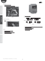
humiSteam Wellness
Umidificatori per bagni turchi
Humidifiers for steam baths
Content
HUMISTEAM WELLNESS
25
1. Maintenance ...........................................................................................................25
1.1 Cleaning and maintenance of the cylinder........................................25
1.2 Cylinder connection, three-phase models UE025 to UE065 ..25
1.3 Cleaning and maintenance of the other components..............25
2. Spare parts ..............................................................................................................27
2.1 Spare parts for models UE001 to UE018 ..............................................27
2.2 Spare parts, models UE025 to UE065....................................................29
3. Displaying the alarms.......................................................................................31
3.1 Info-menu................................................................................................................32
3.2 Mechanically draining the water in the cylinder ...........................32
23
“Service humidification” +030220486 - rel. 1.0 - 01.09.2008
ENG
1. Maintenance
1.2 Cylinder connection, three-phase models UE025 to
UE065
1.1 Cleaning and maintenance of the cylinder
production
(kg/h)
Replacement
Important: the cylinder must be only be replaced by qualified
personnel, and with the humidifier unplugged from the power
supply.
In normal conditions, the disposable cylinders should be replaced after
one year (or 2500 hours of operation, if cleaned periodically), while the
openable cylinders last 5 years (or 10,000 hours of operation, if cleaned
periodically). They must be replaced immediately – even before the
specified intervals – if any anomalies occur. For example, when the lime
scale inside the cylinder prevents the correct flow of electric current.
25
power supply (V)
230
400
A
B
B
B
A
B
A
B
A
A
A
B
/
A
/
B
/
B
conductivity (μS/cm)
125/350 μS/cm
350/1250 μS/cm
125/350 μS/cm
350/1250 μS/cm
125/350 μS/cm
350/1250 μS/cm
125/350 μS/cm
350/1250 μS/cm
350/1250 μS/cm
35
45
65
maintenance
HUMISTEAM WELLNESS
Tab. 1.a
A
B
2
3
3
3
E
1
2
D
F
C
3
E
D
F
C
A
B
A
2
1
B
2
1
1
Fig. 1.a
Periodical checks
• After one hour of operation: check for any significant water leaks.
• Every 15 days or no more than 300 operating hours: check operation,
the absence of significant water leaks, the general conditions of
the casing. Check that during operation there are no arcs or sparks
between the electrodes.
• Every 3 months or no more than 1000 operating hours:
- disposable cylinders: check operation, the absence of significant
water leaks and if necessary replace the cylinder;
- openable cylinders: if there are significantly blackened areas, check
the deposits on the electrodes and clean them, using the specific
electrode and gasket kit (see Tab. 2.c).
• Every year or no more than 2500 operating hours:
- disposable cylinders: replace;
- openable cylinders: if there are significantly blackened areas, check
the deposits on the electrodes and clean them, using the specific
electrode and gasket kit (see Tab. 2.c).
• After 5 years or no more than 10,000 operating hours: replace the
openable cylinder.
1.3 Cleaning and maintenance of the other components
Important:
alarm table
Replacement procedure:
1. empty all the water;
2. turn off the humidifier (switch “0”), and open the mains disconnect
switch on the power supply (safety procedure);
3. wait for the humidifier and the cylinder to cool down;
4. remove the front cover;
5. disconnect the electrical cables from the top of the cylinder;
6. release the cylinder from its fastening device and lift it up to remove
it;
7. insert the new cylinder (make sure that the model and the power
supply of the new cylinder correspond to the rated data);
8. fasten the cylinder;
9. reconnect the electrical cables to the top of the cylinder;
10. replace the front cover;
11. switch on the humidifier.
spare parts
The cable ends must be tightened with the top nut to 3 Newton • m.
• when cleaning the plastic components do not use detergents or
solvents;
rinsing with water.
Maintenance checks on other components:
fill solenoid valve (Fig. 2.a part. 3 and Fig. 2.c part. 2). After having
disconnected the cables and the tubing, remove the solenoid valve
and make sure the inlet filter is clean; if necessary, clean with water
and a soft brush;
manifold with drain pump (Fig. 2.a part. 5). Check that there are no
solid residues in the cylinder attachment, remove any impurities.
Check that the gasket (o-ring) is not damaged or cracked, replace if
necessary. Check that there are no solid residues in the drain hose;
drain pump (Fig. 2.c part. 4). Disconnect the power supply, unscrew
the fastening screws and remove any impurities (Fig. 2.a part. 6). Clean
the tank from any deposits and check that the water flows freely from
the tank to the drain (corresponding to the drain pump);
tank (Fig. 2.a part. 1). Check that there are no obstructions or solid
particles and that the conductivity measuring electrodes are clean,
remove any impurities and rinse;
internal pipe kit (Fig. 2.a part. 2 and Fig. 2.c part. 3). Check that the
pipes and hoses are free and clear of impurities, remove any impurities
and rinse.
After extended operation, or when using water rich in salts, the solid
deposits that naturally form on the electrodes may grow until attaching
to the inside wall of the cylinder. If these deposits are conductive the heat
generated may overheat the plastic until it melts, with the risk of very hot
water being released.
Important: In the event of water leaks, disconnect the power
supply from the humidifier as the water may conduct electricity.
Important: after having replaced or checked the water circuit,
make sure that the connections are tight. Restart the unit and run
a number of fill and drain cycles (from 2 to 4), after which, applying the
safety procedure, check for any water leaks.
25
“Service humidification” +030220486 - rel. 1.0 - 01.09.2008
troubleshouting
• scale can be removed using a solution of 20% acetic acid and then
ENG
Fuses
F1 & F2
F3
F41 (s 1)
F42 (s 2)
F5 & F6
AP1 & AP2
controller
fuse PF1
UE001 to 018
4 A fast-blow. 10.3x38
5 A T slow-blow 5x20 ceramic
2 Amp. T slow-blow 5x20 ceramic
1 A T slow-blow 5x20 glass
6.3 A T slow-blow 5x20 ceramic
2 A T slow-blow 5x20 glass
(minimum size of connection
cables 1.5 mm2)
UE 025 to 065
1 A fast-blow. 10.3x38
1 A fast-blow. 10.3x38
2.5 A T slow-blow 5x20 ceramic
1 A T slow-blow 5x20 glass
6.3 A T slow-blow 5x20 ceramic
2 A T slow-blow 5x20 glass
(minimum size of connection
cables 1.5 mm2)
Tab. 1.b
troubleshouting
alarm table
spare parts
maintenance
Fuses in the auxiliary circuits
“Service humidification” +030220486 - rel. 1.0 - 01.09.2008
26
ENG
2. Spare parts
1
2
3
4
5
6
7
8
9
10
11
12
13
14
15
16
17
18
2
4
3
5
alarm table
1
tank
internal pipe kit
fill solenoid valve kit
cylinder
manifold with drain pump
plastic base
plastic humidifier top
TAM (transformer for measuring the current)
transformer
contactor
fuse carrier
pCOe expansion board (controller I/O expansion)
microprocessor electronic controller
power terminals
utility terminal block
plastic base
switch
terminal with liquid crystal display
spare parts
Key to Figs. 2a and 2.b:
maintenance
2.1 Spare parts for models UE001 to UE018
6
troubleshouting
Fig. 2.a
7
8
9
10
11
12
13
14
15
16
17
18
Fig. 2.b
27
“Service humidification” +030220486 - rel. 1.0 - 01.09.2008
ENG
Table of water circuit, electrical and electronic spare parts, UE001
to 018
spare parts
maintenance
UE001
UE003
spare part code
UE008 UE009
UE005
UE010
UE015
UE018
position
figure
1
3
2
16
7
3
2.a
2.a
2.a and 2.c
2.b
2.b
2.a
11
8
2.b
2.b and 2.d
9
13
12
11
-
2.b and 2.d
2.b and 2.d
2.b
2.b and 2.d
see wiring diagrams
-
see wiring diagrams
-
see wiring diagrams
Water circuit
Fill tank + conductivity meter
Fill solenoid valve kit
Internal pipe kit
Plastic humidifier base
Plastic humidifier top
Assembled f/d manifold + pump
UEKVASC000
KITVC10006
UEKT10000S
KITVC10011
UEKT10000M
18C565A019
18C476A011
18C565A018
Electrical and electronics
Display terminal
TAM (current transformer)
Contactor
Power transformer: 230-400/24-24 V
Microprocessor electronic controller
pCOe expansion board (Controller I/O expansion)
Fuse carrier
F1 - F2 230 to 400 Vac power fuses
HCT1EWF000
09C565A042
0203013AXX
09C565A016
HCA0EW0000
PCOE00TLN0
0606192AXX
0605321ALG
0605581AXX (F41)
0605620AXX (F42)
0605615AXX
0605595AXX
0203012AXX
F4 Transformer secondary fuse (F41)
F5 - F6 pCOe fuse
AP1 - AP2 Terminal fuse
Connection cable between terminal and
electronic controller
PF1 Controller fuse
S90CONN002
-
0605604AXX
-
see wiring diagrams
Tab. 2.a
troubleshouting
alarm table
Table of spare part codes, single-phase cylinders UE001 to 005,
electrode and gasket kit
Model
STANDARD disposable cylinders
SPECIAL disposable cylinders
SPECIAL openable cylinders
Electrode and gasket kit
200/230 Vac 3~, conductivity 350 to 1250 μS/cm
200/230 Vac 3~, conductivity 125 to 350 μS/cm
200/230 Vac 3~, conductivity 125 to 350 μS/cm
200/230 Vac 3~, conductivity 350 to 1250 μS/cm
200/230 Vac 3~, conductivity 125 to 350 μS/cm
200/230 Vac 3~, conductivity 350 to 1250 μS/cm
Electrode gasket kit
UE001
BL0S1F00H1
UE003
BL0S1F00H1
UE005
BL0S2F00H0
UE009
BL0S3F00H0
BL0S1E00H1
BLCS1E00W1
BLCS1F00W1
KITBLCS1E0
KITBLCS1F0
KITBLC1FG0
BL0S1E00H1
BLCS1E00W1
BLCS1F00W1
KITBLCS2E0
KITBLCS2F0
KITBLC2FG0
BL0S2E00H0
BLCS2E00W0
BLCS2F00W0
KITBLCS2E0
KITBLCS2F0
KITBLC2FG0
BL0S3E00H0
BLCS3E00W0
BLCS3F00W0
KITBLCS3E0
KITBLCS3F0
KITBLC3FG0
Tab. 2.b
Table of spare part codes, three-phase cylinders UE003 to 018,
electrode and gasket kit
Model
STANDARD
disposable
cylinders
200/230 VAC 3~, conductivity 350 to 1250 μS/cm
UE003
BL0T1B00H1
UE005
BL0T2B00H0
UE008
BL0T2B00H0
UE010
BL0T3B00H0
UE015
BL0T3A00H0
UE018
BL0T3B00H0
400 VAC 3~, conductivity 350 to 750 μS/cm
BL0T1C00H1
BL0T2C00H0
BL0T2C00H0
BL0T3C00H0
BL0T3B00H0
BL0T3B00H0
BL0T1A00H1
BL0T1A00H1
BL0T1D00H1
BLCT1A00W1
BLCT1A00W1
BLCT1C00W1
BLCT1D00W1
KITBLCT1A0
KITBLCT1B0
KITBLCT1A0
KITBLCT1C0
KITBLCT1D0
KITBLC1FG0
BL0T2A00H1
BL0T2B00H0
BL0T2D00H0
BLCT2A00W1
BLCT2B00W0
BLCT2C00W0
BLCT2D00W0
KITBLCT2A0
KITBLCT2B0
KITBLCT2B0
KITBLCT2C0
KITBLCT2D0
KITBLC2FG0
BL0T2A00H1
BL0T2B00H0
BL0T2D00H0
BLCT2A00W1
BLCT2B00W0
BLCT2C00W0
BLCT2D00W0
KITBLCT2A0
KITBLCT2B0
KITBLCT2B0
KITBLCT2C0
KITBLCT2D0
KITBLC2FG0
BL0T3A00H1
BL0T3B00H0
BL0T3D00H0
BLCT3A00W1
BLCT3B00W0
BLCT3C00W0
BLCT3D00W0
KITBLCT3A0
KITBLCT3B0
KITBLCT3B0
KITBLCT3C0
KITBLCT3D0
KITBLC3FG0
BL0T3A00H1
BL0T3B00H0
BL0T3D00H0
BLCT3A00W1
BLCT3B00W0
BLCT3B00W0
BLCT3D00W0
KITBLCT3A0
KITBLCT3B0
KITBLCT3B0
KITBLCT3C0
KITBLCT3D0
KITBLC3FG0
BL0T3A00H1
BL0T3B00H0
BL0T3D00H0
BLCT3A00W1
BLCT3B00W0
BLCT3B00W0
BLCT3D00W0
KITBLCT3A0
KITBLCT3B0
KITBLCT3B0
KITBLCT3C0
KITBLCT3D0
KITBLC3FG0
SPECIAL
disposable
cylinders
200/230 VAC 3~, conductivity 125..350 μS/cm
400 VAC 3~, conductivity 125 to 350 μS/cm
400 VAC 3~, conductivity 750 to 1250 μS/cm
200/230 VAC 3~, conductivity 125..350 μS/cm
SPECIAL openable 400 VAC 3~, conductivity 125 to 350 μS/cm
400 VAC 3~, conductivity 350 to 750 μS/cm
cylinders
400 VAC 3~, conductivity 750 to 1250 μS/cm
Electrode kit 200/230 Vac 3~, 125/350 μS/cm
Electrode kit 200/230 Vac 3~, 350/1250 μS/cm
Electrode and
Electrode kit 400 Vac 3~, 125/350 μS/cm
Electrode kit 400 Vac 3~, 350/750 μS/cm
gasket kit
Electrode kit 400 Vac 3~, 750/1250 μS/cm
Electrode gasket kit
Tab. 2.c
“Service humidification” +030220486 - rel. 1.0 - 01.09.2008
28
ENG
2.2 Spare parts, models UE025 to UE065
1
7
2
3
drain circuit
fill solenoid valve kit
internal pipe kit
drain pump kit
manifold
cylinder
drain pump hose
TAM (transformer for measuring the current)
contactor
transformer
pCOe expansion board (controller I/O expansion)
pump control relay
fuse carrier
microprocessor electronic controller
power terminals
utility terminal block
cable clamp
switch
terminal with liquid crystal display (fitted on the cover of the
electrical compartment)
spare parts
1
2
3
4
5
6
7
8
9
10
11
12
13
14
15
16
17
18
19
6
maintenance
Key:
4
alarm table
5
Fig. 2.c
8
troubleshouting
9
10
11
12
13
14
15
16
17
18
19
Fig. 2.d
29
“Service humidification” +030220486 - rel. 1.0 - 01.09.2008
ENG
Table of water circuit, electrical and electronic spare parts, UE025
to UE065
maintenance
description
UE025
UE035
spare part code
UE045
400 V
230 V
UE065
position
figure
7
5
4
3
2
1
2.c
2.c
2.c
2.a and 2.c
2.c
2.c
19
11
8
2.b
2.d
2.b and 2.d
10
14
13
12
-
2.b and 2.d
2.b and 2.d
2.b and 2.d
2.d
see wiring diagrams
see wiring diagrams
see wiring diagrams
see wiring diagrams
Water circuit
Drain pump hose
Manifold
Drain pump kit
Internal pipe kit
Double check valve kit
Conductivity meter kit
Fill solenoid valve kit
Drain circuit
13C479A001
18C499A001
KITPS00000
UEKT10000L
KITVC10058
13C565A031
UEKT1000XL
FWHDCV0000
KITCN00000
KITVC10070
KITVC10070
KITVC10070
spare parts
Electrical and electronics
Display terminal
pCOe expansion board (controller I/O expansion)
TAM (current transformer)
Contactor (V= 400)
Power transformer: 230/400-24V
Microprocessor electronic controller
Fuse carrier
Pump control relay
F1 - F2 230 to 400Vac power fuses
F3 Pump fuse
F4 Transformer secondary fuse
HCT1EWF000
PCOE00TLN0
09C565A042
0203014AXX
09C565A044
HCA0EW0000
0606193AXX
0102001AXX
0605319AXX
0605319AXX
0605624AXX
0203013AXX
0203007AXX
F5 - F6 pCOe fuse
0605615AXX
-
AP1 - AP2 Terminal fuse
Connection cable between terminal and HHPC
PF1 Controller fuse
0605595AXX
S90CONN002
0605604XXX
-
see wiring diagrams
see wiring diagrams
alarm table
Tab. 2.d
Table of spare parts for standard and special cylinders UE025 to
UE065
Description
STANDARD disposable cylinders
SPECIAL disposable cylinders
troubleshouting
SPECIAL openable cylinders
Electrode and gasket kit
200/230V 3ph cylinder, conductivity 350 to 1250 μS/cm
400V 3ph Cylinder, conductivity 350 to 1250 μS/cm
200/230V 3ph Cylinder, conductivity 125 to 350 μS/cm
400V 3ph Cylinder, conductivity 125 to 350 μS/cm
200/230V 3ph Cylinder, conductivity 125 to 350 μS/cm
200/230V 3ph Cylinder, conductivity 350 to 1250 μS/cm
400V 3ph Cylinder, conductivity 125 to 350 μS/cm
400V 3ph Cylinder, conductivity 350 to 1250 μS/cm
200/230V 3ph Cylinder, conductivity 125 to 350 μS/cm
200/230V 3ph Cylinder, conductivity 350 to 1250 μS/cm
400V 3ph Cylinder, conductivity 125 to 350 μS/cm
400V 3ph Cylinder, conductivity 350 to 1250 μS/cm
Gasket kit
UE025
BL0T4C00H0
BL0T4C00H0
UE035
BL0T4B00H0
BL0T4D00H0
UE045
BL0T5A00H1
BL0T4C00H0
UE065
BL0T5C00H0
BL0T4B00H0
BL0T4C00H0
BLCT4B00W0
BLCT4C00W0
BLCT4C00W0
BLCT4C00W0
KITBLCT4B0
KITBLCT4C0
KITBLCT4C0
KITBLCT4D0
KITBLC4FG0
BL0T4B00H0
BL0T4C00H0
BLCT4B00W0
BLCT4B00W0
BLCT4C00W0
BLCT4D00W0
KITBLCT4B0
KITBLCT4C0
KITBLCT4C0
KITBLCT4D0
KITBLC4FG0
BL0T5A00H1
BL0T4B00H0
BLCT5A00W0
BLCT5A00W0
BLCT4B00W0
BLCT4C00W0
KITBLCT5A0
KITBLCT5A0
KITBLCT4B0
KITBLCT4C0
KITBLC4FG0
-BL0T5B00H0
--BLCT5B00W0
BLCT5C00W0
--KITBLCT5B0
KITBLCT5C0
KITBLC5FG0
Tab. 2.e
“Service humidification” +030220486 - rel. 1.0 - 01.09.2008
30
ENG
alarm
relay
manual
active
1. check that the supply hose and the internal hoses are not
blocked or choked and that there is sufficient pressure (0.1 to
0.8 MPa, 1 to 8 bars);
2. check the operation of the fill solenoid valve;
3. check that the steam outlet is not operating with excessive
backpressure, preventing the flow of water into the cylinder
by gravity;
4. check that the steam outlet hose is not choked and that
there are no pockets of condensate
automatic
(automatic
water return
procedure)
active
stop steam
production
Alarm: Ed
Drain alarm(Cylinder drain malfunction
OFF)
check the water drain circuits and the correct operation of the
electric drain pump
manual
active
stop steam
production
Alarm: EL
Low urrent
(Cylinder OFF)
power not available; when the unit is
activated no steam is produced
with the unit off and disconnected from the mains, check the
electrical connections.
manual
active
stop steam
production
Alarm: EH High
current (Cylinder
OFF)
1. check the operation of the electric drain pump;
probable fault in the electrodes or water
2. check the seal of the fill solenoid valve when not energised;
temporarily too conductive(especially
drain some of the water and re-start.
when restarting after a short stop)
manual
active
stop steam
production
manual
active
stop steam
production
Alarm: EP
Low Production
(cylinder OFF)
excessive reduction in steam production,
Perform maintenance on the cylinder
or excessive foam in the cylinder.
Alarm: EF
Lack of water
(cylinder OFF)
no water in the cylinder
Alarm: EC
High
conductivity
(Cylinder OFF)
high supply water conductivity
Warning: Ec
High conductivity
pre-alarm: high supply water
conductivity
Alarm: E=
High temp.
Alarm: E_
Low temp.
Alarm: E3
Probe 1 fault or
offline
Alarm: E4
Probe 2 fault or
offline
pre-alarm: high temperature
pre-alarm: low temperature
solution
1. check the limit threshold set;
2. switch the unit off and clean the electrodes that measure of
the conductivity of the water; if the problem persists, change
the origin of the supply water or use a suitable treatment
system (partial demineralisation).
Note: the problem is not resolved by softening the supply water
1. check the conductivity of the supply water, if necessary use a
suitable treatment system (partial demineralisation).
Note: the problem is not resolved by softening the supply water
check the operation of the probe and the high temperature
parameter
check the operation of the probe and the low temperature
parameter
automatic
automatic
automatic
not active
not active
not active
consequence
stop steam
production
signal only
signal only
signal only
1st probe disconnectedor faulty alarm
check the connection of the probe, and the type of probe
selected on the: “type of probe” screen (“Maint HW” submenu)
automatic
active
2nd probe disconnectedor faulty alarm
check the connection of the probe, and the type of probe
selected on the: “type of probe” screen (“Maint HW” submenu)
automatic
not active stop steam
production
Warning:
EA Foam cylinder
excessive foam in the cylinder during
boiling
the entrainment of foam is generally due to the presence of
surfactants in the water (lubricants, solvents, detergents, water
treatment agents, softeners) or an excessive concentration of
dissolved salts:
manual
1. drain the water supply lines;
2. clean the cylinder make sure a softener is not used (if so, use
another source of water or reduce the softening).
Warning:
CP Pre-exhaustion
cylinder
pre-alarm: cylinder being depleted
perform maintenance and/or replace the cylinder
manual
Alarm: EU
full cylinder (cylinder cylinder full with unit off
OFF)
with the unit off :
1. check for any leaks from the fill solenoid valve or the
condensate return from the hose, check that the level
sensors are clean
manual
active
stop steam
production
Warning: CL
Exhaustion cylinder
cylinder depleted
perform maintenance and/or replace the cylinder
manual
active
stop steam
production
Warning: CY
Cylinder
maintenance
recommended
cylinder maintenance recommended
perform maintenance and/or replace the cylinder
Alarm: Mn
Cylinder
maintenance
cylinder maintenance required
mandatory (cylinder
OFF)
Replace the cylinder
31
stop steam
production
not active signal only
not active signal only
manual
(reset
not active signal only
countertatore)
manual
(reset counter) active
stop steam
production
“Service humidification” +030220486 - rel. 1.0 - 01.09.2008
troubleshouting
meaning and cause
spare parts
reset
alarm
alarm table
From the alarm log submenu, press ENTER to display the alarms (type of
alarm, date and time)
The humidifier saves up to 200 alarms.
maintenance
3. Displaying the alarms
maintenance
ENG
alarm
meaning and cause
solution
reset
Clock board fault
Clock error
backup battery completely
discharged or general problems with
the clock
Electronic microprocessor controller installed inside the
humidifier electrical compartment
manual
Alarm: utility board
1 or 2
utilities board offline or faulty
- connect the board
- deactivate the utility functions relating to the alarm signal
automatic
consequence
not active signal only
active
signal only
Tab. 3.a
Cylinder OFF= the cylinder is not able to produce steam
3.2 Mechanically draining the water in the cylinder
The alarm button performs a number of actions, depending on how
many times it is pressed.
Action/Pressing the
button
spare parts
alarm
relay
first time
second time
third time
fourth time
Drain due to gravity without activating the humidifier, recommended if:
• the humidifier is decommissioned, to empty the cylinder without
switching on the humidifier;
• to eliminate the residual water following a drain cycle by pump.
Effect
display the alarm code;
if more than one alarm is active at the same time, the
codes are displayed in sequence by pressing UP or
DOWN.
if the cause of the alarm has been resolved, the alarm
is no longer displayed and the corresponding relay is
deactivated (if fitted)
the cause of the alarm has been resolved, the alarm is no
longer displayed, the corresponding relay is deactivated
and the display shows:
Mechanical drain:
• make sure that the humidifier is not powered;
• remove the cover;
• activate the mechanical device under the cylinder (see part. A Fig.
3.a).
Models UE001 to UE018
Models UE025 to UE065
return to the main screen
Tab. 3.b
troubleshouting
alarm table
A
A
3.1 Info-menu
Fig. 3.a
Series of screens that describe the functions and the use of the screens in
the management menu.
Enabling “info-menu” (disabled by default), all access to the submenus
will be preceded by a descriptive screen (to continue navigating, press
ENTER).
Other types of drains:
• manual (from “ON/OFF quick access” screen; and manual procedure;
• automatic (see par. “Automatic water drain“).
Enabling info-menu
From the “utility” submenu press:
• ENTER to confirm;
• DOWN until displaying the screen with the “enable info?” parameter;
• ENTER to move the cursor to the value of the parameter (YES/NO);
• UP or DOWN to enable the info-menu function (YES);
• ESC repeatedly to return to the “Main” screen;
“Service humidification” +030220486 - rel. 1.0 - 01.09.2008
32
ENG
humiSteam x-plus
Umidificatori
Humidifiers
Content
HUMISTEAM X-PLUS
35
1. Maintenance ...........................................................................................................35
1.1
1.2
1.3
1.4
Cleaning and maintenance of the cylinder ......................................35
Mechanically draining the water in the cylinder ...........................35
Cylinder connection, three-phase models UE001 to UE130 ..35
Cleaning and maintenance of the other components..............36
2. Spare parts ...............................................................................................................37
2.1 Spare parts for models UE001 to UE018 .............................................37
2.2 Spare parts for models UE025 to UE065 .............................................39
2.3 Spare parts for models UE090 to UE130 .............................................41
3. Allarms ........................................................................................................................43
33
“Service humidification” +030220486 - rel. 1.0 - 01.09.2008
ENG
water leaks and if necessary replace the cylinder;
1.1 Cleaning and maintenance of the cylinder
- openable cylinders: if there are significantly blackened areas, check
the deposits on the electrodes and clean them, using the specific
electrode and gasket kit.
• Every year or no more than 2500 operating hours:
- disposable cylinders: replace;
- openable cylinders: if there are significantly blackened areas, check
the deposits on the electrodes and clean them, using the specific
electrode and gasket kit.
• After 5 years or no more than 10,000 operating hours: replace the
openable cylinder.
After extended operation, or when using water rich in salts, the solid
deposits that naturally form on the electrodes may grow until attaching
to the inside wall of the cylinder. If these deposits are conductive the heat
generated may overheat the plastic until it melts, with the risk of very hot
water being released.
Replacement
Important: the cylinder must be only be replaced by qualified
personnel, and with the humidifier unplugged from the power
supply.
In normal conditions, the disposable cylinders should be replaced after
one year (or 2500 hours of operation, if cleaned periodically), while the
openable cylinders last 5 years (or 10,000 hours of operation, if cleaned
periodically). They must be replaced immediately – even before the
specified intervals – if any anomalies occur. For example, when the lime
scale inside the cylinder prevents the correct flow of electric current.
Replacement procedure:
1. empty all the water (cylinder replacement procedure, see
maintenance menu);
2. turn off the humidifier (switch “0”), and open the mains disconnect
switch on the power supply (safety procedure);
3. wait for the humidifier and the cylinder to cool down;
4. remove the front cover;
5. disconnect the electrical cables from the cylinder and steam hose;
6. release the cylinder from the locking device and lift it to remove it;
7. insert the new cylinder (make sure that the model and the power
supply of the new cylinder correspond to the rated data);
8. fasten the cylinder;
9. reconnect the electrical cables to the cylinder;
10. replace the front cover;
11. switch on the humidifier;
12. reset cylinder operating hour counter (see maintenance menu);
13. Activate the wash new cylinder procedure (see maintenance menu).
Important: In the event of water leaks, disconnect the power
supply from the humidifier as the water may conduct electricity.
conductivity (μS/cm)
75/350 μS/cm
350/1250 μS/cm
75/350 μS/cm
350/1250 μS/cm
75/350 μS/cm
350/1250 μS/cm
75/350 μS/cm
350/1250 μS/cm
75/350 μS/cm
350/1250 μS/cm
75/350 μS/cm
350/1250 μS/cm
35
65
1.2 Mechanically draining the water in the cylinder
90
Drain due to gravity without activating the humidifier, recommended if:
• humidifier decommissioned;
• to empty the cylinder without switching the humidifier on.
power supply (V)
230
400
A
B
B
B
A
B
A
B
A
A
A
B
/
A
/
B
/
A
/
B
/
A
/
B
130
Tab. 1.b
The cable ends must be tightened with the top nut to 3 Newton • m.
(units with BL*T5* cylinder only)
Mechanical drain:
• make sure that the humidifier is not powered;
• remove the cover;
• activate the mechanical device under the cylinder (see the figure
below).
A
B
2
3
3
3
E
1
Models UE025 to UE130
2
D
F
C
3
F
C
A
B
1
A
2
B
1
1
2
A
E
D
Fig. 1.b
A
Fig. 1.a
Periodical checks
• After one hour of operation: check for any significant water leaks.
• Every 15 days or no more than 300 operating hours: check operation,
the absence of significant water leaks, the general conditions of
the casing. Check that during operation there are no arcs or sparks
between the electrodes.
35
“Service humidification” +030220486 - rel. 1.0 - 01.09.2008
troubleshouting
production
(kg/h)
25
alarm table
1.3 Cylinder connection, three-phase models UE025 to
UE130
45
Models UE001 to UE018
spare parts
• Every 3 months or no more than 1000 operating hours:
- disposable cylinders: check operation, the absence of significant
1. Maintenance
maintenance
HUMISTEAM X-PLUS
ENG
spare parts
maintenance
Collegamento cilindro monofase, trifase UE001 a UE018
Fig. 1.c
1.4 Cleaning and maintenance of the other components
Important:
troubleshouting
alarm table
• when cleaning plastic components do not use detergents or solvents;
• scale can be removed using a solution of 20% acetic acid and then
rinsing with water.
Maintenance checks on other components:
fill solenoid valve. After having disconnected the cables and the
tubing, remove the solenoid valve and make sure the inlet filter is
clean; if necessary, clean with water and a soft brush;
manifold with drain pump. Check that there are no solid residues
in the cylinder attachment, remove any impurities. Check that the
gasket (o-ring) is not damaged or cracked, replace if necessary. Check
that there are no solid residues in the drain hose;
drain pump. Disconnect the power supply, remove the pump and
clean any impurities. Clean the tank from any deposits and check that
the water flows freely from the tank to the drain (corresponding to
the drain pump);
fill tank. Check that there are no obstructions or solid particles and
that the conductivity measuring electrodes are clean, remove any
impurities and rinse;
internal tubing kit. Check that the pipes and hoses are free and clear
of impurities, remove any impurities and rinse.
Important: after having replaced or checked the water circuit,
make sure that the connections are tight. Restart the unit and run
a number of fill and drain cycles (from 2 to 4), after which, applying the
safety procedure, check for any water leaks.
Fuses in the auxiliary circuits
Fuses
UE001 to 018
F1. F2
1 A fast-blow,
10.3x38
1 A fast-blow,
5x20 ceramic
2.5 A T slow-blow 5x20 ceramic
F3
F4
UE 025 to 045
(230V)
2 A fast-blow,
10.3x38
UE 025 to 065
UE 090 to 130
(400V)
1 A fast-blow,
2 A fast-blow,
10.3x38
10.3x38
1 A fast-blow, 10.3x38
4 A T slow-blow
5x20 in ceramic
Tab. 1.b
“Service humidification” +030220486 - rel. 1.0 - 01.09.2008
36
ENG
2. Spare parts
1
2
3
4
5
6
7
8
9
10
11
12
13
14
15
16
2
4
3
5
alarm table
1
fill tank
internal tubing kit
fill solenoid valve kit
cylinder
manifold with drain pump
plastic base
plastic humidifier top
TAM (transformer for measuring the current)
transformer
contactor
fuse holder F1-F2
electronic controller
power terminals
fuse holder F3
switch
terminal with display
spare parts
Key
maintenance
2.1 Spare parts for models UE001 to UE018
6
troubleshouting
Fig. 2.a
Fig. 2.b
37
“Service humidification” +030220486 - rel. 1.0 - 01.09.2008
ENG
Table of water circuit, electrical and electronic spare parts, UE001
to 018
maintenance
spare parts
spare part code
UE005
UE008 UE009
230-400 3ph 230 1ph
position
figura
1
3
2
6
7
5
2.a
2.a
2.a
2.b
2.a
2.a
UEKTR10000
HCzXxxxvi0(2)
URKFH10000
UEKFH10000
16
8
10
9
12
11
14
F1 - F2 230 to 400 Vac power fuses
UEKFUSE100
-
F4 Transformer secondary fuse
UEKFUSE200
-
F3 Pump fuse
URKFUSE500
-
2.b
2.b
2.b
2.b
2.b
2.b
2.b
see electrical
diagram
see electrical
diagram
see electrical
diagram
Connection cable between terminal and
electronic controller
S90CONN002
-
UE001
UE003
UE010
UE015
UE018
Parte idraulica
Fill tank + conductivity meter
Fill solenoid valve kit
Internal tubing kit
Plastic humidifier base
Plastic humidifier top
Assembled f/d manifold + 230V pump
UEKVASC000
KITVC10006
UEKT10000S
KITVC10011
UEKT10000M
UEKBOTTOM0
UEKTOP0000
UEKDRAIN01
Electrical and electronics
Display terminal
TAM (current transformer)
Contactor
Power transformer: 230-400/24 V
Electronic controller(1)
Fuse carrier (F1,F2)
Fuse carrier (F3)
HCT1EXW000
UEKTAM0000
UEKCONT100
UEKCONT200
Tab. 2.a
1. To make an order specify the complete product code and the serial
number of your humidifer.
alarm table
2. z: board version (A: basic version up to UE65; B: with espantion board
for UE90-130)
XX: kg/h (01...130)
v: voltage
i: 0 single packing; 1: multiple packing
Table of spare part codes, single-phase cylinders UE001 to 009,
electrode and gasket kit
Model
STANDARD disposable cylinders
troubleshouting
SPECIAL disposable cylinders
SPECIAL openable cylinders
Electrode and gasket kit
200/230 Vac 1~, conductivity 350 to 1250 μS/cm
200/230 Vac 1~, conductivity 75 to 350 μS/cm
200/230 Vac 1~, conductivity 75 to 350 μS/cm
200/230 Vac 1~, conductivity 350 to 1250 μS/cm
200/230 Vac 1~, conductivity 75 to 350 μS/cm
200/230 Vac 1~, conductivity 350 to 1250 μS/cm
Filter gasket kit
UE001
BL0S1F00H2
UE003
BL0S1F00H2
UE005
BL0S2E00H2
UE009
BL0S3F00H2
BL0S1E00H2
BLCS1E00W2
BLCS1F00W2
KITBLCS1E2
KITBLCS1F2
KITBLC1FG0
BL0S1E00H2
BLCS1E00W2
BLCS1F00W2
KITBLCS2E2
KITBLCS2F2
KITBLC2FG0
BL0S2E00H2
BLCS2E00W2
BLCS2E00W2
KITBLCS2E2
KITBLCS2E2
KITBLC2FG0
BL0S3E00H2
BLCS3E00W2
BLCS3F00W2
KITBLCS3E2
KITBLCS3F2
KITBLC3FG0
Tab. 2.b
Table of spare part codes, three-phase cylinders UE003 to 018,
electrode and gasket kit
Model
STANDARD
disposable
cylinders
UE003
BL0T1B00H2
UE005
BL0T2A00H2
UE008
BL0T2A00H2
UE010
BL0T3A00H2
UE015
BL0T3A00H2
UE018
200/230 VAC 3~, conductivity 350 to 1250 μS/cm
400 VAC 3~, conductivity 350 to 750 μS/cm
BL0T1C00H2
BL0T2C00H2
BL0T2C00H2
BL0T3C00H2
BL0T3C00H2
BL0T3C00H2
BL0T1A00H2
BL0T1A00H2
BL0T1D00H2
BLCT1A00W2
BLCT1A00W2
BLCT1C00W2
BLCT1D00W2
KITBLCT1A2
KITBLCT1B2
KITBLCT1A2
KITBLCT1C2
KITBLCT1D2
KITBLC1FG0
BL0T2A00H2
BL0T2B00H2
BL0T2D00H2
BLCT2A00W2
BLCT2B00W2
BLCT2C00W2
BLCT2D00W2
KITBLCT2A2
KITBLCT2A2
KITBLCT2B2
KITBLCT2C2
KITBLCT2D2
KITBLC2FG0
BL0T2A00H2
BL0T2B00H2
BL0T2D00H2
BLCT2A00W2
BLCT2B00W2
BLCT2C00W2
BLCT2D00W2
KITBLCT2A2
KITBLCT2A2
KITBLCT2B2
KITBLCT2C2
KITBLCT2D2
KITBLC2FG0
BL0T3A00H2
BL0T3B00H2
BL0T3D00H2
BLCT3A00W2
BLCT3B00W2
BLCT3C00W2
BLCT3D00W2
KITBLCT3A2
KITBLCT3A2
KITBLCT3B2
KITBLCT3C2
KITBLCT3D2
KITBLC3FG0
BL0T3A00H2
BL0T3B00H2
BL0T3D00H2
BLCT3A00W2
BLCT3B00W2
BLCT3C00W2
BLCT3D00W2
KITBLCT3A2
KITBLCT3A2
KITBLCT3B2
KITBLCT3C2
KITBLCT3D2
KITBLC3FG0
-BL0T3B00H2
BL0T3D00H2
-BLCT3B00W2
BLCT3C00W2
BLCT3D00W2
--KITBLCT3B2
KITBLCT3C2
KITBLCT3D2
KITBLC3FG0
SPECIAL
disposable
cylinders
200/230 VAC 3~, conductivity 75-350 μS/cm
400 VAC 3~, conductivity 75 to 350 μS/cm
400 VAC 3~, conductivity 750 to 1250 μS/cm
200/230 VAC 3~, conductivity 75-350 μS/cm
SPECIAL openable 400 VAC 3~, conductivity 75 to 350 μS/cm
400 VAC 3~, conductivity 350 to 750 μS/cm
cylinders
400 VAC 3~, conductivity 750 to 1250 μS/cm
Electrode kit 200/230 Vac 3~, 75/350 μS/cm
Electrode kit 200/230 Vac 3~, 350/1250 μS/cm
Electrode and
Electrode kit 400 Vac 3~, 75/350 μS/cm
Electrode kit 400 Vac 3~, 350/750 μS/cm
gasket kit
Electrode kit 400 Vac 3~, 750/1250 μS/cm
Filter gasket kit
--
Tab. 2.c
“Service humidification” +030220486 - rel. 1.0 - 01.09.2008
38
ENG
2.2 Spare parts for models UE025 to UE065
spare parts
drain circuit
fill solenoid valve kit
internal tubing kit
conductivity meter
drain pump kit
manifold
drain pump hose
cylinder
TAM (transformer for measuring the current)
contactor
transformer
pump control relay
fuse carrier
electronic controller
power terminals
cable clamp
switch
terminal with liquid crystal display (fitted on the cover of the
electrical compartment)
alarm table
1
2
3
4
5
6
7
8
9
10
11
12
13
14
15
16
17
18
maintenance
Key:
troubleshouting
Fig. 2.c
Fig. 2.d
39
“Service humidification” +030220486 - rel. 1.0 - 01.09.2008
ENG
Tabella codici ricambio parte idraulica, elettrica ed elettronica
UE025…UE065
maintenance
description
UE025
230 V
400 V
230V
spare part code
UE035
400V
UE045
400 V
230 V
UE065
position
figure
7
6
5
3
4
2
1
2.c
2.c
2.c
2.c
Water circuit
Drain pump hose
Manifold
Drain pump kit
Internal tubing kit
Kit double check valve
Conductivity meter kit
Fill solenoid valve kit
Drain circuit
UEKDH00000
UEKCOLL000
KITPSE0000
UEKT10000L
FWHDCV0000
KITCN00000
KITVC10058
UEKDC00000
UEKT1000XL
KITVC10070
UEKDC10000
2.c
2.c
2.c
spare parts
Electrical and electronics
Display terminal
TAM (current transformer)
Contactor
Power transformer: 230/400-24V
Electronic controller (1)
Fuse carrier
Pump control relay
F1 - F2 230 to 400Vac power fuses
HCT1EXF000
UEKTAM0000
URKCONT300
UEKCONT200
URKCONT300
URKCONT400
18
9
10
11
14
13
12
URKCONT300
UEKTR10000
HCzXxxxvi0(2)
URKFH20000
UEKRD00000
UEKFUSE300
UEKFUSE100
UEKFUSE300
UEKFUSE100
UEKFUSE100
UEKFUSE300
UEKFUSE100
-
F3 Pump fuse
URKFUSE300
-
F4 Transformer secondary fuse
URKFUSE500
-
Connection cable between terminal
and electronic controller
S90CONN002
-
2.d
2.d
2.d
2.d
2.d
2.d
vedi schemi
elettrici
vedi schemi
elettrici
vedi schemi
elettrici
Tab. 2.d
3. To make an order specify the complete product code and the serial
alarm table
number of your humidifer.
4. z: board version (A: basic version up to UE65; B: with espantion board
for UE90-130)
XX: kg/h (01...130)
v: voltage
i: 0 single packing; 1: multiple packing
troubleshouting
Table of spare parts for standard and special cylinders UE025 to
UE065
Description
STANDARD disposable cylinders
SPECIAL disposable cylinders
SPECIAL openable cylinders
Electrode and gasket kit
200/230V 3ph cylinder, conductivity 350 to 1250 μS/cm
400V 3ph cylinder, conductivity 350 to 1250 μS/cm
200/230V 3ph cylinder, conductivity 75 to 350 μS/cm
400V 3ph cylinder, conductivity 75 to 350 μS/cm
200/230V 3ph cylinder, conductivity 75 to 350 μS/cm
200/230V 3ph cylinder, conductivity 350 to 1250 μS/cm
400V 3ph cylinder, conductivity 75 to 350 μS/cm
400V 3ph cylinder, conductivity 350 to 1250 μS/cm
200/230V 3ph cylinder, conductivity 75 to 350 μS/cm
200/230V 3ph cylinder, conductivity 350 to 1250 μS/cm
400V 3ph cylinder, conductivity 75 to 350 μS/cm
400V 3ph cylinder, conductivity 350 to 1250 μS/cm
Gasket and filter kit
UE025
BL0T4C00H2
BL0T4D00H2
UE035
BL0T4B00H2
BL0T4D00H2
UE045
BL0T5A00H1
BL0T4C00H2
UE065
BL0T5C00H0
BL0T4B00H2
BL0T4C00H2
BLCT4B00W2
BLCT4C00W2
BLCT4C00W2
BLCT4D00W2
KITBLCT4B2
KITBLCT4C2
KITBLCT4C2
KITBLCT4D2
KITBLC4FG0
BL0T4B00H2
BL0T4C00H2
BLCT4B00W2
BLCT4B00W2
BLCT4C00W2
BLCT4D00W2
KITBLCT4B2
KITBLCT4B2
KITBLCT4C2
KITBLCT4D2
KITBLC4FG0
BL0T5A00H1
BL0T4B00H2
BLCT5A00W0
BLCT5A00W0
BLCT4B00W2
BLCT4C00W2
KITBLCT5A0
KITBLCT5A0
KITBLCT4B2
KITBLCT4C2
KITBLC4FG0
-BL0T5B00H0
--BLCT5B00W0
BLCT5C00W0
--KITBLCT5B0
KITBLCT5C0
KITBLC5FG0
Tab. 2.e
“Service humidification” +030220486 - rel. 1.0 - 01.09.2008
40
ENG
2.3 Spare parts for models UE090 to UE130
spare parts
drain circuit
fill solenoid valve kit
internal tubing kit
conductivity meter
drain pump kit
manifold
drain pump hose
cylinder
TAM (transformer for measuring the current)
contactor
transformer
pump control relay
fuse carrier
electronic controller
power terminals
cable clamp
switch
terminal with liquid crystal display (fitted on the cover of the
electrical compartment)
alarm table
1
2
3
4
5
6
7
8
9
10
11
12
13
14
15
16
17
18
maintenance
Key:
troubleshouting
Fig. 2.e
Fig. 2.f
41
“Service humidification” +030220486 - rel. 1.0 - 01.09.2008
ENG
Table of water circuit, electrical and electronic spare parts, UE090
to UE130
spare part code
UE090
UE130
spare parts
maintenance
description
position
figure
UEKDH00000
UEKCOLL000
KITPSE0000
UEKT100XXL
FWHDCV0000
KITCN00000
KITVC10140
UEKDC20000
7
6
5
3
4
2
1
2.e
2.e
2.e
2.e
HCT1EXF000
UEKTAM0000
URKCONT300
UEKTR20000
HCzXxxxvi0(2)
URKFH20000
UEKDT00000
UEKFUSE300
URKFUSE300
UEKFUSE400
S90CONN002
18
11
Water circuit
Drain pump hose
Manifold
Drain pump kit
Internal tubing kit
Double check valve kit
Conductivity meter kit
Fill solenoid valve kit
Drain circuit
2.e
2.e
2.e
Electrical and electronics
Display terminal
TAM (current transformer)
Contactor
Power transformer
Electronic controller (1)
Fuse carrier
Pump control relay
F1 - F2 power fuses
F3 Pump fuse
F4 Transformer secondary fuse
Connection cable between terminal and electronic controller
11
14
13
12
-
2.f
2.f
2.f
2.f
2.f
2.f
2.f
see electrical diagram
see electrical diagram
see electrical diagram
Tab. 2.f
5. To make an order specify the complete product code and the serial
number of your humidifer.
6. z: board version (A: basic version up to UE65;
alarm table
B: with espantion board for UE90-130)
XX: kg/h (01...130)
v: voltage
i: 0 single packing; 1: multiple packing
Table of spare parts for standard and special cylinders UE090 to
UE130
Description
STANDARD disposable cylinders
SPECIAL disposable cylinders
troubleshouting
SPECIAL openable cylinder
Electrode and gasket kit
400V 3ph cylinder, conductivity 350 to 1250 μS/cm
400V 3ph cylinder, conductivity 75 to 350 μS/cm
400V 3ph cylinder, conductivity 75 to 350 μS/cm
400V 3ph cylinder, conductivity 350 to 1250 μS/cm
400V 3ph cylinder, conductivity 75 to 350 μS/cm
400V 3ph cylinder, conductivity 350 to 1250 μS/cm
Gasket and filter kit
UE090
BL0T4C00H2
UE130
BL0T5C00H0
BL0T4B00H2
BLCT4B00W2
BLCT4C00W2
KITBLCT4B2
KITBLCT4C2
KITBLC4FG0
BL0T5B00H0
BLCT5B00W0
BLCT5C00W0
KITBLCT5B2
KITBLCT5C2
KITBLC5FG0
Tab. 2.g
“Service humidification” +030220486 - rel. 1.0 - 01.09.2008
42
Active alarm states cannot be reset.
If more than one alarm is active, the display shows all the codes in
sequence, after having pressed the alarm button once and then pressing
the “UP” or “DOWN button.
alarms displayed
(2)= alarm relating to meaning
cylinder 2
Alarm: EP
Low production
Low Production
alarm
(Cylinder1(2)Off)
Alarm: EF
Lack of water
Cylinder 1(2)
No water
cause
cylinder completely depleted or
excessive reduction in
water with excessive foam. Perform
production
maintenance on the cylinder
1. check that the supply hose from
the mains to the humidifier and the
internal hoses are not blocked or
choked and that there is sufficient
pressure (0.1 to 0.8 MPa, 1 to 8 bar);
2. check the operation of the fill solenoid
valve;
no supply water
3. check that the steam outlet is not
operating with excessive backpressure,
preventing the flow of water into the
cylinder by gravity;
4. check that the steam outlet hose is not
choked and that there are no pockets
of condensate
reset
alarm relay
consequence
Manual
active
Stop
production
active
Stop
production
Automatic (automatic water
return procedure)
Manual
check the water drain circuits and the
correct operation of the electric drain
pump, and check the condition of the
filter inside the cylinder
Manual
active
Stop
production
with the unit off and disconnected
from the mains, check the electrical
connections inside
Manual
active
Stop
production
Manual
active
Stop
production
Manual
active
Stop
production
Automatic
not
active
signal only
check the operation of the probe and
the upper limit set by parameter
Automatic
not
active
signal only.
check the operation of the probe and
the lower limit set by parameter
Automatic
not
active
signal only
Limit probe
limit probe high
humidity warning humidity reading
check the operation of the limit probe
Automatic
not
active
signal only.
Main probe
disconnected
alarm
check the connection of the probe, and
the setting of the parameters (probe
type and signal type)
Automatic
active
Stop
production
Alarm: Ed
Drain alarm
Drain alarm
(Cylinder1(2)Off)
drain malfunction
power not available;
Alarm: EL
when the unit is
Low current
Low current alarm
activated no steam is
(Cylinder1(2)Off)
produced
excess current in
the electrodes;
probable fault with
Alarm: EH
the electrodes or
High current(
High current alarm
water temporarily too
Cylinder 1(2) Off)
conductive (especially
when restarting after a
short stop)
Alarm: EC
High conductivity high conductivity of
High conductivity
alarm
the supply water
(Cylinders Off)
High supply water high water
Warning: Ec
conductivity pre- conductivity alarm
High conductivity
warning
alarm
Warning: E>
High humidity
Main probe prealarm
Warning: E_
Low humidity
Main probe low
humidity prealarm
Warning: E=
Highhumiditylimit
probe
Alarm:
E3 Main probe fault
or offline
solution
high humidity in the
room (high temp. if
the temperature probe
is used)
low humidity in the
room (low temp. if the
temperature probe
used)
main probe not
connected
1. check the operation of the electric
drain pump;
2. check the seal of the supply solenoid
valve when not energised;
3. drain some of the water and restart.
4. check for bridges between the
electrodes.
5. cylinder replacement and/or
maintenance
1. check the limit threshold set;
2. switch the unit off and clean the
electrodes that measure of the
conductivity of the water; if the
problem persists, change the
origin of the supply water or use a
suitable treatment system (partial
demineralisation).
N.B.: the problem is not resolved by
softening the supply water..
1. check the conductivity of the supply
water, if necessary use a suitable
treatment system.
N.B.: the problem is not resolved by
softening the supply water
43
“Service humidification” +030220486 - rel. 1.0 - 01.09.2008
alarm table
In the case of potentially dangerous alarms, the controller automatically
stops the production of steam. For some alarm events, the alarm relay is
also activated at the same time as the signa (see the table below).
troubleshouting
When an alarm is activated, the alarm button starts flashing
intermittently.
In these conditions, pressing the alarm button once displays the type of
alarm (and the code, in line with the CAREL humidifier standard).
spare parts
Once the causes of the alarm are no longer present, the humidifier and
the alarm relay output can be reset automatically or manually, according
to the type of fault, while the message displayed is reset manually (see
the table below). Even if no longer active, the alarm status continues to
be displayed until the “reset display” button is pressed.
3. Allarms
maintenance
ENG
maintenance
ENG
alarms displayed
(2)= alarm relating to
cylinder 2
Alarm: E4
Limitprobefaultor
offline
meaning
cause
Limit probe
disconnected
alarm
limit probe not
connected
alarm relay
consequence
not
active
Stop
production
not
active
signal only
Manual
not
active
signal only
with the unit off :
1. check for any leaks from the fill
solenoid valve or the condensate
return from the hose, check that the
level sensors are clean
Manual
active
Stop
production
Warning: CL
cylinder depleted
Exhaustioncylinder Cylinder depleted
signal
1(2)
perform maintenance and/or replace
the cylinder
Manual
active
Stop
production
Warning: CY
Cylinder 1(2)
Maintenance
Recommended
Maintenance
recommended
cylinder good
operating hour limit
exceeded
perform maintenance and/or replace
the cylinder
Manual
(reset counter. See
Maintenance menu)
not
active
signal only.
Alarm: Mn
Cylinder 1(2)
Maintenance
Mandatory
Maintenance
required
maximum cylinder
operating hours
exceeded
replace the cylinder
Manual
(reset counter. See
Maintenance menu)
active
Stop
production
Manual
not
active
signal only
Warning: EA
Foam
Cylinder 1(2)
Foam alarm
Warning: CP
Pre-exhaustion
cylinder 1(2)
Cylinder being
depleted
spare parts
Alarm: EU
Cylinder full
Cylinder 1(2) full
alarm table
Clock Board Fault Clock error
reset
check the connection of the probe, and
the setting of the parameters (probe
Automatic
type and signal type)
1. flush the water supply lines;
2. clean the cylinder, make sure a
excessive foam in the
softener is not used (if so, use another Manual
cylinder when boiling
source of water or reduce the
softening).
signal that the cylinder perform maintenance and/or replace
life is ending
the cylinder
signal that the cylinder
is full with the unit off
backup battery
completely discharged
replace the controller
or general problem
with the clock
Tab. 3.a
The alarm button performs a number of actions, depending on how
many times it is pressed.
Action/Pressing the
button
troubleshouting
solution
first time
second time
third time
Effect
display the alarm code; if more than one alarm is active at
the same time, the screen shows NEXT, and the sequence
of alarm codes can be scrolled using the DOWN button.
the cause of the alarm has been resolved, the alarm is no
longer displayed, the corresponding relay is deactivated
and the display shows: NO ACTIVE ALARMS
return to the main screen
Tab. 3.b
If the causes of the alarm persist, the alarm is not reset.
“Service humidification” +030220486 - rel. 1.0 - 01.09.2008
44
ENG
heaterSteam
Umidificatore ad elettrodi immersi
Electrical heater humidifier
Content
HEATERSTEAM
47
1. Manutenzione ........................................................................................................47
1.1 Maintenance of the cylinder-cylinder ..................................................47
2. Spare parts ...............................................................................................................49
2.3 Spare parts .............................................................................................................55
2.4 Disposal of the parts of the humidifier ................................................55
3. Allarms .......................................................................................................................56
3.1 Alarm summary table .....................................................................................56
3.2 Autotest Retry procedure (Fault tolerance) .....................................58
4. Troubleshooting .................................................................................................59
45
“Service humidification” +030220486 - rel. 1.0 - 01.09.2008
ENG
HEATERSTEAM
1.1 Maintenance of the cylinder-cylinder
For correct operation, the steam production cylinder must be periodically
cleaned, at intervals linked to the quantity of salts or impurities dissolved
in the supply water. This operation is necessary as the lime deposits that
form inhibit the exchange of heat between the elements and the water.
The cylinder may be hot! Let it cool before handling, or use protective
gloves.
To access the cylinder:
• turn the appliance off and open the disconnecting switch on the
power line (safety procedure);
• completely empty the water contained in the cylinder;
• open and remove the casing.
The layout of the humidifier is as in Fig. 1.a.
Important warning: do not use detergents or solvents to clean
the components in the cylinder and all other plumbing.
spare parts
The unit must be cleaned in any case when the element over-temperature
alarm is activated (see ALARMS AND TROUBLESHOOTING), signalled by:
• the lighting up of LED 1 and 3, for the type C control module;
• the display of the message CL for the type H or T control module.
maintenance
1. Manutenzione
1
1
4
2
3
5
5
Key:
n.
1
2
3
4
5
description
pressure balancing pipe
cylinder fastener closing
level control
thermal lining (optional) with Velcro fastener
ground connection
Fig. 1.a
To remove and clean the cylinder, follow the procedure as described
below:
1. remove the steam pipe from the upper pipe union of the cylinder
(Fig. 1.b);
2. electronically disconnect the level sensor (Fig. 1.a, part. no. 3);
3. remove, from the cylinder cover , the pressure equalising pipe with
the level control tank (Fig. 1.a, part. no. 1);
4. remove the protective covers of the element electrical connections
(Fig. 2.a, part. no. 5) and disconnect the power cables;
5. remove the cylinder ground screw (Fig. 1.a, part. no. 5);
6. undo the cylinder fastener by the lifting the black plastic lever (Fig.
1.a, part. no. 2) and pushing it to the end of its stroke, thus releasing
the stop system;
7. lift the cylinder to remove the upper pipe union from the drain unit
and remove it from the machine, paying attention to any drops of
water or deposits which may be released from the pipe union;
8. if present, remove the external thermal lining (Fig. 1.a, part. no. 4);
9. place the cylinder on a working surface which is protected by a
material resistant to the water and lime-scale which could be released
during the cleaning operations;
10. release the cover ring fastening lever and push it to the end of its
stroke (Fig. 2.a, part. no. 11); remove the metal ring, the plastic cover
and its connected parts from the cylinder (see Fig. 2.a that shows the
cylinder exploded view).
Fig. 1.b
47
“Service humidification” +030220486 - rel. 1.0 - 01.09.2008
troubleshouting
4
alarm table
2
troubleshouting
alarm table
spare parts
maintenance
ENG
Cleaning of the cylinder filter 20-27-40-60 kg/h (44-59.5-88-132.2 lbr/h):
1. disconnect the pump power supply cable and the connection to the
drain pipe;
2. remove from the flange the level sensor pipe;
3. unscrew the fastening screws of the flange;
4. remove the flange from the cylinder and clean thefilter.
Fig. 1.c
To remove and clean the cylinder of the humidifiers from 20-27-40-60
Kg/h (44-59.5-88-132.2 lbr/h), follow the procedure as described below:
1. remove the cover of the machine (hydraulic side) unscrewing the
screws (Fig. 1.a);
2. remove the steam pipe from the upper pipe union of the cylinder
(Fig. 1.b);
3. electronically disconnect the level sensor (Fig. 1.b, part. no. 3);
4. remove, from the cylinder cover, the pressure equalising pipe of the
level control (Fig. 1.a, part. no. 1);
5. remove the protective covers of the heating element electrical
connections (Fig. 2.c part. no. 1) and disconnect the power cables;
6. remove the cylinder ground screw (Fig. 1.a, part. no. 5);
7. if present, remove the external thermal lining (Fig. 1.a, part. no. 4);
8. remove the use flange;
9. remove the cylinder making it run on the din rails;
10. place the cylinder on a working surface which is protected by a
material resistant to the water and lime-scale which will be released
during the cleaning operations;
11. remove the plastic cover and its connected parts from the cylinder
Before handling the elements, ensure that they are not hot! Use
protective gloves if necessary;
12. remove the non-stick film (optional), if present, from the internal wall
of the cylinder, and eliminate any lime deposits from this using a jet
of water;
13. for humidifiers up to 10 kg/h /22 lbr/h unscrew the ring nut on the
lower cylinder pipe union and remove the bottom filter, which can
be reused after cleaning any deposits; the gasket can be reused or, if
damaged, can be replaced and ordered as a spare part (Fig.2.a, part.
no.13-14);
14. the elements can also be cleaned without removing them from the
upper cover; to do this, after having removed the flaky portion of
lime, immerse the heating elements in a warm 20% solution of acetic
acid for 30 minutes, removing the remaining surface deposits with a
non-metallic spatula, then rinse well; if the plates are Teflon-coated,
avoid using any type of metal tools so as to not damage the nonstick layer;
15. if necessary, the elements can be removed by unscrewing the
fastening nut which holds them to the plastic cover; in this case the
seal gasket should be replaced;
16. remove the deposits and rinse the internal walls of the cylinder and
the probe wells.
Re-assemble the cylinder by repeating the above operations in the
reverse order, remembering to re-fasten the ground screw (Fig. 1.a, part.
no. 5). The procedure described above refers to the three-phase version
(see Figg. 2.a and 2.b).
For the power connections follow: Electrical diagram of the heating
element connection corresponding to the heads.
“Service humidification” +030220486 - rel. 1.0 - 01.09.2008
48
ENG
2. Spare parts
11
7
9
10
12
13
-
1
2
URKCOPC00M
3
URKG100000
4
URKBR00000
5
URKPTCS000
URKH00A347
URKH00A320
URKH00R347
URKH00R320
URKH00A347
URKH00A320
URKH00A320
URKH00A344
URKH00A341
URKH00R347
URKH00R320
URKH00R320
URKH00R344
URKH00P341
6
URKH00A346
URKH00A322
URKH00A322
URKH00A347
URKH00A342
URKH00R346
URKH00R322
URKH00R322
URKH00R347
URKH00R342
7
8
spare parts
6
8
Spare Parts Code
UR006 – 1 ~ * UR006 – 3~** UR010 – 3~**
URKTB00000
URKNTC0000
URK0000022
URKNTCCAS1
URKB100000
UEKF000000
URKG00000M
Tab. 2.a
9
10
alarm table
5
description
PTC probe wire terminals
NTC Probe
Wire terminal bracket
NTC well
Power connection
protection cover
Cylinder cover
Cylinder gasket
Cylinder cover locking
clamp
PTC probe
Heating elements:
208V
230V
with antiadherent
400V
film
460V
575V
208V
230V
without
400V
antiadherent film
460V
575V
Heating element centring
spring 13C453A048
Cylinder
Filter, ring nut and pipe
union
Gasket kit
11
12
13
14
Fig. 2.a
49
“Service humidification” +030220486 - rel. 1.0 - 01.09.2008
troubleshouting
n.
1
2
3
4
maintenance
Exploded of the cylinder 6-10kg/h (13.2-22 lbs/h)
ENG
maintenance
Exploded of the cylinder 2-4 kg/h (4.4 - 8.8 lbs/h)
n.
1
2
3
4
5
6
8
10
7
9
Spare Parts Code
UR002
UR004
URKNTC0000
URKNTCCAS2
URKTB00000
URK0000022
URKCOPC00S
1
2
3
URKG100000
URKBR00000
URKPTCS000
URKH00A348
URKH00A348
URKH00R348
URKH00R348
4
URKH00A349
URKH00A349
URKH00P349
URKH00P349
5
6
URKB040000
filter, ring nut and pipe union
UEKF000000
Gasket kit
URKG00000M
spare parts
11
12
13
-
description
NTC probe
NTC well
PTC probe wire terminals
Terminal fastening bracket
Power connection protection cover
Cylinder cover
Cylinder gasket
Cylinder cover locking clamp
PTC probe
Heating elements:
208V
with antiadherent film
230V
208V
without antiadherent film
230V
cylinder
7
Tab. 2.b
8
alarm table
9
troubleshouting
10
11
12
13
Fig. 2.b
“Service humidification” +030220486 - rel. 1.0 - 01.09.2008
50
ENG
Exploded of the cylinder 20-27-40-60 kg/h (44.1-59.5-88.1-132.3
lbs/h)
UR060
URKPTCL000
URKTB00000 URKTB00000 URKTB00000
2
URKTB00000
URKCOP4000 URKCOP4000 URKCOP4000 URKCOP6000
URKFS00000
3
---
--
--
URKG400000 URKG400000 URKG400000
6x
6x
6x
URKH00A382
URKH00A381
URKH00A381
URKH00A386
URKH00A385
URKH00R382
URKH00R381
URKH00R381
URKH00R386
URKH00R385
URKH00A383
URKH00A382
URKH00A382
URKH00A381
URKH00A380
URKH00R383
URKH00R382
URKH00R382
URKH00R381
URKH00R380
-URKG600000
4
9x
{
URKH00A387 URKH00A387
URKH00A390 URKH00A390
URKH00A389 URKH00A389
URKH00R387
URKH00R390
URKH00R389
5
6
URKH00R387
URKH00R390
URKH00R389
7
---URKB270000
URKB400000
URKNTC0000
maintenance
1
----
8
URKB600000
URKF0000XL
URKFLAN000
spare parts
Spare Parts Code
UR027
UR040
9
URKFLAN000
KITPSR0000
URKG0000XL
URKG000XXL
Tab. 2.c
10
11
12
13
14
15
Fig. 2.c
51
“Service humidification” +030220486 - rel. 1.0 - 01.09.2008
alarm table
UR020
troubleshouting
n. description
Heating element
1
protection
2 PTC probe
PTC probe wire
3
terminals
4 Cylinder cover
Anti-foaming
5
system
Heating element
6
assembly
7 Cylinder gasket
Heating element
208V
with
230V
antiadherent 400V
460V
film
8
575V
208V
without
230V
antiadherent 400V
460V
film
575V
Heating element
9
centring spring
10 Cylinder
11 NTC probe
12 Use filter
13 Use flange
Pump fastening
14
braket
15 Drain pump
- Gasket kit
ENG
2.1 Maintenance of the other plumbing components
1
4b
Water parts ur 2-10kg/h (4.4 - 22 lbs/h)
n.
1
2
3
4
4a
4b
4c
4d
4e
5
6
7
8
Spare part codes
UR002 to UR004
UR006 to UR010
UEKVASC000
URKT00000S
URKT00000M
KITVC00006
KITVC0012
description
tank
Supply pipe
Fill electrovalve
Level control:
sensor cap
o-ring
sensor floating
sensor pipe
control board
Drain electrovalve
A/D manifold (fill - drain)
Drain pipe
Overflow pipe
4a
8
4c
4
7
4d
4e
4b
4a
2
URKSL00004
URKDRAIN00
URKDRAIN00
URKT00000S
URKT00000M
3
5
Tab. 2.d
6
Fig. 2.d
Water parts ur 20-27-40-60 kg/h (44.1-59.5-88.1-132.3 lbs/h)
n.
1
2
3
4
4a
4b
4c
4d
4e
5
6
7
description
Overflow pipe
Drain column
Supply pipe
Level control:
Sensor cap
o-ring
sensor floating
sensor pipe
control board
Drain pump
Fill electrovalve
Drain tank
UR020
Spare part codes
UR027
UR040
1
UR060
4a
URKDC00000
URKT0000XL URKT0000XL
URKT000XXL
4b
URKT000XXL
2
4c
4d
4e
URKSL00004
3
4
4b
--
KITPS00000
KITVC00040
---
4
4f
KITVC00100
--
4a
Tab. 2.e
troubleshouting
alarm table
spare parts
maintenance
Importat warning: do not use detergents or solvents to clean the
plastic components. To remove the deposits use a 20% acetic acid
solution, then rinse thoroughly with water..
5
6
7
Fig. 2.e
• Fill electrovalve (Fig. 2.d, part. n. 3 - Fig. 2.e, part. n. 6)
After having disconnected the cables and the pipe, remove the
electrovalve and check the state of the inlet filter, cleaning it if necessary
using water and a soft brush.
• Fill tank (Fig. 2.d, part. n. 1)
Check that there are no blockages or solid particles and that the
conductivity measuring electrodes are clean, remove any impurities and
rinse.
• Supply and drain manifold (Fig. 2.d, part. n. 6)
Check that there are no solid residues at the cylinder coupling; remove
any impurities.
Check that the O-ring is not damaged or cracked; replace it if necessary.
• Supply, fill, overfill pipe (Fig. 2.d, part. n. 2-8 – Fig. 2.e, part. n. 3-1)
Check that they are free and do not contain any impurities; remove any
impurities and rinse.
• Level control (Fig. 2.d, part.4 – Fig. 2.e, part. n. 4)
The level control must be released from the partition wall of the cabinet.
Disconnect the connector from the terminals of the electronic board,
take off the connection pipes. Release the spacers and the board, then
take off the caps. Check that the o-rings are not damaged or cracked;
replace them if necessary. Check the cleanliness and free sliding of the
two float switches.
Clean all the components and reassemble and replace the device.
• Drain electrovalve/drain pump (Fig. 2.d, part. n. 5 – Fig. 2.e, part. n.5)
Disconnect the power cables, remove the bobbin and remove the valve
block after having unscrewed the two fastening screws from the manifold;
remove any impurities and rinse; as regards the pump it is sufficient to
screw the clamping screw and remove possible impurities;
“Service humidification” +030220486 - rel. 1.0 - 01.09.2008
52
ENG
Carefully check that the connection pipes are properly fitted and that
they are not blocked or choked at any point.
2.2 Replacing the components
Non-stick film
If requested as an option, the internal wall of the cylinder is lined with a
non-stick film to avoid lime being deposited on the internal walls of the
cylinder. To clean or replace the film, remove the cylinder following the
procedure described in Maintenance of the cylinder-cylinder and then:
• slowly remove the film towards the mouth of the cylinder, without
forcing it to avoid damage;
• open the film after having released the click-on couplings;
• clean the film with water and a plastic spatula if necessary; replace the
film if damaged;
• wind the film around itself, reinserting the click-on couplings, and
place it into the cylinder after the latter has been carefully cleaned and
freed from deposits.
NTC temperature sensor (version with type H or T control module
only)
As for the PTC sensors, the NTC sensor controlling the water temperature
does not require regular maintenance.
To replace this sensor, remove the cylinder following the procedure
described in Maintenance of the cylinder-cylinder and then:
• disconnect the terminals of the NTC sensor;
• remove the sensor from the well housed in the measuring sheath (fig.
2.a part. no. 2, or Fig. 2.b part. no. 1, or Fig. 2.d part. no. 11);
• reposition and connect the new sensor in the place of the old one.
Elements
To replace the elements remove the cylinder following the procedure
described in Maintenance of the cylinder-cylinder and loosen the
fastening nuts from the threaded spigots of the elements.
Before reassembling the elements, check the state of the gaskets and
replace them if necessary.
UR002
fuses 1 and 2 transformer power supply
fuses 3 pump protection (on humidifiers from 20 to 60kg/h) (44.1 to
132.3 lbs/h)
Fuse 4 transformer secondary
These measure 10.3x38 mm and are housed in the fuse cartridge; to
check the state of the fuses, check their continuity using a tester.
Use the types of fuses indicated in table 2.e.
models
UR004 UR006 - 1~* UR006 -3~** UR010 UR020 UR027 UR040 UR060
All fast blow and capacity 1 A, GL, 10,3x38 contained in fuse carrier on Omega rail
Load protection fuses (humidifiers UR027 at 208-230 V, UR060 at
460 V)
Dimension of the fuses 27x60 mm rapid, housed in fuse carrier bases that
can be selected. Check their continuity using a tester.
UR060
35 A, GG
50 A, GG
Tab. 2.g
Solid state relays (version with type H or T control module only)
The solid-state relays (one in the single-phase unit, two in the three-phase
unit) can malfunction in one of two ways: by short-circuit or burn-out.
The respective consequences for the supply of power are: continuous
conduction or permanent opening.
In the event of malfunctioning, check the conduction of the relay using
a tester.
For the replacement of the solid-state relay:
• turn the humidifier off ;
• open the disconnection switch in the power line (safety procedure);
• disconnect the power and auxiliary cables from the solid-state relay
terminal block;
• remove the relay from the electrical panel by using a screwdriver to
lower the fastening lever to the omega guide;
• replace the new relay on the omega guide and reconnect the wires
as before.
53
“Service humidification” +030220486 - rel. 1.0 - 01.09.2008
troubleshouting
1 A GL , 10,3x38 FAST
2,5 A,T 5x20 in pottery
Tab. 2.f
UR027
40 A, GG
40 A, GG
alarm table
Fuses (uxiliary circuit)
*: single-phase **: three-phase
fuses F5, F6, F7
fuses F8, F9, F10
spare parts
The PTC sensors (one for each heating element) do not require regular
maintenance; they should only be replaced if the safety thermostat is
activated due to operation without water: in fact, the intervention of just
one PTC will cause the control module to shut-down operation.
To replace the sensors, remove the cylinder following the procedure
described in Maintenance of the cylinder-cylinder and then:
• disconnect the PTC sensor terminals;
• remove the electrical elements corresponding to the sensors being
replaced;
• unscrew the PTC sensor (fig. 2.a, part. no. 7 or Fig. 2.b part. no. 7 or Fig.
2.c part. no. 2) using a spanner on the hexagonal spigot, accessible
from the under side of the cover;
• reassemble a new PTC sensor, replacing the o-ring and screwing it
tight; reconnect the terminals;
• reposition the electric heating elements, making sure the PTC sensor
enters into the corresponding sheath in the aluminium casting.
Importat warning: after having replaced or checked the plumbing
components, check that the connections have been carried out
correctly, with their corresponding seals. Re-start the machine
and run through a number of fill and drain cycles (from 2 to 4), at the end
of which, applying the safety procedure, check for any water leaks.
maintenance
PTC overtemperature sensor
ENG
troubleshouting
alarm table
spare parts
maintenance
Cooling fan and circuit breaker (version with type H or T control
module only)
The SSR relays are cooled by a fan placed in the upper part, on the right
side of the machine for the 20-60 kg/h (44-132.2 lbr/h) models, or placed
on the base of the humidifier for the models up to 10kg/h (22 lbr/h).
With insufficient ventilation the temperature of the electrical panel may
rise excessively until, reaching 65 °C, power to the solid-state relays is cut
by a special Klixon (heat sensor, used in this application as circuit breaker hereafter: circuit breaker), with manual reset (indicated by S2 in the wiring
diagram) and without an activation signal. In this case, check:
• Whether the thermoprotective placed in the din rail near to the SSR
relays has been working, or placed in front of the baffle pressing the
reset button (see Fig. 2.f );
• that the fan power board, fitted in front of the baffle, is powered (input
terminals: 24 Vac) and in turn powers the fan (output terminals: 24 Vdc),
(only for models up to).
If the fan is faulty:
- in the models up to 10 Kg/h (22 lbs/h):
• remove the baffle, after having unscrewed the two side nuts for
fastening to the partition of the appliance;
In case of malfunction, the thermoprotective can be replaced unscrewing
the fastening screws;
- in the 20-27-40-60 Kg/h (44.1-59.5-88.1-132.3 lbs/h) models:
• unscrew the 4 fastening screws placed on the right side of the
structural work and extract the fan from the inside of the panel.
In case of malfunction, the thermoprotective can be replaced removing
the polycarbonate transparent protection of the solid state relays and
unscrewing the fastening screws.
Key:
1
2
3
4
Klixon (thermoprotective - where fitted)
solid state relay (SSR) (where fitted)
fan (where fitted)
heatsink
3
1
1
2
2
4
3
Fig. 2.f
“Service humidification” +030220486 - rel. 1.0 - 01.09.2008
54
ENG
2.3 Spare parts
Models
UR002
UR004
UR006 - 1~* UR006 - 3~**
UR010
UR020
UR027
UR040
UR060
Teflon-coated heating elements
208 V
230 V
400 V
460 V
575 V
non-Teflon heating elements
208 V
230 V
400 V
460 V
575 V
cylinder fastening strap
steel cylinder
fill tank
drain electrovalve kit
drain pump kit
drain pipe kit
fill valve
internal pipe kit
level control with sensor
non-stick film
external terminal covering
URKG00000M
URKG100000
URKCOPC00S
URKBR00000
UEKF000000
URKG00000M URKG00000M URKG00000M URKG00000M URKG0000XL
URKG100000 URKG100000 URKG100000 URKG100000 URKG400000
URKCOPC00S URKCOPC00M URKCOPC00M URKCOPC00M URKCOP4000
URKBR00000 URKBR00000 URKBR00000 URKBR00000
UEKF000000 UEKF000000 UEKF000000 UEKF000000 URKF0000XL
URKFLAN000
URKH00A348 URKH00A349
URKH00A348 URKH00A349
URKG0000XL URKG000XXL
URKG400000 URKG600000
URKCOP4000 URKCOP6000
URKF0000XL
URKFLAN000
URKF0000XL
URKFLAN000
URKF0000XL
URKFLAN000
URKH00A347
URKH00A320
URKH00A320
URKH00A344
URKH00A341
URKH00A346
URKH00A322
URKH00A322
URKH00A347
URKH00A342
URKH00A382
URKH00A381
URKH00A381
URKH00A386
URKH00A385
URKH00A383
URKH00A382
URKH00A382
URKH00A381
URKH00A380
URKH00A387 URKH00A387
URKH00A390 URKH00A390
URKH00A389 URKH00A389
URKH00R346
URKH00R322
URKH00R322
URKH00P347
URKH00R342
URKBLOCK00
URKB100000
UEKVASC000
URKDRAIN00
KITVC00012
URKT00000M
URKSL00004
URKBAG1000
URKTI10000
URKH00R382
URKH00R381
URKH00R381
URKH00R386
URKH00R385
--URKB270000
---KITPS00000
URKT0000XL
KITVC00040
URKT0000XL
URKSL00004
--URKTI27000
URKH00R383
URKH00R382
URKH00R382
URKH00R381
URKH00R380
-URKB270000
--KITPS00000
URKT0000XL
KITVC00040
URKT0000XL
URKSL00004
-URKTI27000
URKH00R387
URKH00R390
URKH00R389
-URKB400000
--KITPS00000
URKT000XXL
KITVC00040
URKT000XXL
URKSL00004
-URKTI40000
URKCONT100 URKCONT100 URKCONT100 URKCONT100 URKCONT100
URKCONT400
URKCONT100 URKCONT100
URKCONT100 URKCONT100
URKCONT100 URKCONT100
URKCONT200
URKCONT100
URKCONT100
URKCONT400
URKCONT300
URKCONT200
URKCONT200
URKCONT200
URKCONT200 URKCONT300
URKCONT400 URKCONT300
URKCONT200 URKCONT300
URKTR10000
URKTR20000
URKFH10000
URKTR40000
URKTR30000
URKFH20000
URKTR40000
URKTR30000
URKFH20000
URKTR40000
URKTR30000
URKFH20000
URKTR40000
URKTR30000
URKFH20000
URKFH30000
URKFUSE300
URKFUSE100
URKFUSE300
URKFUSE400
URKFUSE500
URKFUSE300
URKFUSE100
URKFUSE300
URKFUSE400
URKH00R348 URKH00R349
URKH00R348 URKH00R349
URKH00A347
URKH00A320
URKG0000XL
URKG400000
URKCOP4000
URKBLOCK00
URKB040000
UEKVASC000
URKDRAIN00
URKBLOCK00
URKB100000
UEKVASC000
URKDRAIN00
URKH00R347
URKH00R320
URKH00R320
URKH00R344
URKH00R341
URKBLOCK00
URKB100000
UEKVASC000
URKDRAIN00
KITVC00006 KITVC00006
URKT00000S URKT00000S
URKSL00004 URKSL00004
URKBAG0400 URKBAG0400
URKTI04000 URKTI04000
KITVC00012
URKT00000M
URKSL00004
URKBAG1000
URKTI10000
KITVC00012
URKT00000M
URKSL00004
URKBAG1000
URKTI10000
URKBLOCK00
URKB040000
UEKVASC000
URKDRAIN00
URKH00R347
URKH00R320
URKH00R387
URKH00R390
URKH00R389
-URKB600000
--KITPS00000
URKT000XXL
KITVC00100
URKT000XXL
URKSL00004
-URKTI60000
spare parts
humidifier gasket kit
Cylinder gasket kit
cylinder cover kit
boiler cover locking bracket
cylinder filter kit
maintenance
plumbing
electrical parts
URKTR10000 URKTR10000
URKTR20000 URKTR20000
URKFH10000 URKFH10000
URKTR10000
URKTR20000
URKFH10000
URKTR10000
URKTR20000
URKFH10000
URKFH30000
fuses
F1, F2
F3
F4
F5, F6, F7, F8,
F9, F10
F5, F6, F7
F8, F9, F10
fan
Motor protector
208-230 V
400V
460-575 V
400V
208-230-460-575 V
URKFUSE100 URKFUSE100
URKFUSE100
URKFUSE100
URKFUSE300
URKFUSE100
URKFUSE100
URKFUSE300
URKFUSE100
URKFUSE200
URKFUSE300
URKFUSE100
URKFUSE300
URKFUSE400
URKFUSE500
URKFUSE500
from 40 A
(208-230V)
from 35 A (460V )
from 50 A (460V)
URKFUSE700
URKFANS000 URKFANS000
THP00A0000 THP00A0000
socket for pre-heater probe
URKFUSE200
URKFUSE300
URKFUSE100
URKFUSE300
URKFUSE400
URKFUSE500
URKFANS000
THP00A0000
URKFANS000
THP00A0000
URKFANS000
THP00A0000
URKFANL000
THP00A0000
URKKL00000
URKNTCCAS2 URKNTCCAS2 URKNTCCAS1
URKNTCCAS1
URKNTCCAS1
URKFANL000
THP00A0000
URKKL00000
URKFANL000
THP00A0000
URKKL00000
URKFUSE600
URKFUSE800
URKFANL000
THP00A0000
URKKL00000
URI000000i
59C486A003
URKKL10000
URKKL00000
6132702AXX
URI000000i
59C486A003
URKKL10000
URKKL00000
6132702AXX
URI000000i
59C486A003
URKKL10000
URKKL00000
6132702AXX
URKSSR3000
URKSSR3000
URKSSR3000
URKSSR3000
URKSSR3000
URKPTCL000
URKNTC0000
URKSSR3000
URKSSR3000
URKSSR3000
URKPTCL000
URKNTC0000
URKSSR3000
URKSSR3000
URKSSR3000
URKPTCL000
URKNTC0000
electronic parts
version C control module
version H control module
version T control module
main control board
flat connection cable
fan and SSR motorprotector
boiler motorprotector
fan circuit breaker
fan control board
solid state relay
208 V
230 V
400 V
460 V
575 V
PTC probe (res. without antiadherent film)
NTC probe (res. with antiadherent film)
URCxxvppri (for further information see the CAREL instruction sheet code +050003700)
URHxxvppri (for further information see the CAREL instruction sheet code +050003700)
URSxxvppri (for further information see the CAREL instruction sheet code +050003700)
URI0000000 URI000000i
URI000000i
URI000000i
URI000000i
URI000000i
59C460A003 59C460A003 59C460A003 59C460A003 59C460A003 59C486A003
URKKL10000 URKKL10000 URKKL10000 URKKL10000 URKKL10000 URKKL10000
URKKL00000
6132702AXX 6132702AXX 6132702AXX 6132702AXX 6132702AXX 6132702AXX
URKCFAN000 URKCFAN000 URKCFAN000 URKCFAN000 URKCFAN000
URKSSR1000
URKSSR1000
URKSSR1000
URKSSR1000
URKSSR1000
URKSSR1000
URKSSR1000
URKSSR1000
URKSSR2000
URKSSR2000
URKPTCS000 URKPTCS000
URKNTC0000 URKNTC0000
URKPTCS000
URKNTC0000
URKSSR1000
URKSSR1000
URKSSR1000
URKSSR1000
URKSSR1000
URKPTCS000
URKNTC0000
URKSSR2000
URKSSR1000
URKSSR1000
URKSSR1000
URKSSR1000
URKPTCS000
URKNTC0000
URKSSR3000
URKSSR3000
URKSSR3000
URKSSR3000
URKSSR3000
URKPTCL000
URKNTC0000
Tab. 2.h
*: single-phase
**: three-phase
2.4 Disposal of the parts of the humidifier
The humidifier is made up of metallic and plastic parts, refer to Figs. 2.a e 1.a.
All these parts must be disposed of according to the local standards regarding
product waste disposal.
55
“Service humidification” +030220486 - rel. 1.0 - 01.09.2008
troubleshouting
208 V
230 V
voltage
400 V
460 V
575 V
power supply transformer
230 - 400 V
voltage
208 - 208 - 460 - 575 V
fuse carrier
460 V
voltage
208-230 V
alarm table
contactor
ENG
3. Allarms
troubleshouting
alarm table
spare parts
maintenance
3.1 Alarm summary table
When an alarm is activated a message identifying the alarm is displayed
on the control module.
In the case of potentially dangerous alarms, the control module
automatically shuts the humidifier down.
For some alarm events (see Table 3.a), the signalling of the alarm is
accompanied by the activation of an alarm relay, as described in: Other
auxiliary contacts.
If the cause of the alarm is no longer valid, the humidifier and alarm relay
output can be reset automatically or manually, according to the type
of problem, while the message displayed is deactivated manually by
pressing the reset-PRG button.
If no longer active, the alarm status continues to be indicated until the
reset-PRG button is pressed.
30%
50%
75%
100%
1
2
3
4
alarm
reset
9
5
Fig. 3.a
dehum.
x1000
PRG
reset
SEL
alarm
9
5
Fig. 3.b
Still active alarms can not be reset.
The alarm E1 may appear in two distinct cases:
1. Malfunction when reading from the parameter memory
(typically on start-up). The default parameters are temporarily
recalled, without being saved in the parameter memory (the
parameters can be accessed and the correct values restored).
In any case the default parameter recall procedure is recommended;
see Recalling the default parameters.
2. Malfunction when writing to the parameter memory (typically on
pressing the PRG button). Any modifications made will be cancelled;
the parameters can be accessed, the values modified and save
operation repeated.
In the type C control module the presence of an alarm is indicated by
the lighting up of LED 9 and a combination of the LEDs 5 (Fig. 3.a); in
the event of more than one alarm, these are indicated in sequence, at 2
second intervals.
In the type H or T control module, if not in programming phase, in the
presence of an alarm LED 9 (see fig. 3.b) begins flashing, while the display
5 indicates the alphanumeric alarm code.
The message is displayed cyclically, for a duration of two seconds,
alternating with the measurement normally displayed (if the
measurement normally displayed corresponds to a disconnected probe,
the measurement is not displayed; this will automatically return to the
display if the probe is reconnected).
In the event of more than one alarm, the display indicates all the
corresponding codes in sequence, at two second intervals.
The alarm Ec cannot be reset.
In the event of the alarm CL (regular maintenance required), the alarm
can be reset only by resetting the hour counter; see Resetting the hour
counter.
Table 3.a lists the alarm indications, the causes, the conditions and the
possible solutions.
The remote terminal column indicates the alarm message that appears
on the LCD display of the CAREL humivisor remote control panel, if one is
connected to the humidifier.
code displayed
CAREL
Humivisor
cause
remote
terminal
H and T
C controller
controller
alarm
alarm
30%
50%
75%
100%
1
2
3
4
30%
50%
75%
100%
1
2
3
4
non previsto
alarm
E202
- check the earth current of the heaters, and if replace
necessary.
- manually reset the Klixon
- problem dependent mainly on operation without
•activation of safety
water;
thermostat
- turn the machine off and, once it has cooled
• Klixon activation
down,reactivate the thermostat on the cylinder cover
•the thp output is open
after having cleaned the cylinder and the level control,
checking the efficiency of the components;
- check that the electrical and water connections are in
order and that the machine is supplied correctly;
- it may be necessary to replace the PTC sensors if installed
E204
contradiction of the
float
E205
30%
50%
75%
100%
1
2
3
4
solution (once having tried the suggestion, if the
problem persists, contact the CAREL service department)
E211
high conductivity of
the supply water
reset
alarm
relay
active
if Et
remain
not available in order at
least
a
minute.
- check the correct supply of water to the cylinder;
- turn the machine off and clean: the cylinder, the level
control and the fill electrovalve
see procedure
“AR”
manual
only if EE
appears
during AR
- turn the machine off and clean the water conductivity
measuring electrodes;
- if the problem persists, change the source of the
supply water or install a suitable treatment system
(demineralisation, even partial);
- the problem will not be resolved by softening the supply
water
total shutdown
auto
available
active
manual
active
only
on the
second EP
or after EE
during AR
autotest failed;
- ensure that the machine is supplied with water;
probable problems
- turn the machine off and clean the level control and the
in: supply water, level
fill valve
control or electrovalve
“Service humidification” +030220486 - rel. 1.0 - 01.09.2008
action
56
see procedure
“AR”
ENG
alarm
75%
100%
1
2
3
4
30%
50%
75%
100%
1
2
3
4
30%
50%
75%
100%
1
2
3
4
E214
E215
not featured
E231
not featured
E221
not featured
E222
not featured
E224
alarm
30%
50%
75%
100%
1
2
3
4
E201
not featured
E212
not featured
E230
not featured
E220
not featured
E223
not featured
E225
not featured
E232
alarm
alarm
30%
50%
75%
100%
1
2
3
4
30%
50%
75%
100%
1
2
3
4
with the machine off and disconnected from mains power
supply, check that there are no defective of malfunctioning
electrical connections
action
see procedure
“AR”
reset
alarm
relay
manual
active
only
on the
second EP
or after EE
during AR
- check that the supply pipe from the water supply to the
humidifier
humidifier and the internal pipe is not blocked or choked
disabled
manual or
and that the pressure is sufficient (1-8 bar);
automatic (if
- check the operation of the fill electrovalve;
after waiting 10
after waiting
no water
- check that the steam supply does not have to work
min the alarm
active
10 min the
against excessive back-pressure, preventing the flow of
is automatically
water supply
water into the cylinder due to gravity;
reset and a
returns)
- check that the steam supply pipe is not choked or that
new fill cycle is
there are no pockets of condensation
attempted
- the formation of foam is usually due to the presence of
surfactants in the water (lubricants, solvents, detergents,
formation of foam in
water treatment or softening agents) or an excessive
the cylinder during
signal only
manual
not active
concentration of dissolved salts. Drain the water supply
boiling
line;
- clean the cylinder
- check the conductivity of the supply water;
high water
- if necessary, install a suitable water treatment system;
humidifier
auto
conductivity pre-alarm
not active
- the problem will not be resolved by softening the supply
disabled
available
water
high ambient humidity
check the operation of the probe and the limit set by
auto
(high temperature in T
signal only
active
parameter P2
available
control)
low ambient humidity
check the operation of the probe and the limit set by
auto
low temperature in T
signal only
active
parameter P3
available
control)
high outlet humidity
auto
check the operation of the outlet probe
signal only
active
available
humidifier
disabled
internal memory error contact the CAREL service department
user parameter error
hour counter error
with the machine off check that there are no defective or
malfunctioning electrical connections
reset the hour counter (see Resetting the hour counter)
check the connection of the probe and the setting of
parameter A0 for ON/OFF configuration (see Reading and
programming the parameters)
check the connection of the probe or the setting of
outlet probe not
parameter A0 (see Reading and programming the
connected (if featured)
parameters)
- check the pre-heating operation and the setting of
NTC probe for
parameters b1, b2, b3 (see Reading and programming
measuring the water
the parameters);
temperature not
- check the connections to the terminal block on the
connected (if featured)
cylinder cover
stop the machine and carry out a complete maintenance
regular maintenance
routine on the humidifier, resetting the hour counter (see
signal
Resetting the hour counter)
room probe not
connected
-
check the drain valve/pump;
check if the pipes or the manifold are blocked;
check if the level sensor is faulty or the pipes are blocked;
the filter inside the boiler may be clogged.
E216
no drain pre-alarm or
filter blocked
E233
boiler full of water
- check if the fill valve is leaking;
with no humidification
- check if the high level sensor is dirty.
demand pre-alarm
reprogram
CAREL
active
humidifier
reprogram
active
disabled
parameters
hour counter manual hour
not active
saving disabled counter reset
humidifier
disabled
auto
available
active
humidifier
disabled
auto
available
active
pre heating
disabled
auto
available
active
signal only
manual
not active
see procedure
“AR”
manual
active
on the
second
“Ed”
signal only
auto
available
not active
Tab. 3.a
57
“Service humidification” +030220486 - rel. 1.0 - 01.09.2008
spare parts
alarm
50%
solution (once having tried the suggestion, if the
problem persists, contact the CAREL service department)
alarm table
alarm
30%
CAREL
Humivisor
cause
remote
terminal
• electrical power not
available; on machine
start-up no steam is
E213
produced or the
water is not pre-heated
•float locked in high
level position.
troubleshouting
H and T
C controller
controller
maintenance
code displayed
ENG
maintenance
3.2 Autotest Retry procedure (Fault tolerance)
Step
Description
Drain status
Fill status
1
Stop production.
Open contactor
Off
Off
AUTOTEST RETRY (“AR”)
Contactor
Duration
status
Condition that can stop “AR”
Display
Off
3 sec
No
EE
EE
2
Drain by time
On
Off
Off
If at the end of a set time the float
is below to the minimum reed,
High level sensor active
the procedure goes to step 3,
otherwise it drains again and then
goes to step 3
3
Wait for level to
stabilise
Off
Off
Off
3 sec
High level sensor active
Contradiction of the levels
spare parts
4
Fill water
Off
On
Off
Ends when the float reaches the
control reed
High level sensor active
EE
The fill time exceeds a maximum limit
5
Wait for level to
stabilise
Contradiction of the levels
Off
Off
Off
10 sec
EE
High level sensor
Contradiction of the levels
6
Drain
On
Off
Off
Ends when the float reaches the
control reed
High level sensor active
EE
The drain time exceeds a maximum limit
7
Wait for level to
stabilise
Contradiction of the levels
Off
Off
Off
1 sec
EE
High level sensor active
Note:
• During the Autotest Retry procedure the display shows the code “AR”
alternating with the alarm code that triggered the procedure.
• If the PRG button is pressed during the Autotest Retry procedure, the
procedure is stopped and normal humidifier operation resumes.
troubleshouting
alarm table
Tab. 3.b
“Service humidification” +030220486 - rel. 1.0 - 01.09.2008
58
ENG
2. external switch in position 0 (open);
3. control connectors poorly installed;
4. fuses blown;
5. transformer malfunction.
The humidifier does not start
1. remote ON/OFF contact open (relay/terminals 7I - 8I);
2. the external regulator/humidistat or probe has not been
connected correctly;
3. probe/humidistat malfunction;
4. parameters not set correctly;
5. safety thermostat activated;
6. fan circuit breaker activated (H or T control);
Line circuit breaker is activated
The humidifier wets the duct
The humidifier wets the floor
below
3. check the external signal;
4. reprogram the parameters correctly;
5. reset the thermostat after having eliminated the cause of the
problem;
6. reset the circuit breaker after having eliminated the cause of the
problem;
1. check that the steam outlet pipe is not bent or choked;
2. replace the fill electrovalve;
3.
4.
5.
6.
1. the line circuit breaker is rated too low;
1.
2. resistors short-circuited
2.
1. the distributor is not installed correctly;
2. the system is rated too high;
3. the humidifier is active when the duct fan is off ;
1.
2.
3.
1. the humidifier pipe is blocked;
2. the water supply or overfill circuit has leaks;
3. the condensate drain pipe does not drain the water back to the
fill tank;
4. the steam outlet pipe is not properly attached to the cylinder;
1.
2.
3.
4.
clean the level control or replace if necessary;
clean the filter;
clean the fill tank;
check for the presence of 24Vac at the drain electrovalve; clean the
drain electrovalve;
check that the circuit breaker is rated for a current of at least 1.5
times the rated current of the humidifier;
check, by measuring, the value of the resistors and replace them if
necessary
check that the steam distributor has been installed correctly;
diminish the steam production set on the control;
check the connection of the device (flow switch or differential
pressure switch) linked to the humidifier for ventilation in the duct
(terminals 7I - 8I)
clean the pipe in the bottom tank;
check the entire water circuit;
check the correct positioning of the condensate drain pipe in the
fill tank;
check the fastening of the pipe clamp on the steam outlet pipe;
Tab. 4.a
troubleshouting
The humidifier fills with water
without producing steam
1. steam outlet back-pressure too high;
2. leaking flow regulator in the water fill electrovalve (with leaks in
the water circuit);
3. level control malfunction;
4. cylinder inlet filter blocked;
5. lime in the fill tank;
6. drain electrovalve malfunction;
Solution
1. check the protection devices upstream of the humidifier and the
mains power supply;
2. close the switch: position I;
3. check that the connector are properly installed on the terminal
block;
4. check the state of fuses F1/F2;
5. check that the secondary of the transformer has an output of 24
Vac.
1. close ON/OFF contacts (relay/terminals 7I - 8I);
2. check the external connection;
spare parts
The control does not turn on
Cause
1. no electrical power supply;
alarm table
Problem
maintenance
4. Troubleshooting
59
“Service humidification” +030220486 - rel. 1.0 - 01.09.2008
ENG
gaSteam
Umidificatore a gas
Gas Steam Humidifier
Content
GASTEAM
63
1. Maintenance ...........................................................................................................63
1.1
1.2
1.3
1.4
1.5
1.6
1.7
6.8
Boiler maintenance ..........................................................................................63
Cleaning the burner.........................................................................................63
Operating anomalies - checking the ionisation current ...........64
Heat exchanger ..................................................................................................64
Flue gas temperature sensor ....................................................................64
Water temperature sensor ...........................................................................64
Fuses .........................................................................................................................65
Cooling fan ...........................................................................................................65
2. Spare parts ...............................................................................................................66
2.1 UG045 .......................................................................................................................66
2.2 UG045-090 .............................................................................................................67
2.3 UG045-090-180 ....................................................................................................69
2.4 UG180 .......................................................................................................................71
3. Alarms and troubleshouting .......................................................................73
3.1 Alarms ......................................................................................................................73
3.2 Alarm management and signals..............................................................73
61
“Service humidification” +030220486 - rel. 1.0 - 01.09.2008
ENG
GASTEAM
Part. V+V1
T
BEFORE ALL OPERATIONS:
• disconnect the appliance from the mains power supply;
• close the mains water and gas taps;
• drain the water circuit using the manual electric pump function, or
drain.
V1
V
Important warning:
maintenance
1. Maintenance
spare parts
• do not use detergents or solvents to clean the plastic components.
• descaling can be performed using a 20% acetic acid solution, then
rinsing with plenty of water.
1.1 Boiler maintenance
Access the boiler as described in “Removing and reassembling the front
cover”.
Remove panels A and B, as follows (Fig. 1.b):
• remove the boiler steam hose, T;
• undo screws V and V1;
• undo the inside and outside screws that secure panel B;
• remove panels A, B and C.
C
B
A
alarm table
To remove the exchanger, proceed as follows (Figs. 1.a and 1.b):
• disconnect the cables from the burner electrodes (the detection
electrode should be disconnected from the burner control board, Fig.
1.c position “A”);
• remove the fan manifold by undoing the screws B (Fig. 1.c) and remove
the burner combustion head (Fig. 1.d);
• disconnect the cables from the foam detection electrode F (Fig. 1.a);
• unscrew and remove the fastening knobs G;
• remove the boiler cover;
• undo the nuts E from the side of the burner;
• remove the heat exchanger H and clean it using a 20% acetic acid
solution, removing any deposits using implements that do not scratch
the lining on the exchanger (e.g. wood or plastic material);
• disconnect the power cable and all the pipes connected to the electric
pump and the panel O;
• undo the panel fastening nuts and remove the panel, making sure not
to damage the gasket L;
• unscrew screws M to free the steel filter N and clean it using a 20%
acetic acid solution;
• using a wooden or plastic scraper, scrape the inside of the vaporiser
chamber and clean it using a 20% acetic acid solution.
1.2 Cleaning the burner
The burner must be checked by authorised and qualified personnel once
or twice a year, according to use.
Before performing any maintenance on the burner, check its general
condition, carrying out the operations listed below:
• remove the burner head as described previously;
• using a brush, clean the inside of the burner head; make sure not to
crush the metal mesh (Fig. 1.e);
• remove all gas and electrical connections from the burner assembly;
• check for dust deposits on the fan and if necessary remove the parts
required to clean it (Fig. 1.f ).
• clean the fan using a brush (Fig. 1.g).
Warning: to avoid damaging the fan, never use a jet of compressed
air when cleaning it.
When reassembling the parts, check:
• the condition of the gaskets (replace if necessary);
• that the position of the electrodes corresponds to Fig. 1.c.
Fig. 1.a
63
“Service humidification” +030220486 - rel. 1.0 - 01.09.2008
troubleshouting
Fig. 1.b
ENG
maintenance
A
1.3 Operating anomalies - checking the ionisation
current
B
The ionisation current is checked by placing a microammeter set to 10 μA
full scale (direct current) in series with the flame detection electrode.
The wrong positioning of the electrode may lead to a decrease in the
ionisation current and shut the burner down due to incorrect flame
detection. In this case, check the correct position and condition of the
electrode, its electrical connections, and the earth connection of the
burner. The ionisation current is normally 5 μA.
Fig. 1.c
Important warning: after having replaced or checked the parts in
the water circuit, make sure that the connections have been
completed correctly and are tight. Start the unit again and run a
number of fill and drain cycles (2 to 4), after which, applying the safety
procedure, check for any water leaks.
spare parts
For details of the spare parts, see the SPARE PARTS section.
Fig. 1.d
1
2
Min 0,9 µA
Fig. 1.i
alarm table
Key:
1
2
microammeter with 10 μA full scale
test equipment
Fig. 1.e
1.4 Heat exchanger
See the procedure in paragraph 1.1
troubleshouting
1.5 Flue gas temperature sensor
The flue gas temperature sensor is located in the flue and does not
require periodical maintenance.
If the sensor needs to be replaced due to a fault, proceed as follows:
• stop the humidifier by moving the rocker switch on the control panel to
0 and then checking that the display is off ;
• open the electrical compartment to access to the panel;
• loosen terminals 10T and 11T (or 10Z and 11Z) (see the wiring diagram)
on the terminal block in the bottom of the electrical panel and the
probe holder nut on the adapter joint (see the spare parts manual, code
+030220532) and then remove the probe and the electrical cable.
Then replace the sensor by following the same procedure in reverse.
Fig. 1.f
1.6 Water temperature sensor
This does not require periodical maintenance.
To replace the sensor, proceed as follows:
• stop the humidifier by moving the rocker switch on the control panel to
0 and then checking that the display is off ;
• open the panels to access the water circuit (Fig. 1.b);
• using the Velcro strip on the insulation (left wall of the cylinder), open
enough insulation to allow good visibility of the sensor (see the spare
parts manual, code +030220532);
• use a special tool to remove the probe-holder split pin, and then remove
the sensor from its housing;
• loosen terminals 12T and 13T (see the wiring diagram) on the terminal
block in the bottom and remove the probe.
Then replace the sensor by following the same procedure in reverse.
Fig. 1.g
Fig. 1.h
“Service humidification” +030220486 - rel. 1.0 - 01.09.2008
64
ENG
1.7 Fuses
model
fuses 1 and 2
fuse 3
fuse 4
maintenance
Fuses 1, 2, 3 measure 10.3x38 mm and are contained inside the fuse
carrier; while fuse 4 measures 6.3x20 mm; to check the fuses, test
continuity using a tester.
Use fuses with the ratings indicated in table 1.a.
UG045
Slow-blow, 3 A
Fast-blow, 1A
Slow-blow, 3.15A
Tab. 1.a
1.8 Cooling fan
spare parts
The cooling fan starts when the unit is switched on, and is used to keep
the operating temperature of the electrical panel and the electronics
within the designed limits.
If the fan is faulty:
• disconnect the electrical connections;
• replace the fan after having unscrewed the fastening screws;
troubleshouting
alarm table
N.B: being thermally protected, the fan may switch off temporarily if it
overheats, and then will start again after having cooled down.
65
“Service humidification” +030220486 - rel. 1.0 - 01.09.2008
ENG
2. Spare parts
Burner Kit
13
14
9
4
2
3
15
8
12 10
11
spare parts
maintenance
2.1 UG045
7
troubleshouting
alarm table
6
5
1
Fig. 2.a
BURNER KIT FOR UG045: UGKBRUC045
The burner kit can be supplied already assembled and tested, code
UGKBRUC045, complete with all the parts shown on the exploded
diagram, or the individual components shown in the table can be
supplied.
position
1
3
4
5
6
7
10
11
12
13
2
8
9
14
15
description
centrifugal fan
fan compensation flange
flanged fan support
valve assembly + Honeywell Venturi
Honeywell board support bracket
Honeywell board
ignition electrode
ignition electrode cable
detection electrode
UG045 combustion head
centrifugal fan gasket
electrode gasket
UG045 head/burner flange gasket
UG045 combustion head gasket
4212 NBR o-ring
code
13C514A009
UGCB00000M
61C483A016
fig.
2.a
61C483A009
13C547A014
* (present in the
gasket kit, see
Tab. 2.b)
Tab. 2.a
“Service humidification” +030220486 - rel. 1.0 - 01.09.2008
66
ENG
2.2 UG045-090
8
5
28
22
23
22a
21
20
19
14
9
10
7
spare parts
16
maintenance
Complete view
15
12
14
26
6
33
alarm table
27
29
troubleshouting
32
32
Fig. 2.b
position
5
6
7
9
10
11
12
14
15
16
8
19
20
21
22
22a
23
26
27
28
29
32
33
description
boiler
burner kit for gasteam 45
level sensor kit
flue section dia. 80 L= 120
chimney fastening joint
flanged section dia. 80 L= 56
90° bend dia. 80 r= 0.75 RAL= 9016
PT1000
bimetal thermostat with manual reset 175°
water fill valve
gasteam 90-180 draining column
flat grill
cooling fan
hot air flow conveyor
flanged attachment with collar
air filter
rain hood
gasteam 45/90/180 utility flange assembly
corrugated drain pump pipe
conductivity meter
AISI 304 burner gas connection pipe
electrical panel
1” F-F ball valve
code
14C514A005
UGKBRUC045
UGKSL00000
EXHT080120
1312249AXX
EXHL080056
EXHC080080
61C547A010
6132501AXX
KITVC00100
1312250AXX
fig.
2.b
UGKVENT000
URKFLAN000
13C479A001
KITCN0000
-UGQE090000
1312804AXX
Tab. 2.b
67
“Service humidification” +030220486 - rel. 1.0 - 01.09.2008
ENG
Hydraulic part view
maintenance
2
16
17
1
6
22
spare parts
20
4
8
21
14
alarm table
5
13
7
troubleshouting
12
10
11A
10A
11
9
9A
Fig. 2.c
position
1
2
3
4
5
7
10
13
16
17
9
9A
10A
11
11A
12
6
8
14
20
21
22
2
8
9
14
15
description
heat exchanger UG45-90-180
cover fastening knobs
boiler
NTC probe
boiler lining
3/4” MM drain tap
drain pump kit
sensor level kit
foam sensor assembly
UG45-90 boiler cover
o-ring
pump collar
pump cover bracket
utility flange
utility flange gasket
filter
flue gasket dia. 80
middle exchanger gasket
bottom exchanger gasket
top exchanger gasket
3575 silicon o-ring
cover gasket
centrifugal fan gasket
electrode gasket
UG045 head/burner flange gasket
UG045 combustion head gasket
4212 NBR o-ring
code
19C514A003
1209593AXX
14C514A005
NTC030HT00
1614301AXX
1312805AXX
KITPS00000
UGKSL00000
18C547A001
14C514A006
fig.
2.c
URKFLAN000
14C479A156
UGKGUAR045
“Service humidification” +030220486 - rel. 1.0 - 01.09.2008
2.a
68
3
ENG
2.3 UG045-090-180
Electrical panel
3
4
5
6
7
15
16
spare parts
2
maintenance
1
alarm table
14
13
12
11
10
troubleshouting
8
9
Fig. 2.d
ELECTRICAL PANEL UG045-090-180
The electrical panel can be supplied already assembled and tested, code
UGQE0900001 for the UG045-090, and code UGQE180000 for the UG180,
complete with all the parts shown on the exploded diagram, or the
individual components shown in the table can be supplied:
position
1
2
3
4
5
6
7
8
9
10
description
electrical panel
terminals
transformer
fuse carrier
control relay
telephone cable
electrical panel door
main control board
3 pin plug
electrical connection bracket
11
14 pin plug
12
13
14
15
16
12 pin plug
9 pin plug
cable conduit
pGD dysplay
switch
code
14C547A003
2214007AXX
0907647AXX
0606193AXX
0102001AXX
S90CONN000
14C547A003
HHPCAB00101
2219963AXX
14C483A020
2219972AXX
(not present on UG045-090)
2219971AXX
2219962AXX
1209504ABC
PGD0PH0F00
0504343AXX
fig.
2.d
Tab. 2.d
1
: the configuration must be requested, by specifying the model of
gaSteam they will be installed on.
69
“Service humidification” +030220486 - rel. 1.0 - 01.09.2008
ENG
Burner Kit
9
maintenance
8
6
5
4
7
10
11
3
12
2
13
14
spare parts
15
16
17
18
21
troubleshouting
alarm table
20
19
Fig. 2.e
BURNER KIT FOR UG090-180: UGKBRUC090
The burner kit can be supplied already assembled and tested, code
UGKBRUC090, complete with all the parts shown on the exploded
diagram, or the individual components shown in the table can be
supplied.
position
3
7
8
6
9
11
13
14
15
16
18
19
20
21
2
4
5
10
12
17
description
UG090/180 combustion head
detection electrode
fan support pipe
ignition electrode
ignition electrode cable
fan flange
Honeywell board
Honeywell board support bracket
Honeywell connector
intake damper assembly
aluminium flange
87.5° curve diam.50 PP
UG090/180 gas valve
UG090/180 burner fan
combustion head gasket
gasket between head and fan support
detection electrode gasket
fan flange-flanged curve gasket
fan gasket
OR 3087 gasket
code
13C514A002
61C483A009
--61C514A003
--UGCB00000M
--5931900AXX
------13C514A004
1312802AXX
* (present in
the gasket kit,
see Tab. 2.b for
UG090 and 2.g
for UG180)
fig.
2.e
Tab. 2.e
Important: for the UG090 order 1 of code UGKBRUC090, for the UG180
order 2 of code UGKBRUC090.
“Service humidification” +030220486 - rel. 1.0 - 01.09.2008
70
ENG
2.4 UG180
Complete view
15A
16
15
45 17
27
20
18 19 21
maintenance
28
46
25
24
22
23
spare parts
31
12
11
35
9
8
37
38
39
40
7
6
41
44
alarm table
36
43
2
4
42
Fig. 2.f
position
2
6
7
8
9
12
15
15A
17
18
19
20
21
22
23
27
28
31
35
36
37
38
39
40
41
42
43
45
46
11
description
flue section ø80 mm L= 120 mm
rocker switch
pGD
heat insulation for UG180 boiler
electrical panel
drain column
water fill valve
Conductivity meter
foam sensor assembly
flat grill
hot air flow conveyor
cable gland
cooling fan
air intake closing disk
rain hood
pressure switch
bushing ø120 ø5”
extension
1” 1/4 F-F ball valve
chimney fastening joint
90° bend ø80 mm
flanged section ø80 mm L= 56 mm
UG090/180 safety thermostat
44
flue section gasket
code
EXHT080120
0504343AXX
PGD0PH0F00
1614302AXX
UGQE180000
1312250AXX
KITVC00180
KITCN0000
18C547A001
1309662AXX
EXHR12050I
EXHP080500
1312803AXX
1312249AXX
EXHC080080
EXHL080056
6132501AXX
PT1000 temperature probe
61C547A010
man. gas valve
vibration-damping joint
preheating temperature probe
flue manifold
3/4 gasket
1312800AXX
1312253AXX
NTC030HT00
EXHM80B120
* (present in the
gasket kit, see
Tab. 2.g)
fig.
UKGVENT000
2.f
71
“Service humidification” +030220486 - rel. 1.0 - 01.09.2008
troubleshouting
5
ENG
maintenance
Hydraulic part view
10
22
14
spare parts
15
21
20
19
16
alarm table
17
9
8
troubleshouting
7
6
pos.
3
7
8
9
10
14
15
1
2
2a
4
5
6
16
17
19
20
21
22
11
44
2
4
5
2
5
10
1
2A
4
12
17
3
description
drain pump kit
3/4” MM drain tap
level sensor kit
boiler
boiler cover
thermal separator
exchanger body
utility flange
o-ring
o-ring locking ring
pump cover bracket
steel filter
flange gasket
3575 red silicone o-ring
bottom exchanger gasket
middle exchanger gasket
top exchanger gasket
flue gasket dia. 80
cover gasket
3/4 gasket
flue section gasket
combustion head gasket
gasket between head
and fan support
detection electrode gasket
fan flange-flanged
curve gasket
fan gasket
OR 3087 gasket
code
KITPS00000
1312805AXX
UGKSL00000
14C547A004
14C547A007
14C547A008
19C514A003
fig.
URKFLAN000
2.g
2.f
UGKGUAR180
2.e
Tab. 2.g
Fig. 2.g
“Service humidification” +030220486 - rel. 1.0 - 01.09.2008
72
ENG
3. Alarms and troubleshouting
3.1 Alarms
maintenance
When an alarm is activated, the Alarm button starts flashing
intermittently.
In these conditions, pressing the Alarm button once displays the type of
alarm (and the code, in line with the standard for CAREL humidifiers).
spare parts
In the event of potentially dangerous alarms, the controller automatically
stops the production of steam.
For some alarm events (see Table 3.a), as well as the signal, the alarm relay
is activated.
If the causes of the alarm are no longer present, the humidifier and alarm
relay can be reset automatically or manually, depending on the type of
fault, while the message displayed is cancelled manually (see Table 3.b).
Even if no longer active, the alarm status continues to be indicated until
the “reset display” button is pressed.
The alarms that are still active cannot be reset.
In the event where more than one alarm is active, the display indicates
all the codes in sequence, only if after having pressed the Alarm button
once, the “UP” or “DOWN” button is also pressed.
3.2 Alarm management and signals
Low production
alarm
No water
High conductivity
alarm
High conductivity
warning
High humidity
warning
Low humidity
warning
High temperature
warning
Low temperature
warning
High outlet
humidity alarm
causes
solution
• check the pressure of the gas and that the
gas tap is open;
• check that the air inlet is free;
• power not available;
• check the power connection to the fan;
• with the unit on, there is • check the operation of the brushless fan,
no steam production;
the flue and the air inlet;
• flue or air inlet blocked;
• burner flame malfunction;
• gas tap closed;
• check the connections between the flame
• malfunction of the burner
control board and the burner and between
and/or the controller.
the electrical panel and the flame control
board;
• check the connections between the
control unit and the terminal block inside
the electrical panel.
1. check that the supply pipe to the
humidifier and the internal tubing are
not blocked or choked and that there is
enough pressure (0 to 1 to 0.8 MPa, 1 to
8 bar);
2. check the operation of the fill solenoid
no water supply
valve and that the filter is clean;
3. check that there is not excessive backpressure in the steam outlet, causing the
activation of the overflow;
4. check that the steam outlet pipe is not
choked or that there are no pockets of
condensate
1. check the threshold set;
2. switch the machine off and clean the
electrodes that measure the conductivity
of the water; if the problem persists,
high conductivity of the
change the origin of the supply water
supply water
or add a suitable treatment system,
(demineralisation, even partial). N.B.: the
problem is not resolved by softening the
supply water.
1. check the conductivity of the supply water;
high water conductivity
if necessary, add a suitable water treatment
pre-alarm
system. N.B.: the problem is not resolved by
softening the supply water
check the operation of the probe and the
high humidity in the room
value set for the upper limit parameter
check the operation of the probe and the
low humidity in the room
value set for the lower limit parameter
high temperature in the
check the operation of the probe and the
room
value set for the upper limit parameter
check the operation of the probe and the
low temperature in the room
value set for the lower limit parameter
high outlet humidity
check the operation of the outlet probe
73
reset
alarm codes displayed
alarm
(2)= alarm relating to cylinder 2 relay
action
manual
Alarm: EP Low Production
(Burners Off )
active
strop
production
automatic
Alarm: EF No Water (Burners Off )
active
activate
automatic
procedure
manual
Alarm: EC High Conductivity
(Burners Off )
active
strop
production
automatic
Pre-alarm: Ec High Conductivity
not
active
signal only
automatic
Pre-alarm: E- High Humidity
automatic
Pre-alarm: E_ Low Humidity
automatic
Pre-alarm: E> High Temperature
automatic
Pre-alarm: E_ Low Temperature
Automatic
Pre-alarm: E= Humidity Limit
Probe Alarm
not
active
not
active
not
active
not
active
not
active
signal only
signal only
signal only
signal only
signal only
“Service humidification” +030220486 - rel. 1.0 - 01.09.2008
troubleshouting
meaning
alarm table
Table of alarms
ENG
meaning
causes
solution
check the connection of the probe, the
parameter A2 for the room probe and the
setting of parameter A0
check the connection of the probe, the outlet
Outlet probe
outlet probe not connected humidity limit parameter and the setting of
disconnected alarm
the “type of control” parameter
the formation of foam is generally due to
the presence of surfactants in the water
(lubricants, solvents, detergents, water
excessive foam in the
treatment or softening agents) or an excessive
Foam alarm
cylinder during the boiling concentration of dissolved salts:
1. purge the water supply lines;
phase
2. clean the cylinder; check for the presence
of a softener (in this case, use another type
of water or reduce the softening).
with the machine off :
1. check for any leaks from the fill solenoid
cylinder full signal with
Cylinder full
valve or the return of condensate from the
unit off
pipe;
2. check the cleaning of the level sensors
Make sure that the unit receives water (1 to 8
Auto-test failed;
bar; 0 to 1-0.8 MPa; 14.5 to 116 PSI);
probable problems in water Make sure that the unit drains the water;
Test alarm
supply, level control or water Switch the machine off and clean the level
drain cycle
control and the fill valve, the pump and the
drain filter
Check the correct supply of water to the
Low level of the water in the cylinder;
Low level alarm
cylinder or fault with the
Switch the machine off and clean: the
level control
cylinder, the level control and the fill solenoid
valve
Check the operation of the preheating
NTC probe
NTC water temperature not function and the setting of the parameters;
disconnected
connected
check the connections on the terminal block
on the cover of the cylinder
troubleshouting
alarm table
spare parts
maintenance
Main probe
room probe not connected
disconnected alarm
System fan 1 (2)
alarm
fan error
reset
alarm codes displayed
alarm
(2)= alarm relating to cylinder 2 relay
action
automatic
Alarm: E3 Room Probe Not
Connected or Damaged
active
stop
production
automatic
Alarm: E4 Limit Probe Not
Connected or Damaged
not
active
signal only
automatic
Pre-alarm: EA Foam Present
not
active
signal only
automatic
Pre-alarm: EU Boiler Full
not
active
signal only
manual;
turn the
unit off and Alarm: EE Test Alarm (burners off ) active
on again
manual
Alarm: EL Min. Water Level
(burners off )
active
stop
production
automatic
Alarm: E5 NTC Probe Not
Connected or Damaged
active
preheating
deactivated.
Check the electrical connections between the
control board and the fan;
manual
if necessary, remove the brushless fan and
check its operation
safety thermostat activated
System thermostat 1 due to abnormal overheating Stop the unit and perform complete
(2) alarm
of the cylinder sue to
maintenance on the cylinder
operation without water
Clock error
backup battery completely
discharged or general
problems with the clock
High flue gas
temperature
warning:
Maintenance
recommended
Flue gas temperature higher
Carry out maintenance and/or clean the
than normal operation,
exchanger
presence of lime scale
High flue gas
temperature alarm
Flue gas temperature
Switch the machine off, clean the exchanger,
excessively high, boiler full of
check burner calibration
lime scale
Replace the pHC controller
Strop
production
Alarm: Ed Fan Alarm 1 (2) (burner
active
1 (2) off )
stop
production
of the
corresponding burner
stop
production
of the
corresponding burner
Manual
Alarm: Et Klixon 1 (2) (burner 1
(2) off )
active
manual
Clock Card Alarm
not
active
signal only
automatic
Pre-alarm: ER - High Flue Gas
Temp. (2) Boiler Maintenance
135 °C= UG45
180 °C= UG90-180
not
active
signal only
manual
Alarm: ER High Flue Gas Temp. (2)
(Burner off )
active
145 °C= UG45
190 °C= UG90-180
Pre alarm: EL - Level sensor
blocked
not
active
active
stop
production
stop
production
of the
corresponding burner
activate
automatic
procedure
Level sensor blocked
Lime scale on the sensor
warning
Carry out maintenance on the level sensor
automatic
Level sensor blocked No more attempts to
alarm
unblock
Carry out maintenance on the level sensor
manual
Alarm: EL Level sensor fault
Carry out maintenance
automatic
Pre-alarm: CL - Drain maintenance
not
active
signal only
Carry out maintenance
manual
Alarm: CL - Drain maintenance
active
stop
production
Drain warning
Drain alarm
Filter blocked, level sensor
tube blocked, drain pump
malfunctioning
Drain pump broken, Filter
blocked, level sensor tube
blocked
Tab. 3.a
“Service humidification” +030220486 - rel. 1.0 - 01.09.2008
74
ENG
Resetting the alarms
The alarms are reset in the sequence shown in the following table:
Pressed a third time
Pressed a fourth time
Nessun Allarme
Attivo
return to main screen
Tab. 3.b
spare parts
Pressed a second time
effect
Display the Alarm code. (NOTE: in the event where more than one alarm is present, to display all the alarms, after pressing the Alarm button the
first time, press the “UP” or “DOWN” buttons)
if the causes of the alarm are no longer present, resets the alarm and the alarm relay (in the alarms where this is activated)
if the causes of the alarm are no longer present, resets the display of the alarm and cancels the following screen:
alarm table
Pressing once
troubleshouting
sequence
maintenance
The alarms are signalled by the flashing of the Alarm button and display
.
of the alarm icon
75
“Service humidification” +030220486 - rel. 1.0 - 01.09.2008
ENG
humiFog
Sistemi di distribuzione
Distribution systems
Content
HUMIFOG
79
1. Prevetive maintenance.....................................................................................79
1.1 Maintenance parameters .............................................................................79
2. Spare parts ..............................................................................................................80
2.1 Spare parts for the cabinet ..........................................................................80
1.2 Preventive maintenance of the water filter.......................................80
1.3 Preventive maintenance of the pump: checking the oil level ...... 80
2. Spare parts ..............................................................................................................81
2.1 Spare parts for the cabinet ..........................................................................81
2.2 Replacing the components in the pump inlet line......................85
2.3 Spare parts for the rack ..................................................................................89
2.4 Replacing and cleaning the components in the rack ................90
2.5 Spare parts for the room distribution system ...................................91
2.6 Replacing and cleaning the distribution system components ... 92
2.7 Spare parts between humifog and the distribution system ......93
3. Alarms .........................................................................................................................95
3.1 Types of alarm .......................................................................................................95
3.2 List of alarms for the HD version ...............................................................95
3.3 List of alarms for the SL version ................................................................96
4. Troubleshooting ..................................................................................................97
4.1 Troubleshooting for the HD version ......................................................97
4.2 Troubleshooting for the SL version ........................................................98
77
“Service humidification” +030220486 - rel. 1.0 - 01.09.2008
ENG
HUMIFOG
Every 2000 hours(1)
Monthly
Every 3000/4000 hours(1)
X
X
X
X
X
X
Rack and room distribution system:
nozzles blocked
water leaks
solenoid valve
accessories
check drain
check droplet separator
X
X
X
X
X
Tab. 1.a
(1): “HD” version with SW rel. 0.1 and 1.0 and “SL” version with SW rel. 0.1
Installations in AHU or ducts must, in addition, comply with the national
maintenance standards (ASHRAE 12-2000, VDI 6022, etc.)
1
Please note that:
• the personnel in charge of maintenance are responsible for any
malfunctions due to a lack of preventive maintenance. The controller
will show the maintenance warning code “C5” after the first 50 hours
and, subsequently, the routine maintenance warning code “CL” every
2000 hours as a reminder for the following operations;
• the personnel in charge of maintenance must reset the hour counter
after having performed the preventive maintenance operations listed
in the columns “AFTER 50 HOURS”, “EVERY 2000 HOURS”, “EVERY 4000
HOURS”. If the hour counter is not reset, the maintenance warnings will
no longer be signalled;
• the maintenance signals do not stop the operation of humiFog.
6
line 2
x1000
PRG
spare parts
Pump:
initial oil change
water filters
check oil level
change oil
replace gasket
replace valve
After the first 50 hours
reset
line 3
line 4
alarm
SEL
2
line 2
x1000
PRG
reset
line 3
line 4
alarm
3
SEL
line 2
x1000
PRG
reset
line 3
line 4
alarm
alarm table
Check
maintenance
1. Prevetive maintenance
SEL
The maintenance parameters are:
• d4: hour counter (alarm “CL” every 2000 hours);
• d8: 1st maintenance flag (alarm “C5” after the first 50 hours).
4
3
4
5
6
PRG
reset
5
SEL
line 2
x1000
PRG
reset
line 3
line 4
alarm
SEL
Fig. 1.a
To reset hour counter d4, proceed as follows:
2
x1000
line 4
alarm
Hour counter “d4”
The hour counter parameter “d4” is associated with a timer that counts the
operating hours starting from the last maintenance operation, between a
minimum of 0 and a maximum of 19,900 hours.
Once the initial period of 50 hours has expired, the maintenance warning
“C5” is activated. If the maintenance personnel has reset hour counter d4,
the maintenance warning “CL” will be issued every 2000 hours.
The value of d4 corresponds to reality only if the maintenance personnel
complete the maintenance operations.
1
line 2
line 3
First maintenance flag d8
The 1st maintenance flag associated with parameter “d8” is a read-only
parameter. Before humiFog is started, the flag is equal to 0.
If the hour counter d4 is reset after the initial maintenance warning
“C5” is issued, the controller sets d8 to 1, assuming that the oil has been
changed.
Please note that the value of “d8” only corresponds to reality if the relevant
personnel complete the maintenance operations.
Access the normal view:
N.B.: press and release PRG to save any changes to the parameters;
Access the Px parameters:
• press PRG for 5 seconds until displaying P0;
Move to d4:
• scroll the parameters using the , arrows until displaying d4;
Access d4:
• press SEL;
• the value of d4 is displayed (e.g. 1’5, equal to 2000 hours);
Reset d4:
• press and at the same time until displaying 00 (around 5 seconds);
Exit:
• press and release PRG.
79
“Service humidification” +030220486 - rel. 1.0 - 01.09.2008
troubleshouting
1.1 Maintenance parameters
1.2 Preventive maintenance of the water filter
2. Spare parts
1. access the water circuit;
2. open the external water supply valve;
3. check the pressure drop across the water filters.
2.1 Spare parts for the cabinet
ΔP = PIN - PUSC ≤ 0,5 bar?
How to identify the spare parts:
• identify the spare part in the following drawings and read the reference
number;
• identifythesparepartcodeinthesparepartslistfromthereferencenumber.
YES complete the remaining maintenance
operations
NO replace the cartridges: see the spare parts
manual
Tab. 1.b
Attenzione: the spare parts list for the pump is divided into two
sub-lists: one for the standard version and one for the stainless
steel version.
PIN
Contact your nearest CAREL representative for any components not listed
in the following chapters.
LP
maintenance
ENG
spare parts
PUSC
1μ
2.1.1 Spare parts for the pump inlet line
2.1.2 Spare parts for the motor and pump
2.1.3 Spare parts for the electrical panel
Version “HD1”
5μ
alarm table
Fig. 1.b
1.3 Preventive maintenance of the pump: checking the
oil level
1. access the water circuit;
2. check that the oil level is correct (see the drawing below).
SI complete the remaining maintenance operations
NO 3. identify the oil leaks (see the pump manual)
4. add or remove oil until reaching the correct level.
troubleshouting
oil level
correct?
Tab. 1.c
1
Fig. 1.c
The drawing shows the front of the transparent Plexiglas oil level
indicator.
“Service humidification” +030220486 - rel. 1.0 - 01.09.2008
80
ENG
2.1.3 Spare parts for the electrical panel
2. Spare parts
41
How to identify the spare parts:
• identify the spare part in the following drawings and read the reference
number;
• identifythesparepartcodeinthesparepartslistfromthereferencenumber.
maintenance
2.1 Spare parts for the cabinet
1
o
Attenzione: the spare parts list for the pump is divided into two
sub-lists: one for the standard version and one for the stainless
steel version.
42
Contact your nearest CAREL representative for any components not listed
in the following chapters.
Fig. 2.a.c
46
43
44
3
6
2
48
G
R1
R2
F2
F1
R3
spare parts
Version “HD1”
2.1.1 Spare parts for the pump inlet line
F4
F3
RA
45
50
4
52
TR
47
K
1
5μ
1μ
7
5
5
49
alarm table
3
Fig. 2.a.d
2.1.2 Spare parts for the motor and pump
Version “HD2”
29
28
25
26
46
27
21
43
F1
F2
48
44
22
48
F5
24
G
F3
53
F4
F6
F7
100VA
TRA
52
TRB
54
400VA
RA
RNA
31
50
23
30
R1
R2
R3
Fig. 2.a.b
49
Fig. 2.a.e
81
“Service humidification” +030220486 - rel. 1.0 - 01.09.2008
troubleshouting
Fig. 2.a.a
ENG
Version “SL”
2.1.4 Service spare parts
Water filter kit (93)
Bottle of oil
for the pump (94)
Liquid Teflon (95)
Fig. 2.a.g
Fig. 2.a.h
Fig. 2.a.i
maintenance
43
44
51
G
45
R1
R2
R3
R4
F1
RA
F2
48
QS
50
52
TR
K
47
spare parts
Valve kit for the pump Gasket kit for the pump
96
98
97
99
49
100
101
Fig. 2.a.f
troubleshouting
alarm table
Fig. 2.a.j
Fig. 2.a.k
2.1.5 Spare parts list
Spare parts for the pumps in versions “HD2X0 and “SLXX0”
List of the water circuit and mechanical parts relating to the standard
version of the pump, with brass and stainless steel parts.
ref.
1
2
3
4
5
6
7
21
22
23
24
25
26
27
28
29
30
31
description
Conductivity meter 0 to 5000 µS/cm
Inlet press. reg. 0 to 10 bar
Inlet pressure gauge
Water filter case
Water filter kit (1 µ + 5 µ)
Water inlet LP switch
Fill solenoid valve
Motor
Pump
Recirculation valve
Pressure-relief valve 3-7 bar
AISI 316 pump damper (optional)
Pressure probe
Max. pressure switch 90 bar
Min. pressure switch 15 bar
High pressure gauge 100 bar
NTC water temp. probe IP68
Stainless steel thermal valve 55 °C
“Service humidification” +030220486 - rel. 1.0 - 01.09.2008
UA060...UA180
UA250...350
13C153A005
1309834AXX
1309717AXX
1309500AXX
UAKFW0000
1309503AXX
KITVC00100
Contact CAREL
Contact CAREL
Contact CAREL
Contact CAREL
1309513AXX
1309510AXX
1309517AXX
1309661AXX
1309508AXX
NTC030WP00
1309549AXX
82
UA500
see Fig. no.
notes
2.a.a
2.a.b
“HD” versions only
“SL” versions only
Tab. 2.a
ENG
Spare parts for the pumps in the stainless steel versions “HD2X1”
and “SLXX1”
description
Conductivity meter 0-5000 μS/cm
Inlet press. reg. 0-10 bar
Inlet pressure gauge
Water filter case
Water filter kit (1μ + 5μ)
Water inlet LP switch
Fill solenoid valve
21
22
23
24
25
26
27
28
29
30
31
Motor
Pump
Recirculation valve
Pressure-relief valve 3-7 bar
Pump damper (optional)
Pressure probe
Max. pressure switch 90 bar
Min. pressure switch 15 bar
High pressure gauge 100 bar
NTC water temp. probe IP68
Stainless steel thermal valve 55 ºC
UA060...UA216
UA250...420
13C153A005
1309845AXX
1309720AXX
1309500AXX
UAKFW0000
1309654AXX
KITVC00100
1309844AXX
UA500…600
see Fig. no.
notes
1309846AXX
2.a.a
Contact CAREL
Contact CAREL
Contact CAREL
Contact CAREL
1309513AXX
1309510AXX
1309517AXX
1309517AXX
1309508AXX
NTC030WP00
1309551AXX
2.a.b
“HD” versions only
“SL” versions only
Tab. 2.b
spare parts
ref.
1
2
3
4
5
6
7
maintenance
List of the water circuit and mechanical parts relating to the stainless
steel pump, with all the parts in contact with the water made from
stainless steel.
Electrical spare parts
For versions “HD2XX”
UA060...UA180
0605324AXX
UA250...UA300
See tab. 2.f
UAKINT0000
59C486A003
URI0000000
0100711AXX
Contact CAREL
0606192AXX
1312545AXX
0102001AXX
09C565A001
0907694AXX
0605326AXX
0605319AXX
0605321ALG
UA500
0605327AXX
replacement: see …
2.a.c
2.a.c
2.a.e
2.a.e
2.a.e
2.a.e
2.a.e
2.a.e
2.a.e
2.a.e
2.a.e
2.a.e
2.a.e
2.a.e
alarm table
description
Controller with interface
Main switch
Flat cable
I/O board
Relays A and RNA
VFD
Fuse carrier
Fan
Rack valve relays
Transformer A, 100 VA
Transformer B, 400 VA
VFD motor fuse (F1+ F2)
Fuse for transformer A (F3 + F4)
Fuse for transformer B (F6+F7)
Tab. 2.c
For versions “HD1XX”
ref.
41
42
43
44
45
46
47
48
49
50
53
description
Controller with interface
Main switch
Flat cable
I/O board
Start relay
VFD
Transformer 250 VA
Fuse carrier
Fan
Rack valve relays
Transformer, 100 VA
VFD motor fuse (F1+F2)
Transformer fuse (F3+F4)
UA072...UA216
0605324AXX
UA300...420
See Table 2.f
UAKINT0000
59C486A003
URI0000000
0100711AXX
Contact CAREL
0907612AXX
0606192AXX
1312545AXX
0102001AXX
0605326AXX
0605320ALG
UA600
see Fig. no.
notes
2.a.d
0203000AXX
0605327AXX
Tab. 2.d
For versions “SLXXX”
ref.
41
42
43
44
45
47
48
49
50
51
52
description
Controller with interface
Main switch
Flat cable
I/O board
Start relay
Transformer
Fuse carrier
Fan
NC/NO valve relays for distribution in the
room
Motor protector
Contactor
Transformer fuse (F3+F4)
UA060...UA180
UA250...350
See Table 2.f
UAKINT3000
59C486A003
URI0000000
0100711AXX
0907612AXX
0606192AXX
1312545AXX
UA500
see Fig. no.
notes
2.a.f
0102001AXX
0402004AXX
0402005AXX
0203000AXX
0605320ALG
0402005AXX
Tab. 2.e
83
“Service humidification” +030220486 - rel. 1.0 - 01.09.2008
troubleshouting
ref.
41
42
43
44
45
46
48
49
50
53
54
ENG
humiFog controllers
ref.
spare parts
maintenance
41
41
41
41
41
41
41
41
41
41
41
41
41
41
41
41
41
41
41
description
Controller with interface/display for all humiFog models,
not configured
Controller with interface configured for UA060HD2XX
Controller with interface configured for UA120HD2XX
Controller with interface configured for UA180HD2XX
Controller with interface configured for UA250HD2XX
Controller with interface configured for UA350HD2XX
Controller with interface configured for UA500HD2XX
Controller with interface configured for UA072HD1XX
Controller with interface configured for UA144HD1XX
Controller with interface configured for UA216HD1XX
Controller with interface configured for UA300HD1XX
Controller with interface configured for UA420HD1XX
Controller with interface configured for UA600HD1XX
Controller with interface configured for UA060SLXXX
Controller with interface configured for UA120SLXXX
Controller with interface configured for UA180SLXXX
Controller with interface configured for UA250SLXXX
Controller with interface configured for UA350SLXXX
Controller with interface configured for UA500SLXXX
code
UAH0010000*
UAH6010000
UAHA210000
UAHA810000
UAHB510000
UAHC510000
UAHE010000
UAH7210000
UAHA410000
UAHB110000
UAHC010000
UAHD210000
UAHF010000
UAS6000000
UASA200000
UASA800000
UASB500000
UASC500000
UASE000000
Tab. 2.f
*: to be configured by the user with the configuration software: HUMISET000
Accessories
ref. description
Remote control – English version
Remote control – Italian version
humiVisor. Remote terminal with graphic display.
code
TELUA0E000
TELUA0I000
URT0000000
notes
troubleshouting
alarm table
Tab. 2.g
Service spare parts
ref.
93
94
95
96
97
98
99
100
101
descritpion
Water filter kit: one 1μ filter + one 5μ filter
Bottle of oil for the INTERPUMP pump, SAE 20÷30
Liquid Teflon for high pressure water fittings, 100ml.
Inlet / outlet valve kit, brass
Inlet / outlet valve kit, stainless steel
Gasket kit for pump with dia. 15 piston, brass
Gasket kit for pump with dia. 18 piston, brass
Gasket kit for pump with dia. 15 piston, stainless steel
Gasket kit for pump with dia. 18 piston, stainless steel
code
UAKFW00000
5024646AXX
5024612AXX
1309611AXX
1309612AXX
1309613AXX
1309614AXX
1309615AXX
1309616AXX
notes
for versions: UAXXXHD1X0; UAXXXSLXX0
for versions: UAXXXHDXX0; UAXXXSLXX0.
for versions: UAXXXHDXX1; UAXXXSLXX1.
for versions: UA060/180/250HDXX0; UA060/180/250SLXX0
for versions: UA120/350/500HDXX0; UA120/350/500SLXX0
for versions: UA060/180/250HDXX0; UA060/180/250SLXX0
for versions: UA120/350/500HDXX1; UA120/350/500SLXX1
Tab. 2.h
“Service humidification” +030220486 - rel. 1.0 - 01.09.2008
84
ENG
2.2 Replacing the components in the pump inlet line
4
3
2.1.1 Water cartridges
5
1.
2.
3.
4.
7
9.
10.
11.
Fig. 2.b.b
5
Fig. 2.b.c
2.1 Pump inlet line
8.
9.
10.
11.
12.
13.
14.
15.
Switch humiFog off
Close the external water supply;
Access the water circuit;
Drain the filters (see point 4, Fig. 2.b.a);
Disconnect the water inlet pipe;
Disconnect the pipe between the inlet valve and the pump;
Remove the pump inlet line: remove the screws and the inlet line from
the cabinet;
Remove the damaged components and replace them, seal the
connections using liquid Teflon;
Fit the pump inlet line;
Connect the pipe from the inlet valve to the pump;
Connect the water inlet pipe;
Open the external water valve;
Fill the filters with water (see point 8, Fig. 2.b.a);
Close the water circuit;
Switch humiFog on.
Fig. 2.b.d
8
troubleshouting
1.
2.
3.
4.
5.
6.
7.
4
4
3
5
8
2
1
6
7
4
5
3
6
2
1
7
Fig. 2.b.e
1 µm
5 µm
7
4
spare parts
7.
8.
Switch humiFog off ;
Close the external water supply;
Access the water circuit;
Drain the filters: open the valves on the bottom of the filter, press the
locking plugs at the top to completely drain the filters.
Open the filters: release the nut using the tool for opening the filter,
supplied;
Replace the cartridges: important: do not reverse them!
• 5 μm cartridge on the right;
• 1 μm cartridge on the left;
Close the filters
Fill the filters with water:
• close the valves on the bottom of the filter;
• open the water supply valve (external);
• press the black plug located on the top of the 5 μm filter to the
right, until water is released around the plug;
• press the black plug located on the top of the 1 μm filter to the
left, until water is released around the plug;
• dry the water that has been released.
Close the water circuit;
Switch humiFog on;
The cartridges are made from polypropylene: these must be disposed
of in compliance with local
standards/laws.
7
alarm table
6.
6
1
maintenance
Attenzione: use liquid Teflon guaranteed for water pressure up to 100
bar, to seal the water connections; wait 3 hours for the Teflon to set.
5.
5
2
8
Fig. 2.b.a
85
“Service humidification” +030220486 - rel. 1.0 - 01.09.2008
ENG
2.2.3 Replacing the motor and pump components
2
maintenance
Changing the oil in the pump
4
16.
17.
18.
19.
20.
Switch humiFog off
Close the external water supply
Access the water circuit
Remove the top and bottom plugs
Change the oil:
• Drain the oil and close the bottom oil plug
• Dispose of the oil according to local legislation
• Fill with (ISO 68) SAE 20 W - 30 W oil to the level shown (to fill
correctly use 350 ml of oil)
• Close the top oil plug again
21. Close the water circuit
22. Switch humiFog on
3
4
spare parts
Fig. 2.b.h
7
8
4
alarm table
Fig. 2.b.f
Fig. 2.b.g
Motor, pump and related components
This chapter provides explanations on how to replace the motor, the
pump and all the external components directly relating to these
To replace the parts inside the pump, such as valves and gaskets, please
see pump manual.
5 + 6
1. Repeat points from 1 to 6, as described in paragraph 2.2.1
2. Remove the power cable from the motor, noting which terminals the
Fig. 2.b.i
troubleshouting
cables are connected to!
Attenzione: from this moment on, water may be released from
the pipes
F
3. Remove the temperature probe
4. Remove the connectors from the pressure probe and the maximum
E
D
pressure switch
5. Unscrew the pump support from the cabinet
6. Remove the motor and the pump from the cabinet
7. Remove the screws between the pump and the motor and remove
G
H
the pump
8. Unscrew the motor from the plate
Attenzione: do not lose the plug between the motor and the
pump
Now the motor can be replaced (continue for the pump)
I
9. Remove all the required components in the sequence shown
10. Remove the recirculation valve in the sequence shown. Now the
11.
12.
13.
14.
15.
pump can be replaced
Replace all the components in the reverse order
Open the external water supply
Fill the filters with water (see point 8, Fig. 2.b.a)
Close the water circuit
Switch humiFog on
A
B
C
Fig. 2.b.j
L
M
Fig. 2.b.k
“Service humidification” +030220486 - rel. 1.0 - 01.09.2008
86
ENG
• For versions “HD1X1” and “SLXX1” (with stainless steel pump), see
Version “HD1”
4
G
R1
2
R2
R3
F1
F2
F4
F3
RA
4
7
maintenance
the following figure
TR
8
spare parts
K
3
5
6
Fig. 2.b.n
Fig. 2.b.l
Version “HD2”
E
F
E
F1
F2
F6
F7
D
F5
G
F3
M
I
F4
100VA
TRA
N
TRB
alarm table
G
400VA
RA
RNA
H
A
R1
R2
R3
troubleshouting
B
C
L
Fig. 2.b.m
Fig. 2.b.o
Version “SL”
2.2.4 Replacing the electrical components in the cabinet
1.
2.
3.
4.
Switch humiFog off
Close the external water supply
Open the line disconnecting switch
Access the electrical section
• Transformer
• Fuses and fuse carrier
• Relays
• Main switch
• Fan
5. Replace with extreme care
6. Respect the electrical connections
R1
R2
R3
R4
G
F1
RA
F2
QS
TR
K
Fig. 2.b.p
87
“Service humidification” +030220486 - rel. 1.0 - 01.09.2008
ENG
I/O board
maintenance
7. Replace with extreme care
8. Observe the correct electrical connections
Fig. 2.b.s
spare parts
14. Reconnect the cables:
Fig. 2.b.q
Control terminal block
MA MB MC
1C
Controller - Flat cable
9. Replace with extreme care
S1 S2 S3 S4 S5 SC FS FR FC AC AM
3C
marrone
bianco
W
PE
1A 6A
Power terminal block
PE
U
PE
V
230 Vac
PE
R
S
T
1
2
3
15. Check the correct earthing of the shield on the control (S1, SC) and
Fig. 2.b.r
power cables (U, V, W, PE)
16. Replace the cover on the terminal
17. Close the electrical section
18. Switch humiFog on
Inverter
10.
11.
12.
13.
Remove the cover on the terminal
Disconnect the cables
Unscrew the inverter with extreme care
Replace with a new inverter
troubleshouting
alarm table
Fig. 2.b.t
“Service humidification” +030220486 - rel. 1.0 - 01.09.2008
88
ENG
2.3 Spare parts for the rack
68
67
maintenance
64
70
69
80
60
66
63
77
62
spare parts
62
65
77
72
61
76
Fig. 2.c.a
73
alarm table
Fig. 2.c.c
74
1
2
troubleshouting
100
75
Fig. 2.c.b
2.3.1 List of parts in the duct distribution system
ref.
60
61
62
63
64
65
66
67
68
69
70
71
72
75
73
74
76
77
100
79
80
description
frame top side
frame bottom side
side shoulder
vertical manifold support bar
horizontal manifold
vertical manifold
M/F G1/4” elbow connector
G1/8” hose
90 degree water connector
stainless steel solenoid valve, 24 V 50 HZ NC
stainless steel solenoid valve, 24 V 50 Hz NO
kit of washers and M6 bolts for complete rack assembly
kit of 15 M3 screws for adjusting manifold angle
M G1/8” plug
atomising nozzle MTP1 2.8 kg/h marked “1”
atomising nozzle MTP2 4.0 kg/h marked “2”
kit of 8 brackets
kit for vertical manifold assembly with screws and washers
M 1/8” NPT plug
atomising nozzle MTP0 1.5 kg/h
junction box
code
14C585A1**
14C470A1**
14C585A1**
14C470A1**
14C585A1**
14C585A1**
1309610AXX
14C531A097
14C470A096
1312079AXX
1312155AXX
UAKVITIM60
UAKVITIM30
1309633AXX
UAKMTP1000
UAKMTP2000
UAKS000000
UAKMOR0000
1309639AXX
UAKMTP0000
notes
** = 00 to 15 depending on the length
** = 00 to 15 depending on the length
** = 20 to 35 depending on the length
** = 40 to 55 depending on the length
** = 80 to 95 depending on the length
** = 60 to 75 depending on the length
Tab. 2.i
89
“Service humidification” +030220486 - rel. 1.0 - 01.09.2008
ENG
Nozzles and plugs
2.4 Replacing and cleaning the components in the rack
Attention: remember the positions of the nozzles/ plugs
maintenance
Attention: use liquid Teflon guaranteed for water pressure up to 100
bar, to seal the water connections; wait 3 hours for the Teflon to set.
4. Replace with extreme care.
2.4.1 Water leaks
4
1. Repair all the connections without o-rings or rubber washers using
liquid Teflon;
2. If necessary, replace the components as described in the following
paragraph.
2.4.2 Cleaning
1. remove the components to be cleaned;
2. remove any components not made from stainless steel (for example
Fg. 2.d.a
spare parts
nozzle o-rings);
Vertical manifolds
3. soak the stainless steel parts in a solution of water
and vinegar for 12 hours (use 4/5 water
1/5 vinegar);
4. rinse with water;
5. for particularly resistant scale use pure vinegar for 12 hours;
6. replace the components in the reverse order.
Attention:
• remember the angle of each manifold;
• make sure the NO valve and direct connection remain intact;
and
5.
6.
7.
8.
9.
10.
troubleshouting
alarm table
2.4.3 Replacement
1. Switch humiFog off ;
2. Close the external water supply valve;
3. Remove the connectors from the solenoid valve.
5
Remove the hose;
Remove the coil from the NO solenoid valve;
Remove the screw marked “PH0”;
Remove the bolts marked “D”;
Remove the adapter “E” for connecting the hose;
Unscrew the NO solenoid valve.
...
10
Fig. 2.d.b
Hose
NC valves and direct connections
11
15
16
Fig. 2.d.d
Fig. 2.d.c
16. Unscrew the parts marked “H”;
17. Install the new hose.
11. Solenoid valve: remove the coil;
12. Unscrew part “H”;
13. Unscrew the NC solenoid valve/direct connectors with the G18”
nipple;
14. Unscrew the G1/8” nipple from the valve body/direct connector;
15. Unscrew the adapter for hose “E”;
“Service humidification” +030220486 - rel. 1.0 - 01.09.2008
17
90
ENG
Horizontal manifold
23
maintenance
18
Fig. 2.d.e
18.
19.
20.
21.
spare parts
Solenoid valve: remove the coil;
Unscrew all the parts marked “H”
Remove the bolts marked “D”;
Unscrew the NC solenoid valve/direct connectors, with the G18”
nipple
22. Remove the 90 degree elbow connector for draining the NO solenoid
valve
23. Unscrew the M/F G1/4” elbow
troubleshouting
alarm table
2.5 Spare parts for the room distribution system
Fig. 2.e.a
2.5.1 List of spare parts for the room distribution system
ref.
75
73
100
79
200
201
202
206
207
213
214
215
description
M G1/8” plug
Atomising nozzle MTP1 2.7 l/h
M 1/8” NPT plug
Atomising nozzle MTP0 1.45 l/h
Central drain solenoid valve kit
Drain solenoid valve kit for manifold
Capacity-control solenoid valve kit
Manifold with 4 holes for nozzles, step 600 (4 holes on one side)
Manifold with 7 holes for nozzles, step 300 (4+3 holes on
two sides)
Elbow compression fitting, pipe to pipe, for 10 mm stainless
steel pipes
Straight compression fitting, from 10 mm stainless steel
pipe to 1/8” GAS
“X” compression fitting, pipe-to-pipe, for 10 mm stainless
steel pipes
code
1309633AXX
UAKMTP1000
1309639AXX
UAKMTP0000
UAKCD00000
UAKVAL0000
UAKVALNC00
UAKC4FP600
206
207
UAKC7FP300
Fig. 2.e.b
UAKTG00000
UAKTD18000
UAKTX00000
Tab. 2.j
91
“Service humidification” +030220486 - rel. 1.0 - 01.09.2008
ENG
maintenance
2.6 Replacing and cleaning the distribution system
components
3
7
Before performing the following operations, make sure humiFog is
off and the supply water valve is closed. Water may be released when
disconnecting the various components in the water circuit.
2.6.1 Water leaks
X. Repair all the connections without o-rings or rubber washers using
Y.
OU
TLE
IN
T
liquid Teflon
If necessary, replace the components
OU
ET
TLE
INL
T
2.6.2 Cleaning
spare parts
1. Remove the components to be cleaned;
2. Remove any components not made from stainless steel (for example,
3.
4.
5.
6.
Fig. 2.f.b
nozzle o-rings);
Soak the stainless steel parts in a solution of water and vinegar for 12
hours (use 4/5 water and 1/5 vinegar);
Rinse with water;
For particularly resistant scale use pure vinegar for 12 hours;
Replace the components in the reverse order.
3.
4.
5.
6.
7.
2.6.3 Replacement
Remove the electrical connector;
Disconnect the pressurised water supply pipe;
Unscrew the valve from the fittings;
Unscrew the valve inlet connection;
Unscrew the plug from the valve water outlet that is not used.
Replacing the NO drain valves at the end of the line
1. Switch humiFog off ;
2. Close the external water supply valve.
Replacing the nozzles and plugs
INT
alarm table
LET
Attention: remember the positions of the nozzles (A) and the
plugs (B).
Replace with extreme care.
8
11
OU
TLE
T
A
8.
9.
10.
11.
B
Remove the electrical connector;
Disconnect the water drain pipe;
Unscrew the drain pipe connection from the valve;
Unscrew the valve and the nipple from the distribution manifold.
Replacing the NO drain valves between the pump and the
distribution system
12
15
TO NOZZLES
troubleshouting
Fig. 2.f.c
Fig. 2.f.a
OM
FR
Replacing the NC on-off valves
INLET
Attention: the on-off valves are “normally closed” solenoid valves;
the valve body has three F G1/8” connections (see the figure
2.f.b).
Remember that the water inlet is the hole in the centre, while the two
side holes are the two outlets available:
• individually, closing the outlet that is not used with a M G1/8” plug;
• together if this simplifies the water connections.
MP
PU
OUTLET
Fig. 2.f.c
12.
13.
14.
15.
“Service humidification” +030220486 - rel. 1.0 - 01.09.2008
92
Remove the electrical connector;
Disconnect the water drain pipe;
Unscrew the drain pipe connection from the valve;
Unscrew the valve and the nipple from the “T”.
ENG
2.7 Spare parts between humifog and the distribution
system
spare parts
maintenance
2.7.1 Spare parts for connection between humiFog and the
distribution system
Fig. 2.g.a
Short hose kit (L= 2m)
80
83
Fig. 2.g.b
alarm table
Extension hose kit (L= see Table 7.a)
Kit of 2 short hoses (L= 2m) + Extension pipe kit (L= 1.5 m)
troubleshouting
Fig. 2.g.d
Extension pipe kit (L= 1.5 m)
81
82
Fig. 2.g.e
Fig. 2.g.c
93
“Service humidification” +030220486 - rel. 1.0 - 01.09.2008
ENG
2.7.2 Spare parts list for connection between humiFog and the
distribution system and accessories
ref.
80
81
82
83
208
208
208
208
209
210
211
212
213
214
215
description
Short connection kit L= 2 m - Hose and adapter
Long connection kit L= 5.5 m - Two hoses, one steel pipe and adapters
Extension pipe kit L= 1.5 m - One stainless steel pipe and adapter
Extension hose kit L= 2 m
Extension kit L= 0.5 m
Extension kit L= 1 m
Extension kit L= 5 m
Extension kit L= 10 m
Extension kit L= 20 m
Extension pipe kit dia. 10 L= 3 m - One stainless steel pipe
Extension pipe kit dia. 10 L= 6 m - Two stainless steel pipes
Extension pipe kit dia. 10 L= 12 mFour stainless steel pipes
Extension pipe kit dia. 10 L= 18 mSix stainless steel pipes
Straight terminal for dia. 10 pipe
Straight M G1/4” terminal for dia. 10 pipe
Straight M G1/8” terminal for dia. 10 pipe
Female “T” for dia. 10 pipe
Female elbow for dia. 10 pipe
Female 1/8” elbow for dia. 10 pipe
Female “X” for dia. 10 pipe
code
UAKT100000
UAKT200000
UAKT300000
UAKT400000
UAKT500000
UAKT600000
UAKT700000
UAKT800000
UAKT900000
UAKT030000
UAKT060000
UAKT012000
UAKT018000
UAKTD00000
UAKTD14000
UAKTD18000
UAKTT00000
UAKTG00000
UAKTG18000
UAKTX00000
notes
Tab. 2.k
troubleshouting
alarm table
spare parts
maintenance
Spare parts list - accessories
“Service humidification” +030220486 - rel. 1.0 - 01.09.2008
94
ENG
3. Alarms
humiFog humivisor
display
code, if
code
connected
Cause of the alarm
Warning
E0
E401
Internal checksum error
Shutdown
E1
E412
Parameter checksum error
Disable
Reprogramming by
CAREL
User reconfiguration
E2
E430
Error in hour counter d4
Warning
Manual reset of d4
Disable
Automatic reset
Closed
Active if A0 = 1, 2, 3 or 4
Disable
Shutdown
Disable
Automatic reset
Automatic reset
Manual reset
Closed
Closed
Closed
Active if A0= 2 or 4
-----
Shutdown
Reset not possible
Closed
For example, due to water
leaks downstream of the
pump
E3
E421
E4
E5
E6
E423
E425
E406
E7
E404
Room probe/external controller not connected
correctly
Limit probe not connected correctly
Temperature probe fault or disconnected
Discharge pressure probe fault or disconnected
Low discharge pressure. The alarm is generated:
• after start-up if the discharge pressure <0.7 x b2;
• during normal operation if the discharge pressure
< 0.3 x b2
Solution
Alarm relay: NO
contact (opposite Notes
for NC contact)
Contact the nearest CAREL
Closed
service centre
Closed
See chap. 19
Open (not
See paragraph 21.1.1
influenced)
E8
E410
High discharge pressure (>1.15 x b3) or low
discharge pressure (<0.7 x b2) during normal
operation
E9
E407
High discharge pressure with the pump off
Warning
Manual reset
Ec
E431
High conductivity warning
Warning
Automatic reset
EC
EP
E•
E405
E402
E408
High conductivity alarm
Inverter fault
High water bypass temperature (> 70 °C)
Shutdown
Shutdown
Disable
Reset not possible
Reset not possible
Manual reset
Open (not
influenced)
Closed
Closed
Closed
E¯
E421
High room % rH
Warning
Automatic reset
Closed
E_
E¯
E422
E424
Low room % rH
High % rH from limit probe
Warning
Warning
Closed
Closed
LP
E409
Low water inlet pressure
Disable
HP
CL
C5
E414
E432
E413
High water discharge pressure (from pressure switch)
Preventive maintenance warning (every 2000 hours)
Initial maintenance warning (after the first 50 hours)
Disable
Warning
Warning
Automatic reset
Automatic reset
Manual reset within the
first 3 s, then automatic
Manual reset
Manual reset of d4
Manual reset of d4
Warning
Automatic reset
Closed
Closed
Closed
Closed
Closed
Closed
For example, due to a blocked
solenoid valve, blocked
nozzles or leaks from the
manifolds
Check that the “always open”
manifold is installed in the
rack
--------Only with remote ON/OFF
contact closed
Check supply water
connection and pressure
-------
Tab. 3.a
95
“Service humidification” +030220486 - rel. 1.0 - 01.09.2008
alarm table
3.2 List of alarms for the HD version
troubleshouting
humiFog features three types of alarm: shutdown, disable and warning.
spare parts
maintenance
3.1 Types of alarm
ENG
humicontrol
code
E0
E1
E2
E3
E4
E5
humivisor
code
E401
E412
E430
E420
E423
E425
E6
E434
E8
E436
Alarm
relay
Active
Active
Not active
Active
Active
Active
Cause of the alarm
Warning
Validity
Reset (action)
Internal checksum error
Parameter checksum error
Hour counter error
Probe 1 disconnected
Probe 2 disconnected
Temperature probe disconnected
High water bypass temperature prealarm (>b4)
Low pressure in the outlet circuit (<20
bar for b2 minutes)
Shutdown
Disable
Warning
Disable
Disable limitation
Disable
Always
Always
Always
Always (in prop. and controller mode)
Always (in outlet limit mode)
Always (with temperature probe option)
Reprogram parameters
Reprogram parameters
Manually reset the counter
Automatic
Automatic
Automatic
Warning
Always (with temperature probe option) Automatic
Active
Disable
Not during wash cycle
Active
Manual
Ec
E431
Conductivity pre-alarm
Warning
EC
EP
E405
E402
Shutdown
Shutdown
E°
E408
Disable
Always (with temperature probe option) Manual
E_`
E_
E=
E421
E422
E424
Conductivity alarm
Motor protector
High water bypass temperature alarm
(>70 °C)
High humidity
Low humidity
High humidity with outlet limit
Automatic with relative hysteresis
Always (with conductivity meter option)
set by parameter “L6”
Sempre (con opzione conducimetro)
Not available
Always
Not available
Warning
Control enabled
LP
E409
Low inlet press. switch activated
Disable
Always
HP
CL
C5
E414
E432
E413
High dis. press. switch activated
Routine maintenance
First maintenance
Disable
Warning
Warning
Always
Always
Always
Automatic with relative hysteresis
set by parameter “L6”
Automatic if not reset manually
within a certain delay (3 s)
Manual
Manually reset the counter
Manually reset the counter
Not active
Active
Active
Active
Active
Active
Active
Active
Active
Tab. 3.b
troubleshouting
alarm table
spare parts
maintenance
3.3 List of alarms for the SL version
“Service humidification” +030220486 - rel. 1.0 - 01.09.2008
96
ENG
4. Troubleshooting
4.1 Troubleshooting for the HD version
Controller or board defective
Is the main switch on?
no atomisation at all or
insufficient atomisation
some nozzles do not atomise
correctly
droplets atomised by the
nozzles too large
high discharge pressure
alarm
SOLUTION
230 Vac 3 ph power supply. Replace any blown
fuses. See the wiring diagram
Replace the fuse.
Replace the transformer
Replace controller and board
Turn the knob on the main switch located on
the door of the electrical panel
Is the remote ON-OFF contact closed? Check the connection (or presence of jumper) at Connect terminals 7I and 8I to the remote
terminals 7I and 8I.
contact, if not jumper the two terminals.
Check control algorithm.
Refer to parameter “A0”
Set parameter A0;
No supply water
Check for LP alarm on the controller display
Check the water supply upstream and
downstream of the filters and restore the water
supply
Low supply water pressure
Calibrate the pressure of the supply water to
2 bar
1 μ and from 5 μ water filters blocked Check the pressure measured by the pressure
Replace the 1 and 5 μ water filters
gauges upstream and downstream of the water
filters
Water leaks from the rack or the
Alarm E7
Repair the causes of any water leaks.
connection circuit between humiFog
and rack.
Low discharge pressure
replace the worn gaskets and valves on the
pump: (see the spare parts manual or pump
manual)
Activation of VFD protection
Alarm EP
Check VFD configuration
Alarm EP, VFD on and high motor temperature
Electric motor overload
Nozzles blocked
Nozzles do not atomise or atomise incorrectly
Clean the nozzles
Alarms Ec, EC,E8
Check the quality of the supply water
Capacity control solenoid valves
Incorrect electrical connection
Connect the power supply of the solenoid
blocked
valve correctly (see wiring diagram)
Solenoid valve position not vertical
Reposition the solenoid valve correctly
Check configuration of control parameter b7
Enter the correct number of capacity control
branches for parameter “b7”
Some capacity control solenoid valves Position of solenoid valve not correctly vertical
Reposition the solenoid valve
not open
Too many nozzles for the flow-rate of With maximum production demand some
Choose a larger pump or decrease the number
the pump
solenoid valves do no open
of nozzles
Low pressure.
Check the pressure displayed by the pressure
Adjust the pressure using the cap on the high
gauge, this must be between the 60-75 bar.
pressure regulator
Too many nozzles for the flow-rate of Check the flow-rate of the pump and the
Decrease the number of the nozzles; choose a
the pump
distribution system installed
pump with a higher flow-rate
Some lines downstream of the
pump are choked/blocked
Check the pressure on the pressure gauge Restore the discharge circuit, high
located on the pump
pressure side, freeing the circuit from any
obstructions.
continuous discharge of
Water temperature in the bypass Check that there are no blockages
Restore the discharge circuit, high
water by the thermal valve above 60ºC
downstream of the pump
pressure side, freeing the circuit from any
Check if alarm E° is displayed
obstructions.
excessive discharge of water Supply water pressure
Check the pressure measured by the pressure Adjust the supply water pressure to 2 bar
from the pressure relief
adjustment too high.
gauges on the low pressure side: with the unit using the pressure regulator.
valve.
on the pressure should settle at 2 bar.
Pressure relief valve pressure
Check the pressure measured by the
Turn the knob on the pressure relief
adjustment too low
pressure gauges on the low pressure side: valve clockwise to increase the activation
at a pressure of 2 bar the pressure relief
pressure to a value above 2 bar.
valve must not discharge.
Pressure relief valve defective
The water loss still continues when
Replace the pressure relief valve.
adjusting the pressure.
the humiFog starts at
Humidity probe powered with
Check the setting of parameter A2
Configure parameter A2 according to
maximum production even incorrect voltage
the power supply of the humidity probe
with minimum demand.
connected.
the humiFog starts at
Humidity probe powered with
Check the setting of parameter A2
Configure parameter A2 according to
minimum production even incorrect voltage
the power supply of the humidity probe
with maximum demand.
connected.
Tab. 4.a
97
“Service humidification” +030220486 - rel. 1.0 - 01.09.2008
spare parts
Fuse on transformer low voltage side
blown
Transformer defective.
CHECKING PROCEDURE
Use a tester and check the power supply at the
terminals on the terminal block. Refer to the
wiring diagram
Use a tester to check the electrical continuity at
the ends of the fuse.
Use a tester to check for 24 volts at the
secondary
Use a tester to check the correct power supply
to the board and the controller.
Check the position of the main switch.
alarm table
POSSIBLE CAUSES
Incorrect power supply or fuses on
the transformer primary blown.
troubleshouting
PROBLEM
no power supply (controller
doesn’t start).
maintenance
The identification and solution of the problem may vary depending on
the version of the software.
ENG
4.2 Troubleshooting for the SL version
maintenance
PROBLEM
no power supply (controller
doesn’t start)
POSSIBLE CAUSES
CHECKING PROCEDURE
Use a tester and check the power supply at the
Incorrect power supply or fuses on
terminals on the terminal block. Refer to the
the transformer primary blown.
wiring diagram
Fuse on transformer low voltage
Use a tester to check the electrical continuity at
side blown
the ends of the fuse
Use a tester to check for 24 volts at the
Transformer defective.
secondary
Use a tester to check the correct power supply
Controller or board defective
to the board and the controller
Is the main switch on?
Check the position of the main switch
Is the remote ON-OFF contact
closed?
Check control algorithm.
Check the connection (or presence of jumper)
at terminals 7I and 8I
Refer to parameter “A0”
No supply water
Check for LP alarm on the controller display
spare parts
Low supply water pressure
1 μ and from 5 μ water filters
blocked
no atomisation at all or
insufficient atomisation
Water leaks from the rack or
the connection circuit between
humiFog and rack.
Nozzles blocked
alarm table
troubleshouting
Replace the transformer
Replace controller and board
Turn the knob on the main switch located on the
door of the electrical panel
Connect terminals 7I and 8I to the remote contact,
if not jumper the two terminals
Set parameter A0;
Check the water supply upstream and downstream of
the filters and restore the water supply
Calibrate the pressure of the supply water to 2 bar
Repair the causes of any water leaks.
Alarm EP
Nozzles do not atomise or atomise incorrectly
Alarms Ec, EC,E8
Solenoid valve position not vertical
Check configuration of control parameter b7
Check the low discharge pressure alarm delay
time
Check the flow-rate of the pump and the
distribution system installed
Check the pressure displayed by the pressure
Low pressure
droplets atomised by the nozzles
gauge, this must be between the 60-75Bar.
Too many nozzles for the flow-rate Check the flow-rate of the pump and the
too large
of the pump
distribution system installed
Check the calibration of the high pressure
high discharge pressure alarm
High pump discharge pressure
regulator valve using the pressure gauge
located on the pump
alarm E8 is activated at start-up
Replace the fuse.
Alarm E8
Incorrect electrical connection
Capacity control solenoid valves
blocked
400 Vac 3 ph power supply. Replace any blown
fuses
Check the pressure measured by the pressure
gauges upstream and downstream of the water Replace the 1 and 5 μ water filters
filters
Low discharge pressure
Activation of motor protector
SOLUTION
Low discharge water pressure
Replace the worn gaskets and valves on the pump:
(see pump manual)
Electric motor overload
Clean the nozzles
Check the quality of the supply water
Connect the power supply of the solenoid valve
correctly (see wiring diagram)
Reposition the solenoid valve correctly
Enter the correct number of capacity control
branches for parameter “b7”
Set the low pressure alarm delay: parameter “b2”
Choose a larger pump or decrease the number of
nozzles
Adjust the pressure using the cap on the high
pressure regulator
Decrease the number of the nozzles; choose a
humiFog with a higher flow-rate
Adjust the pressure using the cap on the high
pressure regulator
Distribution system with single circuit: check that
the flow-rate of the system is not less than 50% of
Water temperature in the bypass
the flow-rate of the pump
high temperature alarm
Distribution system with 2 or more circuits: check
above 55 ºC
Check if warning E6 is shown
that the flow-rate of the first circuit (normally open)
is not less than 25% of the flow-rate of the pump
Distribution system with single circuit: check that
Check the number of nozzles in relation to the
the flow-rate of the system is not less than 50% of
capacity of the pump
the flow-rate of the pump
continuous discharge of water by Water temperature in the bypass
Distribution system with 2 or more circuits: check
the thermal valve
above 60ºC
Check if warning E° is shown
that the flow-rate of the first circuit (normally open)
is not less than 25% of the flow-rate of the pump
Check that there are no blockages downstream Restore the discharge circuit, high pressure side,
of the pump
freeing the circuit from any obstructions.
Check the pressure measured by the pressure
Turn the knob on the pressure relief valve
Supply water pressure adjustment gauges on the low pressure side: at a pressure
clockwise to increase the activation pressure to a
too high
of 2 bar the pressure relief valve must not
value above 2 bar.
excessive discharge of water from
discharge
Check the pressure measured by the pressure
the pressure relief valve
Turn the knob on the pressure relief valve
Pressure relief valve pressure
gauges on the low pressure side: at a pressure
clockwise to increase the activation pressure to a
adjustment too low
of 2 bar the pressure relief valve must not
value above 2 bar.
discharge
the filling/wash cycle is not
Pressure over 20 bar in the lines
Check the correct electrical connection of the NO
Check the water drained by the NO solenoid
activated
with the pump off
solenoid valves.
Atomisation starts without the lines valves at the end of the line
Replace any defective solenoid valves
being filled
Check the number of nozzles in relation to the
capacity of the pump
Tab. 4.b
“Service humidification” +030220486 - rel. 1.0 - 01.09.2008
98
ENG
MCmultizone
Umidificatori atomizzati
Atomising humidifiers
Content
MC MULTIZONE
101
1. Maintenance ........................................................................................................101
1.1 Maintenance procedures............................................................................101
1.2 Kits & optional accessories for the air/water line .........................101
1.3 Kits & optional accessories for the atomising heads .................101
2. Spare parts ............................................................................................................102
2.1 Spare parts for air/water line ...................................................................102
2.2 Pre-programmed pCO3 controllers .....................................................103
2.3 Electrical panel kit and spare parts .....................................................103
3. Alarms ......................................................................................................................104
4. Troubleshouting ................................................................................................105
4.1 Tabella risoluzione problemi .....................................................................105
99
“Service humidification” +030220486 - rel. 1.0 - 01.09.2008
ENG
MC MULTIZONE
maintenance
1. Maintenance
1.1 Maintenance procedures
Even if the MC humidification system does not generally require special
maintenance, preventive maintenance should be performed regularly,
annually or before starting each season. The richer the water in salts or
impurities, the more frequently checks are required.
Devices requiring checks:
NO solenoid valve at end of line for NW
NO solenoid valve at end of line for AW
M
M
C
C
K
K
D
D
V
V
W
W
L
L
0
0
0
0
0
1
pressure transducer l=10 m
pressure transducer l=50 m
pressure transducer l=100 m
M
M
M
C
C
C
K
K
K
P
P
P
T
T
T
0
0
1
1
5
0
0
0
0
0
0
0
0
0
0
air outlet pressure gauge 0 to 4 bars
water outlet pressure gauge AW 0 to 2.5 bars
M
M
C
C
K
K
M
M
A
W
0
0
4
2
0
5
0
0
0
1
UV lamp sanitising kit
UV lamp
M
M
C
C
K
K
S
U
U
V
V
0
0
0
0
0
0
0
0
0
5” water filter container
5μ water filter cartridge
1/2” air filter
3/8” oil filter for air
M
M
M
M
C
C
C
C
F
C
F
F
I
0
I
I
L
5
L
L
W
P
A
O
A
P
I
I
T
0
R
L
0
0
0
0
5
5
1
1
humidity probes for ducts 10 to 90% rH
humidity probes for ducts 0 to 100% rH
ambient humidity probes 10 to 90% rH
temperature-humidity probes for industrial environments -10 to 70 °C/ 0 to 100% rH
temperature-humidity probes for industrial environments 0 to 50 °C / 10 to 90% rH
A
A
A
A
A
S
S
S
S
S
D
D
W
P
P
H
H
H
C
C
1
2
1
2
1
0
0
0
3
1
0
0
0
0
0
0
0
0
0
0
0
0
0
0
0
0
0
0
0
0
Atomising head assembly kit
M
C
K
1
A
W
0
0
0
0
Atomising head mod. A 2.7 l/h
Atomising head mod. B 4.0 l/h
Atomising head mod. C 5.4 l/h
Atomising head mod. D 6.8 l/h
Atomising head mod. E 10 l/h
M
M
M
M
M
C
C
C
C
C
A
A
A
A
A
A
B
C
D
E
2
2
2
2
2
0
0
0
0
0
0
0
0
0
0
0
0
0
0
0
0
0
0
0
0
0
0
0
0
0
1.3 Kits & optional accessories for the atomising heads
101
“Service humidification” +030220486 - rel. 1.0 - 01.09.2008
troubleshouting
1.2 Kits & optional accessories for the air/water line
alarm table
spare parts
Compressor: follow the manufacturer’s instructions
Atomising heads: once a year remove and clean the nozzle, lubricate the
o-ring with silicone grease and in case change them.
Air and water line: once a year the air and water lines should be bled to
remove any sediments, traces of oil and dirt. To do this, follow the system
start-up procedure.
Pressure regulators and solenoid valves: once a year open and clean to
remove any debris and deposits.
pCO3 electronic controller + pGD terminal and humidity probes: once
a year check the condition of the probes and recalibrate if necessary. Do
not use compressed air or solvents to clean the probe sensor.
ENG
2. Spare parts
maintenance
2.1 Spare parts for air/water line
line drawing
code & description
exploded drawing
1
MCKA060D00
ON/OFF air line 60 l/h
2
spare parts
6
5
n.
1
2
MCKMR0A060
manual air pressure regulator
60 l/h
3
MCKPS00000
NC air solenoid valve 60 l/h/
water NW
air outlet pressure gauge 0
to 4 bars
pressure switch
MCKMA12000
MCKMNFD000
pressure gauge 0 to 12 bars
manifold
1
2
MCKMR0A230
manual air pressure regulator
230 l/h
3
MCKFSVAC00
MCKMNFD000
NC air solenoid valve 230 l/h
manifold
4
2
MCKPS00000
pressure switch
6
MCKMA12000
MCKMNFD000
pressure gauge 0 to 12 bars
manifold
1
2
MCKAMVA000
modulating valve
3
MCKFSVBC00
NC air solenoid valve
60 l/h/water NW
4
MCKMNFD000
manifold
2
MCKMA12000
MCKMNFD000
pressure gauge 0 to 12 bars
manifold
1
2
MCKAMVA000
modulating valve
3
MCKFSVAC00
NC air solenoid valve
230 l/h
4
MCKMNFD000
manifold
2
MCKMA12000
MCKMNFD000
pressure gauge 0 to 12 bars
manifold
1
2
MCKMR0W000
manual water pressure
regulator
3
MCKFSVBC00
MCKA060DU0
ON/OFF air line
60 l/h UL
MCKMA04000
2
3
4
5
6
2
MCKA230D00
ON/OFF air line 230 l/h
MCKA230DU0
ON/OFF air line
230 l/h UL
MCKA060H00
modulating air line
60 l/h
alarm table
4
component description
pressure gauge 0 to 12 bars
manifold
2
1
1
2
3
4
5
2
MCKA060HU0
modulating air line 60
l/h UL
MCKA230H00
modulating air line
230 l/h
troubleshouting
3
component code
MCKMA12000
MCKMNFD000
1
2
3
4
5
2
MCKA230HU0
modulating air line 230
l/h UL
1
2
3
4
5
2
MCKW000000
ON/OFF air line 230 l/h
4
5
6
6
MCKFSVBC00
MCKW0000U0
ON/OFF air line
230 l/h UL
MCKMW02500
MCKDSVWC00
MCKMW10001
MCKW000001
ON/OFF air line 230 l/h
1
2
3
4
5
2
MCKMNFD000
MCKMR0W000
6
MCKFSVWC01
MCKW0000U1
ON/OFF air line
230 l/h UL
“Service humidification” +030220486 - rel. 1.0 - 01.09.2008
MCKMW02501
MCKDSVWC01
102
NC air solenoid valve
60 l/h/water NW
water outlet pressure gauge
NW 0 to 2.5 bars
NO solenoid water valve AW
inlet pressure gauge AW 0 to
10 bars
manifold
manual water pressure
regulator
NC water solenoid valve AW
water outlet pressure gauge
AW 0 to 2.5 bars
NO solenoid water valve AW
4
5
6
1
2
3
4
5
6
C
C
C
C
C
K
K
K
K
K
F
F
D
F
D
S
S
S
S
S
V
V
V
V
V
B
A
W
W
W
C
C
C
C
C
0
0
0
0
0
0
0
0
1
1
pressure gauge 0 to 12 bars
inlet pressure gauge AW 0 to 10 bars
air outlet pressure gauge 0 to 4 bars
water outlet pressure gauge NW 0 to 2.5 bars
water outlet pressure gauge AW 0 to 2.5 bars
M
M
M
M
M
C
C
C
C
C
K
K
K
K
K
M
M
M
M
M
A
W
A
W
W
1
1
0
0
0
2
0
4
2
2
0
0
0
5
5
0
0
0
0
0
0
1
0
0
1
manual air pressure regulator 60 l/h
manual air pressure regulator 230 l/h
manual water pressure regulator
modulating valve regulator
M
M
M
M
C
C
C
C
K
K
K
K
M
M
M
A
R
R
R
R
0
0
0
V
A
A
W
A
0
2
0
0
6
3
0
0
0
0
0
0
M
M
M
M
M
M
M
M
M
M
M
M
M
M
M
M
C
C
C
C
C
C
C
C
C
C
C
C
C
C
C
C
K
K
K
K
K
K
K
K
K
K
K
K
K
K
K
K
C
C
C
C
C
C
C
C
C
C
C
C
C
C
C
C
0
0
0
0
2
2
2
2
0
0
0
0
2
2
2
2
6
6
6
6
3
3
3
3
6
6
6
6
3
3
3
3
C
C
C
C
C
C
C
C
H
H
H
H
H
H
H
H
D
1
D
1
D
1
D
1
D
1
D
1
D
1
D
1
M
M
S
S
M
M
S
S
M
M
S
S
M
M
S
S
0
0
0
0
0
0
0
0
0
0
0
0
0
0
0
0
M
M
M
M
M
M
P
P
C
C
C
C
C
C
G
G
K
K
K
K
K
K
D
D
M
P
A
T
F
A
0
0
N
S
L
R
U
M
0
0
F
0
0
0
S
V
0
0
D
0
0
0
E
A
0
2
0
0
0
0
0
0
F
F
0
0
0
0
0
0
0
0
0
0
0
0
0
0
0
K
2.2 Pre-programmed pCO3 controllers
pre-programmed pCO3 controller, 60 l/h ON/OFF Master CE
pre-programmed pCO3 controller, 60 l/h ON/OFF Master UL
pre-programmed pCO3 controller, 60 l/h ON/OFF Slave CE
pre-programmed pCO3 controller, 60 l/h ON/OFF Slave UL
pre-programmed pCO3 controller, 230 l/h ON/OFF Master CE
pre-programmed pCO3 controller, 230 l/h ON/OFF Master UL
pre-programmed pCO3 controller, 230 l/h ON/OFF Slave CE
pre-programmed pCO3 controller, 230 l/h ON/OFF Slave UL
pre-programmed pCO3 controller, 60 l/h modulating Master CE
pre-programmed pCO3 controller, 60 l/h modulating Master UL
pre-programmed pCO3 controller, 60 l/h modulating Slave CE
pre-programmed pCO3 controller, 60 l/h modulating Slave UL
pre-programmed pCO3 controller, 230 l/h modulating Master CE
pre-programmed pCO3 controller, 230 l/h modulating Master UL
pre-programmed pCO3 controller, 230 l/h modulating Slave CE
pre-programmed pCO3 controller, 230 l/h modulating Slave UL
spare parts
M
M
M
M
M
alarm table
NC air solenoid valve 60 l/h/water for NW
NC air solenoid valve 230 L/h
NO water solenoid valve for NW
NC water solenoid valve for AW
NO water solenoid valve for AW
maintenance
ENG
manifold
pressure switch
power supply 110/230 Vac 12 Vdc 0.5 A
transformer
fuses
modulating valve
pCO graphic terminal, 120x32, panel mounting
pGD0 kit for setting pLAN address
103
“Service humidification” +030220486 - rel. 1.0 - 01.09.2008
troubleshouting
2.3 Electrical panel kit and spare parts
ENG
maintenance
3. Alarms
When an alarm is activated, the alarm button starts flashing
intermittently.
In these conditions, pressing the alarm button once displays the type of
alarm .
In the case of potentially dangerous alarms, the controller automatically
stops production. For some alarm events, the alarm relay is also activated
at the same time as the signal (see the table under).
alarms displayed meaning
spare parts
high humidity
low humidity
humidity probe
broken or
disconnected
troubleshouting
alarm table
high humidity
limit probe
limit probe
broken or
disconnected
cause
humidity outside value measured
of set limits
by the probe
greater than the
humidity alarm
threshold
humidity outside value measured
of set limits
by the probe
less than the
humidity alarm
threshold
humidity probe main humidity
broken or
probe
disconnected
disconnected or
broken
limit humidity
value measured
outside of set
by the probe
limits
greater than the
humidity alarm
threshold
limit probe
broken or
disconnected
limit humidity
probe
disconnected or
broken
slave (2-3-4-5-6) slave unit not
pLAN network
unit offline
connected to the disconnected
pLAN
master unit
master unit not
pLAN network
offline
connected to the disconnected
pLAN
low pressure
insufficient air
insufficient air
alarm
pressure
pressure
compressor
alarm from air
compressor fault
compressor
alarm
flow switch
alarm from AHU no air in AHU
flow switch
alarm
water treatment alarm from water water treatment
system
treatment system system fault
alarm
pressure
pressure
pressure
sensor faulty or
sensor faulty or
sensor faulty or
disconnected
disconnected
disconnected
insufficient air
pressure off scale air pressure
outside of set
pressure
limits
clock fault
clock error
backup battery
completely
discharged or
generic clock
fault
solution
reset
alarm
relay
action
notes
check the set parameter
manual
inactive
signal only
on
check the set parameter
manual
inactive
signal only
on
check the connection & the operation of
the probe
manual
active
stop
production
on
check the set parameter
manual
inactive
signal only
flash
check the connection & the operation of
the probe
manual
active
stop
production
on
check connection of pLAN cable to
terminals on controller
manual
active
signal only
on
check connection of pLAN cable to
terminals on controller
manual
active
signal only
on
check air line pressure
manual
active
on
check air compressor
manual
active
stop
production
signal only
on
check AHU
manual
active
signal only
on
check water treatment system
manual
active
signal only
on
check pressure sensor
manual
active
stop
production
on
check air supply pressure
manual
active
stop
production
on
replace clock
manual
inactive
signal only
off
can only be reset
switching the
unit off from “set”,
signalled only in
sequence after
other alarms but
not when forced.
for ON/OFF units
for proportional
units with air
pressure sensor
for proportional
units with air
pressure sensor
Tab. 3.a
“Service humidification” +030220486 - rel. 1.0 - 01.09.2008
104
ENG
4. Troubleshouting
the system is on but won’t start
C1
saturation and condensation inside the duct C1
caused by the fan stopping.
check in the “set menu” if the unit is off/auto
failure to detect the flow switch alarm
5
the air outlet pressure doesn’t reach 2.1 bars
C1
compressor undersized
C2
for proportional units, without the transducer at the
end of the line: maximum limit pressure too low.
for ON/OFF units, pressure regulator set too low.
air line long and made from deformable material on
the column
in proportional systems: the air outlet
pressure swings
7
air line active yet the heads don’t atomise
water.
8
9
water pressure reaches high values and is
not controlled.
for duct installations: low absorption
of atomised water and area under the
atomisation heads wet
C3
C1
C1
the air outlet pressure is too low
C2
C3
C4
water line NC solenoid valve not powered
water line NO solenoid valve not powered
water pressure regulator closed (fully unscrewed)
C5
regulator not adjusted according to the height of
the heads
C6
water pressure regulator dirty
C1
water pressure regulator dirty
C1
air speed in the duct too high in relation to the free
path between the atomising heads and droplet
separator.
overlapping sprays of atomised water or contact
between the spray of atomised water and the walls
of the duct
impurities in the solenoid valve that prevent
complete closing.
C2
solution
S1
check the alarm in “table of alarms”
S1
check that there is power at terminals LN
S2
check the fuses
S3.1 if terminals ID1-COM are connected to an external
signal, check the status of the remote ON/OFF
signal.
S3.2 if no external ON/OFF signal is connected, jumper
terminals ID1-COM
S1
select auto
S1
make sure the flow switch is connected to
terminals ID6-COM on the unit
S2
check the correct configuration of the flow switch
alarm contact: installer menu>external alarms.
S1
check the flow-rate of the compressor in relation
to the to the consumption expected for the
installation
S2
check the maximum pressure set: installer
menu>operating options
S3
check the calibration of the pressure regulator
S1
decrease inlet pressure to the cabinet while
ensuring the pressure at the heads reaches 2.1
bars
S2.1 ON/OFF unit: check the inlet air pressure and the
air pressure regulator
S2.2 proportional unit, without pressure transducer
end of the line: check air pressure limit, installer
menu>operating options
S2
check 24Vdc power to the solenoid valve.
S3
check 24Vdc power to the solenoid valve.
S4
adjust the pressure regulator so the outlet
pressure is 0.35 bars
S5
adjust the pressure regulator so the outlet
pressure is 0.35 bars plus 0.1 bars for each metre
of difference in height between the cabinet and
distribution line
S6
remove the water pressure regulator and clean
any impurities.
S1
remove the water pressure regulator and clean
any impurities.
S1
check the sizing of the installation
S2
optimise the positioning of the heads
S1
remove the solenoid valve, remove the coil,
unscrew the sleeve, remove the impurities, clean
the body and sleeve and reassemble.
remove the solenoid valve, remove the coil,
unscrew the sleeve, remove the impurities, clean
the body and sleeve and reassemble.
remove the head and clean.
check the air and water pressure in the cabinet
and at the end of the line
check the oil separator filter upstream of the
cabinet.
reverse the connection observing the markings
on the heads
review the sizing of the installation
adjust the heads to increase production
increase the number of the heads in relation to
the maximum flow-rate of the cabinet. See points
8 and 9.
10
water leaks from the NO solenoid valve in
the cabinet or at the end of the line
C1
11
with the unit off or in standby with the NC
solenoid valve closed, water leaks
C1
impurities in the solenoid valve that prevent
complete closing.
12
atomising heads with abnormal flow,
adjusting the calibration screw brings no
improvement.
C1
C2
atomising heads dirty
S1
air and water pressure at the heads outside the limits S2
C3
oil in the air line
S3
air/water connections reversed
S1
the capacity of the installation is not sufficient to
meet the requirements
S1.1
S2.1
13
14
the heads produce a jet of water when there C1
is no air
the ambient humidity stabilises at values
C1
below the set point
S1
Tab. 4.a
105
“Service humidification” +030220486 - rel. 1.0 - 01.09.2008
spare parts
3
4
6
cause
C1 active alarm
C1 no power to the cabinet
C2 the fuses are blown
C3 remote ON/OFF contact open
alarm table
problem
alarm status displayed
unit powered and enabled, the switch on
the front is in position “1” yet the humidifier
won’t start.
troubleshouting
line
1
2
maintenance
4.1 Tabella risoluzione problemi
ENG
humiDisk
Umidificatore centrifugo
Centrifugal humidifier
Content
HUMIDISK
109
1.1 Cleaning the air filter .....................................................................................109
1.2 Inspecting and cleaning the drain siphon .....................................109
1.3 Inspecting and cleaning the fill solenoid valve ...........................110
1.4 Checking the washing/emptying cycle for humiDisk65 ............110
2. Spare parts ............................................................................................................111
2.1 List of spare parts for humiDisk10 ...........................................................111
2.2 List of spare parts for humiDisk65 ...........................................................112
3. Alarms ......................................................................................................................113
3.1 Alarms and troubleshouting ...................................................................113
4. Troubleshouting ................................................................................................114
4.1 The humidifier won’t start ..........................................................................114
4.2 Air comes out of the distributor, but not atomised water .....114
4.3 The humidifier continuously drains water .......................................114
107
“Service humidification” +030220486 - rel. 1.0 - 01.09.2008
ENG
HUMIDISK
humiDisk is designed to ensure efficient and faultless operation for an
extended time. However, a number of simple maintenance operations
need to be carried out, at a frequency that depends on the environmental
conditions that the humiDisk operates in and on the quality of the supply
water.
maintenance
humiDisk65
Warning: Before carrying out any maintenance, open (switch off )
the main switch and wait for the appliance to come to a complete
stop. Close the water supply tap. Observe the general safety
instructions shown in par. 1.1. Before starting the appliance again, duly
complete all the checks, as described in this manual.
The filter must be cleaned periodically, as the accumulation of dirt and
dust reduces air flow and thus the efficiency of the appliance.
humiDisk10
F
Fig. 1.b
R
V
With reference to Fig. 1.b:
• Remove the filter by unscrewing the three fastening screws;
• separate the two plastic grills A from the filter material B;
• clean the filter B with a vacuum cleaner or immerse it in slightly soapy
water, and rinse: dry without wringing
Warning: never start the humidifier without the air filter fitted!
The air filter is made up of three parts that must be assembled so
that the filtering material B is enclosed between the two plastic
grills A (see Fig. 1.b).
Fig. 1.a
With reference to Fig. 1.a:
• remove the filter by unscrewing the two fastening screws V;
• remove the grill R and the filter F;
• clean the filter F with a vacuum cleaner or alternatively dip it in slightly
soapy water, and rinse: dry without wringing;
• at the end replace the assembly in the reverse order, making sure that
the filter is correctly positioned inside the unit and the grill is fastened
with the screws.
alarm table
spare parts
1.1 Cleaning the air filter
The drain siphon may need to be cleaned periodically: the accumulation
of dirt inside the siphon may compromise operation.
When cleaning is required, proceed as follows:
humiDisk10 (Fig. 1.c)
S
Attenzione: never start the humidifier without the air filter F fitted
and the protective grill R correctly secured with the screws V!
V
R
T
Fig. 1.c
•
•
•
•
•
•
109
remove the air filter;
remove the hose T from the tube R;
unscrew the screws V;
remove the tube R;
clean both the tube R and the tube S, inside the tank;
after cleaning replace all the parts.
“Service humidification” +030220486 - rel. 1.0 - 01.09.2008
troubleshouting
1.2 Inspecting and cleaning the drain siphon
ENG
spare parts
maintenance
humiDisk65 (fig. 1.d)
1.4 Checking the washing/emptying cycle for
humiDisk65
Check that the cycle is performed periodically.
To do this, proceed as follows:
• Remove the end of the drain hose not attached to the appliance and
insert it into a container to collect the water that is drained.
• Stop the humidifier by turning off the control humidistat: this starts
the washing cycle.
If the cycle does not continue normally, the water basin and the drain
siphon must be cleaned.
Fig. 1.d
•
•
•
•
•
Important: the humiDisk65 is an air humidifier, and so any other
use that the unit is not intended for (for example spraying
insecticides, disinfectants, perfumes or any product other than
water) may be dangerous or affect the correct operation of the
appliance.
remove the air filter;
slide out hose B from the drain siphon A;
unscrew the screws C;
remove component A;
clean both part A and the hole it is inserted into, then reposition.
1.3 Inspecting and cleaning the fill solenoid valve
The fill solenoid valve is fitted with an inlet filter that must be checked
and cleaned periodically.
troubleshouting
alarm table
humiDisk10 (Fig. 1.e)
To access the filter, unscrew the fitting A on the supply hose: the filter is
found inside the threaded bushing E on the solenoid valve.
If cleaning becomes too frequent, install a cartridge filter on the appliance
water supply line.
A
E
Fig. 1.e
humiDisk65 (fig. 1.f )
To reach the filter, unscrew the fitting A on the supply hose: the filter is
found inside the threaded bushing B on the solenoid valve.
If cleaning becomes too frequent, install a cartridge filter on the appliance
water supply line.
Fig. 1.f
“Service humidification” +030220486 - rel. 1.0 - 01.09.2008
110
ENG
2. Spare parts
1
2
3
3a
4
description
Diffuser
motor cover
electric motor, 230 V 50 Hz
motor capacitor, 230 V 50 Hz
electric motor, 110 V 60 Hz
motor capacitor, 110 V 60 Hz
balanced atomising disk
solenoid valve with regulator, 230 V 50 Hz
solenoid valve with regulator, 110 V 60 Hz
water fill manifold
main body
wall support bracket
air filter grill
air filter
water drain manifold
E.S.P.200 level controller 230 V 50 Hz
E.S.P.200 level controller 110 V 60 Hz
water supply hose
water drain hose
CAREL code
UC10KD0000
UC10KC0000
UC10KM0000
UC10KCM000
UC10KM0010
UC10KCM010
UC10KDS000
UCKETV0000
UCKETV0010
UC10KCCA00
UC10KCP000
UC10KSSP00
UC10KRFA00
UC10KFA000
UCKCSA0000
UC10KRL000
UCKRL00010
FWH3415000
UCKTS00000
Tab. 2.a
4a
9
5
13
13a
12
7
6
6a
11
10
15
14
111
“Service humidification” +030220486 - rel. 1.0 - 01.09.2008
troubleshouting
alarm table
8
spare parts
number
1
2
3
4
3a
4a
5
6
6a
7
8
9
10
11
12
13
13a
14
15
maintenance
2.1 List of spare parts for humiDisk10
ENG
number
1
2
3
3a
4
5
6
6a
7
8
9
10
11
12
13
14
15
15a
16
1
2
description
diffuser
motor cover
electric motor, 230 V 50 Hz
electric motor, 110 V 60 Hz
toothed ring
balanced atomising disk
solenoid valve with regulator
solenoid valve with regulator 110 V 60 Hz
water fill manifold
main body
wall support bracket
junction box
air filter grill
air filter
temperature probe
water drain manifold
E.S.P.200 level controller
E.S.P.200 level controller110 V 60 Hz
electronic board
CAREL code
UCKD000000
UCKC000000
UCKM000000
UC10KM0010
UCKCD00000
UCKDS00000
UCKETV0000
UCKETV0010
UCKCCA0000
UCKCP00000
UCKSSP0000
UCKCCE0000
UCKRFA0000
UCKFA00000
UCKST00000
UCKCSA0000
UCKRL00000
UCKRL00010
UCKSE00000
3
Tab. 2.b
3a
9
6
7
6a
8
5
troubleshouting
alarm table
spare parts
maintenance
2.2 List of spare parts for humiDisk65
13 4 14 15 15a
11
12
“Service humidification” +030220486 - rel. 1.0 - 01.09.2008
112
10
14 16 15
ENG
3. Alarms
message
description
causes
effect on control
Er0
probe error
probe faulty or disconnected
all outputs OFF
Er2
memory error
power failure during programming; memory
damaged by electromagnetic interference
complete shutdown
Er4
HIGH alarm
the input has exceeded P26 for a time >P28
no effect
Er5
LOW alarm
the input has fallen below P25 for a time >P28
no effect
reset
R: automatic
V: manual
R: automatic
V: manual
R: automatic
V: manual; (*)
R: automatic
V: manual; (*)
checks/solutions
check the connections, check the probe signal
restore the default values, turn the instrument
off and on again while holding “PRG”; if the
problem persists, replace the instrument
check parameters P26,P27 and P28
check parameters P26,P27 and P28
maintenance
3.1 Alarms and troubleshouting
Tab. 3.a
troubleshouting
alarm table
spare parts
R= Control: control reset means restoring normal operating conditions of
the controller once the alarm condition is no longer present;
V= Display: display and buzzer. Display reset means the return of the
normal display;
(*): To reset a manual alarm, simply set a wide alarm differential (P27).
113
“Service humidification” +030220486 - rel. 1.0 - 01.09.2008
ENG
4. Troubleshouting
maintenance
4.1 The humidifier won’t start
Possible cause
No power supply
The motor start capacitor has blown
Solution
Check the electrical connections from the control panel to the terminal block in the humidifier.
Replace the capacitor with a similar part.
Tab. 4.a
4.2 Air comes out of the distributor, but not atomised
water
Possible cause
No water reaches the tank
The cone with fan is clogged
Solution
Check that the water supply is open. Check that the filter on the solenoid valve is not blocked, that the hoses are not
choked or detached. Finally, check that the float inside the tank is free to move.
Clean the cone with fan from any impurities that may have formed inside.
spare parts
Tab. 4.b
4.3 The humidifier continuously drains water
Possible cause
Solution
The drain siphon is dirty
When dirt forms inside the drain siphon, this may be primed during operation. Remove the drain siphon and clean.
The unit is installed incorrectly
Check that the unit is installed
Less than 30 s have elapsed between stopping Turn the humidifier off and wait at least 30 s to allow the siphon to completely drain the water
the humidifier and staring again, not allowing
the siphon to completely drain the water
troubleshouting
alarm table
Tab. 4.c
“Service humidification” +030220486 - rel. 1.0 - 01.09.2008
114