1
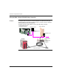
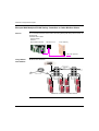
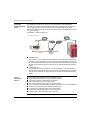
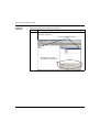
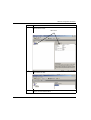
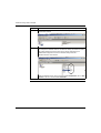
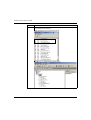
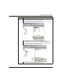
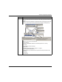
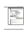
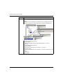
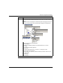
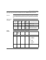
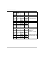
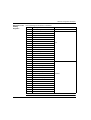
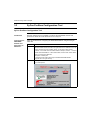
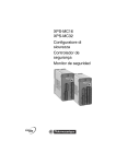
PROFIBUS / MODBUS
GATEWAY
Application Note for
Communication
between Premium CPU &
XPS-MC Safety Controllers
33003105.02
eng
2
Table of Contents
About the Book . . . . . . . . . . . . . . . . . . . . . . . . . . . . . . . . . . . . . . . 5
Chapter 1
Introduction to the LUFP7 Gateway . . . . . . . . . . . . . . . . . . . . . . 7
Introduction to the LUFP7 Gateway . . . . . . . . . . . . . . . . . . . . . . . . . . . . . . . . . . . 7
Chapter 2
Hardware Configuration Examples . . . . . . . . . . . . . . . . . . . . . . . 9
Introduction . . . . . . . . . . . . . . . . . . . . . . . . . . . . . . . . . . . . . . . . . . . . . . . . . . . . . . 9
Example With a Single XPS-MC Safety Controller . . . . . . . . . . . . . . . . . . . . . . . 10
Example With Multiple XPS-MC Safety Controllers or
Other Modbus Slaves . . . . . . . . . . . . . . . . . . . . . . . . . . . . . . . . . . . . . . . . . . . . . 12
Chapter 3
3.1
3.2
3.3
3.4
3.5
Software Configuration Examples . . . . . . . . . . . . . . . . . . . . . . 15
Introduction . . . . . . . . . . . . . . . . . . . . . . . . . . . . . . . . . . . . . . . . . . . . . . . . . . . . .
Introduction of the Software Configuration Example . . . . . . . . . . . . . . . . . . . . . .
Example With Premium PLC and an XPS-MC Safety Controller . . . . . . . . . . . .
LUFP7 Gateway with the ABC LUFP Configuration Tool . . . . . . . . . . . . . . . . . .
Introduction . . . . . . . . . . . . . . . . . . . . . . . . . . . . . . . . . . . . . . . . . . . . . . . . . . . . .
LUFP7 Gateway With the ABC LUFP Configuration Tool. . . . . . . . . . . . . . . . . .
Overview of the Information Available From the
XPS-MC Safety Controller. . . . . . . . . . . . . . . . . . . . . . . . . . . . . . . . . . . . . . . . . .
SyCon Profibus Configuration Tool . . . . . . . . . . . . . . . . . . . . . . . . . . . . . . . . . . .
SyCon Profibus Configuration Tool . . . . . . . . . . . . . . . . . . . . . . . . . . . . . . . . . . .
Configure Unity Pro (Profibus Master) . . . . . . . . . . . . . . . . . . . . . . . . . . . . . . . .
Configure Unity Pro (Profibus Master) . . . . . . . . . . . . . . . . . . . . . . . . . . . . . . . .
Steps to Check When Not Running. . . . . . . . . . . . . . . . . . . . . . . . . . . . . . . . . . .
Steps to Check When Not Running. . . . . . . . . . . . . . . . . . . . . . . . . . . . . . . . . . .
15
17
17
18
18
19
33
36
36
44
44
48
48
3
4
About the Book
At a Glance
Document Scope
This documentation briefly describes the setup for communication between a
Profibus Master DP and an XPS-MC Modbus slave. For further information about
the gateway refer to the "LUFP7 Telemecanique Gateway Profibus-DP / Modbus
RTU User’s manual"
Validity Note
In spite of all care taken over the writing of this document, Schneider Electric SA
does not give any guarantees in the realtion to the information contained in it, and
may not be held liable for any errors, nor for any damage which might result from its
use or its application.
The characteristics and operation of the products and additives presented in this
document may change at any time. The description is in no way contractually
binding.
Related
Documents
User Comments
02/2005
Title of Documentation
Reference Number
LUFP7 Telemecanique Gateway Profibus-DP / Modbus RTU
User’s manual
-
We welcome your comments about this document. You can reach us by e-mail at
[email protected]
5
About the Book
6
02/2005
Introduction to the LUFP7
Gateway
1
Introduction to the LUFP7 Gateway
Overview
The LUFP7 gateway allows a master located on a Profibus-DP network to
communicate with slaves on a Modbus RTU network. This is a generic protocol
converter operating in a way which is transparent to the user.
This gateway allows the user to interface many products marketed by Schneider
Electric with a Profibus-DP network. These include TeSys U motor starters, Altivar
driver and the XPS-MC Safety Controllers.
This document concerns the communication between a Premium CPU and an
XPS-MC Safety Controller. The present documentation only briefly describes the
setup for communication between a Profibus Master DP and an XPS-MC Modbus
slave. For further information about the gateway refer to the "LUFP7 Telemecanique
Gateway Profibus-DP / Modbus RTU User’s manual".
Terminology
The term "RTU", refers to the Modbus RTU communication protocol and can be
omitted. As a result, the term "Modbus" will refer to the Modbus RTU communication
protocol.
As is still the case with all communication systems, the terms "input" and "output"
are somewhat ambiguous. To avoid any confusion, we use a single convention
throughout this document. So the notions of "input" and "output" are always as seen
from the PLC, or the Profibus-DP master.
Hence, an "output" is a command signal sent to a Modbus slave, whereas an "input"
is a monitoring signal generated the same Modbus slave.
Because we are only concerned with the XPS-MC signals in this document, we have
only "inputs" from the Modbus slave.
02/2005
7
Introduction to the LUFP7 Gateway
8
02/2005
Hardware Configuration
Examples
2
Introduction
Overview
This chapter contains the hardware configuration examples.
What's in this
Chapter?
This chapter contains the following topics:
02/2005
Topic
Page
Example With a Single XPS-MC Safety Controller
10
Example With Multiple XPS-MC Safety Controllers or Other Modbus Slaves
12
9
Hardware Configuration Examples
Example With a Single XPS-MC Safety Controller
Example
The diagram below shows the connections between a Profibus-DP master (for
example, Premium TSX with the Profibus Interface TSX PBY 100) and a Modbus
slave (XPS-MC) via the LUFP7 gateway.
Example Premium Profibus Master and one XPS-MC Safety Controller:
Profibus Master Premium
with Profibus Interface
LUFP7 gateway
490 NAE 911 00
490 NAD 911 03
490 NAD 911 04
XPS-MC
10
1. Powersupply
24 V=
2. Configuration
3. Modbus
02/2005
Hardware Configuration Examples
Parts used
The connection between Premium and gateway requires the following parts:
l Cable: TSX PB SCA 100
l NAD 911 04 used to join between slaves (i.e. not at the end of line, therefor no
line termination).
l NAD 911 03 used at the end of the line, therefor requires line termination.
Profibus Connector NAD 911 0x
02/2005
1
Incoming A cable.
2
Outgoing A cable (absent in the case of the 490 NAD 911 03 connector).
3
Cable collar; the cable sheath must be uninsulated under the collar.
11
Hardware Configuration Examples
Example With Multiple XPS-MC Safety Controllers or Other Modbus Slaves
General
The connection between the Premium and the gateway will always be the same, as
shown here.
Premium with LUFP7
Profibus
ProfibusMaster
Master
Premium
Premium
withProfibus
ProfibusInterface
Interface
with
490 NAE 911 00
LUFP7 Gateway
Profibus DP upstream
Using Modbus
Hub LU9GC03
Modbus Hub LU9GC03
Maximum of 8 XPS-MC Modbus slaves
12
02/2005
Hardware Configuration Examples
Using Bus
topology with
VW3 A8 306 TF3
drop boxes
VW3 A8 306 TF3 drop boxes
Line termination
Line termination
Line terminator
02/2005
For the previous networks shown, the following line terminator is always needed for
terminating the line: VW3 A8 306 RC
13
Hardware Configuration Examples
Using Bus
topology with tap
boxes
This topology is similar to the previous one, except that it uses TSXSCA62
subscriber connectors and/or TSXCA50 subscriber connectors. We recommend
using a VW3 A8 306 connection cable and the TSXCSA•00 Modbus cables.
Connect the RJ45 connector on the VW3 A8 306 cable to the Modbus connector on
the LUFP7 gateway.
TSXSCA62 / TSXCA50 tap boxes
VW3 A8 306
l TSXSCA62 box:
This passive box has a printed circuit fitted with screw terminals and allows the
connection of two subscribers to the bus two female 15 point SUB-D connectors.
It includes the line termination when the connector is located at the end. It is fitted
with two screw terminals for the connection of two double twisted pair Modbus
cables.
l TSXSCA50 box:
This passive box allows a Modbus unit to be connected to a screw terminal. It
includes the line termination when the connector is located at the end. It is fitted
with two screw terminals for the connection of two double twisted pair Modbus
cables.
Wiring
recommendations
14
General wiring recommendations for the Modbus network:
Use a shielded cable with 2 pairs of twisted conductors.
Connect the reference potentials to one another.
The maximum length of line is 1000 meters.
The maximum length of drop line / tap-off is 20 meters.
Do not connect more than 9 stations to a bus (8 slaves and one LUFP7 gateway).
Keep the bus away from power cables (at least 30 cm).
If crossings are necessary make then at right angles.
Connect the cable shielding to the earth on each unit.
Adapt the line at both ends using a line terminator.
l
l
l
l
l
l
l
l
l
02/2005
Software Configuration Examples
3
Introduction
Overview
This chapter contains the software configuration examples.
What's in this
Chapter?
This chapter contains the following sections:
02/2005
Section
Topic
Page
3.1
Introduction of the Software Configuration Example
17
3.2
LUFP7 Gateway with the ABC LUFP Configuration Tool
18
3.3
SyCon Profibus Configuration Tool
36
3.4
Configure Unity Pro (Profibus Master)
44
3.5
Steps to Check When Not Running
48
15
Software Configuration Examples
16
02/2005
Software Configuration Examples
3.1
Introduction of the Software Configuration
Example
Example With Premium PLC and an XPS-MC Safety Controller
Introduction
The example shows a configuration with following devices (see also Example With
a Single XPS-MC Safety Controller, p. 10), the values shown in the pictures are the
defaults with which the example was running. You should not change these values
unless neccessary.
Hardware devices:
Premium PLC as PROFIBUS DP MASTER
LUFP7 as gateway for PROFIBUS SLAVE / MODBUS MASTER
XPS-MC as MODBUS SLAVE
Cable, connectors and line termination
l
l
l
l
Software devices:
l ABC LUFP configuration tool (See LUFP7 Gateway with the ABC LUFP
Configuration Tool, p. 18)
l SyCon Profibus configuration tool and the relevant GSD (General Slave Data) Files (See SyCon Profibus Configuration Tool, p. 36)
l Unity Pro XL application software (See Configure Unity Pro (Profibus Master),
p. 44)
l XPSMCWIN configuration tool for the XPS-MC Safety Controllers
Note: In the following sections it is assumed, that the hardware is connected and
power is on.
02/2005
17
Software Configuration Examples
3.2
LUFP7 Gateway with the ABC LUFP Configuration
Tool
Introduction
Overview
This section describes the steps required for the ABC LUFP configuration tool.
What's in this
Section?
This section contains the following topics:
18
Topic
Page
LUFP7 Gateway With the ABC LUFP Configuration Tool
19
Overview of the Information Available From the XPS-MC Safety Controller
33
02/2005
Software Configuration Examples
LUFP7 Gateway With the ABC LUFP Configuration Tool
Introduction
With this tool (can be downloaded from Internet: www.hms.se/abc_lufp.shtml), the
gateway between the Profibus and the Modbus networks is configured. In this
example, the Profibus Master is a Schneider Premium PLC and the Modbus Slave
an XPS-MC Safety Controller. The following steps detail the configuration process:
Step
02/2005
Action
1
Define the networks (See Define the Networks, p. 20)
2
Add commands (See Add Commands, p. 23)
3
Save and download to the gateway (See Save and Download to the Gateway,
p. 32)
19
Software Configuration Examples
Define the
Networks
Steps to be followed for defining the networks:
Step
1
Action
Start the ABC-LUFP-Configurator and select the PROFIBUS fieldbus.
ABC-LUFP configurator:
Select the PROFIBUS fieldbus
The information about the
selected items is shown here
20
02/2005
Software Configuration Examples
Step
2
Action
Check the values for part ABC.
Default values for ABC:
ABC values
02/2005
3
Insert the XPS-MC Safety Controller in the MODBUS sub-network.
Slave Address for ABC:
4
By clicking once on New Node, it is possible for it to be renamed. For this
example, we have called it MC32.
21
Software Configuration Examples
Step
Action
5
In the right-hand window, enter the slave address. e.g. 32.
Update slave address:
6
Click on Sub-Network to enter the relevant values in the right-hand window. In
this example the standard values for the XPS-MC Safety Controller are shown.
The values entered must be the same as the values configured by the
XPSMCWIN configuration tool for the XPS-MC Safety Controller.
Standard values for sub-network:
Hint: For additional slaves, click on the left window Sub-Network, then on SubNetwork in the menu bar and select Add Node!
22
02/2005
Software Configuration Examples
Add Commands
This example shows how to add all available commands. Infact, to get all the
information it is only necessary to add the holding registers, because the information
from the inputs (command 01 = Read Coil Status) and outputs (command 02 = Read
Input Status) are included. For normal monitoring only, "command 03 = Read
Holding Registers" is sufficient (refer to step 8 and 9). To gain a better
understanding, this procedure shows how to add all three commands.
Step
1
Action
Click in the left window on MC32.
Open MC32 in the menu bar and select Add Command.
Add command:
See also Overview of the Information Available From the XPS-MC Safety
Controller, p. 33.
02/2005
23
Software Configuration Examples
Step
2
Action
Now double click on the command 01, 02 and 03. (Only the first three commands
are supported by the XPS-MC.)
Select command 01, 02, 03 by double clicking:
Result: Now you should see the following screen:
24
02/2005
Software Configuration Examples
Step
3
Action
For the configuration of the query, click on Query (the query is the same for all
three commands, i.e. read coil, read input and holding).
When you select an item in the right part of the screen, a summary about the
selected item is shown in the lower part of the screen.
For the configuration of the reponse, click on Reponse (the response is the
same for all three commands , i.e read coil, read input and holding).
When you select an item in the right part of the screen, a summary about the
selected item is shown in the lower part of the screen.
If the data is correct for your application leave it as it is.
02/2005
25
Software Configuration Examples
Step
4
Action
Configuration for: Read Coil Status / Query.
Click on the left-hand side on the relevant function and you get the windows on
the right.
Result: All values are displayed in hexadecimal (when changing the values you
can enter in decimal and it will be automatically changed into hexadecimal).
1
2
3
5
4
There are 5 sub menus of the query:
1. Slave address
Default is the Modbus address of the MC32 (decimal 32 = 20 hex)
2. Function
Command 01 (read coil status)
3. Starting address
Refer to table Addresses and Commands, p. 33 column 1
4. Number of points
Refer to table Addresses and Commands, p. 33 column 3 (decimal 40 = 28
hex)
5. Checksum
Do not alter
26
02/2005
Software Configuration Examples
Step
5
Action
Configuration for: Read Coil Status / Response.
Click on the left-hand side on the relevant function and you get the windows on
the right.
Result: All values are displayed in hexadecimal (when changing the values you
can enter in decimal and it will be automatically changed into hexadecimal).
1
2
5
4
3
There are 5 sub menus of the response:
1. Slave address
Default is the Modbus address of the MC32 (decimal 32 = 20 hex)
2. Function
Command 01 (read coil status)!
3. Byte count
Number of bytes (see query): 40 bits / 8 = 5 bytes!
4. Date length is 5 bytes (see 3)
Data location is 2, because the first 2 bytes are used by the status of the
gateway
5. Checksum
Do not alter
02/2005
27
Software Configuration Examples
Step
6
Action
Configuration for: Read Input Status / Query.
Click on the left-hand side on the relevant function and you get the windows on
the right.
Result: All values are displayed in hexadecimal (when changing the values you
can enter in decimal and it will be automatically changed into hexadecimal).
1
2
5
4
3
There are 5 sub menus of the query:
1. Slave address
Default is the Modbus address of the MC32 (decimal 32 = 20 hex)
2. Function
Command 02 (read input status)
3. Starting address
Refer to table Addresses and Commands, p. 33 column 1
4. Number of points
Refer to table Addresses and Commands, p. 33 column 3 (decimal 40 = 28
hex)
5. Checksum
Do not alter
28
02/2005
Software Configuration Examples
Step
7
Action
Configuration for: Read Input Status / Response.
Click on the left-hand side on the relevant function and you get the windows on
the right.
Result: All values are displayed in hexadecimal (when changing the values you
can enter in decimal and it will be automatically changed into hexadecimal).
1
2
3
5
4
There are 5 sub menus of the response:
1. Slave address
Default is the Modbus address of the MC32 (decimal 32 = 20 hex)
2. Function
Command 02 (read input status)!
3. Byte count
Number of bytes (see query): 40 bits / 8 = 5 bytes!
4. Data length is 5 bytes (see 3)
Data location is 7, because "Read coil status" starts at 2 and needs 5 bytes
5. Checksum
Do not alter
02/2005
29
Software Configuration Examples
Step
8
Action
Configuration for: Holding Registers / Query.
Click on the left-hand side on the relevant function and you get the windows on
the right.
Result: All values are displayed in hexadecimal (when changing the values you
can enter in decimal and it will be automatically changed into hexadecimal).
1
2
Response
Query
3
5
4
There are 5 sub menus of the query:
1. Slave address
Default is the Modbus address of the MC32 (decimal 32 = 20 hex)
2. Function
Command 03 (holding registers)
3. Starting address
Refer to table Addresses and Commands, p. 33 column 1
4. Number of points
Refer to table Addresses and Commands, p. 33 column 3 (decimal 14 = 0E
hex)
5. Checksum
Do not alter
30
02/2005
Software Configuration Examples
Step
9
Action
Configuration for: Holding Registers / Response.
Click on the left-hand side on the relevant function and you get the windows on
the right.
Result: All values are displayed in hexadecimal (when changing the values you
can enter in decimal and it will be automatically changed into hexadecimal).
1
2
Read Holding Register
Response
3
5
4
There are 5 sub menus of the response:
1. Slave address
Default is the Modbus address of the MC32 (decimal 32 = 20 hex)
2. Function
Command 03 (holding registers)!
3. Byte count
Number of bytes (see query): 14 words * 2 = 28 bytes (1C hex)
4. Data length is 5 bytes (see 3)
Data location is 12 (0C hex), because "Read input status" starts at 7 and
needs 5 bytes
5. Checksum
Do not alter
02/2005
31
Software Configuration Examples
Save and
Download to the
Gateway
Result
32
Steps to be followed for saving and downloading to the gateway:
Step
Action
1
Save the configuration.
2
Connect the PC with the gateway.
For the connection you need a Modbus cable with RJ45 connectors or you can
use a Ethernet cable, because of the similar pin assignment and a RS232 /
RS485 converter with a SUB D 9 - female / RJ45 - female connector.
3
Download the configuration. A name for the configuration is recommended.
The gateway is now configured.
You can now proceed with the steps in the SyCon Profibus configuartion tool (See
SyCon Profibus Configuration Tool, p. 36).
02/2005
Software Configuration Examples
Overview of the Information Available From the XPS-MC Safety Controller
Overview
The following describes the information transmitted by the XPS-MC over Modbus.
In the HOLDING Register (command 03) you can see in addition to the diagnostics,
also the information for the INPUTS (command 01) and the OUTPUTS (command
02).
Addresses and
Commands
Addresses and commands 01 read coil, 02 read input, 03 holding - registers:
Holding
Registers
Addresses
Addresses
(hexadecimal) (decimal)
Size of
Data
Supported
Modbus
Function
Results for Usage
0100-0127
256-295
40 bits
01 (0x01)
(read coil)
8 bit output data /32 bit input data
(0 = OFF, 1 = ON)
0200-0227
512-551
40 bits
02 (0x02)
(read input)
32 bit input data /32 bit output data
(0 = OFF, 1 = ON)
1000-100D
4096-4109
14 words
03 (0x03)
(holding
registers)
Information and errors
for details refer to next table
Information about the 14 words of the holding registers:
Word
Address
(hexadecimal)
Word
Address
(decimal)
High Byte
Low Byte
Details
Status
Mode
bit4: 0 = XPSMC32
bit4: 1= XPSMC16
bit6: 1 = config OK
Status
bit0: 1 = RUN
bit1: 1 = CONF
bit3: 1 = INT Error
bit4: 1 = EXT Error
bit5: 1 = STOP
Hardware and Configuation
02/2005
1000
4096
1001
4097
Mode
reserved
33
Software Configuration Examples
Word
Address
(hexadecimal)
Word
Address
(decimal)
High Byte
Low Byte
1002
4098
Input data
(Input 1-8)
Input data
(Input 9-16)
1003
4099
Input data
(Input 17-24)
Input data
(Input 25-32)
1004
4100
not used
(always 0)
Output data
(Output 1-8)
1005
4101
Input error
(Input 1-8)
Input error
(Input 9-16)
1006
4102
Input error
(Input 17-24)
Input error
(Input 25-32)
1007
4103
not used
(always 0)
Output error
(Output 1-8)
Details
I/O-Data
Bit
1 = corresponding in/output on
I/O-Errors
Bit
1 = corresponding in/output error
Diagnostic Hints (DH)
34
1008
4104
(DH 1)
Index High
(DH 1)
Index Low
1009
4105
not used
(always 0)
(DH 1)
Message
100A
4106
(DH 2)
Index High
(DH 2)
Index Low
100B
4107
not used
(always 0)
(DH 2)
Message
100C
4108
(DH 3)
Index High
(DH 3)
Index Low
100D
4109
not used
(always 0)
(DH 3)
Message
Index *
number of devices
Message
Diagnostic Hint
Significtaion: see next table
* The index gives the order of the
devices in the configuration. The
indexes for all devices can be
found in the protocol of the
configuration.
02/2005
Software Configuration Examples
Diagnostic in the
Holding
Registers
Error meassage and indication of XPS-MC:
Code No. Meaning
Status
0
OK, no message
Operation
1
Short-circuit between inputs
2
Hardware defect
3
Muting error
4
Override timeout
5
Timeout error
6
Over travel exceeded
7
Short-circuit
8
Muting lamp defect
9
Cam switch mechanism defect
10
Press safety valve defect
11
External voltage defect
12
Output will not switch ON
Error
13
14
15
16
Reset button blocked
17
Timeout
18
Incomplete opening
19
Start interlock active
20
Open circuit
21
Delay time running
22
Check locking device
23
Check valve
24
Unexpected muting signal
Indication
25
26
27
28
29
30
31
02/2005
35
Software Configuration Examples
3.3
SyCon Profibus Configuration Tool
SyCon Profibus Configuration Tool
Introduction
With this software tool it is possible to configure the PROFIBUS network and
generate an ASCII file for the Premium PLC in Unity Pro.
Configuring the
PROFIBUS
Network and
Generating an
ASCII File
Steps to be followed for configuring the PROFIBUS Network and generating an
ASCII file:
36
Step
Action
1
For the slave configuration, the GSD file is needed. In our example, it is the file
TELE071F.GSD. This file must be in the right folder for the GSD files. It is in the
location where SyCon was installed. There, you will find a folder named
"Fieldbus". In this folder there are folders called "CANopen, Interbus..." and also
a folder called "PROFIBUS". In the Profibus folder, there is folder called "GSD",
where you will find the GSD files.
Example for a folder path:
"c:\programms\schneider electric\SyCon\Fieldbus\PROFIBUS\GSD".
Copy this file in the right directory.
2
Start SyCon.
SyCon Start picture
02/2005
Software Configuration Examples
Step
3
02/2005
Action
Select PROFIBUS as the fieldbus system.
37
Software Configuration Examples
Step
4
Action
In our example we have a Schneider Premium PLC as PROFIBUS MASTER
with the device TSX PBY 100. The other two devices shown in the picture are
other Schneider products. In this screeen you can also change the description
and the address of the master.
Select the master:
Result: After inserting the master the window should look like this:
Here you can change the
address and the description by
double clicking on Master1
38
02/2005
Software Configuration Examples
Step
5
Action
Now insert the slave. For this example, it is the gateway.
Slave Gateway:
Slave:
02/2005
39
Software Configuration Examples
Step
6
Action
By double clicking on SLAVE1, you can change the name and the address. (For
this example, we use 73.)
Configure slave window:
Enter 73 as station address
7
40
Using the rotaty switches, adjust the gateway to have the same address.
Gateway rotary switches:
02/2005
Software Configuration Examples
Step
8
Action
To configure the slave window you have to know how much data is to be
transfered.
To find this information, start the ABC LUFP configuation tool and press the
icon to open the Modbus Memory window.
Modbus Memory window in the ABC LUFP configuation tool:
grey data are Status
of the gateway
The Modbus Memory window has two areas:
In Area
Out Area
So you need an input and output in SyCon.
l
l
9
10
02/2005
Calculate the amount of date to be transfered:
for the output you need 2 bytes (grey data) = 1 word
for the input you need:
1. Status: 2 bytes = 1 word (grey data)
2. Read Coil status: 40 bits = 5 bytes = 2.5 words
3. Read input status: 40 bits = 5 bytes = 2.5 words
4. Read holding registers: 14 words
(see also Addresses and Commands, p. 33)
Conclusion: 1 word (2 bytes) for output, 20 words (40 bytes) for input
(because of the lack of a 20 word input you have to split it in a 16 word and a
4 word module, or the any other combination to get 20 words in total).
l
l
Switch back to the SyCon configuration tool.
41
Software Configuration Examples
Step
42
Action
11
In the Slave Configuration window select OUTPUT: 2 Byte ( 1 word) for the
output.
Area out 1 word:
12
In the Slave Configuration window select INPUT: 32 Byte (16 word) for the
input.
Area in 16 words:
13
In the Slave Configuration window select INPUT: 8 Byte ( 4 word) for the input.
Area in 4 words:
02/2005
Software Configuration Examples
Step
Action
14
Save the configuration.
15
Export this configuration for Unity.
Note: Only 8 characters are allowed for the filename.
Result
02/2005
The file for the fieldbus master is now ready. You can proceed with Configure Unity
Pro (Profibus Master), p. 44.
43
Software Configuration Examples
3.4
Configure Unity Pro (Profibus Master)
Configure Unity Pro (Profibus Master)
Introduction
To run the Profibus you need a Master. In this example we take the Schneider
Premium with the Profibus Interface TSX PBY 100.
Configure
Unity Pro
Steps to be followed for configuring Unity Pro:
44
Step
Action
1
Start Unity Pro.
2
Define a PLC configuration (example shown below).
PLC configuration in Unity Pro:
3
To import the SyCon file double click on the PBY 100 (see PLC configuration in
step 2).
Result: The PBY 100 configuration window appears.
02/2005
Software Configuration Examples
Step
02/2005
Action
4
Import the CNF file by clicking Load CNF.
Import SyCon file in Unity Pro:
5
Select the SyCon file.
45
Software Configuration Examples
Step
6
Action
Adapt the IW / IQ size.
No. of IW/QW >=
Total No. of IW/QW.
Diagnostic 6
Note:
The diagnostic length can be set between 6 and 24 bytes.
IW/QW can only be set to 32, 64, 128 and 242.
Result: Adapted sizes
7
46
Generate the file for the Premium PLC and download it.
02/2005
Software Configuration Examples
Step
8
Action
Run the PLC.
Result: PLC and network should be in RUN state.
Unity configurator window without an error (no red fields):
Front plate of PBY 100:
These two LEDs must be green
This LED must blinking green
Result
02/2005
Your system is now working.
If you encounter any problems proceed with Steps to Check When Not Running,
p. 48.
47
Software Configuration Examples
3.5
Steps to Check When Not Running
Steps to Check When Not Running
Check
Steps to be followed when the system is not running:
Step
1
Action
Check that the XPS-MC Safety Controller has the right configuration,
specifically the right MODBUS address. In our example, the XPS-MC address
is 32!
Correct MODBUS configuration in XPS-MC Safety Controller and in the ABC
LUFP:
SECUFLEX
48
ABC LUFP
02/2005
Software Configuration Examples
Step
2
Action
Check the Profibus slave address in SyCon and the number of words. The
number of bytes must be equal, or lower in the SyCon than configured in the
ABC configuration tool. Here in the ABC tool 40 Input Bytes and 2 Output Bytes
are provided = > in SyCon 40 / 2 = 20 input words and 2 / 2 = 1 output word in
maximum.
SyCon / ABC check:
Number of bytes must be equal
3
Check that the SyCon address and hardware address of the gateway are equal.
In our example, the gateway address is 73!
Hardware address and SyCon address:
put in 73 as station address
02/2005
49
Software Configuration Examples
50
02/2005