1
cover_7503A2008.10.296:21PM페이지 1
RD-7503
RD-7503(A)2008.11.41:45PM페이지 2
ENGLISH
IMPORTANT SAFETY INSTRUCTIONS
1. Read these instructions.
2. Keep these instructions.
3. Heed all warnings.
4. Follow all instructions.
5. Do not use this apparatus near water.
6. Clean only with dry cloth.
7. Do not block any ventilation openings.
Install in accordance with the manufacturer’s instructions.
8. Do not install near any heat sources such as radiators,
heat registers, stoves, or other apparatus (including
amplifiers) that produce heat.
9. Do not defeat the safety purpose of the polarized or
grounding-type plug. A polarized plug has two blades
with one wider than the other.
A grounding type plug has two blades and a third
grounding prong. The wide blade or the third prong are
provided for your safety. If the provided plug does not fit
into your outlet, consult an electrician for replacement of
the obsolete outlet.
10. Protect the power cord from being walked on or pinched
particularly at plugs, convenience receptacles, and the
point where they exit from the apparatus.
11. Only use attachments accessories specified by the
manufacturer.
12. Use only with the cart, stand, tripod, bracket, or table
specified by the manufacturer, or sold with the
apparatus.
When a cart is used, use caution when moving the
cart/apparatus combination to avoid injury from tip-over.
PORTABLE CART WARNING
13. Unplug this apparatus during lightning storms or when
unused for long periods of time.
14. Refer all servicing to qualified service personnel.
Servicing is required when the apparatus has been
damaged in any way, such as power-supply cord or
plug is damaged, liquid has been spilled or objects have
fallen into the apparatus, the apparatus have been
exposed to rain or moisture, does not operate normally,
or has been dropped.
2
RD-7503(A)2008.11.41:45PM페이지 3
Introduction
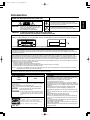
This symbol is intended to alert the user to the presence of
uninsulated "dangerous voltage" within the product's
enclosure that may be of sufficient magnitude to constitute
a risk of electric shock to persons.
: TO REDUCE THE RISK OF ELECTRIC
SHOCK, DO NOT REMOVE COVER (OR
BACK). NO USER-SERVICEABLE PARTS
INSIDE. REFER SERVICING TO
QUALIFIED SERVICE PERSONNEL.
CAUTION
This symbol is intended to alert the user to the presence of
important operating and maintenance (servicing)
instructions in the literature accompanying the appliance.
WARNING : TO REDUCE THE RISK OF FIRE OR ELECTRIC SHOCK,
DO NOT EXPOSE THIS APPLIANCE TO RAIN OR MOISTURE.
Caution regarding installation
Note : For heat dispersal, do not install this unit in a confined space such as a bookcase or similar enclosure.
Do not block ventilation openings or stack other equipment on the top.
Note to CATV System Installer :
This reminder is provided to call the CATV system installer’s attention to Article 820-40 of the NEC that provides guidelines for proper
grounding and, in particular, specifies that the cable ground shall be connected to the grounding system of the building, as close to the point
of cable entry as practical.
FCC INFORMATION
This equipment has been tested and found to comply with the limits for a Class B digital device, pursuant to Part 15 of the FCC Rules. These
limits are designed to provide reasonable protection against harmful interference in a residential installation. This equipment generates, uses and
can radiate radio frequency energy and, if not installed and used in accordance with the instructions, may cause harmful interference to radio
communications. However, there is no guarantee that interference will not occur in a particular installation. If this equipment does cause harmful
interference to radio or television reception, which can be determined by turning the equipment off and on, the user is encouraged to try to correct
the interference by one or more of the following measures:
�Reorient or relocate the receiving antenna.
�Increase the separation between the equipment and receiver.
�Connect the equipment into an outlet on a circuit different from that to which the receiver is connected.
�Consult the dealer or an experienced radio/TV technician for help.
Caution : Any changes or modifications in construction of this device which are not expressly approved by the party responsible for compliance
could void the user’s authority to operate the equipment.
This Class B digital apparatus complies with Canadian ICES-003.
Cet appareil numérique de la Classe B est conforme à la norme NMB-003 du Canada.
FOR YOUR SAFETY
U.S.A
CANADA
CAUTION
• Leave a space around the unit for sufficient ventilation.
• Avoid installation in extremely hot or cold locations, or in an area
that is exposed to direct sunlight or heating equipment.
• Keep the unit free from moisture, water, and dust.
• Do not let foreign objects in the unit.
• The ventilation should not be impeded by covering the ventilation
openings with items, such as newspapers, table-cloths, curtains, etc.
• No naked flame sources, such as lighted candles, should be placed
on the unit.
• Please be care the environmental aspects of battery disposal.
• The unit shall not be exposed to dripping or splashing for use.
• No objects filled with liquids, such as vases, shall be placed on the
unit.
• Do not let insecticides, benzene, and thinner come in contact with
the set.
• Never disassemble or modify the unit in any way.
■Notes on the AC power cord and the wall outlet.
• The unit is not disconnected from the AC power source(mains) as
long as it is connected to the wall outlet, even if the unit has been
turned off.
• To completely disconnect this product from the mains, disconnect
the plug from the wall socket outlet.
• When setting up this product, make sure that the AC outlet you are
using is easily acceptable.
• Disconnect the plug from the wall outlet when not using the unit for
long periods of time.
120 V
Units shipped to the U.S.A and CANADA are designed for operation
on 120 V AC only.
Safety precaution with use of a polarized AC plug.
However, some products may be supplied with a nonpolarized plug.
CAUTION
: To prevent electric shock, match wide blade of
plug to wide slot, fully insert.
ATTENTION
: Pour éviter chocs électriques, introduire la lame
la plus large de la fiche dans la borne
correspondante de la prise et pousser jusqu’ au
fond.
ENERGY STAR� is a U.S. registered mark. As an
ENERGY STAR� Partner, Sherwood has
determined that this product meets the ENERGY
STAR� guidelines for energy efficiency.
3
ENGLISH
READ THIS BEFORE OPERATING YOUR UNIT
RD-7503(A)2008.11.41:45PM페이지 4
ENGLISH
CONTENTS
• IMPORTANT SAFETY INSTRUCTIONS . . . . . . . . . . . . . . . . . . . . . . . . . . . . . . . . . . . . . . . . . . . . . . . . . . . . . . 2
• Introduction
READ THIS BEFORE OPERATING YOUR UNIT . . . . . . . . . . . . . . . . . . . . . . . . . . . . . . . . . . . . . . . . . . . . 3
• System Connections . . . . . . . . . . . . . . . . . . . . . . . . . . . . . . . . . . . . . . . . . . . . . . . . . . . . . . . . . . . . . . . . . . . . 5
• Front Panel Controls . . . . . . . . . . . . . . . . . . . . . . . . . . . . . . . . . . . . . . . . . . . . . . . . . . . . . . . . . . . . . . . . . . . 13
• Universal Remote Controls . . . . . . . . . . . . . . . . . . . . . . . . . . . . . . . . . . . . . . . . . . . . . . . . . . . . . . . . . . . . . . 15
OPERATING COMPONENTS WITH REMOTE CONTROL . . . . . . . . . . . . . . . . . . . . . . . . . . . . . . . . . . . 17
REMOTE CONTROL OPERATION RANGE . . . . . . . . . . . . . . . . . . . . . . . . . . . . . . . . . . . . . . . . . . . . . . . 17
LOADING BATTERIES . . . . . . . . . . . . . . . . . . . . . . . . . . . . . . . . . . . . . . . . . . . . . . . . . . . . . . . . . . . . . . . 17
USING FUNCTIONS OF REMOTE CONTROL . . . . . . . . . . . . . . . . . . . . . . . . . . . . . . . . . . . . . . . . . . . . . 18
• Operations
LISTENING TO A PROGRAM SOURCE . . . . . . . . . . . . . . . . . . . . . . . . . . . . . . . . . . . . . . . . . . . . . . . . . . 21
SURROUND SOUND . . . . . . . . . . . . . . . . . . . . . . . . . . . . . . . . . . . . . . . . . . . . . . . . . . . . . . . . . . . . . . . . 23
ENJOYING SURROUND SOUND . . . . . . . . . . . . . . . . . . . . . . . . . . . . . . . . . . . . . . . . . . . . . . . . . . . . . . . 25
LISTENING TO RADIO BROADCASTS . . . . . . . . . . . . . . . . . . . . . . . . . . . . . . . . . . . . . . . . . . . . . . . . . . 29
LISTENING TO SIRIUS SATELLITE RADIO . . . . . . . . . . . . . . . . . . . . . . . . . . . . . . . . . . . . . . . . . . . . . . . 31
(SIRIUS Satellite Radio (only for North America))
RECORDING . . . . . . . . . . . . . . . . . . . . . . . . . . . . . . . . . . . . . . . . . . . . . . . . . . . . . . . . . . . . . . . . . . . . . . . 35
DIGITAL AUDIO RECORDING WITH MD RECORDER . . . . . . . . . . . . . . . . . . . . . . . . . . . . . . . . . . . . . . 36
OTHER FUNCTIONS . . . . . . . . . . . . . . . . . . . . . . . . . . . . . . . . . . . . . . . . . . . . . . . . . . . . . . . . . . . . . . . . . 37
ROOM 2 SOURCE PLAYBACK . . . . . . . . . . . . . . . . . . . . . . . . . . . . . . . . . . . . . . . . . . . . . . . . . . . . . . . . 38
• OSD Menu Settings . . . . . . . . . . . . . . . . . . . . . . . . . . . . . . . . . . . . . . . . . . . . . . . . . . . . . . . . . . . . . . . . . . . . 39
SETTING THE SYSTEM SETUP . . . . . . . . . . . . . . . . . . . . . . . . . . . . . . . . . . . . . . . . . . . . . . . . . . . . . . . . 41
SETTING THE INPUT SETUP . . . . . . . . . . . . . . . . . . . . . . . . . . . . . . . . . . . . . . . . . . . . . . . . . . . . . . . . . . 45
SETTING THE SPEAKER / ROOM EQ SETUP . . . . . . . . . . . . . . . . . . . . . . . . . . . . . . . . . . . . . . . . . . . . 51
SETTING THE CH LEVEL SETUP . . . . . . . . . . . . . . . . . . . . . . . . . . . . . . . . . . . . . . . . . . . . . . . . . . . . . . 57
SETTING THE SOUND PARAMETER . . . . . . . . . . . . . . . . . . . . . . . . . . . . . . . . . . . . . . . . . . . . . . . . . . . 59
SETTING THE MULTI ROOM SETUP . . . . . . . . . . . . . . . . . . . . . . . . . . . . . . . . . . . . . . . . . . . . . . . . . . . 61
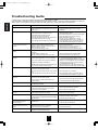
• Troubleshooting Guide . . . . . . . . . . . . . . . . . . . . . . . . . . . . . . . . . . . . . . . . . . . . . . . . . . . . . . . . . . . . . . . . . 62
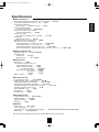
• Specifications . . . . . . . . . . . . . . . . . . . . . . . . . . . . . . . . . . . . . . . . . . . . . . . . . . . . . . . . . . . . . . . . . . . . . . . . . 63
• Setup Code Table . . . . . . . . . . . . . . . . . . . . . . . . . . . . . . . . . . . . . . . . . . . . . . . . . . . . . . . . . . . . . . . . . . . . . . 64
4
RD-7503(A)2008.11.41:45PM페이지 5
• Please be certain that this unit is unplugged from the AC outlet before making any connections.
• Since different components often have different terminal names, carefully read the operating instructions of the component
connected.
• Be sure to observe the color coding when connecting audio, video and speaker cords.
• Make connections firmly and correctly. If not, it can cause loss of sound, noise or damage to the receiver.
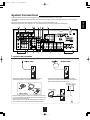
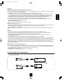
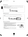
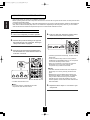
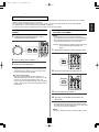
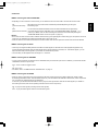
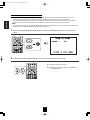
1. CONNECTING ANTENNAS
• A 75Ω outdoor FM antenna may be used to further
improve the reception. Disconnect the indoor antenna
before replacing it with the outdoor one.
• Change the position of the FM indoor antenna until you
get the best reception of your favorite FM stations.
• Place the AM loop antenna as far as possible from the receiver, TV set, speaker cords and the AC input cord and set it to a
direction for the best reception.
• If the reception is poor with the AM loop antenna, an AM outdoor antenna can be used in place of the AM loop antenna.
5
ENGLISH
System Connections
RD-7503(A)2008.11.41:45PM페이지 6
ENGLISH
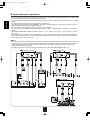
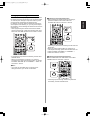
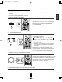
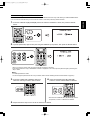
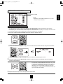
2. CONNECTING VIDEO COMPONENTS
• The jacks of VIDEO 1 may also be connected to a DVD recorder or other digital video recording component. For details, refer
to the operating instructions of the component to be connected.
• The jacks of VIDEO 2/VIDEO 3 can also be connected to an additional video component such as a cable TV tuner or satellite
system.
• Connect the jacks of VIDEO 3 to the video component in the same way.
• There are three types of video jacks (COMPONENT, S-VIDEO, (composite) VIDEO) for analog video connections and the
HDMI connectors for digital video and audio connections.
Connect them to the corresponding video jacks according to their capability.
• For your reference, the excellence in picture quality is as follows : "HDMI” > "COMPONENT" > "S-VIDEO" > "(composite)
VIDEO" .
• When making COMPONENT VIDEO connections, connect "Y" to "Y", "PB/CB" to "CB"(or "B-Y", "PB") and "PR/CR" to "CR"(or
"R-Y", "PR").
• When recording video program sources through VIDEO 1 OUT jack or viewing video program sources through MONITOR
OUT or ROOM 2 OUT jack, you must use the same type of video jacks that you did connect to video playback components
such as DVD player, cable TV tuner, etc.
�Notes :
• You can connect Apple iPod to this receiver via Sherwood iPod dock. If Sherwood iPod dock is connected to DIGI LINK-i jack
for system control, you should connect its video and audio jacks to the "VIDEO 2" jacks of this receiver. Because, when you
control your iPod with the unit's remote control, the VIDEO 2/iPod is automatically selected as an input source and the
corresponding operation is performed.
• The OSD menu and the momentary OSD can be displayed via the (composite) VIDEO MONITOR OUT only.
6
RD-7503(A)2008.11.41:45PM페이지 7
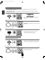
Continued
• You can connect the source component (DVD player, etc.) to the display component (TV, projector, etc.) through this receiver
with using a commercially available HDMI cord.
• The HDMI connection can carry uncompressed digital video signals and digital audio signals.
• The HDMI video stream signals (video signals) are theoretically compatible with DVI-D. When connecting to a TV monitor,
etc., equipped with DVI-D connector, it is possible to connect using a commercially available HDMI-DVI converter cord.
Since the HDMI-to-DVI connection cannot carry any audio signals, you should make audio connections to play the audio
signals on the component equipped with DVI-D connector. (For details, refer to the operating instructions of its.)
• If you connect the HDMI INs to your video components, it is easier to do so following the default settings.
• If your HDMI connection is different from the default setting, you should assign the HDMI INs you used with the "When
selecting the HDMI ASSIGN" procedure on page 46.
• The default settings are as follows :
HDMI 1 : VIDEO 1, HDMI 2 : VIDEO 2/iPod, HDMI 3 : VIDEO 3
�Copyright protection system
• This unit supports HDCP (High-bandwidth Digital Contents Protection), technology to protect copyright of digital video signals
against illegal duplication. HDCP must also be supported on the components connected to this unit.
• This unit is HDMI Ver. 1.3 compatible.
• HDMI, the HDMI logo and High-Definition Multimedia Interface are trademarks or registered trademarks of HDMI licensing
LLC.
�Notes :
• For stable signal transfer, we recommend using HDMI cords that are a maximum of 5 meters in length.
• Among the components that support HDMI, some components can control other components via the HDMI connector.
However, this unit cannot be controlled by another component via the HDMI connector.
• The audio signals from the HDMI connector (including the sampling frequency and bit length) may be limited by the
component that is connected.
• The video signals will not be output properly if a component incompatible with HDCP is connected.
• If the resolutions of the video signals which are output from the MONITOR OUTs and your monitor TV are not matched, the
picture is not clear, natural or displayed. In this case, change the setting of the resolution on the source component (DVD
player, etc.) to one which the monitor TV can handle. (For details, refer to the operating instructions of the source component.)
• When you want to enjoy only the picture on your TV, not the sound, you should set the HDMI AUDIO OUT to OFF not to
output the digital audio signal from the HDMI MONITOR OUT of this receiver. (For details, refer to "When selecting the HDMI
AUDIO OUT" on page 42.)
�Component video input default settings: (*2)
• If you connect the COMPONENT VIDEO INs to your video components, it is easier to do so following the default settings.
• If your component video connections are different from the default setting, you should assign the COMPONENT VIDEO INs
you used with the "When selecting the VIDEO ASSIGN" procedure on page 46.
• The default settings are as follows:
COMPONENT IN 1 : VIDEO 1, COMPONENT IN 2 : VIDEO 2/iPod
3. CONNECTING AUDIO COMPONENTS
• When recording audio signals, connect the AUDIO IN/OUT jacks of 'VIDEO 1" to audio recording equipment such as a tape
deck, an MD recorder, etc.
7
ENGLISH
�HDMI (High Definition Multimedia Interface) connection : (*1)
RD-7503(A)2008.11.41:45PM페이지 8
ENGLISH
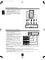
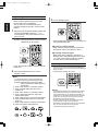
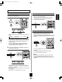
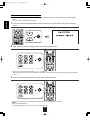
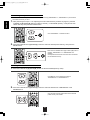
4. CONNECTING EXTERNAL INS
• Use these jacks to connect the corresponding outputs
of a DVD player or external decoder, etc. that has 6, 7
or 8 channel analog audio outputs.
• In case of 6 or 7 channel outputs, do not connect both
of the SURROUND BACK L and R inputs or the
SURROUND BACK R input of this unit. (For details,
refer to the operating instructions of the component to
be connected.)
5. CONNECTING DIGITAL INS AND OUT
• The OPTICAL and the COAXIAL DIGITAL OUTs of the
components that are connected to this unit can be
connected to these DIGITAL INs.
• A digital input should be connected to the components
such as a CD player, DVD player, etc. capable of
outputting DTS Digital Surround, Dolby Digital or PCM
format digital signals, etc.
• If the component with OPTICAL IN jack is connected to
the OPTICAL OUT jack of this unit, you can record the
high quality sound of CDs, etc. without degradation.
• For details, refer to the operating instructions of the
component connected.
• When making the COAXIAL DIGITAL connection, be
sure to use a 75 Ω COAXIAL cord, not a conventional
AUDIO cord.
• All of the commercially available optical fiber cords
cannot be used for the equipment. If there is an optical
fiber cord which cannot be connected to your equipment,
consult your dealer or nearest service organization.
�Notes :
• Be sure to make either a OPTICAL or a COAXIAL DIGITAL connection on each component. (You don’t need to do both.)
• Depending on the digital audio signal format input into the HDMI IN connector, some digital signals cannot be output from
the OPTICAL OUT jack.
�Digital input default settings
• If you connect the DIGITAL INs to your components, it is easier to do so following the default settings.
• If your DIGITAL connections are different from default settings, you should assign the DIGITAL INs you used with the
"When selecting the AUDIO ASSIGN" procedure on page 46.
• The default settings are as follows :
OPTICAL IN 1:VIDEO 1, OPTICAL IN 2:VIDEO 2/iPod, COAXIAL IN 1 : CD, COAXIAL IN 2 : F. AUX
8
RD-7503(A)2008.11.41:45PM페이지 9
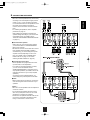
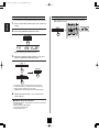
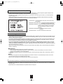
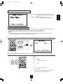
6. CONNECTING SPEAKERS
ENGLISH
• Be sure to connect speakers firmly and correctly
according to the channel(left and right) and the
polarity (+ and -). If the connections are faulty,
no sound will be heard from the speakers, and if
the polarity of the speaker connection is
incorrect, the sound will be unnatural and lack
bass.
• For installing the speakers, refer to "Speaker
placement" on page 10.
• After installing the speakers, first adjust the
speaker settings according to your environment
and speaker layout. (For details, refer to
"SETTING THE SPEAKER /ROOM EQ SETUP"
on page 51.)
�Surround back speakers
• When using only one surround back speaker,
you should connect it to SURROUND BACK/
MULTI LEFT channel.
• Because this receiver cannot drive the surround
back speakers and the ROOM 2 speakers
simultaneously, you should assign their power
amplifier correctly depending on how to use
them. (For details, refer to "CONNECTING
ROOM 2 OUTS" on page 11 and "When
selecting the AMP ASSIGN" on page 41.)
�Front Bi-Amp Connections.
• Some speakers are equipped with two sets of
input terminals, for bi-amplification.
• If no other surround back speakers are used,
you can connect the FRONT and the
SURROUND BACK/MULTI channels to the biamp-capable speakers. (For details, refer to the
operating instructions of your bi-amp-capable
speakers.)
• To drive the bi-amp-capable speakers, you
should assign the power amplifier to "BI-AMP".
�Note :
• Before making bi-amp connections, remove the
short-circuiting bars from the terminals of your
speakers.
Caution :
• Be sure to use the speakers with the impedance
of 6 ohms or above.
• Do not let the bare speaker wires touch each
other or any metal part of this unit. This could
damage this unit and/or the speakers.
• Never touch the speaker terminals while the AC
input cord is connected to the wall AC outlet.
Doing so could result in electric shocks.
9
RD-7503(A)2008.11.41:45PM페이지 10
Continued
ENGLISH
�Connecting speaker wire
1. Strip away approx. 10 mm
(3/8 inch) of wire insulation,
then twist the wire ends
tight.
2. Lossen by turning the
speaker terminal counterclockwise.
3. Insert the bare part of the
wire.
4. Tighten by turning it
clockwise.
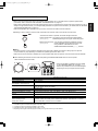
Speaker placement
Ideal speaker placement varies depending on the size of
your room and the wall coverings, etc. The typical example
of speaker placement and recommendations are as follows :
■Front left and right speakers and center speaker
• Place the front speakers with their front surfaces as flush
with TV or monitor screen as possible.
• Place the center speaker between the front left and right
speakers and no further from the listening position than
the front speakers.
• Place each speaker so that sound is aimed at the location
of the listener’s ears when at the main listening position.
■Surround left and right speakers
• Place the surround speakers approximately 1 meter (40
inches) above the ear level of a seated listener on the
direct left and right of them or slightly behind.
■Surround back left and right speakers
• Place the surround back speakers at the back facing the
front at a narrower distance than front speakers.
• When using a single surround back speaker, place it at the
rear center facing the front at a slightly higher position (0
to 20 cm ) than the surround speakers.
• We recommend installing the surround back speaker(s) at
a slightly downward facing angle. This effectively prevents
the surround back channel signals from reflecting off the
TV or screen at the front center, resulting in interference
and making the sense of movement from the front to the
back less sharp.
■Subwoofer
• The subwoofer reproduces powerful deep bass sounds.
Place a subwoofer anywhere in the front as desired.
1. TV or Screen
2. Front left speaker
3. Subwoofer
4. Center speaker
5. Front right speaker
6. Surround left speaker
�Notes :
�When using a conventional TV, to avoid interference with
the TV picture, use only magnetically shielded front
left and right and center speakers.
�To obtain the best surround effects, the speakers except
the subwoofer should be full range speakers.
7.
CONNECTING SUBWOOFER PRE OUT
• To emphasize the deep bass sounds, connect a powered
subwoofer.
10
7. Surround right speaker
8. Surround back left speaker
9. Surround back right speaker
10. Surround center speaker
11. Listening position
RD-7503(A)2008.11.41:45PM페이지 11
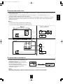
• ROOM 2 playback feature allows you to play a different program source in another room as well as one source in the main
room at the same time.
• For ROOM 2 playback, connect the ROOM 2 OUT jacks to the amplifier, TV, etc. installed in another room, or
connect the ROOM 2 speaker terminals to the speakers.
• Because this receiver cannot drive the surround back speakers and the ROOM 2 speakers simultaneously, you should
assign their power amplifier correctly depending on how to use them. (For details, refer to "When selecting the AMP
ASSIGN" on page 41.)
�Notes :
• To minimize hum or noise, use high quality connection cords.
• You cannot use the digital audio signal for ROOM 2 playback.
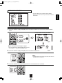
9. CONNECTING DC TRIGGER OUT
• Connect a component to DC TRIGGER OUT jack
that allows DC 12V to turn on when a specific
input source is selected.
• For details, refer to the operating instructions of
the components to be connected.
• To link DC TRIGGER OUT with a specific input
source, refer to "When selecting the DC
TRIGGER" on page 47.
�Notes :
• This output voltage (12V d.c., 100mA) is for (status) control only, it is not sufficient for drive capability.
• When making DC TRIGGER connection, you should use the stereo mini cord, not a mono mini cord.
11
ENGLISH
8. CONNECTING ROOM 2 OUTS
RD-7503(A)2008.11.41:45PM페이지 12
ENGLISH
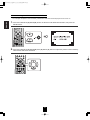
10. CONNECTING FOR SYSTEM CONTROL
• Connect this jack to the DIGI LINK-i jack of Sherwood
iPod dock that allows you to control the iPod with the
unit's remote control.
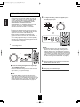
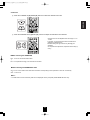
11. CONNECTING SIRIUS CONNECTOR (only for North America)
SiriusConnect Home Tuner
• Connect the SIRIUS connector to the Sirius Connect
Home Tuner kit (sold separately).
• Position the Home Tuner antenna near a south-facing
window to receive the best signal.
When making connections, also refer to the operating
instructions of the SiriusConnect Home Tuner.
• To listen to SIRIUS Satellite Radio, refer to "SIRIUS
Satellite Radio (only for North America)" on page 31.
To a wall AC
outlet
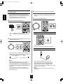
�Positioning the antenna
• For a consistent satellite signal, the antenna must be
positioned correctly. Use the following map to determine
which area you are in and position the antenna
accordingly.
• Area 1 : Point the antenna toward the sky in the east,
notrtheast, or southeast, either through a window or
out side.
• Area 2 : Point the antenna toward the sky in the north
or northeast, either through a window or outside.
• Area 3 : Point the antenna toward the sky in the north
or northwest, either through a window or outside.
• Area 4 : Point the antenna toward the sky in the west,
northwest, or southwest, either through a window or
outside.
• Area 5 : Put the antenna outside and point it straight
up. The antenna cannot be used indoors.
12. AC INPUT CORD
• Plug this cord into a wall AC outlet.
12
RD-7503(A)2008.11.41:45PM페이지 13
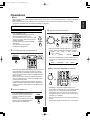
ENGLISH
Front Panel Controls
1. POWER switch
2. POWER ON/STANDBY button
3. STANDBY indicator
4. INPUT SELECTOR knob
5. BAND button
6. EXTERNAL IN button
7. SURROUND MODE/CONTROL DOWN(▼) button
8. STEREO/CONTROL UP(▲) button
9. MASTER VOLUME CONTROL knob
10. MULTI CONTROL knob(◀/▶)
11. HEADPHONE jack
12. SPEAKER button
13. ROOM 2 button
14. CHANNEL LEVEL button
15. SETUP button
16. MEMORY/ENTER button
17. TUNING UP(+)/DOWN(-) buttons
18. PRESET UP(+)/DOWN(-) buttons
19. AUDIO ASSIGN button
20. SETUP MIC jack
For details, see next page.
21. FRONT AUX IN jack
For details, see next page.
22. Bluetooth IN connector
For details, see next page.
23. SPEAKER indicator
24. REMOTE SENSOR
25. FLUORESCENT DISPLAY
For details, see next page.
�FLUORESCENT DISPLAY
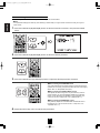
1. Input, frequency, volume level, operating information, etc.
2. Surround mode indicators
3. AUTO indicator
4. DIGITAL input indicator
5. DIRECT indicator
6. Preset number, sleep time display
13
7. PRESET indicator
8. MEMORY indicator
9. SLEEP indicator
10. ROOM 2 indicator
11. TUNED indicator
12. STEREO indicator
RD-7503(A)2008.11.41:45PM페이지 14
ENGLISH
� SETUP MIC JACK
• To use Auto Setup function, connect the supplied microphone to the SETUP MIC jack.(For details, refer to "When
selecting the AUTO SETUP" on page 51.)
�Notes:
• Because the microphone for Auto Setup is designed for use with this receiver, do not use a microphone other than
the one supplied with this receiver.
• After you have completed the auto setup procedure, disconnect the microphone.
Microphone
� FRONT AUX IN JACK
• The FRONT AUX IN jack can be connected to additional audio components such as an MP3 player, etc.
� Note :
• When connecting this jack to an MP3 player, etc., you should use the stereo mini cord, not a mono mini cord.
�Bluetooth IN CONNECTOR
• If the Bluetooth IN connector is connected to Sherwood Audio Receiver
BT-R7(sold separately) with Bluetooth wireless technology, you can enjoy
music wirelessly with a music player featuring Bluetooth wireless
technology such as MP3 player, mobile phone, etc..
(For information on Sherwood Audio Receiver BT-R7, contact your dealer.)
• The Bluetooth word mark and logos are registered trademarks owned by
Bluetooth SIG, Inc. and any use of such marks by Sherwood Corporation is
under license. Other trademarks and trade names are those of their
respective owners.
� Notes:
• For safe operation, turn the power off before connecting or disconnecting
the Audio Receiver BT-R7.
• When not using the Bluetooth IN connector, cover it with the supplied cap.
14
RD-7503(A)2008.11.41:45PM페이지 15
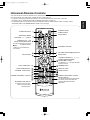
This universal remote control can operate not only this receiver but also most popular brands of audio and video components
such as iPod docks, TVs, DVD players, satellite receivers, cable boxes, etc.
• To operate 5 components other than this receiver, you should enter the setup code for each component.
(For details, refer to “USING FUNCTIONS OF REMOTE CONTROL” on page 18.)
• The numbered buttons on the remote control have different functions in different device modes. For details, refer to
"FUNCTION TABLE of the NUMBERED BUTTONS" on the next page.
STANDBY button
STEREO button
POWER ON button
SLEEP button
SURROUND MODE
UP/DOWN (�/�) buttons
NUMERIC (0~9, +10)/
INPUT SELECTOR buttons
To select the desired input source
of TUNER~VIDEO 3
� Note :
• "VIDEO 4" is not available for
this receiver.
EXTERNAL IN button
VOLUME UP/DOWN(▲/▼) buttons
SETUP button
MUTE button
CURSOR CONTROL(△,▽,◁,▷),
ENTER</SEARCH MODE,
SELECT◀▶> buttons
The function in "< >" are regional option
for Notrh America
TEST TONE button
DIMMER button
AUDIO ASSIGN button
CHANNEL LEVEL button
DISPLAY button
ROOM 2 button
TUNING UP/DOWN(+/-) buttons
PRESET UP/DOWN(+/-) buttons
DEVICE buttons
To operate the desired component with
this remote control, first select the
corresponding DEVICE button.
MACRO(M1~M3) buttons
SET LED
To operate a macro function,
press the corresponding
MACRO button.
15
ENGLISH
Universal Remote Controls
RD-7503(A)2008.11.41:45PM페이지 16
�FUNCTION TABLE of the NUMBERED BUTTONS.
ENGLISH
(for iPod Dock)
(for VCR)
(for TV)
(for DVD Player)
(for satellite
receiver)
(for cable box)
POWER ON
POWER ON
POWER ON
POWER ON
POWER ON
STANDBY
(POWER OFF)
STANDBY
(POWER OFF)
STANDBY
(POWER OFF)
STANDBY
(POWER OFF)
STANDBY
(POWER OFF)
NUMERIC
NUMERIC
NUMERIC
NUMERIC
NUMERIC
PLAY LIST
UP/DOWN(</>)
DOCK MODE
CHANNEL
CHANNEL
ALBUM
UP/DOWN(∨/∧) UP/DOWN(∨/∧) UP/DOWN(∨/∧)
CHANNEL
CHANNEL
UP/DOWN(∨/∧) UP/DOWN(∨/∧)
VOLUME
VOLUME
UP/DOWN(▲/▼) UP/DOWN(▲/▼)
VOLUME
VOLUME
UP/DOWN(▲/▼) UP/DOWN(▲/▼)
SETUP
MUTE
MUTE
UP/DOWN(▲/▼)
CURSOR
CONTROL
ENTER
ENTER
MENU
MENU
MUTE
MUTE
INPUT
SELECTOR
INPUT
SELECTOR
RETURN
REPEAT
INPUT
SELECTOR
INPUT
SELECTOR
DISPLAY
RANDOM
RECORD
PAUSE
STOP
PLAY/PAUSE
PAUSE
STOP
PLAY
PLAY
REWIND (
)/
FAST FORWARD (
REVERSE SERARCH(
FORWARD SEARCH(
)
REVERSE SKIP(
FORWARD SKIP (
REVERSE SKIP ( ) /
FORWARD SKIP ( )
)/
)
)/
)
AUDIO
SUBTITLE
�Notes :
• Some functions for each component may not be available or may work differently.
• Depending on other kinds of components that are available for each DEVICE button, some functions may not be available or
may work differently, too.
• For details about functions, refer to the operating instructions of each component.
16
RD-7503(A)2008.11.41:45PM페이지 17
1. Enter the setup code for each
REMOTE CONTROL OPERATION RANGE
• Use the remote control within a range of about 7 meters
(23 feet) and angles of up to 30 degrees aiming at the
remote sensor.
component other
than this receiver. For details, refer to "Entering
a setup code" on page 18.
2. Turn on the component you want to operate.
3. Press the DEVICE button on the
remote control
corresponding to the component you wish to
operate.
4. Aim the remote control at the REMOTE
SENSOR of the component you wish to control
and press the button corresponding to the
operation you want.
• In such a case that some components do not have the
REMOTE SENSOR which receives the remote signals,
this remote control cannot operate them.
LOADING BATTERIES
�When the remote control does not operate, the old batteries should be replaced. In this case, load new batteries within several
minutes after removing old batteries.
�If the batteries are removed or have been exhausted for a longer period of time, memorized contents will be cleared. Should
this happen, you should memorize them again.
1. Remove the cover.
2. Load two batteries ("AAA" size, 1.5V) matching
the polarity.
• Remove the batteries when they are not used for a long
time.
• Do not use the rechargeable batteries (Ni-Cd type).
• Be sure to use alkaline batteries.
17
ENGLISH
OPERATING COMPONENTS WITH REMOTE CONTROL
RD-7503(A)2008.11.41:45PM페이지 18
ENGLISH
USING FUNCTIONS OF REMOTE CONTROL
• This remote control can control up to 6 different components.
• Before operating audio and video components other than this receiver with using this remote control, the setup code for each
component should be entered.
• For system remote control operation, "000" was stored previously in the memory of the device button "DOCK" for Sherwood iPod
dock, "DVD" for Sherwood DVD player and "TV" for Sherwood TV respectively as its factory setup code. So, you don’t need to
enter its code for each Sherwood component except in such a case that its code does not work.
Entering a setup code
1. Turn on the component you want to operate.
4. Enter a 3 digit code, aiming the remote control
at the remote sensor on the component.
Example: When entering "001".
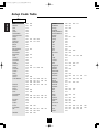
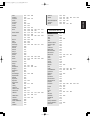
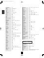
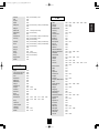
2. Find the setup codes according to the type and
the brand name of your component, referring to
"Setup Code Table" on page 62.
3. Press and hold down both the ENTER button
and the desired one of the DEVICE buttons for
more than 1 seconds.
• If entering is performed successfully, the SET LED will
flicker twice.
• To be sure that the setup code is correct, press the
POWER ON (or STANDBY) button. If your component
is turned off, the setup code is correct.
• When your component is not turned off, repeat the
above steps 2 to 4, trying each code for your
component until you find one that works.
�Notes:
• If the SET LED did not flicker twice, then repeat the
above steps 3 to 4 and try entering the same code
again.
• Manufacturers may use different setup codes for the
same product category. For that reason, it is important
that you check to see if the code you have entered
operates as many controls as possible. If only a few
functions operate, check to see if another code will work
with more buttons.
• The SET LED will flicker once.
�Note :
5. Repeat the above steps 1 to 4 for each of your
• The "AVR" button is unavailable for the audio
components other than this receiver.
components.
18
RD-7503(A)2008.11.41:45PM페이지 19
This remote control may be programmed to operate either
the AUDIO volume punch-through or the TV volume and/or
TV channel punch-through in conjunction with any of the
six components controlled by this remote control.
For example, since this receiver will likely be used as the
sound system while watching TV, you may want to adjust
this receiver’s volume although this remote control is set to
control the TV.
• When programming this remote control for the AUDIO
volume punch-through, press and hold down both "AVR"
button and "VOLUME ▲" button for more than 1 second.
�Removing a punch-through function
• When removing the AUDIO volume punch-through,
press and hold down both "AVR" button and
"VOLUME ▼" button for more than 1 second.
• If removing is performed successfully, the SET LED will
flicker twice.
• When you want to remove either TV volume or TV
channel punch-through, press and hold down both "TV"
button and either "VOLUME ▼" or "CHANNEL ∨"
button for more than 1 second.
• If programming is performed successfully, the SET LED
will flicker twice.
• When you want either TV volume or TV channel
punch-through, press and hold down both "TV" button
and either "VOLUME ▲" or "CHANNEL ∧" button for
more than 1 second.
�Removing all punch-through functions
Press and hold down both "AVR" button and "AUDIO
ASSIGN" button for more than 1 second.
�Note :
• If you use one of AUDIO and TV volume punchthrough functions, you cannot use the other.
• If removing all punch-through functions is performed
successfully, the LED will flicker twice.
19
ENGLISH
Using a punch-through function
RD-7503(A)2008.11.41:45PM페이지 20
ENGLISH
Programming a macro function
3. Press "ENTER" button.
• The macro function enables you to program a
series of button operations(up to 10) on this
remote control into a single button.
• You can store up to three separate macro
command sequences into "M1", "M2" and "M3"
buttons.
1. Press and hold down both "ENTER" button and
one of three NUMERIC buttons ("1" ~ "3")
corresponding to "M1"~"M3" buttons for more
than 1 second.
Example: When programming a series of button
operations into "M1" button.
• If the programming is performed successfully, the
SET LED will flicker twice.
�To remove a macro program
• When removing a macro program, perform the
above steps 1 and 3, but ignore the step 2.
�To change a macro program
• When a new macro program is stored into a
MACRO button with performing the above steps
1 to 3, the previous macro program is cleared
from the memory of the MACRO button.
Operating a macro function
• If the macro mode is entered, the SET LED will
flicker once.
• Aim the remote control at the REMOTE SENSORs of
the components to be controlled and press the MACRO
button you want.
Example: When pressing "M1" button.
2. Press the operation buttons you want to
program in order.
�Note :
You should press the corresponding DEVICE
buttons before pressing each operation button.
Example: When playing a DVD on the DVD
player connected to VIDEO 3 jacks of
this receiver.
①. Press "AVR" button to control this receiver.
②. Press "POWER ON" button to turn this
receiver on.
③. Press "AVR" button to control this receiver.
④. Press "VIDEO 3(8)" button to select the
desired input source.
⑤. Press "DVD" button to control the DVD player.
⑥. Press "POWER ON" button to turn the DVD
player on.
⑦. Press "DVD" button to control the DVD player.
⑧. Press "▶" button to start playback.
�Notes:
• The codes programmed into a MACRO button will be
transmitted at an interval of 0.5 seconds. However,
some components may not be able to complete one
operation in 0.5 seconds and may miss the next code.
In this case, the macro function cannot control the
corresponding components correctly.
• Be sure to use the remote control within the remote
control operation range of the components.
• Depending on the operation status of the components,
etc., the macro function cannot control the
corresponding components correctly.
20
RD-7503(A)2008.11.41:45PM페이지 21
�Notes:
• Before operating this receiver with the supplied remote control, refer to "Universal Remote Controls" on page 15 for details
about operation.
• Before operating this receiver, first set this unit as desired for optimum performance, doing the OSD menu setting
procedures. (For details, refer to "OSD Menu Settings" on page 39.)
LISTENING TO A PROGRAM SOURCE
3. Select the desired input source.
Before operation
• Enter the standby mode.
• The STANDBY indicator lights up amber.
This means that the receiver is not
disconnected from the AC mains and a small
amount of current is retained to support the
operation readiness.
• To switch the power off, push the POWER
switch again.
Then the power is cut off and the
STANDBY indicator goes off.
• Each time the INPUT SELECTOR knob on the front
panel is rotated, the input source changes as follows:
→TUNER ↔ CD ↔ TAPE ↔ F.AUX ↔ VIDEO 1 ←
1. In the standby mode, turn the power on.
(Frequency display)
→
BT ↔
VIDEO 3 ↔
V2/IPOD ←
• Each time the BAND button (or the TUNER button on
the remote control) is pressed, the band changes as
follows:
→ FM ST → FM MONO → AM → SIRIUS
�When selecting the EXTERNAL IN as desired,
• Each time the POWER ON/STANDBY button on the front
panel is pressed, the receiver is turned on to enter the
operating mode (the STANDBY indicator lights up blue)
or off to enter the standby mode(the STANDBY indicator
lights up amber).
• On the remote control, press the POWER ON button to
enter the operating mode or press the STANDBY button
to enter the standby mode.
• In the standby mode, if the INPUT SELECTOR knob is
rotated or the INPUT SELECTOR button is pressed, the
receiver is turned on automatically and the desired input
is selected.
• Depending on the power amplifier setting for the
surround back channels and the surround back speaker
setting, "EXT. IN" is displayed and 8(/7/6) separate
analog signals from the component connected to this
input pass through the volume circuits only and can be
heard from your speakers.
• Select the desired input source to cancel the external in
function.
• These analog signals can be heard only, not recorded.
2. Switch the speakers on.
• Then the SPEAKER indicator lights up
and the sound can be heard from the
speakers connected to the speaker
terminals.
• When using the headphones for private
listening, press the SPEAKER button
again to switch the speakers off.
21
ENGLISH
Operations
RD-7503(A)2008.11.41:45PM페이지 22
ENGLISH
When CD, F.AUX, VIDEO 1~ 3 is selected as
an input source
6. Operate the selected component for playback.
• When playing back the program sources with surround
sound, refer to "ENJOYING SURROUND SOUND" on
page 25.
• If the AUDIO MODE is set to the mode other than
"DIGITAL" for the corresponding input source on the
INPUT SETUP menu, you cannot hear the sound from
the selected digital input. (For details, refer to
"SETTING THE INPUT SETUP" on page 45.)
7. Adjust the (overall) volume.
4. Press the AUDIO ASSIGN button.
Muting the sound
• "AUD ~ " is displayed for several seconds.
• "AUD ~ " disappears, press the AUDIO ASSIGN button
again.
5. Select the desired of the digital inputs connected
while displaying "AUD ~ ".
• "MUTE" flickers.
• To resume the previous sound level, press it again.
Listening with headphones
• Each time the MULTI CONTROL knob is rotated or the
CURSOR LEFT(◀)/RIGHT(▶) buttons are pressed, the
corresponding input is selected as follows :
→
OPT 1(Optical 1)
↔
OPT 2
←
→
---
↔ COX 2 ↔ COX 1(Coaxial 1) ←
(No assignment)
■Notes:
• When the selected digital input is not connected, the
digital input flickers and no sound will be heard.
• The selected digital input is automatically assigned to the
corresponding input source on the INPUT SETUP menu.
(For details, refer to "SETTING THE INPUT SETUP" on
page 45.)
• The sound from the component connected to the
selected digital input can be heard regardless of the
selected input source.
• Ensure that the SPEAKER button is set to off.
• When listening to a DTS or Dolby Digital program
source, if the headphones are plugged in and the
SPEAKER button is set to off, it enters the 2CH
downmix mode automatically. (For details, refer to "2CH
downmix mode" on page 26.)
■Note:
• Be careful not to set the volume too high when using
headphones.
22
RD-7503(A)2008.11.41:45PM페이지 23
SURROUND SOUND
Surround modes
■DTS Digital Surround
■Dolby Digital
DTS Digital Surround(also called simply DTS) supports up to
5.1 discrete channels and uses less compression for high
fidelity reproduction. Use it with DVDs and CDs bearing the
DTS logo.
Dolby Digital is the multi-channel digital signal format
developed by Dolby Laboratories. Discs bearing the Dolby
Digital logo includes the recording of up to 5.1 channels of
digital signals. This will put you right in the middle of the
action, just like being in a movie theater or concert hall.
■DTS-ES™ Discrete 6.1
This is a 6.1 channel discrete digital audio format adding a
surround back channel to the DTS digital surround sound. The
seven totally separate audio channels provide better spatial
imaging and 360 degrees sound localization, perfect for sounds
that pan across the surround channels. Use it with DVDs
bearing the DTS-ES logo, especially those with a DTS-ES
Discrete sound track.
■Dolby Digital EX
■DTS - ES™ Matrix 6.1
■Dolby Digital Plus
This is a 6.1 channel discrete digital audio format inserting a
surround back channel to the DTS digital surround sound
through matrix encoding. Use it with DVDs bearing the DTS-ES
logo.
Developed for use with HDTV, including the new video disc
formats Blu-ray and HD DVD, this is the latest multichannel
audio format from Dolby. It supports up to 7.1 channels with
48 kHz/24-bit sampling rate and signal resolution.
�DTS Neo : 6™ surround
■Dolby TrueHD
This mode expands 5.1-channel sources for 6.1/7.1 channel
playback. It's especially suited to Dolby Digital EX
soundtracks that include a matrix-encoded surround back
channel. The additional channel adds an extra dimension and
provides an enveloping surround sound experience, perfect
for rotating and fly-by sound effects.
DTS Neo : 6 is a matrix decoding technology for achieving 7.1
channel surround playback with 2 channel sources. It includes
"DTS Neo : 6 Cinema" suited for playing movies and "DTS
Neo : 6 Music" suited for playing music.
Designed to take full advantage of the additional storage
space offered by the new Blu-ray and HD DVD disc formats,
this new Dolby format offers up to 7.1 discrete channels of
lossless audio performance with 96 kHz/24 bit sampling rate
and signal resolution.
This receiver supports 7.1-channel sources up to 96 kHz.
�DTS 96/24
This is high resolution DTS with a 96 kHz sampling rate and
24 bit resolution, providing superior fidelity. Use it with DVDs
bearing the DTS 96/24 logo.
■Dolby Pro Logic IIx surround
This mode expands any 2-channel source for 7.1-channel
playback. It provides a very natural and seamless surround
sound experience that fully envelopes the listener. As well as
music and movies,video games can also benefit from the
dramatic spatial effects and vivid imaging. It includes "Dolby
Pro Logic IIx Movie" suited for playing movies, "Dolby Pro
Logic IIx Music" suited for playing music and "Dolby Pro Logic
IIx Game" suited for playing games.
�DTS-HD High Resolution Audio
Developed for use with HDTV, including the new video disc
formats Blu-ray and HD DVD, this is the latest multi-channel
audio format from DTS. It supports up to 7.1 channels with
96 kHz/24 bit sampling rate and signal resolution.
�DTS-HD Master Audio
Designed to take full advantage of the additional storage
space offered by the new Blu-ray and HD DVD disc formats,
this new DTS format offers up to 7.1 discrete channels of
uncompressed digital audio with 96 kHz/24 bit sampling rate
and signal resolution.
This receiver supports 7.1 channel sources up to 96 kHz.
■Dolby Pro Logic II surround
If you are not using any surround back speakers, Dolby Pro
Logic II surround will be used instead of Dolby Pro Logic IIx
surround. It incudes Dolby Pro Logic II Movie, Dolby Pro Logic
II Music and Dolby Pro Logic II Game like Dolby Pro Logic IIx
surround.
Manufactured under license under U.S. Patent #'s: 5,451,942;
5,956,674; 5,974,380; 5,978,762; 6,226,616; 6,487,535 & other U.S.
and worldwide patents issued & pending.
DTS is a registered trademark and the DTS logos, Symbol, DTS-HD
and DTS-HD Master Audio are trademarks of DTS, Inc.
ⓒ 1996-2007 DTS, Inc. All Rights Reserved.
Dolby and the double-D symbol are registered trademarks
of Dolby Laboratories.
23
ENGLISH
• This receiver incorporates a sophisticated Digital Signal Processor that allows you to create optimum sound quality and sound
atmosphere in your personal Home Theater.
ENGLISH
RD-7503(A)2008.11.41:45PM페이지 24
■Room
This mode provides the sound field of a house with a low
ceiling and hard walls for jazz music.
• The following modes apply conventional 2-channel signals
such as digital PCM or analog stereo signals to high
performance Digital Signal Processor to recreate sound
fields artificially. Select one of the 7 provided surround
modes according to the program source you want to play.
■Panorama
This mode provides a dynamic and broad sound space to
heighten the overall impact of the sound track.
■Theater
This mode provides the effect of being in a movie theater
when watching a play.
■Classic
This mode provides the acoustic effects of a large concert
hall for classical music.
■Hall
This mode provides the ambience of a concert hall for
classical music sources such as orchestral, chamber music
or an instrumental solo.
■Multi CH Stereo
This mode is designed for playing background music. The
front, surround and surround back channels create a stereo
image that encompasses the entire area.
■Stadium
This mode provides the expansive sound field to achieve the
true stadium effect when watching baseball or soccer games.
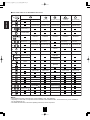
• When using the EXTERNAL INs to play back the sound from the additional multi-channel decoder for surround sound, you can
enjoy the corresponding surround sound, too. (For details, refer to the operating instructions of the component to be connected.)
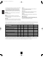
For your reference, the sound from each channel can be reproduced according to the surround modes as follows:
Modes
FRONT L/R
CENTER
SURROUND L/R
DTS-HD HIGH RESOLUTION AUDIO/MASTER AUDIO
Channels
�
�
�
SURROUND BACK L/R
�/—
SUBWOOFER
�
DTS, DTS 96/24
�
�
�
—
�
DTS ES DISCRETE/MATRIX
�
�
�
�
�
DTS NEO: 6 CINEMA/MUSIC
�
�
�
�
—(*)
DOLBY DIGITAL PLUS / DOLBY TRUEHD
�
�
�
�/—
�
DOLBY DIGITAL
�
�
�
—
�
DOLBY DIGITAL EX
�
�
�
�
�
DOLBY PRO LOGIC IIx MOVIE/MUSIC/GAME
�
�
�
�
�
DOLBY PRO LOGIC II MOVIE/MUSIC/GAME
�
�
�
—
�
MULTI PCM
�
�
�
�/—
�
Other Surrounds
�
�
�
�
—(*)
STEREO
�
—
—
—
—(*)
EXTERNAL IN
�
�
�
�
�
(*): Depending on the subwoofer setting, the sound from the subwoofer channel may be reproduced.
• Depending on the speaker settings and the number of the encoded channels, etc., the sound from the corresponding channels
cannot be reproduced.(For details, refer to "SETTING THE SPEAKER / ROOM EQ SETUP" on page 51.)
24
RD-7503(A)2008.11.41:45PM페이지 25
�Notes:
• Before surround playback, first perform the speaker setup procedure, etc. on the OSD menu for optimum performance.
(For details, refer to "SETTING THE SPEAKER / ROOM EQ SETUP" on page 51.)
• When playing digital signals from the Dolby Digital program source or selecting the surround mode such as Dolby Pro Logic II
/Dolby Pro Logic IIx Music mode, you can adjust their parameters for optimum surround effect. (For details, refer to "SETTING
THE SOUND PARAMETER" on page 59.)
• When the EXTERNAL IN is selected as an input source, the surround modes cannot be selected.
Depending on how to select a surround mode, select the auto surround mode or the manual surround mode.
• Each time this button is pressed, the mode changes as follows :
Auto surround mode : The optimum surround mode will be automatically
("AUTO" lights up.)
selected depending on the signal format being input.
Manual surround mode : You can select the desired of different surround
modes selectable for the signal being input with
("AUTO" goes off.)
using the MULTI CONTROL knob or the
SURROUND MODE UP/DOWN ( �/� ) buttons.
■Notes :
• Even when the auto surround mode is selected and the same type of digital signal format is being input, the optimum
surround mode may vary depending on whether the speaker type is set to "NO" or not.
• When the auto surround mode is selected, the surround modes other than the optimum surround mode cannot be selected.
■When selecting the manual surround mode with pressing the SURROUND MODE button on the front panel.
Select the desired surround mode.
• Each time the MULTI CONTROL knob is rotated
or the SURROUND MODE UP / DOWN (�/� )
buttons are pressed, the surround mode changes
depending on the input signal format as follows :
Signal format being input
Dolby Digital Plus sources
Dolby TrueHD sources
Dolby Digital EX 6.1 channel sources,
Dolby Digital 5.1 channel sources
Dolby Digital 2 channel sources
DTS-HD High Resolution Audio sources
DTS-HD Master Audio sources
DTS ES Discrete/Matrix 6.1 channel
sources
DTS sources, DTS 96/24 sources
PCM (multi-channel) sources*
96 kHz PCM (2 channel) sources
PCM (2 channel) sources,
Analog stereo sources
Selectable surround mode
DOLBY DIGITAL +
DOLBY TRUEHD
<DOLBY DIGITAL EX, DOLBY D + PLIIx MUSIC>, (DOLBY D + PLIIx MOVIE), DOLBY DIGITAL
<DOLBY PLIIx MOVIE, DOLBY PLIIx MUSIC, DOLBY PLIIx GAME>, [DOLBY PLII MOVIE,
DOLBY PLII MUSIC, DOLBY PLII GAME]
DTS-HD HI RES
DTS-HD MSTR
<corresponding DTS ES mode, DTS + PLIIx MUSIC>, (DTS + PLIIx MOVIE), DTS,
corresponding DTS mode, <DTS + NEO:6, DTS + PLIIx MUSIC>, (DTS + PLIIx MOVIE)
MULTI PCM, <DOLBY PLIIx MOVIE, DOLBY PLIIx MUSIC>
<DOLBY PLIIx MOVIE, DOLBY PLIIx MUSIC, DOLBY PLIIx GAME>, [DOLBY PLII MOVIE, DOLBY
PLII MUSIC, DOLBY PLII GAME], NEO:6 CINEMA, NEO:6 MUSIC, THEATER, HALL, STADIUM,
ROOM, PANORAMA, CLASSIC, MULTI-CH STEREO
• Depending on surround back speaker setting, some surround modes can be selected or not as follows:
< >: Possible only when surround back speaker is not set to "NO".
[ ] : Possible only when surround back speaker is set to "NO".
( ): Possible only when surround back speaker is set to " 2 CH".
* : Depending on the signal format being input, the Dolby Pro Logic IIx modes may not be selected.
25
ENGLISH
ENJOYING SURROUND SOUND
RD-7503(A)2008.11.41:45PM페이지 26
Continued
�To cancel the surround mode for stereo operation
ENGLISH
• Depending on the signal format which is being input, either
the stereo mode or the 2CH downmix mode is selected.
• To cancel either the stereo mode or the 2CH downmix
mode, select the surround mode with using the MULTI
CONTROL knob on the front panel or the SURROUND
MODE UP/DOWN (�/�) buttons on the remote control.
�2CH downmix mode
• This mode allows the multi-channel signals encoded in DTS or Dolby Digital format, etc. to be mixed down into 2 front
channels and to be reproduced through only two front speakers or through headphones.
• When the SPEAKER button is set to off to listen with headphones while playing the multi-channel digital signals from DTS or
Dolby Digital sources, etc., it will enter the 2CH downmix mode automatically.
Adjusting each channel level with test tone
• The volume level of each channel can be adjusted easily with the test tone function.
�Note : When the SPEAKER button is set to off, the test tone function does not work.
1. Enter the test tone mode.
• The test tone mode is displayed and will be heard from the
speaker of each channel for 2 seconds as follows:
→ FL → C →
FR →
SR
Front Left
SUB
Subwoofer
Center
Front Right
← SL ( ←
Surround Left
SB )
Surround Right
or ( SBL ←
SBR) ←
Surround Back Surr.Back Left Surr.Back Right
• When the speaker setting is "NO", the test tone of the
corresponding channel is not available.
• ( ) : Possible depending on whether the surround back
channel is set to "2 CH" or "1 CH".
2. At each channel, adjust the level as desired until the sound level of each speaker is heard to be equally loud.
• You can select the desired channel with pressing the
CONTROL UP/DOWN (▲/▼) buttons or the CURSOR
UP/DOWN (▲/▼) buttons.
3. Cancel the test tone function.
26
RD-7503(A)2008.11.41:45PM페이지 27
• After adjusting each channel level with test tone, adjust the channel levels either according to the program sources or to suit
your tastes.
• You can adjust the current channel levels as desired. These adjusted levels are just memorized into user’s memory
("CAL"), not into preset memory("REF 1", "REF 2").
1. Press the CHANNEL LEVEL button.
• Then the memory mode ("CAL", "REF 1", etc) is displayed
for several seconds.
• When the memory mode or channel level disappears,
press this button again.
2.
Select the desired channel.
• Each time these buttons are pressed, the corresponding
channel is selected as follows:
→ CAL (or REF 1, etc.) ↔ FL ← C ← FR ← SR ←
→ <LFE> ↔ SUB ↔ SL(↔SB) or (↔SBL ↔ SBR) ←
DTS LFE or Dolby Digital LFE
( ): Possible depending on whether the surround back channel is
set to "2 CH" or "1 CH".
< >: Possible only when the digital signals from Dolby Digital, DTS,
Dolby TrueHD or DTS HD program sources that include LFE
signal are input.
• Depending on the speaker settings("NO", etc.) and
surround mode, etc., some channels cannot be selected.
• When the SPEAKER button is set to off, only the Front
Left, Front Right(and LFE) channels can be selected.
3. Adjust the level of the selected channel as desired.
• The LFE level can be adjusted within the range of -10 ~ 0 dB
and other channel levels within the range of -15 ~ +15 dB.
• In general, we recommend the LFE level to be adjusted to
0 dB.(However, the recommended LFE level for some early
DTS software is -10 dB.) If the recommended levels seem
too high, lower the setting as necessary.
4. Repeat the above steps
2 and 3 to adjust each channel level.
27
ENGLISH
Adjusting the current channel level
RD-7503(A)2008.11.41:45PM페이지 28
Memorizing the adjusted channel levels
ENGLISH
• You can memorize the adjusted channel levels into preset memory("REF 1", "REF 2") and recall the
memorized whenever you want.
1. After performing the steps 1~4 in "Adjusting the current channel level" procedure on page 27, press the
(MEMORY/)ENTER button.
• The "1" of "REF 1" indication flickers for several
seconds.
2. Select the desired one of REF 1 and REF
2.
• If the preset memory disappears, perform the above
step 1 again.
3. Confirm your selection.
• The adjusted channel levels have now been
memorized into the selected memory.
Recalling the memorized channel levels
1. Press the CHANNEL LEVEL button.
• "CAL" (or "REF 1", etc.) is displayed for several seconds.
• If the memory mode disappears, press this button again.
2. Select the desired one of REF 1 and REF 2.
• Then the channel levels memorized into the selected
preset memory are recalled.
28
RD-7503(A)2008.11.41:45PM페이지 29
LISTENING TO RADIO BROADCASTS
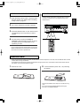
1. Select the desired band.
• Manual tuning is useful when you already know the
frequency of the desired station.
• After selecting the desired band, press the TUNING
UP(+)/DOWN(-) buttons repeatedly until the right
frequency has been reached.
Auto presetting
• Auto presetting function automatically searches for FM
stations only and store them in the memory.
• While listening to FM or AM radio broadcasts, press and
hold down the (MEMORY/)ENTER button for more than 2
seconds.
• Each time this button is pressed, the band changes as
follows :
→ FM ST → FM MONO → AM → SIRIUS
("ST" lights up) ("ST" goes off)
• When FM stereo broadcasts are poor because of weak
broadcast signals, select the FM mono mode to reduce
the noise, then FM broadcasts are reproduced in
monaural sound.
• To listen to SIRIUS Satellite Radio, select SIRIUS
mode. (For details, refer to "SIRIUS Satellite Radio
(only for North America)" on page 31.)
2. Press the TUNING UP(+)/DOWN(-) buttons for
more than 0.5 second.
• Then "AUTO MEM" flickers and this receiver starts auto
presetting.
• To stop auto presetting, press this button again.
• Up to 30 FM stations can be stored.
�Notes:
• FM stations of weak strength cannot be memorized.
• To memorize AM stations or weak stations, preform
"Manual presetting" procedure with using "Manual tuning"
operation.
• The tuner will now search until a station of sufficient
strength has been found. The display shows the tuned
frequency and "TUNE".
• If the station found is not the desired one, simply repeat
this operation.
• Weak stations are skipped during auto tuning.
29
ENGLISH
Manual tuning
Auto tuning
RD-7503(A)2008.11.41:45PM페이지 30
Manual presetting
Tuning to preset stations
ENGLISH
• You can store up to 30 preferred stations in the memory.
• After selecting the tuner as an input source, select the
desired preset number.
1. Tune in the desired station with auto or manual
tuning.
2. Press the (MEMORY/)ENTER button.
MEM
• "MEM" is flickering for several seconds.
3. Select the desired preset number (1~30) and
press the (MEMORY/)ENTER button.
• The station has now been stored in the memory.
• A stored frequency is erased from the memory by
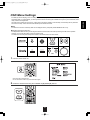
storing another frequency in its place.
• If "MEM" goes off, start again from the above step 2.
4. Repeat the above steps 1 to 3 to memorize
other stations.
�MEMORY BACKUP FUNCTION
The following items, set before the receiver is turned off,
are memorized.
• INPUT SELECTOR settings
• Surround mode settings
• Preset stations,etc.
30
RD-7503(A)2008.11.611:52AM페이지 31
SIRIUS Satellite Radio (only for North America)
�What SIRIUS Satellite Radio ?
Simpl The Best Radio on RadioTM with all your favorite entertainment including 100% commercial-free music, plus superior
sports coverage, uncensored talk and comedy, world-class entertainment, news, weather and more for your car, home or
office. For more information, visit sirius.com or siriuscanada.ca
Sirius is available in the US for subscribers with address in the continental US and is available in Canada for subscribers with
a Canadian address. Required subscription plus compatible SIRIUS tuner and antenna are required and sold saparately.
SIRIUS Programming is subject to change. Visit sirius.com for the most complete and up-to-date channel lineup and product
information.
"SIRIUS" and the SIRIUS dog logo and related marks are trademarks of Sirius Satellite Radio Inc. All rights reserved.
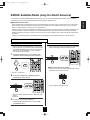
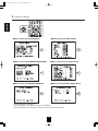
LISTENING TO SIRIUS SATELLITE RADIO
Signing up for SIRIUS Satellite Radio
Channel search
• Before using SIRIUS Satellite Radio, you must first sign
up for an account. You will need a major credit card and
your SIRIUS Satellite Radio ID, which you can get from
this receiver, as explained below, or from the SiriusConnect Home tuner package.
• In the SIRIUS mode, press the TUNING UP(+)/DOWN(-)
buttons repeatedly to select the desired channel.
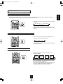
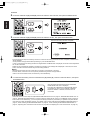
1. Press the BAND button or the TUNER button
repeatedly until the SIRIUS mode is selected.
�When some channels are skipped
• Press and hold down the AUDIO ASSIGN button on the
front panel for more than 3 seconds.
• Then SR ~ is displayed.
2. Press the TUNING UP(+)/DOWN(-) buttons
repeatedly to select SR 000.
• Then the skipped channels are rest.
• Then your SIRIUS Satellite Radio ID is displayed. Write
it below.
SIRIUS ID :
3. To sign up, access the
website at
"http://activate.siriusradio.com" or call "1-888539-SIRIUS(7474)".
31
ENGLISH
• This receiver is a SIRIUS Satellite Radio Ready® receiver. You can receive SIRIUS® Satellite Radio by connecting to the
SiriusConnect Home Tuner kit (sold separately) and subscribing the SIRIUS service.
ENGLISH
RD-7503(A)2008.11.41:45PM페이지 32
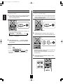
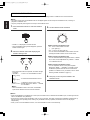
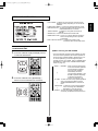
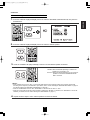
Direct search
Category search
• You can select a SIRIUS Satellite Radio channel directly
by entering its number.
• Category search allows you to select the desired
channel by the selected category.
1. In the SIRIUS mode, press the SEARCH MODE
1. In the SIRIUS mode, press the SEARCH MODE
button to select the direct search mode, then
press the ENTER button.
button to select the category search mode, then
press the ENTER button.
• Then a category is displayed.
• Each time the SEARCH MODE button is pressed, the
search mode changes as follows:
→ DIR SRCH → CAT SRCH →
OFF
(Direct search)
2. While displaying a category name, select the
(Category search)
desired category, then press the ENTER button.
• Then "SR - - -" is displayed.
2. While displaying "SR - - -", select the desired
channel number with pressing the NUMERIC
(0~9) buttons.
Examples:
For "3" :
For "27" :
• Each time the SELECT ◀/▶ buttons are pressed, one
of different categories is selected.
• When a category name disappears, repeat again from
the above step 1.
For "124" :
• When "SR - - -" disappears, repeat again from the
above step 1.
3. While displaying the selected category, select
the desired channel.
32
RD-7503(A)2008.11.41:45PM페이지 33
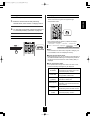
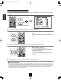
Presetting channels
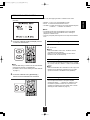
Displaying SIRIUS information
• You can store up to 30 preferred channels in the memory.
• You can display SIRIUS information such as channel
name, artist name, song title and signal strength.
1. Select the desired channel with preforming
ENGLISH
• In the SIRIUS mode,
channel search, direct search or category search.
2. To memorize the channels, perform the steps 2 to
4 in "Manual presetting" procedure on page 30.
Preset search
• In the SIRIUS mode, select the desired preset channel.
• Each time the DISPLAY button is pressed, the display
mode changes as follows:
→ Channel name → Song title → Artist name → Composer name
Volume ← Surround mode ← Signal input ← Signal strength ← Category ←
("EXCEL(LENT)", "GOOD", "WEAK", "NO SIG(NAL)")
�Note:
• If the information on artist name, song title or category, etc.
is not available, it will not be displayed correctly.
�Signal strength display mode
• If the reception is poor, you can check the signal strength of
the SIRIUS Satellite Radio signal and adjust the position of
the SiriusConnect Home antenna until "EXCEL(LENT)" is
displayed.
�Error message and status
• If an operation takes longer than usual or an error occurs,
one of the following messages may be displayed.
Status
Message
ANTENNA
UPDATING
SUB-UPDT
(updated)
The SiriusConnect Home tuner is not
connected properly. Check it.
Displayed while the encoding code is
being updated. Please wait.
Displayed while updating contract
information. Please wait.
The signal cannot be received.
NO SIG(NAL)
Reposition your SiriusConnect Home
Tuner antenna.
LINKING
The selected channel is not currently
broadcasting. Select another channel.
CHECK SR
TUNER
33
The SiriusConnect Home tuner is not
connected properly. Check it.
RD-7503(A)2008.11.41:45PM페이지 34
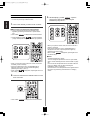
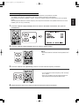
Parental lock
3. While displaying "CODE
", input the
password (4-digit number) with using the
NUMERIC (0~9) buttons.
ENGLISH
• You can lock the channels that you do not want to receive
or unlock the previously locked channels.
1. Tune in the channel you want to lock or unlock.
�When tuning in the previously locked channels.
① Tune in the channels to which the parental lock is
applied by performing direct search or preset search
only.
• Then "CODE
" is displayed for several seconds.
② While displaying "CODE
", input the password
(4-digit number) with using the NUMERIC (0~9) buttons.
• When you input the correct code, the current channel is
locked or unlocked.
• If the wrong password is input, "CODE ERR(OR)" is
displayed. In this case, input the password again by
performing the steps 2 and 3.
• When "CODE
" disappears, repeat again fromt
the above step 2.
�Notes:
• The default password is "0000".
You can change this password to new one. (For details,
refer to "When selecting the EDIT LOCK CODE" on page
50.)
• You can also set the parental lock on the INPUT SETUP
menu. (For details, refer to "When selecting the
PARENTAL LOCK" on page 49.)
• The channels to which the parental lock is applied cannot
be tuned in by performing channel search or category
search.
• When you input the correct code, the current channel can
be heard(, not be unlocked).
• If the wrong password is input, "CODE ERR(OR)" is
displayed. In this case, input the password again by
performing the steps ① and ②.
• When "CODE
" disappears, repeat again from the
above step ①.
2. Press and hold down the ENTER button for more
than 3 seconds.
• Then "CODE
" is displayed for several seconds.
34
RD-7503(A)2008.11.41:45PM페이지 35
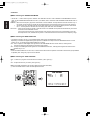
• The analog signals from the EXTERNAL INs as well as the digital signals from the HDMI IN, the OPTICAL or the COAXIAL
DIGITAL IN can be heard but cannot be recorded.
• When recording the analog signals from CD, F.AUX, VIDEO 1~3, be sure to select "ANALOG" for the AUDIO MODE.
(For details, refer to "When selecting the AUDIO MODE" on page 46.)
• The volume and tone (bass, treble) settings have no effect on the recording signals.
Dubbing from video components onto
VIDEO 1
Dubbing the audio and video signals
separately onto VIDEO 1
�Note :
• To dub the audio and video signals separately, you
should select these recording sources with pressing the
INPUT SELECTOR buttons on the remote control, not
the INPUT SELECTOR knob on the front panel.
1. Select the desired of VIDEO 2(/iPod) ~ 3 as a
recording source except VIDEO 1.
Example: When dubbing the VIDEO 2(/iPod) video signal
and the CD audio signal separately onto
VIDEO 1.
1. Select VIDEO 2/iPod as a video recording source.
2. Start recording on the VIDEO 1.
3. Start play on the desired input.
• The audio and video signals from the desired input will
be dubbed onto the VIDEO 1 and you can enjoy them
on the TV set and from the speakers.
2. Select CD as an audio recording source.
�To record audio signals
• Connect the AUDIO IN/OUT jacks of "VIDEO 1" to
audio recording equipment such as a tape deck, an MD
recorder, etc. and select the desired of tuner, CD,
F.AUX, TAPE, BT and VIDEO 2(/iPod)~3 as a recording
source. Then you can record the audio signals from the
selected input.
3. Start recording on the VIDEO 1.
4. Start play on the VIDEO 2/iPod and the CD
respectively.
• The audio signal from the CD and the video signal from
the VIDEO 2/iPod will be dubbed and you can enjoy them
on the TV set and from the speakers.
�Note :
• Be sure to observe the order of the above steps 1 and 2.
35
ENGLISH
RECORDING
RD-7503(A)2008.11.41:45PM페이지 36
ENGLISH
DIGITAL AUDIO RECORDING WITH MD RECORDER
• Only when the OPTICAL DIGITAL OUT of this receiver
is connected to the OPTICAL DIGITAL IN of the MD
recorder or CD recorder, you can enjoy high-quality
sound of digital recording without converting the
original signals. Refer to "CONNECTING VIDEO
COMPONENTS", "CONNECTING AUDIO
COMPONENTS" and "CONNECTING DIGITAL INS
AND OUT" on pages 6 ~8 and the operating
instructions of the MD recorder or CD recorder.
2. For digital recording, select the digital input as
recording signal input.
�Notes:
• Depending on the digital audio signal format input into
the HDMI IN connector, some digital signals cannot be
output from the OPTICAL DIGITAL OUT jack.
• Digital recording is available for the digital audio
program sources such as CDs, MDs, some DVDs, etc.
• There are some restrictions on recording digital signals.
When making digital recordings, refer to the operating
instructions of your digital recording equipment to know
what restrictions are imposed.
1. Select the desired of CD, F.AUX, VIDEO 1~3 as
a recording source.
�Note :
• If the AUDIO MODE is set to the mode other than
"DIGITAL" for the corresponding recording source on
the INPUT SETUP menu, the digital audio signals from
the selected digital input will not be output and there will
be no recording. (For details, refer to "When CD, F.AUX,
VIDEO 1~3 is selected as an input source" on page 22
and "When selecting the AUDIO MODE" on page 46.)
3. Start recording on the component connected to
the OPTICAL DIGITAL OUT.
�In case of recording the digital audio signal input
into a HDMI IN connector
• Select the desired recording source to which the HDMI
IN is connected and assigned and then perform the
steps 3 and 4 (, but ignore the step 2).
4. Start play on the desired input.
�Note :
• If the AUDIO MODE is set to the mode other than
"HDMI" for the corresponding recording source on the
INPUT SETUP menu, the digital audio signals will not be
output and there will be no recording. (For details, refer
to "When selecting the AUDIO MODE" on page 46.)
36
RD-7503(A)2008.11.41:45PM페이지 37
OTHER FUNCTIONS
• The sleep timer allows the system to continue to operate for a specified period of time before automatically shutting off.
• To set the receiver to automatically turn off after the specified period of time.
• Each time this button is pressed, the sleep time changes
as follows:
→ 10 → 20 → 30 → --- → 90 → OFF
Unit : minutes
• While operating the sleep timer, "
" lights up.
• When the sleep time is selected, the fluorescent display is
dimly lit.
Adjusting the brightness of the fluorescent display
• Each time this button is pressed, the brightness of the
fluorescent display changes as follows:
→ ON → dimmer → OFF
• In the display OFF mode, pressing any button will restore
the display ON mode.
Displaying the operation status
During playback,
• Each time this button is pressed, the display mode
changes as follows:
→
Signal
Input
→
Surround
mode
→
Volume
→
Input
source
• When the EXTERNAL IN is selected as an input source,
the surround mode is not displayed.
• When SIRIUS Satellite Radio function is available in your
country, for details on the SIRIUS information, see
"Displaying SURIUS information" on page 33.
37
ENGLISH
Operating the sleep timer
RD-7503(A)2008.11.41:45PM페이지 38
ROOM 2 SOURCE PLAYBACK
ENGLISH
• This function allows enjoying one source in the main room and playing another in a different room at the same time.
�Notes:
• The analog signals from the EXTERNAL INs and the digital signals cannot be output to the different room, meaning no
playback in a different room.
• Only the (composite) video signals can be output to the different room.
1. Press the ROOM 2 button to enter the ROOM 2
3. Set the selected mode as desired.
mode.
• ROOM 2 ~ is displayed for several seconds.
• When the ROOM 2 setting mode disappears, press the
ROOM 2 button again.
■When selecting the ROOM 2 mode.
ON : To turn on the ROOM 2 function.
� ("R2" lights up.)
OFF : To turn it off. ("R2" goes off.)
• You can also set the ROOM 2 mode to ON or OFF with
pressing the ROOM 2 button on the remote control.
2. Select the desired mode while displaying the
ROOM 2 setting mode.
■When selecting the ROOM 2 input.
• You can select the desired among MAIN source, TUNER,
CD, F.AUX, TAPE, BT(Bluetooth IN), VIDEO 1 ~ VIDEO
3 as a ROOM 2 source.
■When selecting the ROOM 2 volume.
• You can adjust the volume on the power amplifier
assigned to "BACK← →ROOM 2" or "ROOM 2" when
the ROOM 2 speaker terminals are connected to the
speakers in a different room. (For details, refer to "When
selecting the AMP ASSIGN" on page 41.)
• Each time these buttons are pressed, the mode changes
as follows :
→ ROOM 2 ~ : To turn on or off the ROOM 2 function.
(ROOM 2 mode)
�
IN ~
4. Start play on the component related to the
: To select the desired ROOM 2 source.
ROOM 2 source.
(ROOM 2 input)
�
→ VOL ~
: To adjust the volume on the power
(ROOM 2 volume) amplifier assigned to "BACK← →ROOM
2" or "ROOM 2".
�Note :
• When the ROOM 2 mode is set to OFF, the ROOM 2
input and the ROOM 2 volume cannot be selected.
�Notes:
• When the EXTERNAL IN is selected as a main input, if the MAIN source is selected as a ROOM 2 input, no audio signal can be
heard in the different room (ROOM 2).
• Even when this receiver enters the standby mode, in such a case that "R2" lights up still and the STANDBY indicator lights up
blue as it does in the operating mode, meaning only the ROOM 2 circuitry operates, the ROOM 2 source can be played
independently.
• When you do not use the ROOM 2 function, turn off the ROOM 2 function to save electricity.
38
RD-7503(A)2008.11.41:45PM페이지 39
• The OSD (On-Screen Display) menu is a setting menu that is displayed on the monitor TV and allows you to perform the setup
procedures easily. In most situations, you will only need to set this once during the installation and layout of your home theater, and it
rarely needs to be changed later.
The OSD menu consists of 6 main menus ; system setup, input setup, speaker / room EQ setup, CH level setup,sound parameter
and multi room setup. These menus are then divided up into various sub-menus.
■Note:
• The OSD menu and the momentary OSD can be displayed via the (composite) VIDEO MONITOR OUT only.
■Navigating through the OSD menu
• The explanations here assume you are using the buttons on the remote control when performing the OSD menu operation.
However, you can use the buttons on the front panel as well.
The buttons on the front panel correspond to those on the remote control as shown below.
1. Turn the menu screen on.
MULTI
• The main menu will be shown.
• To turn the menu screen off, press this button again.
2. Select the desired menu using the CURSOR UP(▲)/DOWN(▼) buttons.
39
ENGLISH
OSD Menu Settings
RD-7503(A)2008.11.41:45PM페이지 40
ENGLISH
3. Confirm your selection.
�When selecting the SYSTEM SETUP
�When selecting the INPUT SETUP
45
41
�When selecting the SPEAKER /ROOM EQ SETUP
�When selecting the CH LEVEL SETUP
51
57
�When selecting the SOUND PARAMETER
�When selecting the MULTI ROOM SETUP
59
61
• For the setting details, see page in �.
• Adjust the setting(s) in each setting category to your preference.
• When the SETUP button is pressed on a sub-menu, the menu screen will be turned off.
40
RD-7503(A)2008.11.41:45PM페이지 41
• AMP ASSIGN : To assign the surround back channels' power
amplifier correctly depending on how to use the
speakers.
• SUBWOOFER MODE : To select the desired subwoofer mode.
• HDMI AUDIO OUT : To output the digital audio signals from the
HDMI MONITOR OUT connector.
• TONE CONTROL : To adjust the tone (bass and treble) as
desired.
• CINEMA EQ : To select the desired cinema EQ mode.
• MOMENTARY OSD : To turn on or off the OSD that shows the
status corresponding to each operation
momentarily.
• OSD POSITION ADJUST : To adjust the position of the
momentary OSD and the OSD menu.
When selecting the items other than OSD
POSITION ADJUST
�When selecting the AMP ASSIGN
1. Press the CURSOR UP(▲)/DOWN(▼) buttons
• The surround back channels' power amplifier can drive
the surround back speakers, the ROOM 2 speakers or
the front bi-amp capable speakers. Depending on how
to use the speakers, you should assign the power
amplifier correctly. (For details, refer to "CONNECTING
SPEAKERS" on page 9 and "CONNECTING ROOM 2
OUTS" on page 11.)
to select the desired item.
→ BACK← →ROOM 2 : When connecting this receiver
to the surround back speakers
and the ROOM 2 speakers
both, the power amplifier
automatically drives the
�
surround back speakers or the
ROOM 2 speakers depending
on whether the ROOM 2
function is turned off or on.
BI - AMP : To drive the front bi-amp capable speakers
when connecting the FRONT and the
�
SURROUND BACK/MULTI channels to
them.
SURR BACK : To drive the surround back speakers
when connecting the SURROUND
�
BACK/MULTI channels to them.
→ ROOM 2 : To drive the ROOM 2 speakers when
connecting the ROOM 2 channels to them.
2. Press the CURSOR LEFT(◀)/RIGHT(▶)
buttons to set the selected item as desired.
41
ENGLISH
SETTING THE SYSTEM SETUP
RD-7503(A)2008.11.41:45PM페이지 42
Continued
ENGLISH
�When selecting the SUBWOOFER MODE
• "SW PLUS+" mode is valid only when "FRONT" and "CENTER" are set to "FULL RANGE" and "SUBWOOFER" is set to
"YES" on the SPEAKER/ROOM EQ SETUP menu. (For details, refer to "SETTING THE SPEAKER/ ROOM EQ SETUP" on
page 51.)
NORMAL : When the low frequency signals of channels set to "FULL RANGE " are reproduced from those channels only. In
this mode, the low frequency signals that are reproduced from the subwoofer channel is only the low frequency
�
signals of LFE (from the multi-channel sources that contains LFE (Low Frequency Effects) channel, also called
the ".1" channel) and the channels set to the setting value other than "FULL RANGE".
SW PLUS+ : When the low frequency signals of channels set to "FULL RANGE" are reproduced simultaneously from those
channels and the subwoofer channel.
In this mode, the low frequency range expands more uniformly through the room, but depending on the size
and shape of the room, interference may result in a decrease of the actual volume of the low frequency range.
�When selecting the HDMI AUDIO OUT
• The HDMI connection can carry uncompressed digital video signals and digital audio signals.
Depending on whether the digital audio signals input into the HDMI IN are output from the HDMI MONITOR OUT of this
receiver or not, you should set the HDMI AUDIO OUT correctly.
OFF : Not to output the HDMI digital audio signals from the HDMI MONITOR OUT of this receiver, meaning these
�
signals are heard from the speakers connected to this receiver.
ON : To output the HDMI digital audio signals from the HDMI MONITOR OUT, meaning these signals are heard from the
speakers of your TV.
�Note:
• When the HDMI AUDIO OUT is set to ON, no sound will be heard from the speakers connected to this receiver (except ROOM
2 speakers) even though any input source is selected.
�When selecting the TONE CONTROL
OFF : To listen to a program source without the tone effect. ("DIR" lights up.)
�
ON : To adjust the tone for your taste. ("DIR" goes off.)
◆When the TONE CONTROL is set to ON to adjust the tone (bass and treble)
①. Press the ENTER button to enter the tone adjustment mode.
42
RD-7503(A)2008.11.41:45PM페이지 43
Continued
ENGLISH
②. Press the CURSOR UP(▲)/DOWN(▼) buttons to select the desired tone mode.
③. Press the CURSOR LEFT(◀)/RIGHT(▶) buttons to adjust the selected tone as desired.
• The tone level can be adjusted within the range of -10 ~
+10 dB.
• In general, we recommend the bass and treble to be
adjusted to 0 dB (flat level).
• Extreme settings at high volume may damage your
speakers.
• To complete tone adjustment, repeat the above steps ②
and ③.
■When selecting the CINEMA EQ
OFF : To turn off the cinema EQ function.
�
ON : To compensate for edgy or shrill movie sound tracks.
■When selecting the MOMENTARY OSD
ON : To turn on the OSD function that shows the status corresponding to each operation on this unit momentarily.
�
OFF : To turn it off.
■Note :
• The OSD menu and the momentary OSD can be displayed via the (composite) VIDEO MONITOR OUT only.
43
RD-7503(A)2008.11.41:45PM페이지 44
When selecting the OSD POSITION ADJUST
ENGLISH
• You can adjust the position of the momentary OSD and the OSD menu that are displayed on the monitor TV.
1. Press the CURSOR UP(▲)/DOWN(▼) buttons to select the OSD POSITION ADJUST, then press the
ENTER button.
2. Press the CURSOR UP(▲)/DOWN(▼)/LEFT(◀)/RIGHT(▶) buttons to adjust the position of the momentary
OSD and the OSD menu as desired.
44
RD-7503(A)2008.11.41:45PM페이지 45
• This menu allows you to make the various settings
depending on how to use the input sources connected to
this receiver.
When selecting the items other than NAME, PARENTAL LOCK, EDIT LOCK MODE
1. Press the CURSOR UP(▲)/DOWN(▼) buttons to select the desired input source, then press the ENTER
button.
Example: When selecting the VIDEO 1
�When selecting the menu of page 2 or page 1.
• Press the CURSOR UP(▲)/DOWN(▼) buttons to select
"GO TO NEXT ~ ", then press the ENTER button.
2. Press the CURSOR UP(▲)/DOWN(▼) buttons to select the desired item.
■Note :
• Depending on the input source, some items other than DC
TRIGGER cannot be selected.
3. Press the CURSOR LEFT(◀)/RIGHT(▶) buttons to set the selected item as desired.
45
ENGLISH
SETTING THE INPUT SETUP
RD-7503(A)2008.11.41:45PM페이지 46
Continued
ENGLISH
■When selecting the HDMI ASSIGN
• You should assign the connected HDMI INs to the desired of VIDEO 1 ~ VIDEO 3.
(For details, refer to "CONNECTING VIDEO COMPONENTS" on pages 6 ~ 7.)
• You can select the desired of HDMI 1 ~ HDMI 3.
■Note :
• In such a case that a HDMI IN is assigned to two input sources or more, when these input sources are selected, the
uncompressed digital video signals (and digital audio signals when the HDMI AUDIO OUT is set to ON) input into the same
HDMI IN can be output from the HDMI MONITOR OUT of this receiver.
■When selecting the VIDEO ASSIGN
• You should assign the connected COMPONENT VIDEO INs to the desired of VIDEO 1 ~ 3.
(For details, refer to "CONNECTING VIDEO COMPONENTS" on pages 6 ~ 7.)
• You can select the desired of COMP 1 ~ 2.
■Note :
• In such a case that a COMPONENT VIDEO IN is assigned to two input sources or more, when these input sources are
selected, the component video signals can be viewed from the same COMPONENT VIDEO IN.
■When selecting the AUDIO ASSIGN
• You should assign the connected DIGITAL INs to the desired of CD, F.AUX and VIDEO 1 ~ VIDEO 3.
(For details, refer to "CONNECTING DIGITAL INS AND OUT" on page 8.)
• You can select the desired of OPT 1 ~ 2 and COAX 1 ~ 2.
■Note :
• In such a case that a DIGITAL IN is assigned to two input sources or more, when these input sources are selected, the digital
audio signals can be heard from the same DIGITAL IN.
■When selecting the AUDIO MODE
• You can select the desired audio input signal to be played.
■Notes :
• Be sure to set the AUDIO MODE to the audio input which is connected and assigned to the selected input source.
• When the HDMI AUDIO OUT is set to ON, no sound will be heard from the speakers connected to this receiver (except ROOM
2 speakers).
• When the AUDIO MODE is set to HDMI, you should connect the HDMI INs and set the HDMI ASSIGN correctly. If not, the
HDMI input flickers on the unit's display and no sound will be heard.
• When the AUDIO MODE is set to DIGITAL, you should connect the DIGITAL INs and set the AUDIO ASSIGN correctly. If not,
the digital input flickers on the unit's display and no sound will be heard.
→ AUTO : When there are multiple audio input signals, the audio input signals are detected and the audio input signal to be
played is selected automatically in the priority order of them :
�
HDMI audio > DIGITAL audio > ANALOG audio
HDMI : The signal that is input into the HDMI IN is always played.
�
DIGITAL : The signal that is input into the OPTICAL or the COAXIAL DIGITAL IN is always played.
�
→ ANALOG : The signal that is input into the analog AUDIO INs is always played.
46
RD-7503(A)2008.11.41:45PM페이지 47
Continued
■When selecting the AUTO SURROUND
ON
: The optimum surround mode will be automatically selected depending on the signal
(Auto surround mode)
format being input.
�
OFF
: You can select the desired of different surround modes selectable for the signal being
(Manual surround mode) input with using the MULTI CONTROL knob or the SURROUND MODE UP/DOWN ( >/< )
buttons. (For details, refer to "When selecting the manual surround mode with pressing the
SURROUND MODE button on the front panel" on page 25.)
■Notes :
• Even when the auto surround mode is selected and the same type of digital signal format is being input, the optimum surround
mode may vary depending on whether the speaker type is set to "NO" or not.
• When the auto surround mode is selected, the surround modes other than the optimum surround mode cannot be selected.
■When selecting the AV SYNC
• There may be a slight time delay between the video and audio signals in case that some video playback equipments may
process the video signals later than the audio signals due to signal processing procedure, etc.. Should this happen, you can
adjust the time delay of audio signals to synchronize the sound with the picture.
• The time delay can be adjusted within the range of 0 ~ 200 msec.
■When selecting the DC TRIGGER
• To turn on the component connected to the DC TRIGGER OUT jack when this input source is selected, you should set the DC
TRIGGER to ON for this input source.
OFF : To turn off the DC trigger function.
�
ON: To turn it on.
• For details, refer to "CONNECTING DC TRIGGER OUT" on page 11.
■When selecting the HD AUDIO
• When the source components that cannot support the HD audio signal format (such as Dolby Digital Plus, Dolby TrueHD,
DTS-HD High Resolution Audio, DTS-HD Master Audio, etc.) are connected to the HDMI IN of this receiver, some components
may not output any audio signals from its HDMI OUT.
In this case, you should set the HD AUDIO to OFF to play the audio signals other than the HD audio signals. (For details on
the audio signal format, refer to the operating instructions of the source component.)
ON : To play the audio signals (including the HD audio signals).
�
OFF : To play the audio signals other than the HD audio signals.
47
ENGLISH
• Depending on how to select a surround mode, you can select the auto surround mode or the manual surround mode.
RD-7503(A)2008.11.41:45PM페이지 48
When selecting the NAME
ENGLISH
• You can give names to the input sources other than tuner.
• Up to 7 characters can be entered for each name.
3. Press the CURSOR LEFT(◀)/ RIGHT(▶)
buttons to select the desired digit.
1. Press the CURSOR UP(▲)/DOWN(▼) buttons
to select the desired input source, then press
the ENTER button.
• Then the selected digit will flicker.
4. Press the CURSOR UP(▲)/DOWN(▼) buttons
to enter the desired character on the flickering
digit.
Example: When selecting the VIDEO 1
2. Press the CURSOR UP(▲)/DOWN(▼) buttons
• You can enter the desired among blank, A ~ Z,
a ~ z, 0 ~ 9, (, ), �, +, , , -, ., /.
to select the NAME, then press the ENTER
button.
5. Repeat the above steps 3 and 4 to enter the
desired characters on the rest of the digits.
6. Confirm your entry.
• The name is stored in the memory.
■To resume its factory input source name.
• Make a blank on each digit and press the ENTER button.
• The first digit flickers.
48
RD-7503(A)2008.11.41:45PM페이지 49
When selecting the PARENTAL LOCK
1. Press the CURSOR UP(▲)/DOWN(▼) buttons to select the PARENTAL LOCK, then press the ENTER
button.
2. Input the password(4-digit number) with using the NUMERIC (0~9) buttons, then press the ENTER button.
• When you input the correct code, the current channel is locked (or unlocked).
• If the wrong password is input, "INCORRECT CODE" is displayed. In this case, input the password again, performing the
steps 1 and 2.
■Note :
• The default password is "0000".
You can change this password to new one. (For details, refer to "When selecting the EDIT LOCK CODE" on page 50.)
3. Press the TUNING UP(+)/DOWN(-) buttons to
4. Press the CURSOR LEFT(◀)/ RIGHT(▶)
select the channel you want to lock or unlock.
buttons to set the selected station as desired.
• Each time the CURSOR LEFT(◀)/ RIGHT(▶) buttons
are pressed, "LOCK" or "UNLOCK" is selected.
5. Repeat the above steps 3 and 4 to set the channels as desired.
49
ENGLISH
• You can select the PARENTAL LOCK on the TUNER CONFIGURATION menu only while listening to SIRIUS Satellite Radio.
• You can lock the channels that you do not want to receive or unlock the previously locked channels.
RD-7503(A)2008.11.41:45PM페이지 50
When selecting the EDIT LOCK CODE
ENGLISH
• You can select the EDIT LOCK CODE on the TUNER CONFIGURATION menu only while listening to SIRIUS Satellite
Radio.
• You can change the password to the desired.
1. Press the CURSOR UP(▲)/DOWN(▼) buttons to select the EDIT LOCK CODE, then press the ENTER
button.
2. Input the current password(4-digit number), then press the ENTER button.
• When you input the correct code, "NEW :����" is displayed.
• If the wrong password is input, "INPUT ERROR" is displayed. In this case, input the password again, performing the steps
1 and 2.
3. Input the new password(4-digit number), then press the ENTER button.
• If the correct password is input, "MODIFIED" is displayed and the new password is modified.
■Note :
• Do not forget the password.
If you forgot your password, you cannot lock or unlock the channel.
50
RD-7503(A)2008.11.41:45PM페이지 51
• After you have installed this receiver and connected all the components, you should adjust the speaker settings for the
optimum sound acoustics according to your environment and speaker layout.
• Even when you change speakers, speaker positions, or the layout of your listening environment, you should adjust the
speaker settings, too.
• When performing the AUTO SETUP procedure, you need not perform the SPEAKER CONFIGURATION, SPEAKER
DISTANCE, SPEAKER CROSSOVER and CH LEVEL SETUP procedures.
• AUTO SETUP : To set the speaker setup and channel level setup
automatically.
• SPEAKER CONFIGURATION : To adjust the speakers depending on
whether they are connected or not.
• SPEAKER DISTANCE: To select the distance between the listening
position and each speaker to set the delay
time automatically for optimum surround
playback.
• SPEAKER CROSSOVER : To select the desired crossover
frequency.
• ROOM EQ SETUP : To select the desired room EQ mode.
When selecting the AUTO SETUP
• Auto Setup lets you avoid troublesome listening-based speaker setup and achieve good surround sound. Auto Setup has the
feature that provides the optimum listening environment at the listening position in your room, where there are often multiple
listeners viewing programs together.
You should connect the supplied microphone to the SETUP MIC jack so that this receiver can analyze the information from a
series of test tones emitted from speakers at main listening position and can adjust the configuration, distance, sound level,
crossover frequency and frequency response of each speaker automatically.
• If you want to personalize your speaker setup and channel level setup by making the settings manually, perform the "When
selecting the SPEAKER CONFIGURATION" on page 53, "When selecting the SPEAKER DISTANCE" on page 54, "When
selecting the SPEAKER CROSSOVER" on page 55, "Adjusting each channel level with test tone" on page 26 and "Adjusting
the current channel level" on page 27.
• After the auto setup has been completed, set the room EQ as desired. (For details, refer to "When selecting the ROOM EQ
SETUP" on page 56.)
�Preparations
①. Check that the speakers are securely connected to this receiver.
• If your subwoofer has adjustable volume and crossover frequency, set the volume halfway and set the crossover
frequency to the maximum or the low pass filter off.
②. Connect the supplied microphone to the SETUP MIC jack on the front panel.(For details, refer to "SETUP MIC JACK" on
page 14.)
■Notes :
• Because the microphone for Auto Setup is designed for use with this receiver, to use the auto setup function, do not use a
microphone other than the one supplied with this receiver.
• After you have completed the auto setup procedure, disconnect the microphone.
1. Place the microphone on a flat level surface at the listening position.
• If possible, use a tripod, etc. to attach the microphone at the same height as your ears would be when you are seated in your
listening position.
• Ensure there are no obstacles between the speakers and the microphone.
51
ENGLISH
SETTING THE SPEAKER / ROOM EQ SETUP
RD-7503(A)2008.11.41:45PM페이지 52
Continued
ENGLISH
2. Press the CURSOR UP(▲)/DOWN(▼) buttons to select the AUTO SETUP, then press the ENTER button.
3. Press the CURSOR UP(▲)/DOWN(▼) buttons to select the START, then press the ENTER button.
When the auto setup has been completed.
• Loud test tones are output successively and then if a series of auto setup procedure has been completed, "COMPLETED"
will be displayed.
• To stop the auto setup procedure while performing it, press the ENTER button.
In such a case that the auto setup procedure is stopped before "COMPLETED" is displayed, the results of each adjustment
can not be memorized.
• If there may be a problem with speaker or microphone connection, error message will be displayed. In this case, turn off the
power, check the connection and then retry the auto setup procedure.
■Notes :
• Because the test tones are loud, ensure there no infants or small children in the room.
• For best results, ensure the room is as quiet as possible during the auto setup procedure.
If there is too much ambient noise, the results may not be satisfactory.
4. To memorize the results, press the CURSOR LEFT(◀)/ RIGHT(▶)
buttons to select the APPLY, then press
the ENTER button.
• Then the results are memorized and the SPEAKER/
ROOM EQ SETUP menu is displayed.
• Each time the CURSOR LEFT(◀)/ RIGHT(▶) buttons
are pressed, the APPLY or the CANCEL is selected.
• When the CANCEL is selected, the results are not
memorized.
• Check the results on each setup menu(SPEAKER CONFIGURATION menu on page 53, SPEAKER DISTANCE menu on
page 54, SPEAKER CROSSOVER menu on page 55 and CH LEVEL SETUP menu for "CALIBRATE" mode on page 57).
• If the results are not satisfactory, you can retry the auto setup procedure or personalize your speaker setup and channel
level setup by making the settings manually. (For details, refer to "When selecting the SPEAKER CONFIGURATION" on
page 53, "When selecting the SPEAKER DISTANCE" on page 54, "When selecting the SPEAKER CROSSOVER" on
page 55, "Adjusting each channel level with test tone" on page 26 and "Adjusting the current channel level" on page 27.)
52
RD-7503(A)2008.11.41:45PM페이지 53
Continued
When selecting the SPEAKER CONFIGURATION
1. Press the CURSOR UP(▲)/DOWN(▼) buttons to select the SPEAKER CONFIGURATION, then press the
ENGLISH
ENTER button.
2. Press the CURSOR UP(▲)/DOWN(▼) buttons to select the desired speaker.
3. Press the CURSOR LEFT(◀)/ RIGHT(▶) buttons to set the selected speaker as desired.
YES/NO: Select the desired depending on whether the
speakers are connected or not.
2CH/1CH: Select the desired depending on the number of
speakers connected to SURROUND BACK/
MULTI channels.
�Notes :
• When speakers are not set to "NO", you should set their distances from listening position and crossover frequencies
according to their frequency characteristics. (For details, refer to "When selecting the SPEAKER DISTANCE" on page 54
and "When selecting the SPEAKER CROSSOVER" on page 55.)
• When the "SURROUND" is set to "NO", "BACK/MULTI" cannot be set to "2CH" or "1CH".
• When the surround back channels' power amplifier is assigned to "BI-AMP" or "ROOM 2", the "BACK/MULTI" cannot be
selected. (For details, refer to "When selecting the AMP ASSIGN" on page 41.)
4. Repeat the above steps 2 and 3 until the speakers are all set as desired.
53
RD-7503(A)2008.11.41:45PM페이지 54
When selecting the SPEAKER DISTANCE
1. Press the CURSOR UP(▲)/DOWN(▼) buttons to select the SPEAKER DISTANCE, then press the ENTER
ENGLISH
button.
2. Press the CURSOR UP(▲)/DOWN(▼) buttons to select the desired item.
�Note :
• You cannot select the subwoofer and the speakers set to
"NO".
3. Press the CURSOR LEFT(◀)/RIGHT(▶) buttons to set the selected item as desired.
�When selecting the desired unit
• You can select either METERS or FEET.
• Once a unit is selected, the distances are automatically
changed in the selected unit.
�When setting the distance
• You can set the distance within the range of 0.1 ~ 9.0
meters in 0.1 meter intervals (or 0.5 ~ 30 feet in 0.5 feet
intervals).
4. Repeat the above steps 2 and 3 until the distances are all set as desired.
�About the speaker distance
When enjoying multi-channel surround playback with Dolby Digital and DTS sources, etc., it is ideal that the center, surround
and surround back speakers should be the same distance from the main listening position as the front speakers. By entering
the distance between the listening position and each speaker, the delay times of center, surround and surround back speakers
are automatically adjusted to create an ideal listening environment virtually as if the center, surround and surround back
speakers were at their ideal locations respectively.
54
RD-7503(A)2008.11.41:45PM페이지 55
• Set the crossover frequency according to the frequency characteristics of the speakers connected.
(For details on the frequency characteristics, refer to the operating instructions of the speakers.)
• If the frequency range of your speaker is 100 Hz ~ 20 kHz, the crossover frequency should be set to 100 Hz (or slightly
higher).
• The low frequencies below the crossover frequency are to output from subwoofer or the speakers which are set to "FULL
RANGE" (when not using a subwoofer).
1. Press the CURSOR UP(▲)/DOWN(▼) buttons to select the SPEAKER CROSSOVER, then press the
ENTER button.
2. Press the CURSOR UP(▲)/DOWN(▼) buttons to select the desired speaker.
�Note :
• You cannot select the subwoofer and the speakers set to
"NO".
3. Press the CURSOR LEFT(◀)/RIGHT(▶) buttons to set the crossover frequency as desired.
• You can adjust the crossover frequency within the range
of 40 ~ 250 Hz.
• Select "FULL RANGE" when the selected speaker can
fully reproduce the low frequencies below 40 Hz.
4. Repeat the above steps 2 and 3 until the crossover frequencies are all set as desired.
55
ENGLISH
When selecting the SPEAKER CROSSOVER
RD-7503(A)2008.11.41:45PM페이지 56
ENGLISH
When selecting the ROOM EQ SETUP
• The room EQ is a kind of room equalizer for your speakers. According to the acoustic characteristics of your room
measured by the auto setup, the room EQ automatically adjusts the frequency response of your speakers.
• If you use different brands or sizes of speakers for some channels or have a room with unique acoustic characteristics,
such as walls, furniture, and the dimensions or the shape of the room, we recommend using the room EQ.
■Note :
• To use the room EQ, first you should finish measuring the acoustic characteristics of your room performing the auto setup.
(For details, refer to "When selecting the AUTO SETUP" on page 51.)
1. Press the CURSOR UP(▲)/DOWN(▼) buttons to select the ROOM EQ SETUP, then press the ENTER
button.
2. Press the CURSOR LEFT(◀)/RIGHT(▶) buttons to select the desired room EQ mode.
OFF : When turning off the room EQ.
�
ON : To adjust the frequency response of all speakers to
the flattest response.
56
RD-7503(A)2008.11.41:45PM페이지 57
SETTING THE CH LEVEL SETUP
■Note :
• Depending on the speaker settings("NO", etc.), some
channels cannot be selected.
Adjusting the current channel level
• You can adjust the current channel levels as desired. These adjusted levels are just memorized into user’s memory
("CALIBRATE"), not into preset memory("REFERENCE 1", "REFERENCE 2").
• After adjusting each channel level with test tone, adjust the channel levels either according to the program sources or to suit
your tastes.(For details, refer to "Adjusting each channel level with test tone" on page 26.)
1. Press the CURSOR UP(▲)/DOWN(▼) buttons to select the desired channel.
■When adjusting the LFE LEVEL
①. Press the CURSOR UP(▲)/DOWN(▼) buttons to select the LFE LEVEL SETUP, then press the ENTER
button.
②. Press the CURSOR UP(▲)/DOWN(▼) buttons to select the desired program source.
2. Press the CURSOR LEFT(◀)/RIGHT(▶) buttons to adjust the level of the selected channel or program
source's LFE as desired.
• The LFE level can be adjusted within the range of -10 ~ 0 dB
and other channel levels within the range of -15 ~ +15 dB
• In general, we recommend the LFE level to be adjusted to 0
dB.(However, the recommended LFE level for some early
DTS software is -10 dB.) If the recommended levels seem too
high, lower setting as necessary.
3. Repeat the above steps 1 and 2 to adjust each channel level.
57
ENGLISH
Memory mode
RD-7503(A)2008.11.41:45PM페이지 58
Memorizing the adjusted channel levels
ENGLISH
• You can memorize the adjusted channel levels into preset memory("REFERENCE 1", "REFERENCE 2") and recall the
memorized whenever you want.
1. After performing the steps 1~3 in "Adjusting the current channel level" procedure on page 57, press the
CURSOR UP(▲)/DOWN(▼) buttons to select a channel (, not the MODE (memory mode) and the LFE
LEVEL SETUP), then press the ENTER button.
• The "REFERENCE 1" indication flickers.
2. Press the CURSOR LEFT(◀)/RIGHT(▶) buttons to select the desired preset memory, then press the
ENTER button.
• Each time the CURSOR LEFT(◀) or RIGHT(▶) button is
pressed, "REFERENCE 1" or "REFERENCE 2" is
selected.
• The adjusted channel levels have now been memorized
into the selected memory.
Recalling the memorized channel levels
1. Press the CURSOR UP(▲)/DOWN(▼) buttons to select the MODE(memory mode).
• "CALIBRATE" may be displayed instead of
"REFERENCE 1" or "REFERENCE 2".
2. Press the CURSOR LEFT(◀)/RIGHT(▶) buttons to select the desired one of REFERENCE 1 and
REFERENCE 2.
• Then the channel levels memorized into the selected
preset memory are recalled.
58
RD-7503(A)2008.11.41:45PM페이지 59
• NIGHT MODE : To adjust the dynamic range compression that
makes faint sound easier to hear at low volume
levels.
• DOLBY PLII MUSIC : To adjust the various surround
parameters for optimum surround effect.
When selecting the NIGHT MODE
• This function compresses the dynamic range of previously specified parts of the Dolby Digital sound track (with extremely
high volume) to minimize the difference in volume between the specified and non-specified parts.
This makes it easy to hear all of the sound track when watching movies at night at low levels.
�Notes:
• The night mode setting is valid only when the digital signals from the Dolby Digital program source are being input.
• In some Dolby Digital softwares, the night mode setting may not be valid.
1. Press the CURSOR UP(▲)/DOWN(▼) buttons to select the NIGHT MODE, then press the
ENTER button.
2. Press the CURSOR LEFT(◀)/ RIGHT(▶) buttons to adjust the dynamic range compression as desired.
AUTO�
�
0.0 (OFF)
�
0.1
�
0.2
:
:
:
0.9
�
1.0 (MAX)
Lower compression
Higher compression
�: Valid only when the digital signals from the Dolby
TrueHD program source are being input.
59
ENGLISH
SETTING THE SOUND PARAMETER
RD-7503(A)2008.11.41:45PM페이지 60
ENGLISH
When selecting the DOLBY PLII MUSIC
• You can adjust the various surround parameters for optimum surround effect.
�Note:
• The parameter settings are valid only when listening in either Dolby Pro Logic II Music mode or the Dolby Pro Logic IIx
Music mode.
1. Press the CURSOR UP(▲)/DOWN(▼) buttons to select the DOLBY PLII MUSIC, then press the ENTER
button.
2. Press the CURSOR UP(▲)/DOWN(▼) buttons to select the desired parameter.
3. Press the CURSOR LEFT(◀)/ RIGHT(▶) buttons to adjust the selected parameter as desired.
�When selecting the PANORAMA mode
This mode extends the front stereo image to include the surround
speakers for an exciting "wraparound" effect with side wall imaging.
Select "OFF" or "ON"(default value:OFF).
�When selecting the CENTER WIDTH control
This adjusts the center image so it may be heard only from the
center speaker, only from the left/right speakers as a phantom
image, or from all three front speakers to varying degrees. The
control can be set in 8 steps from 0 to 7 (default value : 3).
�When selecting the DIMENSION control
This gradually adjusts the soundfield either towards the front or
towards the rear. The control can be set in 7 steps from -3 to
+3(default value : 0).
4. Repeat the above steps 2 and 3 to adjust other parameters.
60
RD-7503(A)2008.11.41:45PM페이지 61
SETTING THE MULTI ROOM SETUP
• ROOM 2 : To turn on or off the ROOM 2 function.
• INPUT : To select the desired ROOM 2 source.
• VOLUME : To adjust the volume on the power amplifier assigned
to "BACK ← → ROOM 2" or "ROOM 2".
�Notes:
• The analog signals from the EXTERNAL INs and the digital
signals cannot be output to the different room, meaning no
playback in a different room.
• Only the (composite) video signals can be output to the different
room.
1. Press the CURSOR UP(▲)/DOWN(▼) buttons
When selecting the ROOM 2
to select the desired item.
OFF : To turn off the ROOM 2 function.
↕
ON : To turn it on.
�Notes:
• When the ROOM 2 is set to OFF, the INPUT and the
VOLUME cannot be selected.
• When you do not use the ROOM 2 function, set the
ROOM 2 to OFF to save electricity.
When selecting the INPUT
• You can select the desired among MAIN source, TUNER,
CD, F.AUX, TAPE, BT, VIDEO 1 ~ VIDEO 3 as a ROOM 2
source.
�Note:
• When the EXTERNAL IN is selected as a main input, if the
MAIN source is selected as a ROOM 2 input, no audio
signal can be heard in the different room (ROOM 2).
�Note:
• The VOLUME setting is invalid when the AMP ASSIGN
is assigned to "BI-AMP" or "SURR BACK".
(For details, refer to "When selecting the AMP ASSIGN"
on page 41.)
2. Press the CURSOR LEFT(◀)/RIGHT(▶)
buttons to set the selected item as desired.
When selecting the VOLUME
• You can adjust the volume on the power amplifier
assigned to "BACK ← → ROOM 2" or "ROOM 2" when
the ROOM 2 speaker terminals are connected to the
speakers in a different room.(For details, refer to "When
selecting the AMP ASSIGN" on page 41.)
61
ENGLISH
• The ROOM 2 function allows enjoying one source in the main room while playing another in a different room at the
same time.
RD-7503(A)2008.11.41:45PM페이지 62
Troubleshooting Guide
ENGLISH
If a fault occurs, run through the table below before taking your receiver for repair.
If the fault persists, attempt to solve it by switching the receiver off and on again. If this fails to resolve the situation, consult your
dealer. Under no circumstances should you attempt to repair the receiver yourself. This could void the warranty.
PROBLEM
POSSIBLE CAUSE
REMEDY
No power
• The AC input cord is disconnected.
• Poor connection at AC wall outlet or the outlet is
dead or off.
• Connect cord securely.
• Check the outlet using a lamp or another
appliance.
No sound
• The speaker wires are disconnected.
• The master volume is adjusted too low.
• The MUTE button is pressed to ON.
• Incorrect selection of input source.
• Incorrect connections between the components.
• The HDMI AUDIO OUT is set to ON.
• Check the speaker connections.
• Adjust the master volume.
• Press the MUTE button to cancel the muting effect.
• Select the desired input source correctly.
• Make connections correctly.
• Set it to OFF. (For details, refer to "When
selecting the HDMI AUDIO OUT" on page 42.)
• Set the settings correctly. (For details, refer to
"SETTING THE INPUT SETUP" on page 45.)
• The settings related to audio are set incorrectly.
No sound from the surround
speakers
• Surround mode is switched off(stereo mode).
• Master volume and surround level are too low.
• Monaural source is used.
• Surround speaker setting is "NO".
• Select a surround mode.
• Adjust master volume and surround level.
• Select a stereo or surround source.
• Select the desired surround speaker setting.
No sound from the center
speaker
• Dolby Virtual Speaker, stereo mode, etc is
selected.
• Center speaker setting is "NO".
• Master volume and center level are too low.
• Select the desired surround mode.
• The input signal format or the current surround
mode cannot support the 7.1(or 6.1) surround.
• Under the proper situations, perform the 7.1(or
6.1) surround playback.(For details, refer to
"ENJOYING SURROUND SOUND" on page 25.)
• Assign the power amplifier to the surround back
channels.(For details, refer to "When selecting
the AMP ASSIGN"on page 41.)
• Adjust master volume and surround back level.
• Select the desired surround back speaker setting.
No sound from the surround back
speakers
• The surround back channels' power amplifier is
assigned to "BI-AMP" or "ROOM 2".
• Master volume and surround back level are too low.
• Surround back speaker setting is "NO".
• Select the desired center speaker setting.
• Adjust master volume and center level.
• Video connections between this unit and the
monitor TV are not made correctly.
• Incorrect selection of input source on the monitor
TV.
• The settings related to video are set incorrectly.
• Make proper video connections.
• HDMI connection between this unit and the
monitor TV are not made correctly.
• The monitor TV or other equipments do not
support HDCP.
• Make proper HDMI connection.
Noise or distorted picture
• Video format of your monitor TV, DVD player, etc.
is different from NTSC.
• Change the video format to NTSC.
Stations cannot be received
• No antenna is connected.
• The desired station frequency is not tuned in.
• Antenna is in wrong position.
• Connect an antenna.
• Tune in the desired station frequency.
• Move antenna and retry tuning.
Preset stations cannot be
received
• An incorrect station frequency has been memorized.
• The memorized stations are cleared.
• Memorize the correct station frequency.
• Memorize the stations again.
Poor FM reception
• No antenna is connected.
• The antenna is not positioned for the best reception.
• Weak signals.
• Connect an antenna.
• Change the position of the antenna.
• Install an outdoor FM antenna.
Continuous or intermittent hissing
noise during AM reception,
especially at night.
• Noise is caused by motors, fluorescent lamps or
lightning, etc.
• Keep the receiver away from noise sources.
Remote control unit does not
operate.
• Batteries are not loaded or exhausted.
• The remote sensor is obstructed.
• Replace the batteries.
• Remove the obstacle.
OSD function is not available.
• Video connections between this unit and the
monitor TV are not made correctly.
• Make proper (composite) video connections.
No picture
No picture with an HDMI
connection
• Select the input source correctly.
• Set the settings correctly. (For details, refer to
"SETTING THE INPUT SETUP" on page 45.)
• This unit will not output video signal unless the
connected equipments supports HDCP.
• Install an outdoor AM antenna.
62
RD-7503(A)2008.11.41:45PM페이지 63
�AMPLIFIER SECTION
• Power output, stereo mode, 6 Ω, THD 1.0 %, 40 Hz~20 kHz | 2×100 W
• Total harmonic distortion at -3 dB, 6 Ω, 1 kHz | 0.05%
• Intermodulation distortion
60 Hz : 7 kHz= 4 : 1 SMPTE, 6 Ω, 95 W | 0.05%
• Input sensitivity/impedance
Line (CD, TAPE, VIDEO) | 300 mV/47kΩ
• Signal to noise ratio, IHF "A" weighted
Line (CD, TAPE, VIDEO) | 100 dB
• Frequency response
Line (CD, TAPE, VIDEO), 10 Hz ~ 100 kHz | +0, -3 dB
• Output level
ROOM 2 OUT, 2.2 kΩ | 300 mV
• Bass/Treble control, 100 Hz/10 kHz | ±10 dB
• Surround mode, only channel driven
Front power output, 6 Ω, 1 kHz, THD 1.0 % | 110 W / 110W
Center power output, 6 Ω, 1 kHz, THD 1.0 % | 110 W
Surround power output, 6 Ω, 1 kHz, THD 1.0 % | 110 W / 110W
Surround back (/MULTI) / ROOM 2 power output, 6 Ω, 1 kHz, THD 1.0 %
ENGLISH
Specifications
| 110 W / 110W
�DIGITAL AUDIO SECTION
• Sampling frequency | 32, 44.1, 48, 96 kHz
• Digital input level
Coaxial, 75 Ω | 0.5 Vp-p
Optical, 660 nm
| -15 ~ -21 dBm
�VIDEO SECTION
• Video format
| NTSC
• Input sensitivity(=Output level), 75 Ω
Video (Composite(normal))
|
S-Video (luminance signal)
|
(chrominance signal)
Component video (R-Y signal)
(B-Y signal)
(Y signal)
• HDMI connector
| 19 pin
1 Vp-p
1 Vp-p
| 0.286 Vp-p
| 0.5 Vp-p
| 0.5 Vp-p
| 1.0 Vp-p
�FM TUNER SECTION
• Tuning frequency range
| 87.5~108 MHz
• Usable sensitivity, THD 3%, S/N 30 dB
| 12.8 dBf
• 50 dB quieting sensitivity, mono/stereo
| 20.2 / 45.3 dBf
• Signal to noise ratio, 65 dBf, mono/stereo
| 70 / 65 dB
• Total harmonic distortion, 65 dBf,1 kHz, mono/stereo
| 0.5 / 0.8 %
• Frequency response, 30 Hz~15 kHz
| ±3 dB
• Stereo separation, 1 kHz
| 32 dB
• Capture ratio
| 4.0 dB
• IF rejection ratio | 60 dB
�AM TUNER SECTION
• Tuning frequency range
| 520~1710 kHz
• Usable sensitivity
| 500 µV/m
• Signal to noise ratio
| 40 dB
• Selectivity
| 25 dB
�GENERAL
• Power supply
| 120 V ~ 60 Hz
• Power consumption
| 3.7 A
• Dimensions (W×H×D, including protruding parts)
• Weight (Net)
| 11.5 kg (25.4 Ibs)
|
435×166×374 mm(17-3/8×6-1/2×14-3/4 inches)
Note: Design and specifications are subject to change without notice for improvements.
63
RD-7503(A)2008.11.41:45PM페이지 64
Setup Code Table
ENGLISH
TV
AOC
Admiral
Aiko
Akai
Alaron
Ambassador
America Action
Ampro
Anam
Audiovox
Baysonic
Belcor
BenQ
Bell & Howell
Bradford
Brockwood
Broksonic
CXC
Candle
Carnivale
Carver
Celebrity
Cineral
Citizen
Concerto
Contec
Craig
Crosley
Crown
Curtis Mathes
Daewoo
Daytron
Denon
Dumont
Dwin
Electroband
Emerson
Envision
Fisher
Fujitsu
Funai
Futuretech
GE
Gibralter
005
041
014
005
026
024
027
043
027
030
027
003
051
019
027
003
028
027
005
005
010
050
030
012
011
027
027
010
027
007
012
022
030
003
016
002
044
050
019
003
005
019
026
027
027
007
004
002
003
031
047
027
048
014
Goldstar
Gradiente
Grunpy
Hallmark
Harley Davidson
Harman/Kardon
Havard
Hitachi
Infinity
Inteq
JBL
JCB
JVC
KEC
KTV
Kenwood
LG
LXI
Logik
Luxman
MGA
MTC
Magnavox
Majestic
Marantz
Matsushita
Magatron
Memorex
049
034
001
031
011
014
005
006
010
005
032
003
011
019
016
038
006
006
008
011
040
014
014
030
001
041
006
034
035
Midland
Minutz
Mitsubishi
Motorola
Multitech
NAD
NEC
NTC
Nikko
Onwa
Optimus
Optonica
Orion
Panasonic
Penney
003
036
028
026
031
006
026
023
008
015
005
030
038
003
027
024
041
040
029
034
029
025
035
025
Pilco
Philips
64
005
009
027
025
026
010
027
016
010
002
010
050
009
027
027
005
011
007
001
011
017
012
010
001
010
042
025
019
001
007
004
041
041
027
020
005
014
005
027
019
041
028
008
007
004
010
010
025
011
026
003
011
018
011
046
005
003
006
010
019
020
005
005
005
025
003
026
003
011
016
042
031
017
025
002
008
006
015
017
025
003
025
003
022
011
025
014
042
021
031
042
020
003
031
022
025
005
011
026
008
011
005
012
006
016
005
015
003
025
040
RD-7503(A)2008.11.41:45PM페이지 65
Radio Shack
Realistic
Runco
SSS
Sampo
Samsung
Samsux
Sansei
Sansui
Sanyo
Scimitsu
Scotch
Scott
Sears
Semivox
Semp
Sharp
Sherwood
Shogun
Signature
Sony
Soundesign
Squareview
Starlite
Supreme
Sylvania
Symphonic
TMK
Tandy
Technics
Technoi Ace
Techwood
Teknika
Telefunken
Toshiba
Totevision
Vector Research
Victor
Vidikron
005
022
003
008
007
025
002
008
007
037
007
003
019
011
002
027
005
012
006
030
031
019
003
025
028
007
011
027
020
041
000
003
001
050
027
023
027
050
010
023
025
041
008
026
008
010
011
011
019
006
005
009
010
003
006
006
014
032
003
042
008
038
019
011
021
006
005
003
006
005
Vidtech
Wards
White Westinghouse
Yamaha
Zenith
021
041
039
021
006
027
003
040
027
013
015
005
025
005
025
003
003
011
027
010
023
025
019
003
020
026
025
021
001
006
002
052
025
Admiral
Adventura
Aiko
Aiwa
Akai
America Action
America High
Asha
Audiovox
Beaumark
Bell & Howell
Brocksonic
Broksonic
CCE
Calix
Canon
Carver
Cineral
Citizen
Colt
Craig
Curtis Mathes
Cybernex
Daewoo
Denon
Dynatech
Electrohome
Electrophonic
Emerex
Emerson
045
026
026
005
011
024
Fisher
Fuji
Funai
GE
Garrard
GoldStar
Gradiente
HI-Q
Harley Davidson
Harman/Kardon
Harwood
042
011
027
001
017
006
020
012
012
014
003
003
021
011
034
003
031
005
001
035
025
004
001
014
021
001
023
026
015
028
024
020
025
017
003
000
018
009
004
027
023
003
DOCK-VCR
033
025
025
010
026
031
005
002
ENGLISH
Pilot
Pioneer
Portland
Prism
Proscan
Proton
Pulsar
Quasar
RCA
026
65
027
050
025
005
026
025
004
023
005
023
017
021
020
015
005
004
016
025
005
015
005
013
023
010
008
034
005
005
002
005
001
012
004
034
013
034
005
034
012
034
016
015
021
034
018
025
025
012
004
025
006
006
021
ENGLISH
RD-7503(A)2008.11.41:45PM페이지 66
Headquarter
Hitachi
JVC
Jensen
KEC
KLH
Kenwood
Kodak
LXI
Lloyd’s
Logik
MEI
MGA
MGN Technology
MTC
Magnasonic
Magnavox
Magnin
Marantz
Marta
Matsushita
Memorex
Minolta
Mitsubishi
Motorola
Multitech
NEC
Nikko
Noblex
Olympus
Opimus
Orion
Panasonic
Penny
Pentax
Philco
Philips
Pilot
Pioneer
Profitronic
Proscan
Protec
Pulsar
Quarter
Quartz
Quasar
RCA
Radio Shack
Radix
Randex
011
034
014
026
005
015
014
004
005
034
015
004
023
023
023
025
004
023
004
005
004
004
017
008
027
004
034
017
005
023
004
005
031
020
004
004
008
004
004
005
014
023
013
015
007
011
011
004
013
034
005
005
Realistic
008
026
026
Runco
STS
Samsung
Sanky
Sansui
Sanyo
Scott
Sears
025
026
005
006
Semp
Sharp
Sherwood
Shintom
Shogun
Singer
Sony
Syvania
Symphonic
TMK
Tatung
Teac
Technics
Teknika
Thomas
Toshiba
Totevision
Unitech
Vector
Vector Research
Video Concepts
Videosonic
Wards
009
034
007
016
034
019
016
028
005
021
029
027
011
014
016
015
014
009
027
032
021
028
005
007
031
012
032
026
006
017
028
029
001
022
023
029
008
031
006
023
030
White WestingHouse
XR-100
Yamaha
Zenith
021
016
004
011
007
008
023
027
034
012
020
004
011
010
027
000
015
023
015
004
004
034
023
026
034
004
004
034
010
005
023
010
006
010
023
013
034
021
004
006
007
005
027
012
034
010
007
014
023
010
005
033
021
017
018
012
026
011
009
034
024
002
016
034
034
003
009
026
028
005
034
017
008
017
016
023
009
023
004
008
025
034
027
015
034
021
012
019
015
003
DOCK - TV/VCR
028
004
029
027
031
023
008
Ameira High
Brocksonic
Colt
Cutis Mathes
Daewoo
Emerson
Funai
GE
019
66
004 (TV use 008)
001
015
004 (TV use 008)
025
001
034
004 (TV use 008) 013 (TV use 007)
027 (TV use 041) 023
RD-7503(A)2008.11.41:45PM페이지 67
Magnin
Memorex
Mitsubishi
Orion
Panasonic
Penney
Quasar
RCA
Sansui
Sanyo
Sear
Sharp
Sony
Symphonic
Zenith
004 (TV use 008) 034
034
034
023
016 (TV use 010) 004 (TV use 008)
034
023
005 028 (TV use 042)
027 (TV use 041)
001
004 (TV use 008) 028 (TV use 042)
004 (TV use 008) 023
028 (TV use 042)
004 (TV use 008) 028 (TV use 042)
013 (TV use 007) 004 (TV use 008)
027 (TV use 041)
034
023
034 005
027 (TV use 041)
002 (TV use 050)
034
034
CBL
DVD
Apex
Chinese Manufacturer
Harman/Kardon
JVC
Kenwood
Megavox
Mitsubishi
Onkyo
Panasonic
Philips
Pioneer
Proscan
RCA
Samsung
Sherwood
Sony
Technics
Theta Digital
Toshiba
Yamaha
Zenith
015
025
009
008
005
024
027
024
013
024
003
002
002
017
001
018
004
013
014
024
013
024
006
014
023
019
011
021
000
022
002
018
018
009
018
018
014
011
001
026
010
022
018
010
084
003
021
026
General Instrument
GoldStar
Goodmind
Hamlin
Hitachi
Jasco
Jerrold
033
017
026
012
006
010
002
006
015
015
011
031
016
018
017
022
031
010
022
012
001
006
017
003
000
010
006
014
031
002
010
010
014
007
Movie Time
NSC
Oak
Optimus
Panasonic
Philips
Pioneer
Popular Mechanics
RCA
Radio Shack
Recoton
Regal
Regency
Rembrandt
Samsung
Scientific Atlanta
Sherwood
Signal
Signature
SL Marx
Sprucer
Starcom
Stargate
Starquest
Teleview
Tocom
026
012
020
ABC
Allegro
Archer
Bell&Howell
Century
Citizen
Comtronics
Contec
Eastern
Emerson
Everquest
Focus
Garrard
Gemini
General Electric
016
007
010
67
009
030
032
014
006
034
020
004
013
018
007
034
021
033
032
026
028
030
027
006
008
009
010
ENGLISH
Hitachi
HQ
Lloyds
MGA
Megavox
021
014
031
025
021
020
014
023
014
010
014
008
026
ENGLISH
RD-7503(A)2008.11.41:45PM페이지 68
Tusa
TV86
Unika
Universal
Viewstar
Zenith
Zentek
010
015
018
018
015
024
022
019
SAT
AlphaStar
Chaparral
Echostar
Expreevu
General Instrument
Hitachi
HTS
Hughes Net.Sys
JVC
Jerrold
Megavox
Memorex
Next Level
Panasonic
Philips
Primestar
Radio Shack
RCA
Realistic
Sherwood
Sony
Star Choice
Toshiba
Uniden
Zenith
008
001
009
009
016
011
009
007
009
016
006
006
018
017
006
016
018
003
014
000
004
018
010
006
013
015
018
015
005
005
015
002
012
005
014
68
cover_7503A2008.10.296:21PM페이지 2
RD-7503
5707-00000-172-0S