1
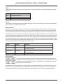
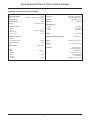
Vocia® Paging Station Kit 1 (PSKIT-1) Manual December 2013 Biamp Systems, 9300 SW Gemini Drive, Beaverton, Oregon 97008 U.S.A. (503) 641-7287 www.biamp.com IMPORTANT SAFETY INSTRUCTIONS Important Safety Instructions 1) Read these instructions. 2) Keep these instructions. 3) Heed all warnings. 4) Follow all instructions. 5) Do not use this product near water. 6) Clean only with dry cloth. 7) Do not block ventilation openings. Install in accordance with the manufacturer’s instructions. 8) Do not install near any heat sources such as radiators, heat registers, stoves, or other product (including amplifiers) that produce heat. 9) Do not defeat the safety purpose of the grounding-type plug. A grounding type plug has two blades and a third grounding prong. The third prong is provided for your safety. If the provided plug does not fit into your outlet, consult an electrician for replacement of the obsolete outlet. 10) Protect the power cord from being walked on or pinched, particularly at plugs, convenience receptacles and the point where they exit from the product. 11) Only use attachments/accessories specified by the manufacturer. 12) Use only with equipment rack, cart, stand or table designed to provide adequate mechanical strength, heat dissipation and securement to the building structure. When a cart is used, use caution when moving the cart and product combination to avoid injury from tip-over. 13) Unplug this product during lightning storms or when unused for long periods of time. 14) Refer all servicing to qualified service personnel. Servicing is required when the product has been damaged in any way, such as power-supply cord or plug is damaged, liquid has been spilled or objects have fallen into the product, the product has been exposed to rain or moisture, does not operate normally, or has been dropped. Explanation of Graphical Symbols: Lightning Bolt: Hazardous Live voltages present when this unit is in operation. Do not touch terminals marked with this symbol while the unit is connected to live power. Exclamation Point: Replace components (i.e. fuses) only with the values specified by the manufacturer. Failure to do so will compromise safe operation of this unit. Hazardous Moving Fan Blades: Remove power before servicing and keep away from moving fan blades. WARNING - To reduce the risk of fire or electric shock, do not expose these products to rain or moisture. These products must not be exposed to dripping or splashing and no objects filled with liquids, such as vases, shall be placed on these products. WARNING – 100 Volt Speaker terminals marked with the symbol these terminals requires installation by a Skilled or Instructed Person. are Hazardous Live. External wiring connected to WARNING – MAINS Powered Products employ Safety Grounding and must be connected to a MAINS socket that is properly grounded to provide a protective earthing connection. Disconnect Device - The MAINS plug is used to disconnect MAINS power and must remain readily operable. CAUTION – When POTS Telephone Interface options are provided, connections to the telecom circuits of this device must be made by qualified, trained personnel. To reduce the risk of fire, use only No. 26 AWG solid copper wire for telecom circuit connections. Intended for Installation and Service by Skilled Personnel Only: CAUTION – To reduce the Risk of Electric Shock, Installation and Service of Biamp Products should be conducted only by Skilled Persons who are Biamp Qualified Audio Installation Professionals. Do not perform any servicing other than that contained in the Operating Instructions unless you are a Skilled Person qualified to do so. Skilled Persons must disconnect AC MAINS Power before opening product. CAUTION - The Installation steps for ‘Auxiliary Power’ are for use by Skilled Personnel only and must comply with all local codes. • National Electrical Code, ANSI/NFPA 70 for United States. • Canadian Electrical Code, Part 1, CSA C22.1, Sections 2-128, 12-010(3) and 12-100 for Canada. Wall Mounting Instructions – Wall-mounted products must be securely fastened to drywall or similar surface using a minimum of 4 wood screws (2 screws for product with only two mounting holes). Alternate fasteners which may be used include Drywall Anchors, self-tapping sheet metal screws located in metal studs or wood screws extending minimum inch into wood studs. 2 2 TABLE OF CONTENTS IMPORTANT SAFETY INSTRUCTIONS . . . . . . . . . . . . . . . . . . . . . . . . . . . . . . . . . . . . . . . . . . 2 VOCIA PAGING STATION KIT (PSKIT-1) . . . . . . . . . . . . . . . . . . . . . . . . . . . . . . . . . . . . . . . . . 4 Features . . . . . . . . . . . . . . . . . . . . . . . . . . . . . . . . . . . . . . . . . . . . . . . . . . . . . . . . . . . . . . . . . . . . . . . . . . . . . . . . 4 FRONT PANEL. . . . . . . . . . . . . . . . . . . . . . . . . . . . . . . . . . . . . . . . . . . . . . . . . . . . . . . . . . . . . . 5 Setup And Use . . . . . . . . . . . . . . . . . . . . . . . . . . . . . . . . . . . . . . . . . . . . . . . . . . . . . . . . . . . . . . . . . . . . . . . . . . . Power Indicator. . . . . . . . . . . . . . . . . . . . . . . . . . . . . . . . . . . . . . . . . . . . . . . . . . . . . . . . . . . . . . . . . . . . . . . . . . . CONNECTIONS . . . . . . . . . . . . . . . . . . . . . . . . . . . . . . . . . . . . . . . . . . . . . . . . . . . . . . . . . . . . . . . . . . . . . . . . . . . . Power . . . . . . . . . . . . . . . . . . . . . . . . . . . . . . . . . . . . . . . . . . . . . . . . . . . . . . . . . . . . . . . . . . . . . . . . . . . . . . . . . . Microphone. . . . . . . . . . . . . . . . . . . . . . . . . . . . . . . . . . . . . . . . . . . . . . . . . . . . . . . . . . . . . . . . . . . . . . . . . . . . . . Ptt Input. . . . . . . . . . . . . . . . . . . . . . . . . . . . . . . . . . . . . . . . . . . . . . . . . . . . . . . . . . . . . . . . . . . . . . . . . . . . . . . . . General Purpose Inputs . . . . . . . . . . . . . . . . . . . . . . . . . . . . . . . . . . . . . . . . . . . . . . . . . . . . . . . . . . . . . . . . . . . . General Purpose Outputs. . . . . . . . . . . . . . . . . . . . . . . . . . . . . . . . . . . . . . . . . . . . . . . . . . . . . . . . . . . . . . . . . . . Rs-232. . . . . . . . . . . . . . . . . . . . . . . . . . . . . . . . . . . . . . . . . . . . . . . . . . . . . . . . . . . . . . . . . . . . . . . . . . . . . . . . . . Aux Port . . . . . . . . . . . . . . . . . . . . . . . . . . . . . . . . . . . . . . . . . . . . . . . . . . . . . . . . . . . . . . . . . . . . . . . . . . . . . . . . Cobranet Led Indication . . . . . . . . . . . . . . . . . . . . . . . . . . . . . . . . . . . . . . . . . . . . . . . . . . . . . . . . . . . . . . . . . . . . Device Id Switches. . . . . . . . . . . . . . . . . . . . . . . . . . . . . . . . . . . . . . . . . . . . . . . . . . . . . . . . . . . . . . . . . . . . . . . . 5 5 5 5 5 6 6 6 7 7 7 7 PSKIT-1 SPECIFICATIONS . . . . . . . . . . . . . . . . . . . . . . . . . . . . . . . . . . . . . . . . . . . . . . . . . . . . 8 WARRANTY . . . . . . . . . . . . . . . . . . . . . . . . . . . . . . . . . . . . . . . . . . . . . . . . . . . . . . . . . . . . . . . . 9 FCC NOTICE. . . . . . . . . . . . . . . . . . . . . . . . . . . . . . . . . . . . . . . . . . . . . . . . . . . . . . . . . . . . . . . 10 EC DECLARATION OF CONFORMITY. . . . . . . . . . . . . . . . . . . . . . . . . . . . . . . . . . . . . . . . . . 11 ROHS COMPLIANCE AND HAZARDOUS SUBSTANCE TABLE . . . . . . . . . . . . . . . . . . . . . 12 3 VOCIA PAGING STATION KIT (PSKIT-1) The PSKIT-1 is a standalone Paging Station Kit designed to allow for direct connection to third-party equipment such as fireman’s microphone stations or custom designed fire panels. The PSKIT-1 feature embedded DSP and on-board memory to support standard and advanced public address and mass notification functionalities. The PSKIT-1 can store 999 user-configurable Page Codes. Additionally, all device-specific configuration information is stored locally, which means the PSKIT-1 does not rely on a centralized controller for processing and Page routing. Thus all the processing, routing and storage functionality in a Vocia system remains decentralized. This eliminates a single point of system failure and permits redundancy to be built directly into the network. As part of a Vocia system, the PSKIT-1 meets paging requirements for facilities of all sizes. FEATURES • Up to 999 user-configurable Page Codes • Monitored microphone capability when using dual capsule Vocia microphone • 8 priority levels: 4 regular priority levels, 4 emergency priority levels • 12 General Purpose Inputs • Local digital signal processing, including gain, filters, and compressor/limiter • 3 General Purpose Outputs • Local storage of configuration data • Store and forward functionality • Local storage of default and/or custom chimes • Sturdy, surface-mounted component housing • Built-in store and forward functionality • Rotary ID switches for unit identification • CobraNet® audio/control, plus power on single cable • CE marked, UL certified and RoHS compliant • Dual/Redundant Powering (PoE, 24V DC) • Covered by Biamp Systems’ 5-year warranty • Microphone and Push-to-Talk (PTT) input • RS-232 control of functionality for third-party control systems • Support for an optional Biamp-supplied high-quality, handheld or gooseneck microphone 4 VOCIA PAGING STATION KIT (PSKIT-1) FRONT PANEL Setup and Use The Vocia software provides an intuitive interface for configuration, DSP equalization and programming of the PSKIT-1. The information supplied by this manual relates to physical connections and assignment. For more details on software setup, please consult the Vocia Help File. Power Indicator Caution - Due to potential energy hazard, connections to the Auxiliary Power 24V DC inputs must be made by a qualified electrician or other qualified person The Vocia PSKIT-1 is capable of operation from both PoE and 24V DC power. If both are being used, PoE power is given priority. The Power Indicator LED behaves in the following manner: LED Description None No power Solid green Powered CONNECTIONS Power The PSKIT-1 supports powering via 802.3af or 802.3at (Type 1) PoE switches or external PoE Supplies. Alternatively the device can be powered using the Power connector and an external 24V DC supply. Both supplies can be connected at the same time without affecting the unit. Upon loss of one power source the unit automatically switches to the other source without interrupting device operation. Microphone A microphone may be connected using the external 3-pin balanced microphone input provided. The default nominal input level is -50dBu. Phantom power is not available on this input. If using this input, the microphone and its connection will not be monitored. The PSKIT-1 also includes a 5-pin internal connector for supporting a Biamp monitored microphone (optional accessory). This connection is not accessible from the outside of the enclosure and must only be used with a Biamp supplied microphone. If the internal connector is being used with a monitored microphone, the LK1 and LK2 jumpers must be removed. By default the jumpers are installed, which disables the monitoring functionality so that a standard (3-pin) microphone may be used. Do not use both the internal and external microphone connections at the same time. 5 VOCIA PAGING STATION KIT (PSKIT-1) FRONT PANEL PTT Input The Push-to-Talk function will be activated when the PTT pin is connected to Ground. General Purpose Inputs The PSKIT-1 supports 12 unmonitored Control Inputs for connection to a keypad interface numbered 0 through 9, as well as inputs for a Next and Previous scroll button. Each Control Input is activated with a momentary connection to Ground. Only one pin can be selected at once. Pin Labeled 1 Assignment Ground 2 1 Keypad 1 3 2 Keypad 2 4 3 Keypad 3 5 4 Keypad 4 6 Ground 7 5 Keypad 5 8 6 Keypad 6 9 7 Keypad 7 10 8 Keypad 8 11 Ground 12 9 Keypad 9 13 10 Keypad 0 14 11 Next Scroll 15 12 Previous Scroll General Purpose Outputs Two General Purpose Outputs are used to indicate the Wait and Talk states. Once the PTT is active the “Wait” output will assert while the system establishes the necessary audio paths, checks for zone availability and plays the chime (if selected). The “Talk” output will assert once the audio path is live. Pin Labeled 1 Assignment Ground 2 1 Wait 3 2 <not currently in use> 4 3 Talk 5 12V 12V DC (100mA) 6 VOCIA PAGING STATION KIT (PSKIT-1) FRONT PANEL RS-232 A female RS-232 serial port is provided for Vocia Text Protocol (VTP) connectivity. Please refer to the software help file for all supported commands. Pin Out Function Pin 2 Transmit Data TXD output Pin 3 Receive Data RXD input Pin 5 GND / 0V Aux Port A RJ-45 connector is available internally for use with Biamp accessories. This port is not an Ethernet port and must not be connected to a switch, PoE supply, or other Ethernet network devices. Network Connection The PSKIT-1 is a CobraNet device and uses the RJ-45 connector for communications with other Vocia devices. It is possible to use this network connection with an 802.3af or 802.3at (type 1) PoE switch or external PoE Supplies to provide power to the device. Alternatively, if the device is being powered using the Power Connector and an external 24V DC supply, a connection to the CobraNet network must still be available for the device communications. All CobraNet routing and bundle assignments are processed by the Vocia devices locally. Vocia makes dynamic use of available bundles in CobraNet. A 100Base-T Ethernet switch (not repeater hub) is required when networking multiple units. CobraNet utilizes standard CAT5, CAT5e, CAT6, or CAT7 cabling, which has a specified maximum length of 328 feet (100 meters). Additional Ethernet switches, or switches which provide fiber-optic interface, can be used to extend the physical distance between units within a network. Please note that CobraNet limits network extensions to 7 hops (one-way transmissions) within a network. The RJ-45 connector provides two LEDs that indicate Ethernet link and network activity. Left LED Right LED Description None None No Data Connectivity or CobraNet activity. Amber Flashing green Link established and CobraNet activity detected. The unit is acting as the CobraNet Performer. Flashing amber Flashing green Link established and CobraNet activity detected. The unit is acting as the CobraNet Conductor. Flashing amber None CobraNet fault. Check cabling and configuration for errors. Device ID switches The rotary ID switches are located on the front of the unit and are used to provide a unique Device ID. The switches are in hexadecimal format. All Vocia units of the same type must have a unique Device ID to function properly within a Vocia Paging World (for instance, it is not possible to have two Vocia Devices of the same type with the same Device ID of hex 07). As an example, to assign a Device ID of hex 07, turn the LSB switch to 7 and leave the MSB switch on 0. To create an ID of hex B7, turn the LSB switch to 7 and turn the MSB switch to B. Device ID switches should be set using a 0.1 inch (2.5mm) to 0.12 inch (3.0mm) flat blade screwdriver. More information on setting IDs and the hexadecimal numbering scheme used can be found in the Vocia Software Help File. 7 VOCIA PAGING STATION KIT (PSKIT-1) SPECIFICATIONS Vocia Paging Station Kit Interface 1 SPECIFICATIONS A/D Converters: Connection: Frequency Response: +0, -1dB, 100Hz to 20kHz Effective Input Headroom: 30dB Gain: Adjustable in 1dB steps over a 30dB range System Headroom:18dB Nominal Input Level:-50dBu THD + N: <0.05% 20Hz to 8kHz PoE Power: DC Power: Overall Dimensions: Height: Width: Length: General Purpose Inputs: Quantity:12 Type: Contact Closure / TTL TTL Logic Low: 0 – 0.8V TTL Logic High: 2 – 5V General Purpose Outputs: Quantity: Max Continuous Current: Max External Supply: Weight: Ambient Operating Temperature Range: 3 200mA 40V Altitude: Humidity: Reference Output: 1.6” (40.6mm) 5.24” (133mm) 11.54” (293mm) 2.25lb (1.02kg) 32-113º F (0–45º C) 0–10,000 feet (0-3000 meters) 0% to 95% non-condensing 12V DC 100mA Compliance: RS-232: Baud: Data Bits: Parity: Stop Bits: Flow Control: 24-bit (48kHz sampling) RJ-45 with shielded Ethernet (CAT5, CAT5e, CAT6 or CAT7) 802.3at Type 1 Class 2 24V DC 6W 57600 bps 8 None 1 None 8 CE marked (Europe) RoHS Directive (Europe) UL Certified Safety E215636 (US, Canada) FCC Part 15B (USA) RCM (Australia) EAC (Eurasian Customs Union) WARRANTY BIAMP SYSTEMS IS PLEASED TO EXTEND THE FOLLOWING 5-YEAR LIMITED WARRANTY TO THE ORIGINAL PURCHASER OF THE PROFESSIONAL SOUND EQUIPMENT DESCRIBED IN THIS MANUAL 1. BIAMP Systems warrants to the original purchaser of new products that the product will be free from defects in material and workmanship for a period of 5 YEARS from the date of purchase from an authorized BIAMP Systems dealer, subject to the terms and conditions set forth below. 2 If you notify BIAMP during the warranty period that a BIAMP Systems product fails to comply with the warranty, BIAMP Systems will repair or replace, at BIAMP Systems’ option, the nonconforming product. As a condition to receiving the benefits of this warranty, you must provide BIAMP Systems with documentation that establishes that you were the original purchaser of the products. Such evidence may consist of your sales receipt from an authorized BIAMP Systems dealer. Transportation and insurance charges to and from the BIAMP Systems factory for warranty service shall be your responsibility. 3. This warranty will be VOID if the serial number has been removed or defaced; or if the product has been altered, subjected to damage, abuse or rental usage, repaired by any person not authorized by BIAMP Systems to make repairs; or installed in any manner that does not comply with BIAMP Systems’ recommendations. 4. Electro-mechanical fans, electrolytic capacitors, gooseneck microphones, cords connecting handheld microphones, hard-drives, displays, and normal wear and tear of items such as paint, knobs, handles, keypads and covers are not covered under this warranty. All server-based devices are warranted for 3 years only. 5. This warranty is in lieu of all other warranties, expressed or implied. Biamp Systems disclaims all other warranties, expressed or implied, including, but not limited to, implied warranties of merchantability and fitness for a particular purpose. 6. The remedies set forth herein shall be the purchaser’s sole and exclusive remedies with respect to any defective product. 7. No agent, employee, distributor or dealer of Biamp Systems is authorized to modify this warranty or to make additional warranties on behalf of Biamp Systems. Statements, representations or warranties made by any dealer do not constitute warranties by Biamp Systems. Biamp Systems shall not be responsible or liable for any statement, representation or warranty made by any dealer or other person. 8. No action for breach of this warranty may be commenced more than one year after the expiration of this warranty. 9. Biamp systems shall not be liable for special, indirect, incidental, or consequential damages, including lost profits or loss of use arising out of the purchase, sale, or use of the products, even if BIAMP Systems was advised of the possibility of such damages. 585.0404.90A 9 FCC COMPLIANCE FCC NOTICE - CLASS B DIGITAL DEVICE NOTE: This equipment has been tested and found to comply with the limits for a Class B digital device, pursuant to Part 15 of the FCC Rules. These limits are designed to provide reasonable protection against harmful interference in a residential as well as in a commercial installation. This equipment generates, uses and can radiate radio frequency energy and, if not installed and used in accordance with the instructions, may cause harmful interference to radio communications. However, there is no guarantee that interference will not occur in a particular installation. If this equipment does cause harmful interference to radio or television reception, which can be determined by turning the equipment off and on, the user is encouraged to try to correct the interference by one or more of the following measures: 1) Reorient or relocate the receiving antenna, 2) Increase the separation between the equipment and receiver, 3) Connect the equipment into an outlet on a circuit different from that to which the receiver is connected or 4) Consult the dealer or an experienced radio/TV technician for help. 10 COMPLIANCE DoC PSK201311 EC Declaration of Conformity Biamp Systems Corporation, as manufacturer having sole responsibility, hereby declares that our delivered version of the following described product complies with the applicable provisions of the DIRECTIVES below except as noted herein. Any alterations to the product not agreed upon and directed by Biamp Systems Corporation will invalidate this declaration. Brand Name: Vocia® Product Description: Paging Station Control Interface Model: PSKIT-1 Applicable EC Directives: Applicable Harmonized Standards: LVD Directive (2006/95/EC) Safety EN 60065:2002, A1:2006, A11:2008, A2:2010, A12:2011 EMC Directive (2004/108/EC) Emissions Immunity EN 55103-1:2009, Environment E2 EN 55103-2:2009, Environment E2 RoHS Directive (2011/65/EU) RoHS Recast Special Considerations for Product Environment or Compliance: • Use only CE marked Power over Ethernet (PoE) power supply and/or DC power supply. • Shielded cabling must be used for system connections. Technical Construction File, Location and Contact: +1 503.641.7287 +1 503.626.0281 [email protected] Biamp Systems Corporation 9300 S.W. Gemini Drive Beaverton, OR USA 97008 phone: fax: e-mail: Authorized Representative: Larry Copley, Compliance Engineer Authorized Signature: Date and Place Issued: November 2013, Beaverton, Oregon USA 12 11 COMPLIANCE RoHS Compliance and Hazardous Substance Table This Biamp product, including all attendant cables and accessories supplied by Biamp, meets all requirements of EU Directives 2011/65/EU. The information below is presented in accordance with parallel requirements of Chinese law SJ/T11363-2006. gH©£ Biamp Systems Corporation #L¤ (Announcement Station) Vocia PSKIT-1 Pb · ²7 ©W Hg Cd Cr+6 PBB w ½ $º PBDE §Ci (Equipment Chassis) X O X O O O b\RaG (Plug-in Terminal Blocks) ZM (Cable Ties) ! (CD ROM) Y':%Äco (Manual and Paper Documents) .¤:Xg.¤kd (Box and Packing Materials) O O O O O O O O O O O O O O O O O O O O O O O O O O O O O O 0£¨²Xg?©kd®gsgH© SJ/T11363-2006 À,¥v. X£¨²¡Jg?©kdX8®gsgH©Æ SJ/T11363-2006 À,¥v. >¦F:W¼½X8?©kd½3%/68³5ª 0.01%p] 91/338/EECn_p] 76/769/EECÀ,»;:m0©:,-²+Xq±ÁD >WE©X8?©kd·3%/68³5ª 0.1%: 1) G <&X8· 2) ·>¶kf6´ 8³5¬ 0.35% 3) ·>¹kf6´ 8³5¬ 0.4% 4) ·>¸kf6´ 8³5¬ 4% 5) Æd·1·d6´·8³ª 85% 6) Gò&· 7) VdX8·°aµ :TB <.¤% ·8³ª 80% 85% 8) ÅPµ°a&· 9) I«¾SV° d >rNU(=hÀ 10 Olf • A|Q 0-40C (32-104°F) • }Q 0-95%e* • z\ÆQ 0-2000- • ty4¿ • xguW%{¯"² • ~ IEEE 802.3af PoEClass 2 : 24VDC, 6W • ²xg^@^@²P1 • K2`j9[)kd¯¢Xg 13 12