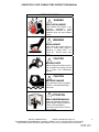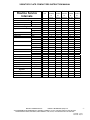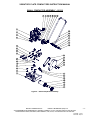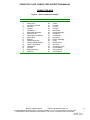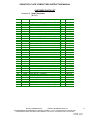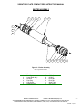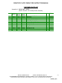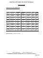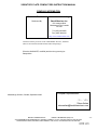
1
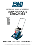
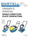
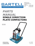
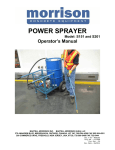
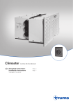
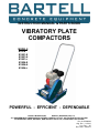
INSTRUCTION MANUAL & PARTS BOOK VIBRATORY PLATE COMPACTORS MODELS B1318 B1821-S B1821-H B1821-L B1824-S B1824-H B1824-L POWERFUL - EFFICIENT - DEPENDABLE BARTELL MORRISON INC. BARTELL MORRISON (USA) LLC 375 ANNAGEM BLVD, MISSISSAUGA, ONTARIO, CANADA, L5T 3A7, 905-364-4200 FAX 905-364-4201 25 INDUSTRIAL DRIVE, KEYPORT, NEW JERSEY, USA, 07735, 732-566-5400 FAX 732-5444 Doc. # OI-B09038 Orig. Rel. – 11/2010 Curr. Rev. – 05 Rev. Date – 06/2013 VIBRATORY PLATE COMPACTORS INSTRUCTION MANUAL SAFETY PRECAUTIONS ! DANGER EXPLOSION HAZARD Never operate the machine in an explosive atmosphere, near combustible materials or where ventilation does not clear exhaust fumes. ! WARNING BURN HAZARD Never come into contact with the engine or muffler when engine is operating or shortly after it is turned off. Serious burns may occur. ! CAUTION MOVING PARTS Before starting the machine ensure that all guards and safety devices are in place and fUNCtioning properly. ! CAUTION MACHINE DAMAGE Never operate on hard, unyielding surfaces. Unwarranted damage may result. ! ATTENTION READ OWNERS MANUAL Read and understand operator's manual before using this machine. Failure to follow operating instructions could result in serious injury or death. BARTELL MORRISON INC. BARTELL MORRISON (USA) LLC 375 ANNAGEM BLVD, MISSISSAUGA, ONTARIO, CANADA, L5T 3A7, 905-364-4200 FAX 905-364-4201 25 INDUSTRIAL DRIVE, KEYPORT, NEW JERSEY, USA, 07735, 732-566-5400 FAX 732-566-5444 -2- Created: 11/10 Revised: 06/13 VIBRATORY PLATE COMPACTORS INSTRUCTION MANUAL TABLE OF CONTENTS QUALITY ASSURANCE/MACHINE BREAK-IN .................................................................... 4 VIBRATORY PLATE COMPACTOR WARRANTY................................................................ 5 MAINTENANCE RECORD ..................................................................................................... 6 ROUTINE SERVICE INTERVALS .......................................................................................... 7 FOREWORD ........................................................................................................................... 9 SAFETY PRECAUTIONS ....................................................................................................... 9 ASSEMBLY INSTRUCTIONS ................................................................................................ 9 1. HANDLE.............................................................................................................................. 9 2. EXCITER............................................................................................................................. 9 OPERATING PRINCIBLE....................................................................................................... 9 1. STARTING PROCEDURES - WARM TEMPERATURES................................................... 9 2. STARTING PROCEDURES - COLD TEMPERATURES .................................................... 9 3. STOPPING PROCEDURES ............................................................................................... 9 OPERATION ......................................................................................................................... 10 LUBRICATION...................................................................................................................... 10 1. ENGINE OIL...................................................................................................................... 10 2. EXCITER HOUSING ......................................................................................................... 10 MAINTENANCE.................................................................................................................... 10 1. AIR CLEANER .................................................................................................................. 10 2. LUBRICATION .................................................................................................................. 10 3. SPARK PLUG ................................................................................................................... 10 4. BELT TENSION ................................................................................................................ 10 STORAGE............................................................................................................................. 10 ASSEMBLY DRAWINGS AND PARTS LIST....................................................................... 11 1. LARGE COMPACTOR ASSEMBLY (FIGURE 1) ............................................................ 12 LARGE COMPACTOR PARTS LIST ............................................................................... 14 2. SMALL COMPACTOR ASSEMBLY (FIGURE 2)............................................................. 15 SMALL COMPACTOR PARTS LIST................................................................................ 17 3. EXCITER ASSEMBLY (FIGURE 2) ................................................................................. 18 EXCITER PARTS LIST .................................................................................................... 19 TROUBLESHOOTING.......................................................................................................... 20 SPECIFICATIONS ................................................................................................................ 21 COMPANY INFORMATION.................................................................................................. 22 NOTES .................................................................................................................................. 23 BARTELL MORRISON INC. BARTELL MORRISON (USA) LLC 375 ANNAGEM BLVD, MISSISSAUGA, ONTARIO, CANADA, L5T 3A7, 905-364-4200 FAX 905-364-4201 25 INDUSTRIAL DRIVE, KEYPORT, NEW JERSEY, USA, 07735, 732-566-5400 FAX 732-566-5444 -3- Created: 11/10 Revised: 06/13 VIBRATORY PLATE COMPACTORS INSTRUCTION MANUAL QUALITY ASSURANCE / MACHINE BREAK IN The Bartell Vibratory Plate Compactor is the product of extensive engineering development designed to give long life and unmatched performance. The Compactors are shipped completely assembled with the exception of attaching the handle, and only require filling with fuel and a brief check of lubricant levels in preparation for operation. The exciter housing are pre-serviced with oil at factory. You can help ensure that your Vibratory Plate Compactor will perform at top levels by observing a simple routing on first use. Consider that your new Compactor is like a new car. Just as you would break in a new car to the road or any new machine to the job, you should start gradually and build up to full use. Learn what your machine can do and how it will respond. Refer to the engine manufacturer’s manual for run-in times. Full throttle and control may be used after this time period, as allowed by material. This will serve to further break in the machine on your specific application, as well as provide you with additional practice using the machine. We thank you for the confidence you have placed in us by purchasing a Bartell Vibratory Plate Compactor and wish you many years of satisfied use. BARTELL MORRISON INC. BARTELL MORRISON (USA) LLC 375 ANNAGEM BLVD, MISSISSAUGA, ONTARIO, CANADA, L5T 3A7, 905-364-4200 FAX 905-364-4201 25 INDUSTRIAL DRIVE, KEYPORT, NEW JERSEY, USA, 07735, 732-566-5400 FAX 732-566-5444 -4- Created: 11/10 Revised: 06/13 VIBRATORY PLATE COMPACTORS INSTRUCTION MANUAL VIBRATORY PLATE COMPACTOR WARRANTY Bartell agrees to furnish without charge, F.O.B. our plant, a replacement for any part or portion thereof, comprising the main unit of the Bartell Vibratory Plate Compactor, consisting of the exciter housing assembly, save and except drive belts, and power units, prove upon our examination, to be defective in either material or workmanship within a period of twelve (12) months from date of purchase, provided that notice of such defective part or portion thereof is given to Bartell Ltd. within the twelve month warranty period. No further or other guarantee or warranty expressed or implied in connection with the sale of the Compactor is given and our sole liability consists in replacing defective parts or portions thereof. We shall not be responsible for any special, indirect or consequential damages arising in any manner whatsoever. This guarantee is for the sole benefit of the original purchaser as end user. Our responsibility under this guarantee ends in the case the original purchaser transfers ownership of the Vibratory Plate Compactor, makes any changes or adds any parts or devices not of our manufacture to the Compactor machine. BARTELL MORRISON INC. BARTELL MORRISON (USA) LLC 375 ANNAGEM BLVD, MISSISSAUGA, ONTARIO, CANADA, L5T 3A7, 905-364-4200 FAX 905-364-4201 25 INDUSTRIAL DRIVE, KEYPORT, NEW JERSEY, USA, 07735, 732-566-5400 FAX 732-566-5444 -5- Created: 11/10 Revised: 06/13 VIBRATORY PLATE COMPACTORS INSTRUCTION MANUAL MAINTENANCE RECORD PREVENTATIVE MAINTENANCE AND ROUTINE SERVICE PLAN This Bartell Vibratory Plate Compactor has been assembled with care and will provide years of service. Preventative maintenance and routine service are essential to the long life of your Compactor Machine. Your dealer is interested in your new machine and has the desire to help you get the most value from it. After reading through this manual thoroughly, you will find that you can do some of the regular maintenance yourself. However, when in need of parts or major service be sure to see your Bartell dealer. For your convenience we have provided this space to record relevant data about your Vibratory Plate Compactor. When in need of parts or service be prepared to provide your Compactor serial number. Locate the serial number now and record in the space below. Date Purchased: Type of Machine: Dealer Name: Model: Dealer Phone: Serial Number: REPLACEMENT PARTS USED PART NO. QUANTITY COST MAINTENANCE LOG DATE DATE OPERATION BARTELL MORRISON INC. BARTELL MORRISON (USA) LLC 375 ANNAGEM BLVD, MISSISSAUGA, ONTARIO, CANADA, L5T 3A7, 905-364-4200 FAX 905-364-4201 25 INDUSTRIAL DRIVE, KEYPORT, NEW JERSEY, USA, 07735, 732-566-5400 FAX 732-566-5444 -6- Created: 11/10 Revised: 06/13 VIBRATORY PLATE COMPACTORS INSTRUCTION MANUAL Routine Service Intervals Each use After 1.5 Each 3 Each 6 Each 9 Each 12 months months months months months or or or or or 50 hrs 100 hrs 200 hrs 300 hrs 400 hrs General Inspection: Guards Warning stickers Test run: Check Check Check operation o o o o o o o o o o o o o o o o o o o o o o o o o o o o o o o o Engine: Engine oil Engine oil filter Oil cooler Cooling Fins Air cleaner Air Intake Line Fan Belt Valve clearance Fuel filter Fuel Tank Engine wiring Check Level Change Replace Clean Clean Check - clean Replace Check Replace Check tightness Replace Check-adjust Check & Clean Replace Clean Check o o o o o o o o o o o o o o o o o 2 yrs o 500 hrs o o o 500 hrs o Exciter: Exciter oil Drive belt Retardant Spray System: Water flow operation Spray nozzles Retardant Fluid Check Level Change Check tightness Change o o o Check Clean Check levels o o o o o o o o o o o o o o o o o BARTELL MORRISON INC. BARTELL MORRISON (USA) LLC 375 ANNAGEM BLVD, MISSISSAUGA, ONTARIO, CANADA, L5T 3A7, 905-364-4200 FAX 905-364-4201 25 INDUSTRIAL DRIVE, KEYPORT, NEW JERSEY, USA, 07735, 732-566-5400 FAX 732-566-5444 -7- Created: 11/10 Revised: 06/13 VIBRATORY PLATE COMPACTORS INSTRUCTION MANUAL Routine Service Intervals Due to the nature and environment of use, plate compactors could be exposed to severe operating conditions. Some general maintenance guidelines will extend the useful life of your machine. The initial service for your compactor should be performed after 25 hours of use, at which time your mechanic (or authorized repair shop) should complete all of the recommended checks in the schedule above. The chart on page 6 (six) is handy for keeping a record of the maintenance performed and the parts used for servicing your compactor. Regular service according to the schedule above will prolong the life of the plate compactor and prevent expensive repairs. Keeping your plate compactor clean and free from debris is the single most important regular maintenance operation, over and above the checks in the service schedule above, that can be performed. After each use your compactor should be cleaned to remove any dust and debris from the undercarriage and surrounding components. Use of a power washer will make clean up quick and easy, especially if a non-stick coating was applied prior to use. In the Service Schedule above, items that should be checked, replaced or adjusted are indicated by “o” in the appropriate column. Not all plate compactor models include the same features and options and as such not all service operations may have to be performed. For ease of recording place a checkmark () through the “o” when the item is complete. If an item is not required or not completed place an “x” through the “o” in the box. All compactors have governed engine speed of 3600 rpm. See engine manufacturer’s manual for exact specifications. Care should be used when making any adjustments to the compactor not to change the governed speed. Running the engine at lower rpm’s will result in a decrease of compaction force and lower travel speed. It will create excessive “out-of-synch” vibrations resulting in poor compaction, maneuverability, excessive wear to the machine, and discomfort to the operator. Failure to have your vibratory plate compactor regularly serviced and properly maintained in accordance with the manufacturer’s instructions will lead to premature failure and void the warranty. BARTELL MORRISON INC. BARTELL MORRISON (USA) LLC 375 ANNAGEM BLVD, MISSISSAUGA, ONTARIO, CANADA, L5T 3A7, 905-364-4200 FAX 905-364-4201 25 INDUSTRIAL DRIVE, KEYPORT, NEW JERSEY, USA, 07735, 732-566-5400 FAX 732-566-5444 -8- Created: 11/10 Revised: 06/13 VIBRATORY PLATE COMPACTORS INSTRUCTION MANUAL FOREWORD OPERATING PRINCIPLE The Bartell Vibratory Plate Compactor is highly effective for a wide variety of surface, sub-soil, and back-fill materials. Although relatively light in weight and easy to operate, the Vibratory Plate Compactor delivers a tremendous impact to the soil. Pound for pound, the compactors provide a higher impact force. That means more productivity from our ideal combination of speed and deeper compaction. An eccentric weight mounted on the exciter shaft contained within the exciter housing is driven at high speed by a clutch and belt drive system. This high speed shaft revolution causes the rapid lifting and downward ramming motion of the machine as well as imparting a forward motion. The plate compactor is designed to run at an engine speed (engine take off shaft) of 3600 rpm. (normally considered full throttle). Running the engine at lower rpm’s will result in a decrease of compaction force and lower travel speed. It will create excessive “out-of-synch” vibrations resulting in poor compaction, maneuverability, excessive wear to the machine, and discomfort to the operator. SAFETY PRECAUTIONS Always keep unauthorized, inexperienced, untrained people away from this machine. Rotating and moving parts will cause injury if contacted. Make sure guards are in place. Keep hands and feet away from moving parts. Fuel the machine only when the engine is stopped, using all necessary safety precautions. The engine must always be stopped before attempting any repair or adjustments. Ignition switch should be off. Danger: Never operate the machine in an explosive atmosphere, near combustible materials or where ventilation does not clear exhaust fumes. Repair fuel leaks immediately. Refer to your engine owner’s manual for more safety instructions. Be careful not to come in contact with the muffler when the engine is hot, serious burns may result! ASSEMBLY INSTRUCTIONS Your new Bartell Vibratory Plate Compactor has been shipped to you partially disassembled. Filling the fuel tank and a brief check of lubricant levels in preparation for operation is required. To complete the assembly the following instructions will be helpful. STARTING PROCEDURE: * WARM CLIMATE Open fuel valve on gas tank. Set throttle lever to “Fast” idle position, set choke to closed position, start engine. Open choke slightly to prevent flooding. Move to “Open” or “Run” position when engine is warm, increase throttle to maximum operation position (3600 rpm). STARTING PROCEDURE: * COLD CLIMATE Follow same procedure as above but allow longer warmup period – 3 to 5 minutes. In cold weather, oil is much heavier to move and requires more time to work its way into the moving parts. If maximum power is not attained, allow further warm-up time. Fill fuel tank with clean gasoline, use safety approved gas containers. DO NOT MIX OIL WITH GASOLINE – USE UNLEADED GAS ONLY. STOPPING PROCEDURE A) HANDLE – Refer to the particular final assembly diagram in this parts book that corresponds with your compactor model. Attach the one-piece handle with the screws and lock washers supplied. B) EXCITER – When installing the exciter assembly between the clamps, exciter housing should be located with an equal dimension protruding beyond the outside faces of the exciter clamps. The exciter clamp bolts must be torqued to 50 foot pounds. DO NOT EXCEED THESE RECOMMENDATIONS. Refer to the particular final assembly diagram in the parts book that corresponds with your compactor model. 1. Throttle engine down. 2. Depress or turn off stop switch. BARTELL MORRISON INC. BARTELL MORRISON (USA) LLC 375 ANNAGEM BLVD, MISSISSAUGA, ONTARIO, CANADA, L5T 3A7, 905-364-4200 FAX 905-364-4201 25 INDUSTRIAL DRIVE, KEYPORT, NEW JERSEY, USA, 07735, 732-566-5400 FAX 732-566-5444 -9- Created: 11/10 Revised: 06/13 VIBRATORY PLATE COMPACTORS INSTRUCTION MANUAL OPERATION MAINTENANCE 1. In operation, guide the machine, but let the compactor do the work. Bearing down on the handle is unnecessary and causes shock absorber wear. 2. On level surfaces the compactor moves forward rapidly. On uneven surfaces or inclines, light forward pressure on handle may be required to assist the compactor in moving forward. 3. ALWAYS OPERATE THE MACHINE AT FULL THROTTLE. If excessive vibration is felt through the handle, do not operate until the engine is checked and set at its maximum running speed of 3600 rpm. Insure the drive belt is adjusted properly. Refer to belt tension section. 4. The handle has a spring loaded locking mechanism to keep it upright in storage. DO NOT OPERATE THE MACHINE WITH THE HANDLE IN THE STORAGE POSITION. To unlock the handle, push it to the left and pull back to operation position. Maintaining your compactor will insure long life to the machine and its components. AIR CLEANER - Keep air filter clean at all times. Wash away dust and debris using a non-oil based cleaning solvent. Let the filter dry before re-installing. LUBRICATION – Always check engine oil regularly. Use proper engine oil as recommended. See chart below. Fill crankcase to levels as recommended in manufacture’s engine manual. SPARK PLUG – Check and clean spark plugs regularly. A fouled, dirty or carboned spark plug causes hard starting and poor engine performance. Set spark plug gap to recommended clearance. Refer to engine manual. BELT TENSION – IMPORTANT! If there is excessive belt play, there will be a decrease in the impact force and erratic vibration, which could cause machine damage. The normal belt play should be 1/2” to 5/8” which is attained by depressing the top section of the belt at the belt guard mounting bracket location. When adjusting the belt make sure that the clutch is in alignment with exciter pulley. Tighten all engine mount bolts, adjust the two engine-stop bolts, and tighten lock nuts. LUBRICATION ENGINE OIL Always check engine oil before starting and at regular intervals thereafter. Use proper engine oil as recommended – see chart below. Keep engine oil clean, change accordingly. Fill crankcase to levels as recommended in manufacturer’s engine manual. EXCITER HOUSING The exciter housing is pre-serviced using exactly 4 ½ oz.of EXXON (ESSO) NUTO H-32 oil or its equivalent. STORAGE The following steps should be taken to prepare your plate compactor for extended storage. 1. Close fuel shut off valve. 2. Siphon excess gasoline from tank. 3. Start engine until it stops from lack of fuel. This will use up all the fuel in the carburetor and prevent formation of deposits due to evaporation of fuel. 4. Remove spark plug and pour 2 oz. of SAE 10W-30 motor oil into the cylinder. Slowly crank the engine 2 or 3 times to distribute the oil throughout the cylinder. This will help prevent rust during storage. Replace spark plug. 5. Store the unit in an upright position in a cool, dry, well ventilated area. Season Temperature Grade of Engine Oil All Season SAE 10W-30 BARTELL MORRISON INC. BARTELL MORRISON (USA) LLC 375 ANNAGEM BLVD, MISSISSAUGA, ONTARIO, CANADA, L5T 3A7, 905-364-4200 FAX 905-364-4201 25 INDUSTRIAL DRIVE, KEYPORT, NEW JERSEY, USA, 07735, 732-566-5400 FAX 732-566-5444 - 10 - Created: 11/10 Revised: 06/13 VIBRATORY PLATE COMPACTORS INSTRUCTION MANUAL ASSEMBLY DRAWINGS AND PARTS LIST BARTELL MORRISON INC. BARTELL MORRISON (USA) LLC 375 ANNAGEM BLVD, MISSISSAUGA, ONTARIO, CANADA, L5T 3A7, 905-364-4200 FAX 905-364-4201 25 INDUSTRIAL DRIVE, KEYPORT, NEW JERSEY, USA, 07735, 732-566-5400 FAX 732-566-5444 - 11 - Created: 11/10 Revised: 06/13 VIBRATORY PLATE COMPACTORS INSTRUCTION MANUAL COMPACTOR ASSEMBLY 1 3 2 45 36 33 34 35 4 5 6 5 24 25 41 26 23 13 17 27 21 11 22 8 20 12 19 28 19 8 18 37 10 41 9 40 7 38 39 42 16 41 14 15 29 31 32 30 44 43 Figure 1 – Large Compactor Assembly Note: B1821 Compactor Shown BARTELL MORRISON INC. BARTELL MORRISON (USA) LLC 375 ANNAGEM BLVD, MISSISSAUGA, ONTARIO, CANADA, L5T 3A7, 905-364-4200 FAX 905-364-4201 25 INDUSTRIAL DRIVE, KEYPORT, NEW JERSEY, USA, 07735, 732-566-5400 FAX 732-566-5444 - 12 - Created: 11/10 Revised: 06/13 VIBRATORY PLATE COMPACTORS INSTRUCTION MANUAL COMPACTOR BOM Figure 1 – Large Compactor Assembly Item # 1 2 3 4 5 6 7 8 9 10 11 12 13 14 15 16 17 18 19 20 21 22 23 Description Engine Muffler Cap Sheet Metal Screw Hex Bolt Lock Washer Washer Base Plate Rubber Shock Mount Lock Washer Cap Screw Steel Spacer Steel Mounting Plate Disc Spring Flat Head Screw Flat Head Screw Lock Washer C/S Bridge Ass’y Slider Nut Lock Washer Hex Bolt Hex Bolt Hex Nut Steel “L” Bracket Item # 24 25 26 27 28 29 30 31 32 33 34 35 36 37 38 39 40 41 42 43 44 45 Description Hex Bolt Handle Ass’y Hex Bar Internal Lock Washer Hex Bolt Exciter Ass’y Pulley Woodruff Key Set Screw Clutch Ass’y Spacer Washer Flat Head Screw Clutch Key Belt Guard Flat Head Screw Hex Bolt Hex Bolt Washer Lock Washer Nylock Nut Belt Clutch Spacer BARTELL MORRISON INC. BARTELL MORRISON (USA) LLC 375 ANNAGEM BLVD, MISSISSAUGA, ONTARIO, CANADA, L5T 3A7, 905-364-4200 FAX 905-364-4201 25 INDUSTRIAL DRIVE, KEYPORT, NEW JERSEY, USA, 07735, 732-566-5400 FAX 732-566-5444 - 13 - Created: 11/10 Revised: 06/13 VIBRATORY PLATE COMPACTORS INSTRUCTION MANUAL CUSTOMER PARTS LIST Assembly # Large Compactor (Low/High Speed) (B1821, B1824) Item # B1821 B1824 Description 1 2 3 4 5 6 7 8 9 10 11 12 13 14 15 16 17 18 19 20 21 22 23 24 25 26 27 28 29 30 30 31 32 33 34 35 36 37 38 39 40 41 42 43 44 45 46 * 21357 11112 11115 30008 10402 10905 30072 30007 30005 30012 30020 30035 30053 30013 30033 30004 30067 30037 10009 30019 30001 10108 30036 30142 30065 30017 30003 30015 30076 14284 30130 10609 50117 30202 30042 11256 30032 30167 10843 30181 13312 10919 10902 10317 30195 11254 30190 30074 21357 11112 11115 30008 10402 10905 30066 30007 30005 30012 30020 30035 30053 30013 30033 30004 30067 30037 10009 30019 30001 10108 30036 30142 30065 30017 30003 30015 30076 14284 30130 10609 50117 30202 30042 11256 30032 30167 10843 30181 13312 10919 10902 10317 30195 11254 30190 30074 Honda Engine, 5.5hp, GX160 Muffler Cap GX160 HH Self Tap ¼" x 3/8"LG HHCS 5/16-18 UNC x 1-3/4” Lock Washer, 5/16" Washer, 3/8 Narrow Base Plate Ass'y Rubber Shock Mounts 1/2-13 Nut Lock Washer, 1/2" Hi-Collar SHCS, 1/2-20 UNF x 3" LG 2" OD x 3/4" LG Spacer 5/16 x 2" x 6" MTG Plate Disc Spring 3/4"ID FHCS 1/2-13 UNC x 3/4" FHCS 1/2-13 UNC x 1" Lock Washer 1/2" C/S Bridge Ass'y Slider Nut, 5/8” x 5/8” x 3-3/4” Lock Washer, 1/2" HHCS 1/2-13 UNC x 1-1/2" HHCS 5/16-18 UNC x 2” Hex Nut, 5/16-18 UNC Positive Stop HHCS 5/16-18 UNC - 3/4" Handle Tube Handle Pin Lock Washer 1/2"ID Internal HHCS 1/2-13 UNC x 3/4” Exciter Ass'y Pulley BC, 42” x 1-1/4”, 1 pc, L & S Models Pulley BC, 38” x 1-1/4”, 2 pc, H Models Woodruff Key (1010) 1"dia x 5/16"thk SHSS, 5/16-18 x 0.57” UNC, Cup Point Clutch Assy (Compactor) Retainer Washer, 1-1/4"OD x .125"THK FHSCS 5/16-24 UNF x 1" Clutch Key 3/16"SQ x 2"LG Belt Guard Comp LG FHCS 3/8-18 UNC x 1-1/4" HHCS 3/8-16 UNC x 3/4" HHCS 3/8-16 UNC x 1-1/4" Flat Washer, 5/16" Dia. Lock Washer 3/8” Nylock Nut 3/8-16UNC Belt - AX 34 Clutch Spacer Clutch Spring (not shown) Allen Key Qty Eff. Date 1 1 3 4 14 2 1 8 2 2 4 2 2 4 2 6 1 2 12 4 2 2 1 10 1 2 2 8 1 1 1 1 3 1 1 1 1 1 1 1 1 4 1 1 1 1 1 1 12/02/04 12/02/04 12/02/04 12/02/04 12/02/04 12/02/04 11/20/07 12/02/04 12/02/04 12/02/04 12/02/04 12/02/04 12/02/04 12/02/04 12/02/04 12/02/04 12/02/04 12/02/04 12/02/04 12/02/04 12/02/04 12/02/04 12/02/04 12/02/04 12/02/04 12/02/04 12/02/04 12/02/04 12/02/04 12/02/04 12/02/04 12/02/04 12/02/04 12/02/04 12/02/04 12/02/04 12/02/04 12/02/04 12/02/04 12/02/04 12/02/04 12/02/04 12/02/04 12/02/04 12/02/04 7/12/05 12/02/04 12/02/04 BARTELL MORRISON INC. BARTELL MORRISON (USA) LLC 375 ANNAGEM BLVD, MISSISSAUGA, ONTARIO, CANADA, L5T 3A7, 905-364-4200 FAX 905-364-4201 25 INDUSTRIAL DRIVE, KEYPORT, NEW JERSEY, USA, 07735, 732-566-5400 FAX 732-566-5444 - 14 - Created: 11/10 Revised: 06/13 VIBRATORY PLATE COMPACTORS INSTRUCTION MANUAL SMALL COMPACTOR ASSEMBLY – B1318 Figure 2 – Small Compactor Assembly BARTELL MORRISON INC. BARTELL MORRISON (USA) LLC 375 ANNAGEM BLVD, MISSISSAUGA, ONTARIO, CANADA, L5T 3A7, 905-364-4200 FAX 905-364-4201 25 INDUSTRIAL DRIVE, KEYPORT, NEW JERSEY, USA, 07735, 732-566-5400 FAX 732-566-5444 - 15 - Created: 11/10 Revised: 06/13 VIBRATORY PLATE COMPACTORS INSTRUCTION MANUAL COMPACTOR BOM Figure 2 – Small Compactor Assembly Item # 1 2 3 4 5 6 7 8 9 10 11 12 13 14 15 16 17 18 Description Honda Muffler Cap Self Tapping Screw Hex Bolt Locknut Flatwasher Base Plate Assembly Rubber Mount High Collar Lockwasher Socket Bolt Bushing Handle Hinge Cap Rubber Handle Bushing Water Tank Bracket Lockwasher Hex Bolt Bridge Assembly Slider Nut Item # 19 20 21 22 23 24 25 26 27 28 29 30 31 32 33 34 35 36 Description Washer V-Belt Hex Bolt Locknut Hex Bolt Belt Guard Handle Assembly Handle Pin Lockwasher Clutch Key Excitor Assembly Pulley Woodruff Key Set Screw Compactor Clutch Clutch Washer Flat Head Bolt Clutch Spacer BARTELL MORRISON INC. BARTELL MORRISON (USA) LLC 375 ANNAGEM BLVD, MISSISSAUGA, ONTARIO, CANADA, L5T 3A7, 905-364-4200 FAX 905-364-4201 25 INDUSTRIAL DRIVE, KEYPORT, NEW JERSEY, USA, 07735, 732-566-5400 FAX 732-566-5444 - 16 - Created: 11/10 Revised: 06/13 VIBRATORY PLATE COMPACTORS INSTRUCTION MANUAL CUSTOMER PARTS LIST Assembly # Small Compactor (B1318) Item # Part # Description Qty Eff. Date 1 2 3 4 5 6 7 8 9 10 11 12 13 14 15 16 17 18 19 20 21 22 23 24 25 26 27 28 29 30 31 32 33 34 35 36 21340 11112 11115 30008 10402 10919 30106 30007 30005 30012 30120 30121 30122 30192 10009 30015 30133 30037 11043 30203 30001 10108 30031 30132 30123 30017 10521 30032 30129 14284 10609 50117 30202 30042 30041 11254 Honda GX120 4HP Muffler Cap - #18340-ZE1-010 #8 Self Tapping Bolt HHCS 5/16 - 18 x 1-3/4 Locknut 5/16" Flatwasher 5/16"Dia Base Plate Assembly - 13" x 18" Rubber Mounts 1/2-13UNC Lockwasher, High Collar 1/2" SHCS 1/2-20UNF x 3"LG Bushing Handle Hinge Cap Rubber Handle Bushing Water Tank Bracket Lockwasher 1/2" HHCS 1/2-13 x 3/4"LG Bridge Assembly Slider Nut, 5/16-18UNC Washer 1/4" V-Belt AX30 HHCS 5/16-18 x 2"LG Locknut 5/16-18 UNC HHCS 1/4-20 UNC x 1/2"LG Belt Guard Handle Tube Handle Pin Lockwasher, 1/4"Dia Clutch Key, 3/16” x 3/16” x 2”LG (GX120/160) Excitor Assembly Pulley BC 42 x 1-1/4"Bore Woodruff Key # 808 SHSS Cup Pt. 5/16-18UNC x 1/2"LG Compactor Clutch Clutch Washer FHSCS 5/16-24 x 3/4"LG Clutch Spacer 1 1 3 4 4 2 1 4 2 2 2 4 2 1 10 10 1 2 2 1 3 3 3 1 1 2 3 1 1 1 1 3 1 1 1 1 12/02/04 12/02/04 12/02/04 12/02/04 12/02/04 12/02/04 12/02/04 12/02/04 12/02/04 12/02/04 12/02/04 12/02/04 12/02/04 12/02/04 12/02/04 12/02/04 09/27/07 12/02/04 12/02/04 12/02/04 12/02/04 12/02/04 12/02/04 12/02/04 12/02/04 12/02/04 12/02/04 12/02/04 12/02/04 09/27/07 12/02/04 12/02/04 12/02/04 12/02/04 12/02/04 7/12/05 BARTELL MORRISON INC. BARTELL MORRISON (USA) LLC 375 ANNAGEM BLVD, MISSISSAUGA, ONTARIO, CANADA, L5T 3A7, 905-364-4200 FAX 905-364-4201 25 INDUSTRIAL DRIVE, KEYPORT, NEW JERSEY, USA, 07735, 732-566-5400 FAX 732-566-5444 - 17 - Created: 11/10 Revised: 06/13 VIBRATORY PLATE COMPACTORS INSTRUCTION MANUAL EXCITER ASSEMBLY 6 7 10 1 11 12 5 8 4 2 1 9 7 6 3 8 5 Figure 3 – Exciter Assembly Note: Large Exciter Shown. Item # 1 2 3 4 5 6 Description Bearing Large Shaft Ass’y Oil Seal Pipe Plug Cap Screw Retaining Ring Item # 7 8 9 10 11 12 Description O-Ring O-Ring End Cap End Cap Steel Tube Set Screw BARTELL MORRISON INC. BARTELL MORRISON (USA) LLC 375 ANNAGEM BLVD, MISSISSAUGA, ONTARIO, CANADA, L5T 3A7, 905-364-4200 FAX 905-364-4201 25 INDUSTRIAL DRIVE, KEYPORT, NEW JERSEY, USA, 07735, 732-566-5400 FAX 732-566-5444 - 18 - Created: 11/10 Revised: 06/13 VIBRATORY PLATE COMPACTORS INSTRUCTION MANUAL CUSTOMER PARTS LIST Assembly # 30129, 30077, 30076 (Small, S-model, L & H model) Exciter Assembly Item # 1 2 3 4 5 6 7 8 9 10 11 12 B1318 30047 30164 10610 10911 30010 30016 30027 30028 30044 30045 30125 10987 S Model 30047 30163 10610 10911 30010 30016 30027 30028 30044 30045 30025 10987 L&H Model 30047 30162 10610 10911 30010 30016 30027 30028 30044 30045 30025 10987 Description Bearing #NJ308EG1C3 Shaft Ass’y Oil Seal Pipe Plug, Sq. Hd.,3/8-18 SHCS 1/4-20 x 1/2 UNC Retaining Ring, N5000-400 O-Ring, #224, Fluorocarbon O-Ring, #224, Fluorocarbon Flange End Cap Mechanical Tube Dowel Pin, 3/16”Dia. x 1/2”LG Qty Eff. Date 2 1 1 1 4 2 4 4 1 1 1 2 12/02/04 12/02/04 12/02/04 12/02/04 12/02/04 12/02/04 12/02/04 12/02/04 12/02/04 12/02/04 12/02/04 12/02/04 BARTELL MORRISON INC. BARTELL MORRISON (USA) LLC 375 ANNAGEM BLVD, MISSISSAUGA, ONTARIO, CANADA, L5T 3A7, 905-364-4200 FAX 905-364-4201 25 INDUSTRIAL DRIVE, KEYPORT, NEW JERSEY, USA, 07735, 732-566-5400 FAX 732-566-5444 - 19 - Created: 11/10 Revised: 06/13 VIBRATORY PLATE COMPACTORS INSTRUCTION MANUAL TROUBLESHOOTING WON’T START Throttle fully open Hand lever wire broken No gas Dirty gas Gas filter plugged Gas line plugged Hole in gas line Gas supply valve turned off Safety switch wire or connectors not making good contact Other engine problems (Refer to engine manual) BELT WEARING RAPIDLY Belt adjusted improperly Pulley out of alignment Wrong belt/defective belt Clutch sticking STARTS BUT NO HIGH SPEED Engine problems Throttle cable broken or seized Throttle lever and connectors loose or out of adjustment Clutch shoes worn WON’T MOVE FORWARD OR REVERSE Exciter spinning too slow or not at all Debris on the undercarriage of the exciter base MACHINE JUMPS ON FLOOR Surface too hard, unyielding Warped or damaged compactor base OIL LEAKS Exciter End-cap seals worn or damaged Mainshaft seal worn Damaged bearing Too much oil in exciter housing EXCITER SHAFT WILL NOT TURN Bearing(s) seized Shaft keys broken Belt damaged Engine rpm’s too low BARTELL MORRISON INC. BARTELL MORRISON (USA) LLC 375 ANNAGEM BLVD, MISSISSAUGA, ONTARIO, CANADA, L5T 3A7, 905-364-4200 FAX 905-364-4201 25 INDUSTRIAL DRIVE, KEYPORT, NEW JERSEY, USA, 07735, 732-566-5400 FAX 732-566-5444 - 20 - Created: 11/10 Revised: 06/13 VIBRATORY PLATE COMPACTORS INSTRUCTION MANUAL SPECIFICATIONS VIBRATORY PLATE COMPACTOR Model Plate Size Centrifugal Force Cycles per Minute Travel Speed Engine Operating Weight B1318 13" x 18" (33 x 46cm) 2000 lbs. 909 kg 5040 110 ft/min. 34 m/min. Honda 4 HP 138 lbs. 63 kg B1821-S 18" x 21" (46 x 53cm) 2450 lbs. 1114 kg 5040 91 ft/min. 28 m/min. Honda 5.5 HP 184 lbs. 84 kg B1821-L 18" x 21" (46 x 53cm) 2800 lbs. 1273 kg 5040 93 ft/min. 28.5 m/min. Honda 5.5 HP 186 lbs. 85 kg B1821-H 18" x 21" (46 x 53cm) 3600 lbs. 1636 kg 5800 110 ft/min. 34 m/min. Honda 5.5 HP 187 lbs. 85 kg B1824-S 18" x 24" (46 x 61cm) 2450 lbs. 1114 kg 5040 89 ft/min. 27 m/min. Honda 5.5 HP 193 lbs. 88 kg B1824-L 18" x 24" (46 x 61cm) 2800 lbs. 1273 kg 5040 91 ft/min. 28 m/min. Honda 5.5 HP 195 lbs. 88 kg B1824-H 18" x 24" (46 x 61cm) 3600 lbs. 1636 kg 5800 110 ft/min. 34 m/min. Honda 5.5 HP 196 lbs. 89 kg Optional Equipment: Self-drip Spray System BARTELL MORRISON INC. BARTELL MORRISON (USA) LLC 375 ANNAGEM BLVD, MISSISSAUGA, ONTARIO, CANADA, L5T 3A7, 905-364-4200 FAX 905-364-4201 25 INDUSTRIAL DRIVE, KEYPORT, NEW JERSEY, USA, 07735, 732-566-5400 FAX 732-566-5444 - 21 - Created: 11/10 Revised: 06/13 VIBRATORY PLATE COMPACTORS INSTRUCTION MANUAL COMPANY INFORMATION Worldwide Distribution International Marketing Distributed By: Bartell Morrison Inc. 375 Annagem Blvd. Mississauga, ON, Canada L5T 3A7 Tel: (905) 364-4200 Fax: (905) 364-4201 http://www.bartellmorrison.com Conforms with the provisions of the “MACHINES” directive, modified (directive 89/392/CEE) and the national codes transposing it. (Directive 89/392/CEE, modified) and the rules governing its transposition Mississauga, Ontario, Canada, September 2009 European Representative Steve Adam Steve Adam [email protected] BARTELL MORRISON INC. BARTELL MORRISON (USA) LLC 375 ANNAGEM BLVD, MISSISSAUGA, ONTARIO, CANADA, L5T 3A7, 905-364-4200 FAX 905-364-4201 25 INDUSTRIAL DRIVE, KEYPORT, NEW JERSEY, USA, 07735, 732-566-5400 FAX 732-566-5444 - 22 - Created: 11/10 Revised: 06/13 VIBRATORY PLATE COMPACTORS INSTRUCTION MANUAL NOTES BARTELL MORRISON INC. BARTELL MORRISON (USA) LLC 375 ANNAGEM BLVD, MISSISSAUGA, ONTARIO, CANADA, L5T 3A7, 905-364-4200 FAX 905-364-4201 25 INDUSTRIAL DRIVE, KEYPORT, NEW JERSEY, USA, 07735, 732-566-5400 FAX 732-566-5444 - 23 - Created: 11/10 Revised: 06/13