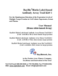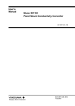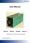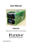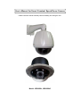
1
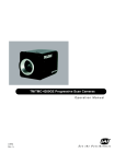
User’s Manual for Smart Constant Speed Dome Camera
Please read the manual carefully before installing and using the unit.
Model: JE900BN, JE900BNC
Table of Contents
PART I: INTRODUCTION.......................................................................................................................................2
1-1 INSTRUCTIONS:........................................................................... 2
1-2 CHARACTERISTICS ..................................................................... 2
1-3 MAIN TECHNICAL DATA ............................................................. 3
PART II: INSTALLATION PROCEDURES...........................................................................................................4
2-1 OUTER SHAPE AND INSTALLATION SIZE ....................................... 4
2-2 INSTALLATION OF DOME COVER................................................. 4
2-3 HOUSING AND WALL-MOUNT BRACKET INSTALLATION ............. 5
2-4 INSTALLATION OF THE BRACKET ................................................ 5
2-5 POWER SUPPLY ADAPTER INSTALLATION ..................................... 6
2-6 INSTALLATION FOR EMBEDDED DOME CAMERA ......................... 7
2-7 COMPLETE ELECTRICAL WIRED SKETCH ..................................... 7
2-8 RUNNING STATE TEST ................................................................. 8
PART III: SETUP AND OPERATE..........................................................................................................................8
3-1 PROTOCOL, BAUD RATE, ADDRESS AND SPEED SETUP ................ 8
3-3 THE PARTICULAR COMMAND AND ITS DEFINITION .................... 11
3-4 SET UP AND PREVIEW PRESET POSITIONS ................................. 11
1-5 SETUP AND RUNNING OF TOUR GROUP ...................................... 12
3-6 SETUP AND SCAN BETWEEN TWO POINTS .................................. 13
3.6.1
Setup of Left/right Limiting Positions ...........................................................................................14
3.6.2
Start scanning between two points ..............................................................................................14
3-7 START 360° SCANNING FUNCTION OF THE PAN/TILT ................. 14
3-8 STOP THE AUTO SCANNING ....................................................... 15
3-9 THE SETUP, ACTIVATING AND EXITING OF DEFAULT POSITION . 15
PART IV: APPENDIX.............................................................................................................................................16
PART V. CONNECTING SKETCH ......................................................................................................................17
1
Part I: Introduction
1-1 Instructions:
We greatly appreciate your choosing our product!
The product is under one year warranty, including free maintenance or spare parts replacement. Do not
dismantle and repair the unit without the company’s authorization.
Damage or breakdown arising from the following circumstances is No free maintenance:
1. dismantling and repairing of the unit without the company’s authorization;
2. the transportation, loading or unloading of the unit which is arranged by the customer;
3. using and maintenance of the unit without observing the instructions in the User’s Manual, including
damage or breakdown arising from crashing, crushing, and unit affected with damp, liquids,
corrosive or other man-made causes;
4. inapplicable ambient temperature or overloaded operation; surface abrasion or damage emerging
when the unit is being used;
5. natural disasters and other accidents.
Attention: To realize all the functions of the unit, a compatibility test must be carried out before applying
other manufacturer’s spare parts in the system.
1-2 Characteristics
1. Precise conductive slip-ring is adopted, which 360°pan endless running and all-direction monitoring
is realized, and cable-twisting problem with common constant speed domes are effectively solved.
2. The operation is based on advanced stepper motors and driving circuits, which ensures smooth
running, long time consecutive working, long lifespan and high reliability.
3. PCB board is very concise, most of the parts on the PCB board are highly integrated and modulated,
thus the malfunction is greatly reduced and the stability of the performance is ensured.
4. The design of the outer housing is reasonable, elegant and practical. It can endure long-term operation
without distortion. And the installation is fast and convenient.
5. The function of Position Limiting is realized with photoelectrical sensors, which avoids traditional
disadvantage of mechanical and switch Position Limiting (the switch lifespan is 200,000 times
ON/OFF).
6. Left/right limiting positions can be set up by the key of the camera panel, it also can be set up through
our company’s keyboard, which avoids the limitations that it can only be set up from the front
terminals.
7. There are 4 levels of running speed optional for the unit: 6°, 9°, 12°,15°/S, which can be adjusted
according to actual conditions.
8. The built-in PCB panel supports multi mainstream protocols, which can be input according to the
customer’s needs. The Baud rate is also adjustable.
9. The unit adopts DC14V(15V) power supply and separates from it the components that produce heat
in the process of transformation, which prolongs the durability of the unit. The unit is anti-jamming
and anti-crashing.
10. Two grades anti-lightening technology, which effectively improve the anti-lightening and
2
anti-interruption ability
11. If the power is off when the unit is scanning or cruising, it will automatically resume scanning or
cruising once power supply is on.
12. Support 16 preset positions, 1 tour, left & right scan, 360° scan.
13. The unit has one guard position; the user can preset it for a key monitor area according to the actual
conditions. If not operated after 5 minutes, it will automatically monitor the preset position.
DC14V---15V
Dome motor
DC14V---15V/0.5A
Camera lens motor
DC12V/100mA
Camera power supply
12V/1A
Electric
Heater & fan working range
Fan(≥50°C); heater (≤5°C)
Addresses range
Communication system
Communication protocol
Baud rate
Controlling device
Preset position quantity
Auto Scan
Tour group quantity
Default position function
Dome movement
1~63
RS485 bus controlling
Pelco-D, Pelco-P, Pelco-D1
1200bps, 2400bps, 4800bps, 9600bps
video matrix, DVR controlling keyboard
16 preset positions
Scan between two points and 360° endless scan
1 group(16 preset positions can be included)
Yes
pan 360° endless, tilt 0°-90°
Mechanical
Dome speed
6º/S, 9º/S, 15º/S, 20º/S adjustable
Movement limiting position
pan adjustable within the dome movement scope
Ambient temperature
0ºC~49ºC (without temperature controlling devices)
-40ºC~60ºC (with temperature controlling devices)
Relative Humidity
≤95%RH
Image Sensor
1/4〞Super Had CCD
Resolution
480TV Line
Lens
f=3.25-88mm High Durability 27X Zoom Lens
Angle of View
48 degrees (w) Horizontal 3 degrees (t)
Sync System
Internal/Line Lock NTSC 60 Hz , PAL 50HzC
Minimum illumination
0.5Lux/0.1Lux with B/W mode
IR Sensitive
0Lux with IR on
Video Focus
Auto/Manual (Near-Far)
White Balance
Auto/OFF
BLC
Auto/OFF
Electric shutter
1/50~1/12000s
S/N Ratio
>50dB
Video Output
Composite 1.0+/-0.2Vp-p
Camera
Power supply
Ambient
1-3 Main Technical Data
2A
3
Part II: Installation Procedures
2-1 Outer shape and installation size
1, JE900BN
2, JE900BNC
2-2 Installation of Dome Cover
1, JE900BN
2, JE900BNC
For model JE900BN, Put the dome cover to the housing well in right position, then tighten the two
screws manually or with a screwdriver. (See the above figure at left)
For Model JE900BNC embedded dome, Fit the three plastic pegs on the dome cover to the
corresponding ones on the housing, then turn it to the right for about 20 degrees till it stops moving. (See
the above figure at right)
4
2-3 Housing and Wall-mount Bracket installation
Push the power, video and controlling integrated cable through the bracket hole, then direct the top of the
housing to the bracket hole and tighten them. Use a screwdriver to drive the three M6 screws on the
bracket into the screw slot. (See the above figure)
2-4 Installation of the Bracket
2-5 Wall-mount installation
Figure 1: Dimension of the installing bottom board of the Wall Bracket for Outdoor Dome Camera
Select the where you want to installing and make sure the place can be sustained its weight.
Pencil the relative positions of the four φ7.5 bores of the wall bracket on the wall, and fix the
bracket on the wall with particular screws (prepared by the user). (See the above figure)
2-6 Ceiling installation
Figure 2: Dimension of Pole Bracket
5
Select the where you want to installing and make sure the place can be sustained its weight. Pencil
the relative positions of the three bores of the bracket on the ceiling, and fix the bracket to the
ceiling with special screws (prepared by the user). Do not forget to push the connecting power,
video and controlling cables through the cable outlet into the bracket tube in advance.
Special Instruction: Pole bracket is used for indoor installation. In some special condition if it is needed to
be used outdoors, in order to prevent the rain water from seeping into the unit and affecting the normal
running, please pay attention to the following points in the installation project:
1. The diameter of the flange on the outdoor vertical pole should be at least 20cm more than that of the
installing flange of the Pole bracket.
2. The cable should not go through the cable-slot on the flange edge of the Pole bracket, it should go
through the central hole of the bracket.
3. The 3 bolts fixing position should be sealed with sealant to prevent the rain water from seeping in.
2-5 Power supply adapter installation
To make sure the power source is at DC15V 2A for the PTZ camera, you’d better to install the AC/DC
power adapter inside the arm bracket or next to the PTZ camera to avoid the drop of voltage, due to there is
a big internal resistor in the DC circuit.
¾
Step 1
Put the power adaptor into the well connected wall bracket and pin the power adaptor with the power
pinning board lest the power adaptor slides out. (See the above figure)
¾
Step 2
Pull the power, video and controlling integrated cable out of the bracket tube via the cable out-going slot,
then fit the dotted-line part of the bracket shown in the figure to the two corresponding pegs on the installed
peg-board, then push the bracket downward until it locks in place. Make sure the bracket fits well with the
bracket installing bottom board, then tighten the Tightening Screw on the bracket. (See the above figure)
6
2-6 Installation for Embedded dome Camera
Locations with suspended top suit the dome camera with in-ceiling installation style, which appears to be
a hemisphere, having elegant-look and good concealment. The in-ceiling style installation applies to solid
locations of the ceiling. First, select the desired location, pencil the outline of the upper housing on the ceiling
and make a corresponding-size bore(about 210mm diameters for Seven-inch Dome Camera, about 240mm
diameters for Nine-inch one), then insert the upper housing into the ceiling, and press the spring pinning
boards against the edge of the ceiling opening. After that, tighten the screw adjusting the spring pinning
boards, and lock the upper housing in the ceiling tightly. For the sake of better safety, please use a metal wire
rope to connect the top of the upper housing to a reinforced structure of the ceiling. (The wire rope is required
to bear at least 5 times the weight of the dome camera.)
2-7 Complete electrical wired sketch
Note:
1, RS485 white cable is for RS485-, RS485 Green Cable is for RS485+
7
2-8 Running state test
When you installed the dome camera and make sure the connecting is correct, you can power it on with
the power supply DC14V (15V) for camera running state test.
Once the power it on, check whether the power indicator led on the PCB board is on. Now the dome
camera should be running self-check – panning, tilting and zooming. After the self-check, the position of the
dome is horizontally on the left limiting position, tilt 30º. This means the PTZ camera is in good condition.
Two abnormal states may follow the self-check:
a. The dome camera makes no action
b. The dome camera is in the state of pan auto-scanning
If the dome camera is in the state of pan auto-scanning, the scanning should be stopped through the
controlling device to avoid possible friction or collision between camera cable and inner housing caused by
inappropriate installation of the camera.
After installing the dome cover, control the dome camera to make slow pan/tilt movement, and observe
its agility and stability, and check whether there is friction or collision between camera, cable and inner
housing.
If the camera movement is unstable and with noise, please check whether the connection between the
speed dome and the bracket is vertical, or whether the camera is in good connection with the peg-board. If not,
switch off the power supply, then check and re-install the unit following the above-mentioned installation
instructions.
If there is friction or collision between the camera, cable and the inner housing, switch off the power and
open the vitreous cover to adjust the position of the camera on the suspender, or tidy up the cables inside the
inner housing. Then reinstall the vitreous cover.
Switch on the power again, control the dome camera to make slow pan/tilt movement, observe its agility
and stability, and check whether there is friction or collision between camera, cable and inner housing.
As per the method introduced above, adjust the unit well.
Part III: Setup and Operate
3-1 Protocol, Baud Rate, Address and Speed setup
It is important to setup the protocol, baud rate and camera address for controlling, Both of the dome
camera and controller must be setting same in the protocol, baud rate and camera address
8
1. Address Setup
As shown in the figure below, DIP-1 to DIP-8 of the 10-button coding switches is used to set up address
of the dome camera from 1 to 63. Control can be realized only when address code of the dome camera is
identical to that of the hard disk video recorder or matrix or controlling keyboard. The coding switches from
DIP-1 to DIP-8 are equivalent to a 8-bit binary figure. The state “ON” of each bit means “1”
while”OFF”means”0”. Table 2 shows states of coding switches
The table of Camera ID:
9
No.
12345678
No.
12345678
No.
12345678
No.
12345678
1
10000000
17
10001000
33
10000100
49
10001100
2
01000000
18
01001000
34
01000100
50
01001100
3
11000000
19
11001000
35
11000100
51
11001100
4
00100000
20
00101000
36
00100100
52
00101100
5
10100000
21
10101000
37
10100100
53
10101100
6
01100000
22
01101000
38
01100100
54
01101100
7
11100000
23
11101000
39
11100100
55
11101100
8
00010000
24
00011000
40
00010100
56
00011100
9
10010000
25
10011000
41
10010100
57
10011100
10
01010000
26
01011000
42
01010100
58
01011100
11
11010000
27
11011000
43
11010100
59
11011100
12
00110000
28
00111000
44
00110100
60
00111100
13
10110000
29
10111000
45
10110100
61
10111100
14
01110000
30
01111000
46
01110100
62
01111100
15
11110000
31
11111000
47
11110100
63
11111100
16
00001000
32
00000100
48
00001100
64
00000010
Table 3:Camera Address and Coding Switches
The camera ID can be 255, please ask us for more details about the ID setting if you need
2. Communication Baud Rate Setup
As shown in the above figure, DIP-9 and DIP-10 of the 8-button coding switches are used to set up Baud
rate of communication and 4 different Baud rate can be selected (1200BPS/2400BPS/4800BPS/ 9600BPS).
Following table shows states of coding switches of baud rate. The state “ON” of each bit means “1”, while
“OFF” means “0”.
No.
1200 bps
2400 bps
4800 bps
9600 bps
No. 9
OFF
ON
OFF
ON
No. 10
OFF
OFF
ON
ON
3. Protocol Setup
As indicated in the above figure, DIP-1 to DIP-4 of the 6-button coding switches are used to set up
protocol of the dome camera. The built-in Decoding PCB Board provides protocols as listed in Table 6. Other
protocols can also be written-in as the user requires.
No.
DIP- 4,3,2,1
Types of Protocols
1
0000
PELCO_D
2
0001
PELCO_P
3
1110
JCO
4
1111
PELCO_D1
4. Set up the Movement Speed
The movement speed of the dome can be set up through the coding switch.
DIP 5 and DIP6 of the 6-button coding switch (see figure above) are used to set up the movement speed of the
dome. Please refer details as Table 6.
No.
DIP: 5 6
Pan speed
1
00
6°
2
10
9°
3
01
15°
4
11
20°
10
3-3 The particular command and its Definition
The below table is the particular short command for operate the PTZ camera with protocol “Pelco-D” and
“Pelco-P”
These short commands are useful for operation the PTZ function. Please remember
Code No.
Definition
Code No.
Definition
160
begin with left/right limiting position
setup
140
Begin with the tour group setup
161
Finish left/right limiting position setup
141
Finish the tour group setup
130
Set up left limiting position
142
Start Tour Group
131
Set up right limiting position
162
Activate Home Position function
132
Start left/right scanning
163
Disable Home Position function
135
Start 360°scanning of the pan/tilt
164
Set up Home Position
138
Stop auto scanning of the pan/tilt
The below table is the particular short command for operate the PTZ camera with protocol “Pelco-D1”
Code No
Definition
Code No
Definition
120
begin with left/right limiting position
setup
110
Begin with the tour setup
121
Finish left/right limiting position setup
111
Finish the tour setup
100
Set up left limiting position
112
Start Tour
101
Set up right limiting position
122
Activate Home Position function
102
Start left/right scanning
123
Disable Home Position function
105
Start 360°scanning of the pan/tilt
124
Set up Home Position
108
Stop auto scanning of the pan/tilt
For all kinds of operations introduced in the following paragraphs, if PELCO-D1 protocol is chosen for the
control, please choose the Function Codes inside the bracket to operate.
3-4 Set up and Preview Preset Positions
The function of preset positions works in this way: the dome camera saves the current pan/tilt parameters
in number order (1-16), quickly previews those parameters when needed, and adjust the dome to the
corresponding positions. Users can use such devices as controlling keyboard to save and preview preset
positions fast and conveniently. The dome camera can support 16 preset positions.
A. Set up preset positions
After controlling (pan/tilt) the dome camera to the position you want to monitor keyboard, enter the
number for representing the preset position and press the “PRESET” key, then you have set up the preset
position successfully.
Example: Set up preset position No.1
a. Use the joystick to move the dome camera to the desired position.
b. Enter “1”
11
c.
Press the “PRESET” key
B. Preview Preset Positions
The function enables the dome camera to quickly return to the preset position you set.
Enter the number you need to preview, Press the “PREVIEW” key, then the dome camera returns to the
preset position.
Example: Preview Preset position No.1
a. Enter “1”
b. Press the “PREVIEW” key
1-5 Setup and running of Tour group
Automatic tour function is a latest function of the constant-speed dome camera. The user can program the
preset positions into the automatic tour in the required order, when necessary, run the tour, the constant-speed
12
dome camera will automatically scan the preset positions set in the tour consecutively and circularly. Up to 16
preset positions can be saved in one tour group.
A. Setup of Tours
a.
In the keyboard initial state, enter number “140”(110) and press the “PREVIEW” key to enter
the tour setup.
b. After entering the setup, add preset position number to the tour. Enter the preset position
number and press the “PREVIEW” key, the first preset position is successfully added. Then
goes the second one. Enter the second preset position number and press the “PREVIEW” key,
the second preset position is successfully added. Up to 16 preset positions can be added in the
same way.
c. After all the required preset positions having been added in the tour, enter the number
“141”(111) and press the “PREVIEW” key to exit the tour setup.
B. Start Running a Tour
In the keyboard initial state, enter number “142” (112) and press the “PREVIEW” key to start
running the preset tour.
Example: Set up the tour order to be 1→2→5→3→4→6 (please set up preset positions before tour setup)
1. Enter number “140”(110) and Key “PREVIEW” for beginning setup
2. Enter number “1”and key “PREVIEW”, the position “1” is added in the tour group as first tour
position
3. Enter number “2”and key “PREVIEW”, the position “2” is added in the tour group as second tour
position
4. Enter number “5”and key “PREVIEW”, the position “5” is added in the tour group as third tour
position
5. Enter number “3”and key “PREVIEW”, the position “3” is added in the tour group as fourth tour
position
6. Enter number “4”and key “PREVIEW”, the position “4” is added in the tour group as fifth tour
position
7. Enter number “6”and key “PREVIEW”, the position “6” is added in the tour group as sixth tour
position
8. Enter number “141”(111) and key “PREVIEW” to exit tour setup)
9. Enter 142(112) and key “PREVIEW” to start running the tour, the dome camera will runs in order of
1→2→5→3→4→6.
3-6 Setup and scan between two points
The speed dome camera has Left/Right scanning function. The user can set up the left and right limiting
positions for the scanning area requested. When running the left/right scan, the unit will scan forwards and
backwards between the left and right limiting positions consecutively.
13
3.6.1 Setup of Left/right Limiting Positions
The user can freely set one beginning position as Left Limiting Position and one terminal position as
Right Limiting Position. (Remark: If the beginning position and the terminal position is the same position, the
speed dome will scan for 360°). The Left/right limiting positions can be set up with keyboard controller.
1.1 Enter the number “160” (120) and press “PREVIEW” key to function the setup of left/right
limiting positions
1.2 Control the dome camera by joystick, moves it to the right direction and reaches the desired
point as a right limiting position, then enter 131(101), and press “PREVIEW” key, now the
dome’s right limiting position has been set up successfully. Next, move camera to the left
direction and reaches the desired point as a left limiting position, then enter 130(100) and press
“PREVIEW” key again, now the left limiting position have been set up successfully..
1.3 enter 161(121) and press “PREVIEW” key to exit the setup. Now the setup of left/right limiting
positions is completed.
3.6.2 Start scanning between two points
Enter 132(102) and press “PREVIEW” key
3-7 Start 360° scanning function of the Pan/Tilt
The Camera can be 360° endless horizontal scanning. The operation is as below:
a, enter 135 and key “preview for 360 degree endless cruising
b, enter 95 and key “preview for 355 degree back and forth cruising
14
3-8 Stop the auto scanning
While the camera is carrying out auto scanning, if you want to stop the auto scanning, you can enter 138
(108) and press “PREVIEW” key or press “zoom+” “zoom-“ key to stop
3-9 The Setup, Activating and Exiting of Default Position
The unit has a default position. The user can set up default position for a key monitoring area according to
actual requirement. If not operated after 5 minutes, the dome camera will automatically monitor the default
position.
1.
Setup of the Default Position
Move the dome camera to a key monitoring area by joystick, enter number “164” (124) on the
keyboard and press the “PREVIEW” key, then the setup is successful.
2.
Activate and Exit the Default Position function
The user can activate or exit the function of default position through the keyboard. Enter number
“162” (122) and press the “PREVIEW” key, the function is activated. Enter number “163” (123) and
press the “PREVIEW” key, the function is exited.
15
Part IV: Appendix
Simple troubles and corresponding solutions
Problems
No action, no picture, indicator
not on when power is switched
on.
Normal self-check and image
but out of control
Abnormal self-check image
with motor noise
Unstable image
Some dome camera out of
control or control delayed
Possible causes
Soluition
Wrong connection of power cables
Correct
Power supply damaged
Replace
Not required power type
Replace
Bad power cable connection
Correct
Address or Baud rate setup wrong
Set up again
Protocol setup wrong
Set up again
RS485 bus connection wrong
Check RS485 bus connection
Mechanical failure
Repair
Camera inclined
Reinstall
Power supply not enough
Replace, placing the adaptor
nearby the unit is recommended
Bad connection of video
Correct
Power supply not enough
Replace
Power supply not enough
Replace, placing the adaptor
nearby the unit is recommended
Matching resistor is not equipped in the
dome camera at the farthest end
Install matching resistor in the
dome camera
Weak 485 signal; not enough power in
485 transformer
Replace
controlling
transformer
with
cable.
thicker
Replace
16
PART V. CONNECTING SKETCH
Technical Support: [email protected]
17