1
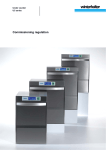
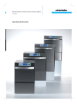
Winterhalter under counter
dishwashing machines
UC Series
Repair manual
Table of contents
Introduction-------------------------------------------------------------------1
Drawings----------------------------------------------------------------------2
Rotary or alternating current? -------------------------------------------3
Menu-driven first start-up -------------------------------------------------5
Repair instructions ---------------------------------------------------------7
Safety notes---------------------------------------------------------------7
Exchange collector ------------------------------------------------------8
Exchange boiler heating element---------------------------------- 14
Exchange boiler -------------------------------------------------------- 16
Exchange the pressure transmitter of the boiler --------------- 18
Exchange tank heating element ----------------------------------- 20
Exchange pump head (dosing device Fluidos)----------------- 22
Exchange dosing device Fluidos ---------------------------------- 24
Exchange integrated water softener ------------------------------ 26
Exchange heat exchanger / radial fan ---------------------------- 30
Flow schema--------------------------------------------------------------- 34
Model: Standard (not for UK, Australia) -------------------------- 34
Model: Standard (for UK, Australia) ------------------------------- 35
Model: integrated water softener ---------------------------------- 36
Model: Energy ---------------------------------------------------------- 37
Model: Energy / integrated water softener----------------------- 38
Options of the water treatment ---------------------------------------- 39
UC with integrated water softener --------------------------------- 39
UC with upstream water softener ---------------------------------- 39
UC with upstream desalination------------------------------------- 40
UC with upstream reverse osmosis ------------------------------- 40
UC with upstream reverse osmosis ------------------------------- 41
Requirements for a good cleaning result --------------------------- 42
Factor chemicals------------------------------------------------------- 42
Factor mechanics------------------------------------------------------ 43
Factor time -------------------------------------------------------------- 43
Factor temperature ---------------------------------------------------- 43
Introduction
The machines of the UC Series are no longer distinguished by their
intended use but by their size.
The machine name is derived from the size:
UC-S replacing GS 202, 402
UC-M replacing GS 215
UC-L replacing GS 302, GS 310
UC-XL replacing GS 315
IMPORTANT: A machine of the UC Series can be used as glass,
dishes, bistro or cutlery washing machine in any size.
The programming is carried out at the first start-up and can be changed
anytime.
Alternatively, the machines are already programmed at the factory but
can be re-programmed on site.
Main dimensions of the 4 machines
1
Height
Width
Depth
Passage
height
2
Rack size
UC-S
725-760
460
603
309
UC-M
725-760
600
603
309
UC-L
820-855
600
603
404
UC-XL
820-855
600
637
404
400x400
500x500
500x500
500x500
500x540
Dimensions in mm
1
In the machines with integrated exhaust air heat recovery (Energy) the
dimension of the height increases by 85 mm
2
Racks are not contained in the basic equipment of the machine
1
Drawings
UC-S
UC-M
UC-L
UC-XL
UC-S Energy / UC-M Energy
UC-L Energy; UC-XL Energy
a
By removing the feet the machine height is reduced by 10 mm.
UC-S; UC-M; UC-L
b
UC-XL
Without integrated containers for detergent and rinse aid the depth of
all machines is reduced by 20 mm
2
Rotary or alternating current?
The machine can be connected both to rotary and alternating current. If
the machine is put to another location, the design of rotary or alternating
current can be changed anytime.
On site (at the customer’s site) the following operations must be carried
out:
1.
2.
3.
4.
Switching the boiler heating element
( page 3)
Install and connect the appropriate mains connection cable
( page 4)
Connection to the supply and return system on site (water,
wastewater, current); according to the operating instructions
Adjust parameter P555 (locking device)
( page 4)
Switching the boiler heating element
The performance of the boiler heating
element is determined by the switching of
bridges.
The switching of the bridges must match
the electrical supply and the fusing.
The bridges are located in the plinth of
the machine.
Please see the connection scheme on
the back of the stiffener wall to the
electric installation compartment how the
bridges must be switched.
3
Install and connect the mains connection cable
Requirements to the mains connection cable
1. Use a cable of the type H07 RN-F or equivalent
2. Section and number of wires appropriate for voltage, fusing and
overall connection value
Strain relief
UC-M, UC-L, UC-XL
Tighten the screwed cable connection in the electric installation
compartment
UC-S
Tighten the screwed cable connection at the backside of the machine
Adjust parameter P555
See the connection scheme on the back of the stiffener wall to the
electric installation compartment which value must be set for parameter
P555.
Setting range: 0, 1, 2 or 3
Setting 0:
no locking
Setting 1:
Boiler heating element locks against tank heating
element
Setting 2:
Circulating pump or boiler heating element locked
against tank heating element
Setting 3:
Circulating pump and boiler heating element locked
against tank heating element
4
Menu-driven first start-up
Shortened version
The detailed description can be found in the commissioning regulation
of the UC Series.
Select language
Enter PIN 1925
Save the basic parameter set P 000 = x
Basic parameter set P 000
Mains
network
3N~;
3(N)~;
3~
1N~
dishes
rinse process
UC-M, -L, -XL
UC-S
Dishes
Standard
0001
0030
Glass
Standard
ReTemp
Cool
0006
0007
0008
0035
0036
0037
Standard
0011
0040
Standard
0013
0042
Dishes
Standard
0015
0044
Glass
Standard
ReTemp
Cool
0020
0021
0022
0049
0050
0051
dishes and
glass (Bistro)
Standard
0025
0054
dishes and
glass (Bistro)
Cutlery
5
Save addresses for service and chemicals
Enter date of day, time and date of first
start-up
Summary of the changed parameters
Switch on the machine
6
Repair instructions
Exchange collector --------------------------------------------------page 8
Exchange boiler heating element --------------------------------page 14
Exchange boiler ------------------------------------------------------page 16
Exchange the pressure transmitter of the boiler--------------page 18
Exchange tank heating element----------------------------------page 20
Exchange pump head (dosing device Fluidos) ---------------page 22
Exchange dosing device Fluidos---------------------------------page 24
Exchange integrated water softener ----------------------------page 26
Exchange heat exchanger / radial fan --------------------------page 30
The repair instructions are described for machines with integrated
chemical containers for detergent and rinse aid.
Safety notes
Danger
Warning
DANGER! Danger of life due to components that
are energised!
Disconnect the machine during all electrical work
from the mains and check if it is free of voltage.
When handling chemicals, observe the safety
notes and dosing recommendations printed on
the packing.
Wear protective clothing, protective gloves and
goggles when handling chemicals.
7
Exchange collector
8
Procedures
Required material:
Tool:
Important note:
Note for UC-S
Kit collector
Item no. 30 000 169
no special tool required
The machine must be de-installed and put
onto the left side
The procedures also apply for the UC-S.
However, it is not required to de-install the
boiler
Observe the safety notes on page 7
Remove the front panel
Pull the suction pipes out of the chemical containers
Put the suction pipes into a measuring cup with water
Successively activate the dosing devices in the actor programme
in order to rinse them with water
Drain the tank
Switch the machine free of voltage
Open the machine door
Remove lower rotating wash field, strainer and filter bottom
Dry tank with a sponge cloth
De-install the machine
Remove the right side panel
Remove the right stiffener wall
Pull off the pressure hoses off the dosing devices
Remove the left stiffener wall together with the dosing devices
Unplug and de-install the drain pump
Remove reinforcing brackets
Completely drain boiler
9
Exchange collector (continuation)
10
Procedures (continuation)
Disconnect boiler heating element
Remove the hose at the back of the boiler
Pull off the thermo sensor that is located on the boiler
Put the machine onto the left side
Remove the base cover
Pull off the two black hoses on the air chamber (air trap) of the
boiler
Put the boiler onto the machine
Unplug the diffusion sensor
Move the wire hose clip that is located at the hose of the lower
distributor upwards
On the collector, pull off the hose that leads to the Mediamat
11
Exchange collector (continuation)
12
Procedures (continuation)
Unplug the circulating pump
Pull off the waste water hose that is connected to the upper
distributor
Loosen clamp at the collector; do not remove it
Unscrew the collector and take it out
Disconnect the circulating pump of the collector
Attach a new o-ring seal
Installation of the new collector
The installation is carried out in reverse order. At the same time a new
pump wheel is to be installed. The pump wheel has a left-handed
thread.
After the assembly:
Carry out a function test
Ventilate the dosing devices
Carry out a safety test according to VDE 0701
13
Exchange boiler heating element
14
Procedures
Required material:
Tool:
Note for UC-S
Kit heating element 4.9KW with fuse
Item no.
Kit heating element 6.5KW with fuse
item no. 30 000 124 (Japan, Australia)
no special tool required
The following manual applies for the
UC-M; -L; -XL. In models of the UC-S
Series the boiler is located behind the rear
panel and can be accessed easily
Observe the safety notes on page 7
UC-M, UC-L, UC-XL
Remove the front panel
Pull the suction pipes out of the chemical containers
Remove the right stiffener wall
Completely drain boiler
Disconnect the main power cable of the boiler heating element
Unscrew 3 hexagonal nuts
Pull out the boiler heating element
If necessary, clean boiler on the inside
Replace the existing o-ring seal by a new one
Install the new boiler heating element
Connect the main power cable
Wires 1-3 connected to the gate at 2, 4, 6
Wires 4-6 connected to the clips X1-4, -5, -6
green-yellow wire connected to a grounding clip
Install the stiffener wall
Put the suction pipes into the chemical containers
Install the front panel
Carry out a function test
Ventilate the dosing devices
Carry out a safety test according to VDE 0701
15
Exchange boiler
16
Procedures
Required material:
Tool:
Important note:
Kit boiler
UC-S: Item no. 30 000 119
UC-M; -L; -XL Item no. 30 000 120
no special tool required
The machine must be de-installed
The following manual applies for the UC-M; -L; -XL. In models of the
UC-S Series the boiler is located behind the rear panel and is well
accessible.
Observe the safety notes on page 7
Remove the right side panel
Remove the front panel
Pull the suction pipes out of the chemical containers
Remove the right stiffener wall
Completely drain boiler
Remove the hose at the back of the boiler
Pull off the thermo sensor that is located on the boiler
Unscrew the boiler
Remove the hoses at the top and front of the boiler
Unscrew the heating element
Do not disconnect the heating element
Pull out the old boiler and install the new one
Use a new o-ring seal
Again tighten the heating element
Again fix the hoses
Install the stiffener wall
Put the suction pipes into the chemical containers
Install the front panel
Carry out a function test
Ventilate the dosing devices
Carry out a safety test according to VDE 0701
17
Exchange the pressure transmitter of the boiler
The following manual applies for the UC-M; -L; -XL. In models of the
UC-S Series the boiler is located behind the rear panel and is well
accessible.
18
Procedures
Required material:
Tool:
Pressure transmitter
Item no. 31 24 044
no special tool required
Observe the safety notes on page 7
Remove the right side panel
Pull forward the upper cover plate
Pull off the bus cable that is attached to the Master
Pull off the grounding cable; remove the cover plate
Pull off the transparent hose at the air chamber (air trap)
De-install the pressure transmitter of the boiler (green sticker)
with hose
Install new pressure transmitter with new hose
Mark the new pressure transmitter with a waterproof pen so that it
is different from the pressure transmitter of the tank
Install the cover plate
Plug the bus cable into the Master
Plug the grounding cable
Install the right side panel
Carry out a function test
Carry out a safety test according to VDE 0701
19
Exchange tank heating element
20
Procedures
Required material:
Tool:
Kit high power heating cartridge 1.8KW
Item no. 30 000 122
Kit high power heating cartridge 2.5KW
Item no. 30 000 123 (Cool)
no special tool required
Observe the safety notes on page 7
Drain the tank
Remove the rear panel
Unplug the cable of the tank heating element
De-install the tank heating element
Install tank heating element with new o-ring seal
Plug the cable of the tank heating element
Install the rear panel
Carry out a function test
Carry out a safety test according to VDE 0701
21
Exchange pump head (dosing device Fluidos)
22
Procedures
Required material:
Tool:
Pump head for Fluidos DT (detergent)
Item no. 31 02 599
Pump head for Fluidos DT (rinse aid)
Item no. 31 02 600
no special tool required
The following steps refer to the detergent dosing device Fluidos DT.
However, they also apply for repairs at the rinse aid dosing device
Fluidos DB.
Observe the safety notes on page 7
Remove the front panel
Pull the suction pipes out of the chemical containers
Put the suction pipes into a measuring cup with water
Activate the dosing device in the actor programme in order to
rinse it with water
Remove the right stiffener wall
Pull off suction and pressure hose at the dosing device
Unscrew 4 screws (Torx T15)
Rotate the pump head anti-clockwise by 90° and take it off
Install new pump head
Fix the suction and pressure hose at the pump head
Install the stiffener wall
Put the suction pipes into the chemical containers
Install the front panel
Carry out a function test
Ventilate the dosing devices
23
Exchange dosing device Fluidos
24
Procedures
Required material:
Tool:
Kit Fluidos DT (detergent)
Item no. 31 02 597
Kit Fluidos DB (rinse aid)
Item no. 31 02 598
no special tool required
The following steps refer to the detergent dosing device Fluidos DT.
However, they also apply for the exchange of the rinse aid dosing
device Fluidos DB.
Observe the safety notes on page 7
Remove the front panel
Pull the suction pipes out of the chemical containers
Put the suction pipes into a measuring cup with water
Activate the dosing device in the actor programme in order to
rinse it with water
Remove the right stiffener wall
Pull off suction and pressure hose at the dosing device
Remove the left stiffener wall
Unscrew the dosing device
Fix new dosing device at the stiffener wall
Fluidos DT: Adjust the setting screw to MAX
Fluidos DB: Adjust the setting screw to MIN
Fix the suction and pressure hose at the pump head
Install both stiffener walls
Put the suction pipes into the chemical containers
Install the front panel
Carry out a function test
Ventilate the dosing devices
Carry out a safety test according to VDE 0701
25
Exchange integrated water softener
26
Procedures
Required material:
Tool:
Important note:
Note for UC-S
Kit softener
Item no. 83000420
Item no. 83000421 (Japan)
Ring wrench 60003376
The machine must be de-installed
The procedures also apply for the UC-S.
However, it is not required to de-install the
boiler
Observe the safety notes on page 7
Remove the front panel
Pull the suction pipes out of the chemical containers
Put the suction pipes into a measuring cup with water
Successively activate the dosing devices in the actor programme
in order to rinse them with water
Drain the tank
Switch the machine free of voltage
De-install the machine
Remove the right side panel
Remove the right stiffener wall
Completely drain boiler
Remove the left stiffener wall together with the dosing devices
Pull off the pressure hoses off the dosing devices
Pull off the plug of the dosing devices
Pull off the thermo sensor of the tank
Unplug and de-install the drain pump
27
Exchange integrated water softener (continuation)
28
Procedures (continuation)
Unscrew the terminal block and grounding cable
De-install right flute of the strike plate
Sideways, unscrew the boiler with the terminal block out of the
machine
Open the machine door
Remove lower rotating wash field
Unscrew the fastening nut of the water softener
Pull off all cables and hoses at the water softener
Take the water softener out of the machine
Installation of the new water softener
The installation is carried out in reverse order. At the same time use a
new o-ring seal.
After the assembly:
Carry out a function test
Ventilate the dosing devices
Carry out a safety test according to VDE 0701
29
Exchange heat exchanger / radial fan
30
Procedures
Required material:
Tool:
Important note:
Kit heat exchanger
Item no. 30 000 190 and / or
Kit radial fan
Item no. 30 000 189
Ring wrench 60003376
The machine must be de-installed
Observe the safety notes on page 7
De-install the machine
Pull forward the upper cover plate
Pull off the bus cable that is attached to the Master
Pull off the grounding cable; remove the cover plate
Pull off the hoses on the right of the heat exchanger
On the riser, pull off the hose attached to the heat exchanger
Pull off the plug on the motor
Unscrew the fastening of the motor
Unscrew the fastening nut of the heat exchanger
Lift the heat exchanger with motor and turn it
31
Exchange heat exchanger / radial fan (continuation)
32
Procedures (continuation)
Cut through the belts on the intake socket and remove the hose
Installation of the new heat exchanger (item no. 30 000 190)
Disconnect heat exchanger and radial fan of each other
Fix the new heat exchanger with new seal on the radial fan
Installation of a new radial fan (item no. 30 000 189)
Disconnect heat exchanger and radial fan of each other
Remove the intake socket on the radial fan
Fix the intake socket with new o-ring seal on the new radial fan
Fix the heat exchanger with new seal on the radial fan
Installation of the complete unit
Apply a new o-ring seal
The installation is carried out in reverse order. The hose (picture 7) must
be fixed with 2 cable ties to the intake socket.
After the assembly:
Carry out a function test
Carry out a safety test according to VDE 0701
33
Flow schema
Model: Standard (not for UK, Australia)
2
4
3
5
1
1: Solenoid valve (4 l/min); cold or warm water
2: Backflow protection type "BPD"
3: Boiler
4: Rinsing pump
5: Rinse aid dosing
34
Model: Standard (for UK, Australia)
2
4
3
5
1
1: Solenoid valve (4 l/min); cold or warm water
2: Backflow protection type "Airgap"
3: Boiler
4: Rinsing pump
5: Rinse aid dosing
35
Model: integrated water softener
2
3
5
4
6
7
1
1: Solenoid valve (4 l/min); cold or warm water
2: Backflow protection type "Airgap"
3: Water softener
4: Boiler
5: Rinsing pump
6: Rinse aid dosing
7: Waste water
36
Model: Energy
3
2
5
4
6
1
1: Solenoid valve (3 l/min); cold water
2: Backflow protection type "Airgap"
3: Heat exchanger
4: Boiler
5: Rinsing pump
6: Rinse aid dosing
37
Model: Energy / integrated water softener
4
2
3
6
5
7
8
1
1: Solenoid valve (3 l/min); cold water
2: Backflow protection type "Airgap"
3: Water softener
4: Heat exchanger
5: Boiler
6: Rinsing pump
7: Rinse aid dosing
8: Waste water
38
Options of the water treatment
UC with integrated water softener
1
2
Water supply
max. 60°C
Total hardness: max. 30 °dH
Copper concentr.: max. 2 mg/l
3
Set parameter:
P503 = 2
P505: max. 30
UC
1: Water shut-off valve
2: Dirt trap (included in delivery of the UC)
3: Dishwashing machine UC Series
UC with upstream water softener
(MonoMatik / DuoMatik)
1
2
3
M/D
4
UC
with MonoMatik:
Water supply: max. 50 °C
Total hardness: max. 40 °dH
Copper concentr.: max. 2 mg/l
with DuoMatik
Water supply: max. 60°C
Total hardness: max. 40 °dH
Copper concentr.: max. 2 mg/l
Set parameter:
P503 = 0
1: Water shut-off valve
2: Dirt trap (included in delivery of the UC)
3: MonoMatik or DuoMatik
4: Dishwashing machine UC Series
39
UC with upstream desalination
(TE 15 / TE 20 / VE 15 / VE 20)
1
2
3
4
T/V
Set parameter:
P503 = 1
P511: max. 999 (99.9 m³)
UC
1: Water shut-off valve
2: Dirt trap (included in delivery of the UC)
3: TE 15 / TE 20 (partial desalination); VE 15 / VE 20 (complete
desalination)
4: Dishwashing machine UC Series
UC with upstream reverse osmosis
(RoMatik 150)
1
2
3
4
Fe
A
5
D
1: Water shut-off valve
2: Dirt trap (included in delivery of the UC)
3: Desalination filter (optional)
4: Activated carbon filter (optional)
5: Water softener DuoMatik (optional)
6: RoMatik 150 (reverse osmosis)
7: Dishwashing machine UC Series
40
6
R150
7
UC
UC with upstream reverse osmosis
(RoMatik 160, 210, 420)
1
2
3
4
Fe
A
5
D
6
R
7
UC
1: Water shut-off valve
2: Dirt trap (included in delivery of the UC)
3: Desalination filter (optional)
4: Activated carbon filter (optional)
5: Water softener DuoMatik (optional)
6: RoMatik 160 / RoMatik 210 / RoMatik 420 (reverse osmosis)
7: Dishwashing machine UC Series
41
Requirements for a good cleaning result
The "Sinner circle” describes the effective impacts in the cleaning
process. These can be divided into 4 factors:
Temperature
Time
Chemicals
Mechanics
Orient yourself to the 4 factors of the “Sinner circle” when you are
looking for the cause of a bad cleaning result.
Factor chemicals
Possible causes for a bad cleaning result are:
1. The detergent does not match the purpose
2. The rinse aid does not match the purpose
3. Dosing amount (detergent / rinse aid) too low
4. Dosing device (detergent / rinse aid) does not work (electrically /
mechanically)
5. Dosing hose (bended, not ventilated, torn, crystallised detergent)
6. Storage container (detergent / rinse aid) empty or interchanged
7. Detergent crystallised in storage container
42
Factor mechanics
Possible causes for a bad cleaning result are:
1. Contaminated or clogged nozzles
2. Contaminated or clogged filter system
3. Wrongly set parameters (e.g. too low pump pressure)
4. Blocked or worn pump wheel
5. Wrong choice of rack
6. Inadequate loading of rack
7. Foam formation (e.g. due to the use of manual washing-up liquid)
Factor time
Possible causes for a bad cleaning result are:
1. Wrong programme selected
2. Wrongly set parameters
Factor temperature
Possible causes for a bad cleaning result are:
1. Defective heating element in the tank or boiler
2. Wrongly set parameters
3. Defective temperature sensor on the tank or boiler
Additionally, the water quality plays an essential role when a perfect
cleaning result is intended to be reached. The kind of water treatment
must be adapted to the dishes ( pages 39 to 41).
43
44
Winterhalter Gastronom GmbH
Commercial Dishwashing Systems
Tettnanger Strasse 72
88074 Meckenbeuren · Germany
Telephone +49 (0) 75 42 4 02-0
Telefax +49 (0) 75 42 4 02-1 87
en ; Subject to technical alterations
89012679-00/06-09
www.winterhalter.biz
[email protected]