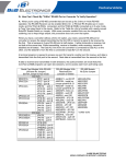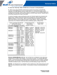
1
This manual covers the following B&B Electronics’ model serial cards: Four Port, Any Address, Any IRQ RS-232/422/485 Serial Card CE Model 3PXCC4A Documentation Number 3PXCC4A3001 Each of these models is an RS-232 serial card and uses the same printed circuit board. The "1" and "2" suffix designates the number of ports on the card. The model number of the card is printed on a sticker on the board. This product designed and manufactured in Ottawa, Illinois USA of domestic and imported parts by International Headquarters B&B Electronics Mfg. Co. Inc. 707 Dayton Road -- P.O. Box 1040 -- Ottawa, IL 61350 USA Phone (815) 433-5100 -- General Fax (815) 433-5105 Home Page: www.bb-elec.com Sales e-mail: [email protected] -- Fax (815) 433-5109 Technical Support e-mail: [email protected] -- Fax (815) 433-5104 European Headquarters B&B Electronics Ltd. Westlink Commercial Park, Oranmore, Co. Galway, Ireland Phone +353 91-792444 -- Fax +353 91-792445 Home Page: www.bb-europe.com Sales e-mail: [email protected] Technical Support e-mail: [email protected] B&B Electronics -- Revised August 2001 Manual Document# 3PXCC4A3001 Cover Page B&B Electronics Mfg Co – 707 Dayton Rd - PO Box 1040 - Ottawa IL 61350 - Ph 815-433-5100 - Fax 815-433-5104 B&B Electronics Ltd – Westlink Comm. Pk – Oranmore, Galway, Ireland – Ph +353 91-792444 – Fax +353 91-792445 Table of Contents Chapter 1: Introduction and General Information ...........1 Features .................................................................................1 Specifications .........................................................................2 Chapter 2: Quick Installation Guide ..................................3 Chapter 3: Windows Installation .......................................5 Checking Device Manager for Available Address/IRQ’s (Windows 95/98) ....................................................................5 Adding Serial Port(s) in Windows 95/98 8 Changing COM Port Resources in Windows 95/98 13 Checking Windows NT Diagnostics for Available Address/IRQ’s (Windows NT 4.0) ........................................16 Checking Windows 2000 for Available Address/IRQ’s ........19 Adding Serial Port(s) in Windows 2000 24 Chapter 4: Address and IRQ Setting ...............................31 Address Switch Setup ..........................................................31 Interrupt Jumper Setup ........................................................34 Shared IRQ Mode ................................................................35 Chapter 5: Communication Jumper Settings.................36 RS-232 Mode .......................................................................36 RS-422 Mode .......................................................................36 RS-485 Mode .......................................................................37 RS-485 Operation..........................................................37 RS-422 and RS-485 Termination.........................................38 High Speed Mode ................................................................38 Chapter 6: Physical Hook-up and Troubleshooting ......39 Pinouts .................................................................................39 RS-232 Pinouts..............................................................39 RS-422 Pinouts..............................................................40 RS-485 Pinouts..............................................................40 Communication Cable Data .................................................41 Troubleshooting ...................................................................42 Appendix A: Hardware I/O Map...................................... A-1 Appendix B: Declaration of Conformity Statement .....B-1 Manual Document# 3PXCC4A3001 Table of Contents i B&B Electronics Mfg Co – 707 Dayton Rd - PO Box 1040 - Ottawa IL 61350 - Ph 815-433-5100 - Fax 815-433-5104 B&B Electronics Ltd – Westlink Comm. Pk – Oranmore, Galway, Ireland – Ph +353 91-792444 – Fax +353 91-792445 Chapter 1: Introduction and General Information The B&B Electronics’ 3PXCC4A series serial interface cards are designed for the IBM PC, XT, AT and compatibles. Ports are configured as a standard DTE device, and connections are made on RJ45 style connectors. The 3PXCC4A cards offer exceptional setup flexibility. The 3PXCC4A series has the ability to use any I/O address and any hardware interrupt. You can install as many serial ports as will physically fit in a machine. To use one of the “non-standard” addresses or interrupts, the serial software used must also offer that flexibility. If you are writing your own application, be sure the communications routines used support any address and IRQ. B&B Electronics’ SimpCom Communications Drivers support these features. Features Each port independently configurable for any hex address 0 to hex 3F8 including COM1 – COM4 Each port independently configurable for any interrupt: 2, 3, 4, 5, 6, 7, 10, 11, 12, 14, and 15 Shared IRQ capability with Interrpt Status Register Each port independently configurable for RS-232/RS-422 or RS-485 Jumper selectable interrupts: 2, 3, 4, 5, 6, 7, 10, 11, 12, 14, and 15 Enhanced 16 bit Address Decoding Baud rates up to 460.8K baud in RS-422/RS-485 Mode, 115.2K baud in RS-232 Mode 16550A UARTs on all ports RS-232 mode supports lines: TD, RD, RTS, CTS, DSR, DCD, and DTR RS-422/RS-485 mode supports lines: TD and RD RTS control of RS-485 driver enable Can be wired for half or full duplex RS-485 communications Manual Document# 3PXCC4A3001 1 B&B Electronics Mfg Co – 707 Dayton Rd - PO Box 1040 - Ottawa IL 61350 - Ph 815-433-5100 - Fax 815-433-5104 B&B Electronics Ltd – Westlink Comm. Pk – Oranmore, Galway, Ireland – Ph +353 91-792444 – Fax +353 91-792445 Specifications Bus: IBM PC ISA Bus Slot: Requires 1 full length slot for complete IRQ selectability. When installed in a short slot, IRQ’s 10-15 will not be available. Dimensions: 7.1 x 4.3 in (18 x 10.9cm) I/O connection: RJ45 (8 conductor) connectors for all four ports Character length: 5, 6, 7, or 8 bits Parity: Even, odd or none Stop bits: 1, 1.5, or 2 RS-232 Drivers: Device: 75185 Transceiver High level output voltage: 6.0 V minimum Low level output voltage: -6.0 V minimum Output current limited to ±10 mA RS-232 Receivers: Device: 75185 Transceiver Input high threshold voltage: 1.5V Input low threshold voltage: 0.75V Device will withstand ±30V RS-422/485 Driver/Receiver: Device: 75ALS180 Differential driver output voltage: 1.5 - 6 V Differential input high-threshold voltage: 0.2 V Differential input low-threshold voltage: -0.2 V Power Consumption: RS-422/485 Mode without termination on drivers +5V, 175mA, 875mW +12V, 60mA, 720mW -12V, 60mA, 720mW RS-232 Mode +5V, 165mA, 825mW +12V, 80mA, 960mW -12V, 80mA, 960mW 2 Manual Document# 3PXCC4A3001 B&B Electronics Mfg Co – 707 Dayton Rd - PO Box 1040 - Ottawa IL 61350 - Ph 815-433-5100 - Fax 815-433-5104 B&B Electronics Ltd – Westlink Comm. Pk – Oranmore, Galway, Ireland – Ph +353 91-792444 – Fax +353 91-792445 Chapter 2: Quick Installation Guide The following steps will help you install the Model 3PXCC4A Serial Card. Please follow (step-by-step) the following numbered instructions and refer to any corresponding chapters for more details. CAUTION: Electrostatic Sensitive Device. Use ESD precautions for safe handling. Before removing the card from the anti-static protective packaging. • Discharge any static electricity buildup on your body by touching a large grounded metal surface or the metal chassis on equipment connected to earth ground by a 3-wire power cord. • Avoid touching the gold connectors or other parts on the card except as necessary. After setting the jumper, ground yourself to the computer chassis before and while inserting the card. • Remove AC power from the computer and unplug the power cord before inserting the card. • Retain the ESD bag for handling the card. Save the packaging for storage or shipping. 1. Make sure you have an available ISA slot for installing your B&B Electronics Serial Card. You may have to remove the cover of your PC. 2. Determine what addresses and IRQ’s are free to use on your PC by checking your operating system for unused addresses and IRQ’s. Each port uses eight I/O address spaces starting at the base address that you select. Each port I/O address and interrupt request (IRQ) must be set as well. See “Checking Device Manager for Available Address/IRQ’s” in Chapter 3 for your operating system. Refer to Chapter 4 (Table 3) for frequently unused I/O addresses and IRQ’s. Write down the address and IRQ you select to use. Do not physically install the ISA card at this point. 3. Add New Hardware – This consists of adding a port or ports to your operating system. See “Adding Serial Ports” in Chapter 3 for specific instructions for your operating system. Manual Document# 3PXCC4A3001 3 B&B Electronics Mfg Co – 707 Dayton Rd - PO Box 1040 - Ottawa IL 61350 - Ph 815-433-5100 - Fax 815-433-5104 B&B Electronics Ltd – Westlink Comm. Pk – Oranmore, Galway, Ireland – Ph +353 91-792444 – Fax +353 91-792445 4. Assign Address and IRQ – The address and IRQ are set in the operating system that you are using. This is the final step of adding new hardware. See Chapter 4 for more details. 5. Set up the address (with dipswitches) and IRQ (jumpers) on the serial card to reflect unused addresses and IRQ’s that you want to use. The address dipswitch setting consists of configuring seven dipswitches that reflect a particular hex address. The IRQ is set via a little black jumper. See Chapter 4 for an explanation of address and IRQ settings as well as details on configuring the card itself. 6. Set serial card hardware jumpers for the communication parameters that you desire. See Chapter 5 for an explanation of serial parameters and details on how to configure them. 7. Shut down the PC before installing the serial card. 8. Install ISA serial card into an available ISA slot in the PC. 9. Physical Hook-up and Troubleshooting – pinout, cable data, and troubleshooting information. See Chapter 6 for more details. 4 Manual Document# 3PXCC4A3001 B&B Electronics Mfg Co – 707 Dayton Rd - PO Box 1040 - Ottawa IL 61350 - Ph 815-433-5100 - Fax 815-433-5104 B&B Electronics Ltd – Westlink Comm. Pk – Oranmore, Galway, Ireland – Ph +353 91-792444 – Fax +353 91-792445 Chapter 3: Windows Installation Checking Device Manager for Available Address/IRQ’s (Windows 95/98) Click on Start / Settings / Control Panel and double-click on System Properties. Left-click on Device Manager. Double-click on Computer. Manual Document# 3PXCC4A3001 5 B&B Electronics Mfg Co – 707 Dayton Rd - PO Box 1040 - Ottawa IL 61350 - Ph 815-433-5100 - Fax 815-433-5104 B&B Electronics Ltd – Westlink Comm. Pk – Oranmore, Galway, Ireland – Ph +353 91-792444 – Fax +353 91-792445 Left-click on Interrupt Request. Find a free IRQ in the displayed list. Any number that is seen on the left hand side of this screen is an IRQ that is currently being used. The object is to find a number of IRQ(s) that are not listed and set your port(s) using those IRQ’s. Left-click on Input/Output (I/O). 6 Manual Document# 3PXCC4A3001 B&B Electronics Mfg Co – 707 Dayton Rd - PO Box 1040 - Ottawa IL 61350 - Ph 815-433-5100 - Fax 815-433-5104 B&B Electronics Ltd – Westlink Comm. Pk – Oranmore, Galway, Ireland – Ph +353 91-792444 – Fax +353 91-792445 Scroll through the list, check 03F8H, 02F8H, 03E8H, 02E8H. If one of these is available, use it. If not, check alternates. Find a free address in the list. Most desktop PC’s have a COM1 and possibly a COM2 already on their system which will be seen in the list. You might have to start at COM3 or COM4 to begin addressing the ISA card. If these addresses are used you may have to resort to the Frequently Unused Port Addresses (found in Chapter 4, Table 3) of this manual. Write these open addresses and IRQ’s down for later reference. Manual Document# 3PXCC4A3001 7 B&B Electronics Mfg Co – 707 Dayton Rd - PO Box 1040 - Ottawa IL 61350 - Ph 815-433-5100 - Fax 815-433-5104 B&B Electronics Ltd – Westlink Comm. Pk – Oranmore, Galway, Ireland – Ph +353 91-792444 – Fax +353 91-792445 Adding Serial Port(s) in Windows 95/98 Go to Start Menu / Settings / Control Panel. Run the Windows Add New Hardware utility found in the control panel. Click Next. 8 Manual Document# 3PXCC4A3001 B&B Electronics Mfg Co – 707 Dayton Rd - PO Box 1040 - Ottawa IL 61350 - Ph 815-433-5100 - Fax 815-433-5104 B&B Electronics Ltd – Westlink Comm. Pk – Oranmore, Galway, Ireland – Ph +353 91-792444 – Fax +353 91-792445 Click Next. Select Yes/No for the device in the list. Click Next. Manual Document# 3PXCC4A3001 9 B&B Electronics Mfg Co – 707 Dayton Rd - PO Box 1040 - Ottawa IL 61350 - Ph 815-433-5100 - Fax 815-433-5104 B&B Electronics Ltd – Westlink Comm. Pk – Oranmore, Galway, Ireland – Ph +353 91-792444 – Fax +353 91-792445 Select No (you do not want Windows to search for your new hardware). Click Next. Select Ports (COM & LPT). Click Next. 10 Manual Document# 3PXCC4A3001 B&B Electronics Mfg Co – 707 Dayton Rd - PO Box 1040 - Ottawa IL 61350 - Ph 815-433-5100 - Fax 815-433-5104 B&B Electronics Ltd – Westlink Comm. Pk – Oranmore, Galway, Ireland – Ph +353 91-792444 – Fax +353 91-792445 Select (Standard port types) and Communication Port. Click Next. Manual Document# 3PXCC4A3001 11 B&B Electronics Mfg Co – 707 Dayton Rd - PO Box 1040 - Ottawa IL 61350 - Ph 815-433-5100 - Fax 815-433-5104 B&B Electronics Ltd – Westlink Comm. Pk – Oranmore, Galway, Ireland – Ph +353 91-792444 – Fax +353 91-792445 The next screen will show the address and interrupt request of the port. These may not match your configuration. For now, simply click Next. Windows may ask for the Windows 95/98 disk/CD to be inserted. Finally, click Finish. 12 Manual Document# 3PXCC4A3001 B&B Electronics Mfg Co – 707 Dayton Rd - PO Box 1040 - Ottawa IL 61350 - Ph 815-433-5100 - Fax 815-433-5104 B&B Electronics Ltd – Westlink Comm. Pk – Oranmore, Galway, Ireland – Ph +353 91-792444 – Fax +353 91-792445 Changing COM Port Resources in Windows 95/98 Click Start / Settings / Control Panel and double-click on System Properties. Click on Device Manager (make sure “View devices by type” is enabled. Double-click on Ports (COM & LPT). Double-click on the new port that has been added. Manual Document# 3PXCC4A3001 13 B&B Electronics Mfg Co – 707 Dayton Rd - PO Box 1040 - Ottawa IL 61350 - Ph 815-433-5100 - Fax 815-433-5104 B&B Electronics Ltd – Westlink Comm. Pk – Oranmore, Galway, Ireland – Ph +353 91-792444 – Fax +353 91-792445 Click Resources. Click off (check mark out of box) Use Automatic Settings. 14 Manual Document# 3PXCC4A3001 B&B Electronics Mfg Co – 707 Dayton Rd - PO Box 1040 - Ottawa IL 61350 - Ph 815-433-5100 - Fax 815-433-5104 B&B Electronics Ltd – Westlink Comm. Pk – Oranmore, Galway, Ireland – Ph +353 91-792444 – Fax +353 91-792445 Click off (check mark out of box) Use Automatic Settings. Select Basic Configuration 0007 (or last one). Select Input / Output Range. Click Change Setting. Change Address to match the free address settings you found earlier. Click OK. Select Interrupt Request. Click Change Settings. Change IRQ to match the free IRQ settings you found earlier. At this point you can shut down the system and physically install your B&B Electronics Serial Card into an available ISA slot. Double check to make sure the addresses and IRQ’s on the Serial Card are set to the correct settings. Manual Document# 3PXCC4A3001 15 B&B Electronics Mfg Co – 707 Dayton Rd - PO Box 1040 - Ottawa IL 61350 - Ph 815-433-5100 - Fax 815-433-5104 B&B Electronics Ltd – Westlink Comm. Pk – Oranmore, Galway, Ireland – Ph +353 91-792444 – Fax +353 91-792445 Checking Windows NT Diagnostics for Available Address/IRQ’s (Windows NT 4.0) Click on Start / Programs / Administrative Tools / Windows NT Diagnostics. Left-click on Resources. Find a free IRQ in the following list. Any number that is seen on the left hand side of this screen is an IRQ that is currently being used. The object is to find a number of IRQ(s) not listed and set your port(s) using those IRQ’s. 16 Manual Document# 3PXCC4A3001 B&B Electronics Mfg Co – 707 Dayton Rd - PO Box 1040 - Ottawa IL 61350 - Ph 815-433-5100 - Fax 815-433-5104 B&B Electronics Ltd – Westlink Comm. Pk – Oranmore, Galway, Ireland – Ph +353 91-792444 – Fax +353 91-792445 Left-click on I/O Port in Resources. Tab to view currently used addresses. Scroll through the list, check 03F8H, 02F8H, 03E8H, 02E8H. If one of these is available, use it. If not, check alternates. Find a free address in the list. Most desktop PC’s have a COM1 and possibly a COM2 already on their system, which will be seen in the list. You may have to start at COM3 or COM4 to start your addressing of the ISA card you have. If these addresses are used you may have to resort to the Frequently Unused Port Addresses (found in Chapter 4, Table 3) of this manual. Write these open addresses and IRQ’s down for later reference. Manual Document# 3PXCC4A3001 17 B&B Electronics Mfg Co – 707 Dayton Rd - PO Box 1040 - Ottawa IL 61350 - Ph 815-433-5100 - Fax 815-433-5104 B&B Electronics Ltd – Westlink Comm. Pk – Oranmore, Galway, Ireland – Ph +353 91-792444 – Fax +353 91-792445 Adding Serial Port(s) in Windows NT 4.0 Go to Start Menu / Settings / Control Panel. Double-click on Ports. Click Add. Choose COM Port Number, Base I/O Address, and IRQ that you want to use for the new Serial Port(s) being added. After clicking OK, you will see a screen – System Setting Change. Click the button Restart Now to restart Windows NT 4.0. At this point you can shut down the system and physically install your B&B Electronics Serial Card into an available ISA slot. Double check to make sure the addresses and IRQ’s on the Serial Card are set to the correct settings. 18 Manual Document# 3PXCC4A3001 B&B Electronics Mfg Co – 707 Dayton Rd - PO Box 1040 - Ottawa IL 61350 - Ph 815-433-5100 - Fax 815-433-5104 B&B Electronics Ltd – Westlink Comm. Pk – Oranmore, Galway, Ireland – Ph +353 91-792444 – Fax +353 91-792445 Checking Windows 2000 for Available Address/IRQ’s Click on Start / Settings / Control Panel. Double-click on System. Manual Document# 3PXCC4A3001 19 B&B Electronics Mfg Co – 707 Dayton Rd - PO Box 1040 - Ottawa IL 61350 - Ph 815-433-5100 - Fax 815-433-5104 B&B Electronics Ltd – Westlink Comm. Pk – Oranmore, Galway, Ireland – Ph +353 91-792444 – Fax +353 91-792445 Click on Hardware. 20 Manual Document# 3PXCC4A3001 B&B Electronics Mfg Co – 707 Dayton Rd - PO Box 1040 - Ottawa IL 61350 - Ph 815-433-5100 - Fax 815-433-5104 B&B Electronics Ltd – Westlink Comm. Pk – Oranmore, Galway, Ireland – Ph +353 91-792444 – Fax +353 91-792445 Click on Device Manager. Manual Document# 3PXCC4A3001 21 B&B Electronics Mfg Co – 707 Dayton Rd - PO Box 1040 - Ottawa IL 61350 - Ph 815-433-5100 - Fax 815-433-5104 B&B Electronics Ltd – Westlink Comm. Pk – Oranmore, Galway, Ireland – Ph +353 91-792444 – Fax +353 91-792445 Click on View (top of screen). Click on Resources by type. Double-click on Input/Output. Find an unused address to set your B&B Electronics serial card to. Scroll through the list, check 03F8H, 02F8H, 03E8H, 02E8H. If one of these is available, use it. If not, check alternates. Find a free address in the list. Most desktop PC’s have a COM1 and possibly a COM2 already on their system, which will be seen in the list. You may have to start at COM3 or COM4 to start your addressing of the ISA card you have. If these addresses are used you may have to resort to the Frequently Unused Port Addresses (found in Chapter 4, Table 3) of this manual. Write these open addresses and IRQ’s down for later reference. 22 Manual Document# 3PXCC4A3001 B&B Electronics Mfg Co – 707 Dayton Rd - PO Box 1040 - Ottawa IL 61350 - Ph 815-433-5100 - Fax 815-433-5104 B&B Electronics Ltd – Westlink Comm. Pk – Oranmore, Galway, Ireland – Ph +353 91-792444 – Fax +353 91-792445 Double-click on Interrupt Request (IRQ). Here you will need to find an unused IRQ to set your B&B Electronics serial card to. Manual Document# 3PXCC4A3001 23 B&B Electronics Mfg Co – 707 Dayton Rd - PO Box 1040 - Ottawa IL 61350 - Ph 815-433-5100 - Fax 815-433-5104 B&B Electronics Ltd – Westlink Comm. Pk – Oranmore, Galway, Ireland – Ph +353 91-792444 – Fax +353 91-792445 Adding Serial Port(s) in Windows 2000 Go to Start Menu / Settings / Control Panel. Double-click on Add/Remove Hardware. 24 Manual Document# 3PXCC4A3001 B&B Electronics Mfg Co – 707 Dayton Rd - PO Box 1040 - Ottawa IL 61350 - Ph 815-433-5100 - Fax 815-433-5104 B&B Electronics Ltd – Westlink Comm. Pk – Oranmore, Galway, Ireland – Ph +353 91-792444 – Fax +353 91-792445 Click Next. Click on Add/Troubleshoot a device. Click Next. Manual Document# 3PXCC4A3001 25 B&B Electronics Mfg Co – 707 Dayton Rd - PO Box 1040 - Ottawa IL 61350 - Ph 815-433-5100 - Fax 815-433-5104 B&B Electronics Ltd – Westlink Comm. Pk – Oranmore, Galway, Ireland – Ph +353 91-792444 – Fax +353 91-792445 The following screen will appear after a few seconds. Click Add a new device. Click Next 26 Manual Document# 3PXCC4A3001 B&B Electronics Mfg Co – 707 Dayton Rd - PO Box 1040 - Ottawa IL 61350 - Ph 815-433-5100 - Fax 815-433-5104 B&B Electronics Ltd – Westlink Comm. Pk – Oranmore, Galway, Ireland – Ph +353 91-792444 – Fax +353 91-792445 Click No, I want to select the hardware from a list. Click Ports (COM & LPT). Click Next. Select Standard port types and Communication Ports and Click Next. You will see the following screen, go ahead and Click OK. Manual Document# 3PXCC4A3001 27 B&B Electronics Mfg Co – 707 Dayton Rd - PO Box 1040 - Ottawa IL 61350 - Ph 815-433-5100 - Fax 815-433-5104 B&B Electronics Ltd – Westlink Comm. Pk – Oranmore, Galway, Ireland – Ph +353 91-792444 – Fax +353 91-792445 The Resources area will allow you to set the IRQ and address of your new ports. Click on the down arrow to the middle right of the screen after “Setting based on”: Click on the highest Basic configuration number in the list on the “Setting based on” category. Double-click on the Input/Output Range to set the Address. 28 Manual Document# 3PXCC4A3001 B&B Electronics Mfg Co – 707 Dayton Rd - PO Box 1040 - Ottawa IL 61350 - Ph 815-433-5100 - Fax 815-433-5104 B&B Electronics Ltd – Westlink Comm. Pk – Oranmore, Galway, Ireland – Ph +353 91-792444 – Fax +353 91-792445 Double-click on the Interrupt Request to set the IRQ. Select IRQ and Address that you want your port(s) configured at. Manual Document# 3PXCC4A3001 29 B&B Electronics Mfg Co – 707 Dayton Rd - PO Box 1040 - Ottawa IL 61350 - Ph 815-433-5100 - Fax 815-433-5104 B&B Electronics Ltd – Westlink Comm. Pk – Oranmore, Galway, Ireland – Ph +353 91-792444 – Fax +353 91-792445 At this point you can shut down the system and physically install your B&B Electronics Serial Card into an available ISA slot. Double check to make sure the addresses and IRQ’s on the Serial Card are set to the correct settings. 30 Manual Document# 3PXCC4A3001 B&B Electronics Mfg Co – 707 Dayton Rd - PO Box 1040 - Ottawa IL 61350 - Ph 815-433-5100 - Fax 815-433-5104 B&B Electronics Ltd – Westlink Comm. Pk – Oranmore, Galway, Ireland – Ph +353 91-792444 – Fax +353 91-792445 Chapter 4: Address and IRQ Setting Address Switch Setup A Windows PC has I/O port addresses and memory addresses. Some devices use both types of addresses. I/O port addresses have a 64K address space. Devices may decode all 16 address bits or only some of the lower bits. Traditionally, serial cards have only decoded 10 bits of the address bus. Recently this has begun to cause address conflicts with full 16 bit decoded devices, most notably between video cards and COM 4. B&B has solved these conflicts by decoding all 16 bits of the ISA address bus. Address settings in our ISA bus serial cards is set by DIP switches (selecting bits 11-4) or jumpers. CAUTION: Electrostatic Sensitive Device. Use ESD precautions for safe handling. B&B Electronics 3PXCC4A cards are factory configured for COM1 (IRQ4), COM2 (IRQ3), COM3 (IRQ5), and COM4 (IRQ7). If you plan on installing two of the four ports on the 3PXCC4A as standard COM1 and COM2, you may leave the address and IRQ set to the factory defaults for COM1 and COM2. The 3PXCC4A cards use a 7-position DIP switch to program the binary I/O address of each port on the card. Figure 1 is a drawing of the printed circuit board that shows the locations of the setup switches and jumpers on the 3PXCC4A cards. Manual Document# 3PXCC4A3001 31 B&B Electronics Mfg Co – 707 Dayton Rd - PO Box 1040 - Ottawa IL 61350 - Ph 815-433-5100 - Fax 815-433-5104 B&B Electronics Ltd – Westlink Comm. Pk – Oranmore, Galway, Ireland – Ph +353 91-792444 – Fax +353 91-792445 Figure 1. Silk Screen Plot of 3PXCC4A PCB 32 Manual Document# 3PXCC4A3001 B&B Electronics Mfg Co – 707 Dayton Rd - PO Box 1040 - Ottawa IL 61350 - Ph 815-433-5100 - Fax 815-433-5104 B&B Electronics Ltd – Westlink Comm. Pk – Oranmore, Galway, Ireland – Ph +353 91-792444 – Fax +353 91-792445 When setting the address (via the dipswitch) use the silkscreen on the printed circuit board. This silkscreen shows a “1” and a “0” to refer to the “on and “off” states that each switch is set to. Switch S1 configures port one (labeled J1) and, on two port cards, switch S2 configures port two (labeled J2). Least significant bit (LSB) and most significant bit (MSB) are labeled on the card. Table 1 shows the numerical weight and electrical connection of each switch position. Refer to Table 2 for COM port addresses. Table 3 shows frequently unused port addresses for applications when COM port addresses 1-4 are already used. Table 1. Address Switches Switch Position Bus Connection Decimal Weight Hex Weight 7 SA9 512 200 6 SA8 256 100 5 SA7 128 80 4 SA6 64 40 3 SA5 32 20 2 SA4 16 10 1 SA3 8 8 To install the 3PXCC4A card as COM1, 2, 3, or 4, follow the switch settings shown in Table 2. To install at another address, follow the switch settings shown in Table 3. Table 2. Standard Port Addresses Base Hex Address COM1 COM2 COM3 COM4 3F8 2F8 3E8 2E8 Binary Equivalent 1111111000 1011111000 1111101000 1011101000 Manual Document# 3PXCC4A3001 Switch Settings MSB LSB 7654321 1111111 1011111 1111101 1011101 33 B&B Electronics Mfg Co – 707 Dayton Rd - PO Box 1040 - Ottawa IL 61350 - Ph 815-433-5100 - Fax 815-433-5104 B&B Electronics Ltd – Westlink Comm. Pk – Oranmore, Galway, Ireland – Ph +353 91-792444 – Fax +353 91-792445 Table 3. Frequently Unused Port Addresses Base Hex Address 200 208 300 308 310 318 380 388 3A0 3A8 Binary Equivalent Switch Settings MSB 1000000000 1000001000 1100000000 1100001000 1100010000 1100011000 1110000000 1110001000 1110100000 1110101000 I/O Space Description LSB 7654321 1000000 1000001 1100000 1100001 1100010 1100011 1110000 1110001 1110100 1110101 game port game port prototype prototype prototype prototype SDLC SDLC bisync com bisync com Interrupt Jumper Setup The IRQ is a hardware Interrupt Request line in an ISA bus expansion slot on a PC or AT compatible computer. The 8 bit PC ISA slot has 8 interrupts, the 16 bit slot has another 7 since one of the first 8 is used to link in the remaining 8. The IRQ is used by devices to request immediate service by the main microprocessor. When the IRQ line is set, the microprocessor stops whatever it’s doing, saves status, checks which line was set, then jumps to code to handle the interrupt. The processor then clears the interrupt and returns to what it was doing before. IRQ lines are set by the internal timer, keyboard, hard drive controller, PCI, USB controller, sound card, serial ports, printer and more. The 3PXCC4A cards allow the use of interrupts (IRQ) 2, 3, 4, 5, 6, 7, 10, 11, 12, 14, and 15. Table 4 shows the standard serial port IRQ settings. Note: If two ports use the same IRQ setting, both ports cannot use the serial port at once. Only one port at a time may communicate. Table 4. Standard IRQ Settings COM1 COM2 COM3 COM4 34 IRQ4 IRQ3 IRQ4 IRQ3 Manual Document# 3PXCC4A3001 B&B Electronics Mfg Co – 707 Dayton Rd - PO Box 1040 - Ottawa IL 61350 - Ph 815-433-5100 - Fax 815-433-5104 B&B Electronics Ltd – Westlink Comm. Pk – Oranmore, Galway, Ireland – Ph +353 91-792444 – Fax +353 91-792445 Shared IRQ Mode The 3PXCC4A card has the ability to share interrupts among its ports. Shared IRQ mode should only be used if your software supports this feature. If you are writing your own software, B&B Electronics’ SimpCom V1.04 and later serial communications library supports this feature. When sharing ports, use JP5 to set each of the ports to be used in shared mode to the SHARE position. JP6 must also be set to the SHARE position. Each of the ports set to SHARE will use the Port A IRQ. Therefore when sharing IRQs among two or more ports, Port A must always be one of the shared ports. Manual Document# 3PXCC4A3001 35 B&B Electronics Mfg Co – 707 Dayton Rd - PO Box 1040 - Ottawa IL 61350 - Ph 815-433-5100 - Fax 815-433-5104 B&B Electronics Ltd – Westlink Comm. Pk – Oranmore, Galway, Ireland – Ph +353 91-792444 – Fax +353 91-792445 Chapter 5: Communication Jumper Settings This chapter will cover all of the jumper settings to set your B&B Serial Card for the proper communications that you desire. CAUTION: Electrostatic Sensitive Device. Use ESD precautions for safe handling. RS-232 Mode To configure Port A for RS-232 mode, 5 jumpers must be checked. The following settings will configure PORT A as RS-232. 1. The four jumpers of JP7 - must be set to the "232" (upper) position. 2. The third jumper of JP8 must be set to the "232" (left) position. The remaining jumpers of JP8 have no meaning in RS-232 mode and may be in either position. RS-422 Mode To configure Port A for RS-422 mode, 7 jumpers must be checked. The following settings configure PORT A as RS-422. 1. The four jumpers of JP7 must be set to the "422" (lower) position. 2. The top three jumpers of JP8 should be set to the 422 (right) position. The bottom jumper of JP8 switches the 120 Ω receiver termination resistor in or out. Typically this resistor should not be used. In some cases using high baud rates and very long cables, termination should be used. Note that the EIA RS-422 Specification labels data lines with an "A" and "B" designator. Some RS-422 equipment uses a "+" and "-" designator. In almost all cases, the "A" line is the equivalent of the "-" line and the "B" line is the equivalent of the "+" line. More information on RS-422 communications can be found in B&B Electronics’ free RS-422/RS-485 Application Note. 36 Manual Document# 3PXCC4A3001 B&B Electronics Mfg Co – 707 Dayton Rd - PO Box 1040 - Ottawa IL 61350 - Ph 815-433-5100 - Fax 815-433-5104 B&B Electronics Ltd – Westlink Comm. Pk – Oranmore, Galway, Ireland – Ph +353 91-792444 – Fax +353 91-792445 RS-485 Mode To configure Port A for RS-485 mode, 7 jumpers must be checked. The following settings configure PORT 1 as RS-485. 1. The four jumpers of JP7 must be set to the "422" (lower) position. 2. The top two jumpers of JP8 should be set to the 485 (left) position. The third jumper of JP8 should be set to the 422/485 (right) position. The bottom jumper of JP8 switches the 120 Ω receiver termination resistor in or out. Typically this resistor should not be used. In some cases using high baud rates and very long cables, termination should be used. RS-485 Operation RS-485 mode requires that the driver be enabled and disabled as needed, allowing two or four-wire communications. To set up the 3PXCC4A Serial Card up for two wire mode you can simply jumper TD(A) to RD(A) (for your Data “-“) and TD(B) to RD(B) (for your Data “+”). Use the Signal Ground for your return path as the thrid wire in this configuration. For four wire mode you simply use all four data lines and your signal ground for a return path. The 3PXCC4A card uses the RTS control line to put the driver in high-impedance or tri-state mode. With RTS control, software must set the RTS bit to a logic 1 to enable the driver and logic 0 to disable the driver. The receiver can also be enabled and disabled, a useful feature in two-wire communications to prevent the transmitted data from "echoing back" on its own receiver. The RX 485 jumper for each port determines the reciever mode. If the jumpers are placed in the 485 position, the “echo” is turned off. This is achieved by disabling the reciever when the driver is enabled. Placing these jumpers in the 422 position will hold the reciever enabled at all times. More information on RS-485 communications can be found in B&B Electronics’ free RS-422/RS-485 Application Note. Manual Document# 3PXCC4A3001 37 B&B Electronics Mfg Co – 707 Dayton Rd - PO Box 1040 - Ottawa IL 61350 - Ph 815-433-5100 - Fax 815-433-5104 B&B Electronics Ltd – Westlink Comm. Pk – Oranmore, Galway, Ireland – Ph +353 91-792444 – Fax +353 91-792445 RS-422 and RS-485 Termination A 120Ω termination resistor has been provided for the RS422/485 receivers. To enable the termination provided, the termination jumper should be placed in the Rt IN position (left). If you do not need to use termination, place the jumper in the Rt OUT position (right). Termination should only be used when very long cable runs are used with high baud rates. For example, with most cables which are 4000 feet or shorter and have baud rates at 19.2K baud or lower, termination is not required. Note that if the termination is enabled (IN), the biasing of the RS-485 network is altered and the value of the bias resistors will likely need to be changed somewhere on the network. More information on termination and biasing can be found in B&B Electronics’ free RS422/RS-485 Application Note. High Speed Mode High data rates can be obtained with the 3PXCC4A cards by adjusting JP16B and JP17B. This multiplies the clock speed supplied to the UARTs by 4 times to 7.328MHz for all ports, allowing data rates up to 460.8K baud in RS-422 and RS-485 modes. Note that RS-232 does not support these extended baud rates. To enable the X4 clock, simply move the shorting jumper from JP16B (*1) to JP17B (*4). This jumper is shipped from the factory in the standard clock (*1) position. Note that serial software is not aware of the change in oscillator frequency. For example, in the ×4 position, setting the baud rate to 57.6K baud in software will result in a actual baud rate of 230.4K baud. It is important to note that increasing the baud rate may not increase actual throughput. In heavy multitasking cases or with a slow computer, the computer’s inability to respond to interrupts quickly enough will cause large idle spaces between characters. Increasing the baud rate to this point will not increase actual throughput. 38 Manual Document# 3PXCC4A3001 B&B Electronics Mfg Co – 707 Dayton Rd - PO Box 1040 - Ottawa IL 61350 - Ph 815-433-5100 - Fax 815-433-5104 B&B Electronics Ltd – Westlink Comm. Pk – Oranmore, Galway, Ireland – Ph +353 91-792444 – Fax +353 91-792445 Chapter 6: Physical Hook-up and Troubleshooting This chapter will cover 3PXCC4A pinout, communication cable data, and troubleshooting information. Pinouts RS-232 Pinouts The 3PXCC4A Serial Cards are wired using RJ45 type connectors for each port. The following table shows the pinout for the RS-232 connections. RJ45 Pin RS-232 Signal Direction Std. DB9 Pinout Std. DB25 Pinout 1 RTS output 7 4 2 TD output 3 2 3 CTS input 8 5 4 RD input 2 3 5 DTR output 4 20 6 DSR input 6 6 7 DCD input 1 8 8 GND ---- 5 7 Table 5. RS-232 Pinout Description NOTE: RJ45 pin numbers are referenced from left to right when looking into the connector receptacle with the component side of the card facing upwards. Manual Document# 3PXCC4A3001 39 B&B Electronics Mfg Co – 707 Dayton Rd - PO Box 1040 - Ottawa IL 61350 - Ph 815-433-5100 - Fax 815-433-5104 B&B Electronics Ltd – Westlink Comm. Pk – Oranmore, Galway, Ireland – Ph +353 91-792444 – Fax +353 91-792445 RS-422 Pinouts RS-422 mode supports transmit and receive data signals. The pinouts of the RJ45 connector are given in Table 6. Figure 5 shows how to connect a typical RS-422/RS-485 full duplex communication link. RJ45 Pin RS-422 signal Direction MDB9 Pinout MDB25 Pinout 1 TD(B) output 7 4 2 TD(A) output 3 2 3 RD(B) input 8 5 4 RD(A) input 2 3 5 NA NA 4 20 6 NA NA 6 6 7 NA NA 1 8 8 GND ---- 5 7 Table 6. RS-422/RS-485 Pinout Description RS-485 Pinouts RS-485 mode supports both full and half duplex communications (transmit and receive data signals). The pinouts of the DB-9 connector are given in Table 6 (if full duplex communication is used). Figure 5 shows how to connect a typical RS-422/RS-485 full duplex communication link. Figure 6 shows how to connect a typical RS-485 half duplex communication link. 40 Manual Document# 3PXCC4A3001 B&B Electronics Mfg Co – 707 Dayton Rd - PO Box 1040 - Ottawa IL 61350 - Ph 815-433-5100 - Fax 815-433-5104 B&B Electronics Ltd – Westlink Comm. Pk – Oranmore, Galway, Ireland – Ph +353 91-792444 – Fax +353 91-792445 3PXCC4A Serial Card RS-422 Four Wire Device TD(B+) Pin 1 RD(+) TD(A-) Pin 2 RD(-) RD(B+) Pin 3 TD(+) RD(A-) Pin 4 TD(-) GND Pin 8 GND Figure 5. RS-422/RS-485 (Four Wire) Pinout Description 3PXCC4A Serial Card RS-485 Two Wire Device TD(A-) Pin 2 DATA (-) TD(B+) Pin 1 DATA (+) RD(A-) Pin 4 RD(B+) Pin 3 GND Pin 8 GND Figure 6. RS-485 (Two Wire) Pinout Description Communication Cable Data The 3PXCC4A Serial Card communicates using RS-232, RS-422, and RS-485 communications. The communication cable specifications are 24AWG (wire gauge) and 30pF/ft. (capacitance rating). Twisted pairs are ideal for the RS-422/RS-485 Cable in order to suppress noise on the data line. B&B Electronics can provide this communication cable for RS-232 or RS-422/RS-485 Applications. The Model ETC8195 is a cable style that can be used for RS-232 Applications, and Model ETC8506 can be used for RS-422/RS-485 Applications. Manual Document# 3PXCC4A3001 41 B&B Electronics Mfg Co – 707 Dayton Rd - PO Box 1040 - Ottawa IL 61350 - Ph 815-433-5100 - Fax 815-433-5104 B&B Electronics Ltd – Westlink Comm. Pk – Oranmore, Galway, Ireland – Ph +353 91-792444 – Fax +353 91-792445 Troubleshooting If you are unable to communicate with the card from your software: 1. Consult your software manual to make sure it supports the address and interrupt that you have configured. 2. Double check that the address and interrupt are properly set. 3. Try another software package for troubleshooting. Download SimpTerm (DOS Terminal Emulator) or Comtest (Windows Terminal Emulator) from B&B Electronics’ web site. SimpTerm and Comtest are shareware Simple Terminal Emulators that can be used to vary the setup of any serial card. Both can be downloaded from the following site location. http://www.bb-elec.com/support.asp 4. Troubleshooting with a Loopback Test Load Simpterm or Comtest on the test PC. When loading Simpterm you must set up the port address and IRQ you have set on the B&B Electronics serial card. Jumper TD to RD on the DB9 male connector located on the serial card. You may have to make a “loopback connector” in order to do this. This is done by jumping pin 2 and pin 3 of a DB9 female connector and plugging it into the DB9 male port on the serial card. To test the RS-232 handshake lines you can also jumper RTS to CTS and DTR to DSR. When you raise the RTS line you should see CTS also go high. When you raise the DTR line you should see DSR also go high. Send data from the Serial Port (B&B Electronics serial card) and see if the data is echoed back to the port. When a character is typed on the keyboard you must see a duplicate character after the first character to verify that the same character was received. Perform this test on all ports of your serial card to verify the ports can (or cannot) transmit and receive data. 5. Call B&B Electronics' Technical Support at the number/s shown below: International/USA Office: (815) 433-5100, 8a.m. - 5:00 p.m. weekdays (Central USA Time). European Office: +353 91-792444, 8a.m. – 4:30 p.m. weekdays (UK). 42 Manual Document# 3PXCC4A3001 B&B Electronics Mfg Co – 707 Dayton Rd - PO Box 1040 - Ottawa IL 61350 - Ph 815-433-5100 - Fax 815-433-5104 B&B Electronics Ltd – Westlink Comm. Pk – Oranmore, Galway, Ireland – Ph +353 91-792444 – Fax +353 91-792445 Appendix A: Hardware I/O Map I/O Map of XT Class Machines Hex Address 000-00F 020-021 040-043 060-063 080-083 0A0-0AF 200-20F 210-217 2E8-2EF 2F8-2FF 300-31F 320-32F 378-37F 380-38F 3B0-3BF 3D0-3D7 3E8-3EF 3F0-3F7 3F8-3FF Address Function in XT Class Machines DMA controller (8237A) interrupt controller (8259A) timer (8253) PPI(8255A) DMA page register (74LS612) NMI - non maskable interrupt game port joystick controller expansion unit COM4 serial port COM2 serial port prototype card hard disk parallel print SDLC MDA - monochrome adapter and printer CGA - color graphics adapter COM3 serial port floppy diskette controller COM1 serial port Manual Document# 3PXCC4A3001 Appendix A: Hardware I/O A-1 B&B Electronics Mfg Co – 707 Dayton Rd - PO Box 1040 - Ottawa IL 61350 - Ph 815-433-5100 - Fax 815-433-5104 B&B Electronics Ltd – Westlink Comm. Pk – Oranmore, Galway, Ireland – Ph +353 91-792444 – Fax +353 91-792445 I/O Map of AT Class Machines Hex Address Address Function in AT Class Machines DMA controller #1 (8237A-5) 000-01F interrupt controller #1 (8259A) 020-03F timer (8254) 040-05F keyboard (8042) 060-06F NMI - non maskable interrupt & CMOS RAM 070-07F DMA page register (74LS612) 080-09F interrupt controller #2 (8259A) 0A0-0BF DMA controller #2 (8237A) 0C0-0DF 80287 math coprocessor 0F0-0FF hard disk 1F0-1F8 game port joystick controller 200-20F Intel Above Board 258-25F parallel printer port 2 278-27F COM4 serial port 2E8-2EF COM2 serial port 2F8-2FF prototype card 300-31F parallel printer 1 378-37F SDLC or bisync com 2 380-38F bisync com 1 3A0-3AF MDA - monochrome adapter 3B0-3BF parallel printer on monochrome adapter 3BC-3BE EGA - reserved 3C0-3CF CGA - color graphics adapter 3D0-3D7 COM 3 serial port 3E8-3EF floppy diskette controller 3F0-3F7 COM1 serial port 3F8-3FF Any eight-byte space not used by one of the devices listed in the table and not used by any other equipment in your system may be used for the serial port. A-2 Appendix A: Hardware I/O Manual Document# 3PXCC4A3001 B&B Electronics Mfg Co – 707 Dayton Rd - PO Box 1040 - Ottawa IL 61350 - Ph 815-433-5100 - Fax 815-433-5104 B&B Electronics Ltd – Westlink Comm. Pk – Oranmore, Galway, Ireland – Ph +353 91-792444 – Fax +353 91-792445 Appendix B: Declaration of Conformity Statement DECLARATION OF CONFORMITY Manufacturer’s Name: B&B Electronics Manufacturing Company Manufacturer’s Address: P.O. Box 1040 707 Dayton Road Ottawa, IL 61350 USA Model Numbers: 3PXCC4A1A, 3PXCC4A1B, 3PXCC4A2A, 3PXCC4A2B Description: RS-232 Serial Card Type: Light industrial ITE equipment Application of Council Directive: 89/336/EEC Standards: EN 50082-1:1992 IEC 801 (-2, -3, -4) EN 61000 (-4-2, -4-3, -4-4, -4-6) EN 50082-1:1998 Michael J. Fahrion, Director of Engineering Manual Document# 3PXCC4A3001 Declaration of Conformity B-1 B&B Electronics Mfg Co – 707 Dayton Rd - PO Box 1040 - Ottawa IL 61350 - Ph 815-433-5100 - Fax 815-433-5104 B&B Electronics Ltd – Westlink Comm. Pk – Oranmore, Galway, Ireland – Ph +353 91-792444 – Fax +353 91-792445