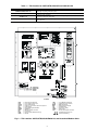
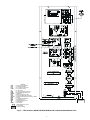
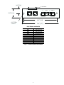
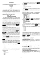
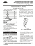
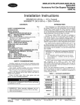
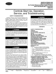
1
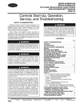
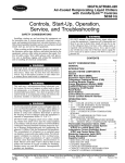
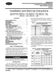
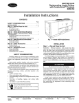
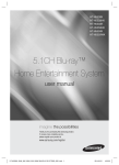
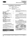
30GTN015-035
30GTN,GTR,GUN,GUR040-420
30HK040-060,30HL050-060,30HW018-040
ComfortLink™ Navigator Accessory Display Module
50/60 Hz
Installation Instructions
Part Number 30GT-911---062
CONTENTS
Com
SAFETY CONSIDERATIONS . . . . . . . . . . . . . . . . . . . . . . 1
GENERAL . . . . . . . . . . . . . . . . . . . . . . . . . . . . . . . . . . . . . . . . 1
INSTALLATION . . . . . . . . . . . . . . . . . . . . . . . . . . . . . . . . . 1-5
OPERATION . . . . . . . . . . . . . . . . . . . . . . . . . . . . . . . . . . . . .6,7
CLEANING, SERVICE AND MAINTENANCE. . . . . . . 7
NA
T IM E
EWT
LW T
SETP
MO
Run
fort
VIG
Lin
ATO
R™
k
12.
54. 58
44. 6°F
4 4 . 01 ° F
°F
DE
Al ar
Statu
s
Servi
ce Te
Temp
m St
atu
s
st
eratur
es
Pres
sures
SAFETY CONSIDERATIONS
Setpo
ints
Inputs
Outpu
ts
Confi
gurat
Time
Installation of this accessory can be hazardous due to system pressures, electrical components, and equipment location
(such as a roof or elevated structure).
Only trained, qualified installers and service technicians
should install, start up, and service this equipment.
When installing this accessory, observe precautions in the
literature, labels attached to the equipment, and any other
safety precautions that apply.
• Follow all safety codes.
• Wear safety glasses and work gloves.
• Use care in handling and installing this accessory.
ELECTRIC SHOCK HAZARD.
To avoid the possibility of electrical shock,
open and tag all disconnects before installing this equipment.
GENERAL
Check Package Contents — Check package for
missing parts or shipping damage. If damage is found, or any
part is missing, file a claim with the shipper immediately. The
package contains these instructions, clamp and screw, and the
Navigator module.
The Navigator is a portable display module that conforms to
NEMA 4 specifications for outdoor use in temperatures ranging from –22 F (–30 C) to 158 F (70 C). The Navigator can be
used to configure and perform service diagnostics on machines
equipped with Carrier ComfortLink controls.
The Navigator keypad (see Fig. 1) contains eleven menu
LED's and one Alarm Status LED, all of which are red. The
Navigator is capable of displaying four 24-character lines of information on a back-lit liquid crystal display. The Navigator
has four functional keys which are the up arrow (
), down
arrow (
), ENTER and ESCAPE keys.
ion
Cloc
k
Opera
Alarm
ting
s
ENT
Mode
s
ESC
ER
Fig. 1 — Navigator in Display Mode
INSTALLATION
1. The Navigator display module is intended to be a mobile
device, so there are no holes in the device for permanent
mounting. The module has a magnetic mount that is
strong enough to hold the device in place on any clean,
dry metal surface.
2. The Navigator module is powered through the
ComfortLink Main Base Board (MBB). The Navigator
has a modular telephone style (RJ14) connector and
should be connected to terminal block TB3 in the control
box. This device is intended for use on the LEN (Local
Equipment Network) communications bus only. Do NOT
connect the Navigator to the CCN (Carrier Comfort Network) connector. You may damage the device. Terminal
block TB3 locations are listed in Table 1 on page 2.
3. Figures 2-4 show TB3 locations in the units. Note that the
LEN connector is clearly marked and is on the right side
of the terminal block. If the Navigator is intended to remain with the chiller, secure the cable near TB3 to prevent accidental damage to the RJ14 connector or the TB3
LEN connector. A clamp and screw are provided in the
package for this purpose. An 1/8-in. hole should be drilled
to use the clamp and screw.
4. Figure 5 shows Communication board details and
dimensions.
Manufacturer reserves the right to discontinue, or change at any time, specifications or designs without notice and without incurring obligations.
PC 903
Catalog No. 533-00001
Printed in U.S.A.
Form 30G,H-9SI
Pg 1
6-00
Replaces: New
Book 2
Tab 5c
Table 1 — TB3 Location for 30GTN,GTR,GUN,GUR and 30HK,HL,HW
UNIT MODEL
30GTN,GTR,GUN,GUR040-110*
30GTN,GTR,GUN,GUR130-210*
30GTN015-035
30HK,HL040-060 and 30HW018-040
DESCRIPTION OF TB3 LOCATION
Open control door (left side) at end of unit. TB3 is located in the bottom left corner of the control
box through an opening in the inner panel.
Open the control door on the compressor side of the unit. TB3 is located on a bracket attached to
the left side of the control box.
Open control door at end of unit. TB3 is located in the upper right corner of the control box
through an opening in the inner panel.
TB3 can be accessed without opening the control box door. It is located at the upper right corner
of the control box.
*And associated modular sizes.
(
)
LEGEND
CCN
CHT
CLHR
CPCS
CR
EMM
EQUIP
EXV
FB
FIOP
GND
—
—
—
—
—
—
—
—
—
—
—
Carrier Comfort Network
Cooler Heater Thermostat
Cooler Heater Relay
Compressor Protection and Control System
Control Relay
Energy Management Module
Equipment
Electronic Expansion Valve
Fuse Block
Factory-Installed Option Package
Ground
LEN
LLSV
MBB
NEC
TB
TDR
TRAN
TXV
—
—
—
—
—
—
—
—
Local Equipment Network
Liquid Line Solenoid Valve
Main Base Board
National Electrical Code
Terminal Block
Time-Delay Relay
Transformer
Thermostatic Expansion Valve
Terminal Block Connection
Field Control Wiring
Fig. 2 — TB3 Location, 30GTN,GTR,GUN,GUR040-110, and Associated Modular Units
2
(
CCN
CGF
CHT
CLHR
CR
CXB
EMM
EQUIP
EXV
FIOP
GFI-CO
GND
LEN
MBB
NEC
TB
TRAN
—
—
—
—
—
—
—
—
—
—
—
—
—
—
—
—
—
)
LEGEND
Carrier Comfort Network
Circuit Ground Fault
Cooler Heater Thermostat
Cooler Heater Relay
Control Relay
Compressor Expansion Board
Energy Management Module
Equipment
Electronic Expansion Valve
Factory-Installed Option Package
Ground Fault Interrupter Convenience Outlet
Ground
Local Equipment Network
Main Base Board
National Electrical Code
Terminal Block
Transformer
Terminal Block Connection
Factory Wiring
Field Power Wiring
NEC FUSED
DISCONNECT
Fig. 3 — TB3 Location, 30GTN,GTR,GUN,GUR130-210, and Associated Modular Units
3
FIELD POWER SUPPLY
SEE OTHER
LABELS
CCN
CONNECTIONS
LEN
CONNECTION
(NAVIGATOR)
A
C
CB
CR
EMM
GCS
GND
MBB
POT
SW
TB
TRAN
—
—
—
—
—
—
—
—
—
—
—
—
LEGEND
Alarm
Contactor, Compressor
Circuit Breaker
Control Relay
Energy Management Module
Ground Current Sensing
Ground
Main Base Board
Potentiometer
Switch
Terminal Block
Transformer
Terminal Block
Field Power Wiring
Fig. 4 — TB3 Location, 30HK,HL040-060; 30HW018-040, 30GTN015-035
4
0.63” [16]
PLUG TERMINAL
1
8
(+)
(COM)
(-)
1.25” [31.8]
LEN
CCN
CCN
4.50” [114]
0.19” DIA,
2 PLCS.
5.00” [127]
ELECTRICAL SCHEMATIC
PLUG TERMINAL
PIN 1
PIN 2
PIN 3
PIN 4
PIN 4
PIN 5
PIN 5
PIN 6
PIN 6
PIN 7
PIN 7
PIN 8
PIN 8
TRACE TO
LEN PLUG, PIN 2
LEN PLUG, PIN 3
LEN PLUG, PIN 5
LEN PLUG, PIN 1
CCN PLUG, PIN 1
LEN PLUG, PIN 6
CCN PLUG, PIN 6
CCN PLUG, PIN 5
CCN SCREW ‘-’
CCN PLUG, PIN 3’
CCN SCREW ‘COM’
CCN PLUG, PIN 2
CCN SCREW ‘+’
Fig. 5 — Communication Board Detail
5
SHIELD
OPERATION
To view an expansion of the sub-mode, press the ENTER
and ESCAPE keys simultaneously and the Navigator will
display:
>SLCT
SET POINT AND RAMP
LOAD
To use the Navigator, plug the RJ14 connector into the LEN
port at TB3. On power up, the Navigator displays:
ComfortLink
Navigator
By
Carrier
The Navigator will remain in the expanded display mode
until the ESCAPE key is pressed. Use the arrow keys to view
expansions for any of the other sub-modes within the Configuration mode.
Once a sub-mode is selected, the first four items in that submode will be displayed. For example, in the Temperatures
mode, under the sub-mode UNIT, the Navigator will display:
>CEWT 54.2 °F
CLWT 44.1
°F
OAT
85.6 °F
SPT
70.3
°F
The Navigator will upload the appropriate display tables
from the Main Base Board (MBB) that it is connected to. A
‘Communication failure’ message will be displayed if any
errors are encountered. Check the wiring at the connector or the
MBB-J5 plug if necessary. After successful upload of information, the Navigator begins its default display. All items in the
Run Status menu are displayed one at a time in this mode. An
example of the display in the default mode is:
EWT 54.2 °F
ENTERING FLUID TEMP
The different levels of modes can be accessed with the
Navigator. See the base unit controls and troubleshooting guide
for more information.
Pressing any key while in the default display mode will
cause the Navigator to enter its manual mode. In this mode, all
sub-modes and items within the eleven top level configuration
modes, denoted on the display screen, can be accessed. The
Navigator automatically returns to the default display mode after 60 minutes of no keypad activity. Pressing the ENTER and
ESCAPE keys simultaneously while the unit displays “Select
a menu item” will also log the device out and return it to its default display mode.
Press the ENTER and ESCAPE keys simultaneously
while the pointer is at ‘CEWT’ and the Navigator will display:
CEWT 54.2 °F
COOLER ENTERING
FLUID
As in the sub-mode structure level, the Navigator will remain in the expanded display mode until the ESCAPE key is
pressed.
Under the Alarms mode, the Navigator displays current
alarms (CRNT sub-mode) in the following manner:
>1 A200
2 A152
3 T051
4 T055
Navigating through Menu Structures — The arrow keys are used to scroll up and down to select sub-modes
within a mode or items within a sub-mode. See the base unit
troubleshooting guide for menu structure. The ENTER key is
used to select a menu item or to accept data entry. The
ESCAPE key is used to exit to the next highest mode or to
cancel data entry. The sub-mode and item displays will wrap
around with the last and first items separated by a line of dashes
on the display. The ‘>’ symbol is the pointer and is located at
the left side of the display.
Press the ESCAPE key to display “Select a menu item” on
the screen. This is the top level and the arrow keys are used to
move the red LED to the one of the 11 desired modes. Press
ENTER to display the sub-modes within a top level mode.
Use the arrow keys to move the pointer (‘>’) to the desired
sub-mode. Up to four sub-modes will be displayed on the
Navigator at one time. Continue pressing the arrow keys as
needed to find the desired sub-mode. As an example, the Configuration mode contains six sub-modes. When the ENTER
key is pushed at the top level, the Navigator displays:
>DISP
UNIT
OPT1
OPT2
If there are no current alarms, “No Active Alarms” will be
displayed. Similarly in the HIST sub-mode, if the alarm history
is empty, “Alarm History Clear” will be displayed. Press the
down arrow until the pointer reaches T051. Pressing the
ENTER and ESCAPE keys with the pointer at T051 as
above will display:
>T051
CIRCUIT A
COMPRESSOR 1
FAILURE
Password Protection — If an area is entered that is
password protected or an item is selected for change that is
password protected, the Navigator will display:
Enter Password
1111
The first digit of the password will be flashing. Hold either
of the arrow keys down to change the value of the first digit (if
necessary) and press ENTER to accept. Repeat the process for
the remaining three digits.
The message “Invalid Password” is displayed if the password is not correct. The password can not be disabled from the
Navigator, nor can it be changed.
To access the sub-mode to change the Cooling Setpoint
Select item, press the up arrow key to scroll up until the Navigator display reads:
>SLCT
--------------------UNIT
OPT1
Forcing Values and Configuring Items — Certain items are allowed to be forced and other items are
user-configurable. Both of these changes can be made using
the Navigator. See Table 2.
6
Table 2 — User Configurable Items
MODE
SUB-MODE
Run Status
RUN
HOUR
STRT
ITEM
COMMENT
All
Edit when replacing MBB to
keep total machine hours/
starts
—
Service Test
All
All
Temperatures
UNIT
OAT.SPT
—
Setpoints
All
All
—
Configuration
All
All
All items in all sub-modes
can be changed except for
“TYPE” in sub-mode “UNIT”
Time Clock
All
All
—
Alarm History
RCRN
RHIS
—
—
ADJUSTING BRIGHTNESS — Pressing ENTER will
cause the “OFF” to flash. Use the up or down arrow keys to
change “OFF” to “ON”. Pressing ENTER will illuminate all
LEDs and display all pixels in the view screen. Pressing
and
simultaneously allows the user to adjust the display
brightness. The display will read:
Adjust Brightness
---------------+
Use the up or down arrow keys to adjust the brightness.
The screen’s brightness will change with the adjustment. Press
ENTER to accept the change. The Navigator will keep this
setting as along as it is plugged in to the LEN bus.
CLEANING, SERVICE and MAINTENANCE
Only the OAT (Outside Air Temperature) and SPT (Space
Temperature) items can be forced. To force one of these items,
position the pointer at the item. Press the ENTER key and the
current value will flash. Use the arrow keys to adjust the temperature to the desired value. Press the ENTER key when finished and the Navigator will display a lowercase ‘f’ to the right
of the value indicating that it has been forced. To clear a force,
press ENTER so that the value is again flashing. Simultaneously press the up and down arrow keys. The value will stop
flashing, the ‘f’ will be removed and the value will read the
corresponding input channel for its value.
To edit a user-configuration item, operate the chiller in
Service Test mode, enter run hours and compressor starts or reset current alarms or history, use the ENTER key to make the
value flash. Next, use the arrow keys to adjust the item so that
the desired value is displayed and press ENTER .
Cleaning — The Navigator can be cleaned with a mild
detergent. Isopropyl alcohol or a glass cleaner can be used on
all Navigator surfaces.
Connection Cord/Plug Assembly Replacement — If the RJ14 plug is damaged, it can be replaced. If it
is replaced, the wiring to the plug must be as shown below:
PIN
1
2
3
4
5
6
Wire Color
Black
Green
Blue
Yellow
Red
White
TAB
Adjusting the Contrast — The contrast of the display
can be adjusted to suit ambient conditions. To adjust the contrast of the Navigator, press the ESCAPE key until the display reads, “Select a menu item.” Using the arrow keys move
to the Configuration mode. Press ENTER to obtain access to
this mode. The display will read:
>TEST OFF
METR OFF
LANG ENGLISH
PIN
1
2
3
4
5
6
The connection cable can be replaced if damaged. Replacement cables are available from Replacement Components
Division. Remove the Navigator from the LEN connection before proceeding.
1. Remove the 6 screws from the back of the case to gain
access to the internal plug for the device, and keep
them for installation later.
2. The back cover is connected to the touch pad by a ribbon
cable. The ribbon cable is not long enough to allow the
two halves to be completely separated. To be able to access the plug connection, slightly offset the back cover.
Be careful not to damage the ribbon cable.
3. Unplug the damaged cable.
4. Plug in the new cable.
5. Insert the rubber grommet (included with new cable assembly) into the cable entrance hole.
6. Realign the two halves of the Navigator. Be sure that the
grommet is properly seated in the cable entrance hole.
7. Reinstall the 6 screws previously removed.
Pressing ENTER will cause the “OFF” to flash. Use the up
or down arrow to change “OFF” to “ON”. Pressing ENTER
will illuminate all LEDs and display all pixels in the view
screen. Pressing ENTER and ESCAPE simultaneously allows the user to adjust the display contrast. The display will
read:
Adjust Contrast
---+-----------Use the up or down arrows to adjust the contrast. The
screen’s contrast will change with the adjustment. Press
ENTER to accept the change. The Navigator will keep this
setting as along as it is plugged in to the LEN bus.
Adjusting the Backlight and Brightness — The
backlight of the display can be adjusted to suit ambient conditions. The factory default is set to the highest level. To adjust
the backlight of the Navigator, press the ESCAPE key until
the display reads, “Select a menu item.” Using the arrow keys
move to the Configuration mode. Press ENTER to obtain access to this mode. The display will read:
>TEST OFF
METR OFF
LANG ENGLISH
NOTE: Failure to properly seal the Navigator with the screws
and grommet will compromise the watertight integrity of the
device.
7
Copyright 2000 Carrier Corporation
Manufacturer reserves the right to discontinue, or change at any time, specifications or designs without notice and without incurring obligations.
PC 903
Catalog No. 533-00001
Printed in U.S.A.
Form 30G,H-9SI
Pg 8
6-00
Replaces: New
Book 2
Tab 5c