1
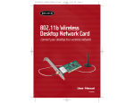
P74056_F5D6001_man(fp).qxd
5/3/2002
5:08 PM
Page 1
P74056_F5D6001_man(fp).qxd
5/3/2002
5:08 PM
Page 2
Wireless Desktop Network F5D6001
Card
P74056_F5D6001_man(fp).qxd
5/3/2002
5:08 PM
Page 1
wireless networking
table of contents
Introduction
Features
•••••••••••••••••••••••••••••••••••••••
2
••••••••••••••••••••••••••••••••••••••••••
2
•••••••••••••••••••••••••••••••••
3
System Requirements
••••••••••••••••••••••••••••••••••
3
Contents of Package
••••••••••••••••••••••••••••••••••
3
Product Specifications
Knowing Your Belkin Wireless Desktop Network Card • • • • • • • • • • • • • • 4
Optional Desktop Antenna
••••••••••••••••••••••••••••••
Installing and Setting Up the Card
•••••••••••••••••••••••••
Step 1—Software and Driver Installation
Step 2—Installing the Card into Your PC
•••••••••••••••••
for Windows 98, Me, 2000, and XP
•••••••••••••••
5
6
6-7
7-8
Step 3—Finishing the Installation • • • • • • • • • • • • • • • • • • • • • • • 9
Uninstalling the Software and Drivers
Using the Card
•••••••••••••••••••••••
•••••••••••••••••••••••••••••••••••
9
10-13
Windows XP • • • • • • • • • • • • • • • • • • • • • • • • • • • • • • • • • • • • 10
Windows 98, Me, 2000 • • • • • • • • • • • • • • • • • • • • • • • • • • • • 13
Link Status Tab • • • • • • • • • • • • • • • • 14-15
Configuration Tab • • • • • • • • • • • • • • 16
Using Profiles
•••••••••••
Network Name Box
Operating Mode
Transmit Rate
Encryption
Site Monitor Tab
17-18
••••
18-19
•••
19-20
•••••••
•••••••••
••••••••••••
Wireless Networking Using 802.11b
21
22-24
•••
25
26
Peer-to-Peer (Ad-Hoc) Network • • • • • • • • • • • • • 26
Infrastructure Network (Access Point)
Roaming
•••••••
•••••••••••••••••••••••••••••••••••••••
Glossary of Wireless Networking Terms
••••••••••••••••••••
27
28-29
30-33
FCC/CE/Warranty Information • • • • • • • • • • • • • • • • • • • • • • • • • • 34-36
1
P74056_F5D6001_man(fp).qxd
5/3/2002
5:08 PM
Page 2
wireless networking
wireless networking
Introduction
Product Specifications
Thank you for purchasing the Belkin Wireless Desktop Network Card (the
Card). This high-speed Card provides you with an innovative wireless
networking solution that is easy to set up and use. The Card transmits at
a rate of 11, 5.5, 2 or 1Mbps to let you share files and printers on the
network—without the hassle and inconvenience of connecting wires!
Operating in the ISM band using Direct Sequence Spread Spectrum (DSSS)
transmission, the Card implements the IEEE 802.11b standard and supports
Windows© 98, 2000, Me, or XP operating systems.
Host Interface:
32-bit, PCI 2.x-compliant
Power Consumption:
300mA (Max.)
OS Support:
Windows 98, 2000, Me, or XP
Certification:
FCC Class B, CE Mark, C-Tick
Operating Temperature:
0˚ C to 55˚ C
Storage Temperature:
–25˚ C to 70˚ C
Typical Operating Range:
Indoor: 160' (50m) @11Mbps, 260'
(80m) @5.5Mbps or lower
Features
Outdoor: 490' (150m) @11Mbps, 980'
(300m) @ 5.5Mbps or lower
The Card complies with the IEEE 802.11b standard in order to communicate
with other 802.11b-compliant wireless devices.
• 2.4GHz ISM (Industrial, Science, and Medial) band operation
System Requirements
• Includes an easy-to-use profile manager for storing multiple wireless
network settings for work, school, home, etc.
• PC with available PCI expansion slot
• Wireless interface compliance with the IEEE 802.11b standard
• PC running Windows 95, 98 SE, 2000, NT®, Me, or XP
• PCI interface, complies with PCI specification 2.1
• CD-ROM drive (for loading software)
• 64- or 128-bit Wired Equivalent Privacy (WEP) wireless encryption, for
the same security and privacy levels available in a wired LAN
Contents of Package
• Wireless access to networked resources
• Belkin Wireless Desktop Network Card
• Support for both Infrastructure and Ad-Hoc (Peer-to-Peer)
networking modes
• External Antenna
• Data rate of up to 11Mbps
Supports 11, 5.5, 2 or 1Mbps rates (Auto-Rollback)
• Quick Installation Guide
• Software CD
• User Manual
• Easy to install and use
• External detachable antenna; optional desktop antenna
• LED link indicator
2
3
P74056_F5D6001_man(fp).qxd
5/3/2002
5:08 PM
Page 4
wireless networking
Knowing Your Belkin Wireless Desktop Network Card
Warning! Your Card is sensitive to static electricity. Handle the Card by
the edges and avoid touching the PCI edge connector or any of the
components on the green printed circuit board.
Antenna
Power
PCI Edge
Connector
wireless networking
Optional Desktop Antenna—F5D6900 (not included)
Belkin provides an optional Desktop Antenna to extend the antenna to
your desktop. While the antenna that ships with the Card is optimal for
most uses, there are some instances where moving the antenna above the
desktop is necessary to ensure good signal quality and strength. Use the
optional Desktop Antenna if, for instance, your computer is placed under
or next to a desk that is made of metal, or is under a desk near metal
drawers. Metal structures like filing cabinets and drawers can effectively
block the wireless signal. The optional Desktop Antenna is available from
www.belkin.com. Part number: F5D6900
F5D6900 Optional
Desktop Antenna
Link
Power LED
Solid: Power is on
Off: Power is off
Link LED
Solid: Linked to the wireless network
Blinking: Scanning for a wireless network
4
SMA Reverse
Male Connector
5
P74056_F5D6001_man(fp).qxd
5/3/2002
5:09 PM
Page 6
wireless networking
wireless networking
Installing and Setting Up the Card
Installing your Card is done in three easy steps.
1. Install the software FIRST. If you install the Card inside of your PC
before you install the software, it will not work until you install
the software.
2. Install the Card inside of your PC.
3. Turn on your PC and let Windows operating system (OS) finish installing
the Card.
NOTE: INSTALL THE SOFTWARE FIRST BEFORE YOU INSTALL THE CARD
INTO YOUR PC
Step 1: Software and Driver Installation
1. Insert the CD into your CD-ROM drive.
2. The “Wireless Desktop Network Card Setup Utility” screen should
automatically appear. If it does not appear within 15–20 seconds,
then select your CD-ROM drive and double-click on the folder named
“Files”. Next double-click on the icon named “LAN_UTILITY.exe”.
3. In the utility screen, drag your mouse over the “Install” button, then
select “Click here” to start the software installation program.
4. The Wireless Desktop Network Card installer will automatically copy all
of the needed files to your computer. When prompted, click “Finish” to
complete the copy process.
5. Remove the CD from the CD-ROM drive and shut down your computer.
Note: Be sure to properly exit your Windows OS by clicking “Start” >
“Shut Down”.
6. Follow the directions in Step 2 to install the Card inside of
your computer.
Step 2: Installing the Card into Your PC for Windows 98,
Me, 2000, and XP
1. POWER OFF THE COMPUTER AND DISCONNECT THE POWER CORD.
2. Remove the screws that secure the computer cover and remove
the cover.
3. Touch any metal part of the case. This will discharge any static
electricity that could damage your product or your computer.
4. Locate an empty PCI expansion slot.
5. Confirm that the Card will fit into the slot you have chosen. Keep in
mind that the included antenna needs to be oriented with the top
pointing up. If there are cables and other connectors in the way, try
to pick the PCI slot that has the fewest obstructions to the correct
positioning of the antenna.
6. Remove the port cover from the back of the PC that corresponds to the
PCI slot you selected. If there is a screw, place it in a safe place as you
will be using it to attach the Card to the computer chassis later.
7. Push the Card firmly into the PCI slot that you have chosen. Apply
pressure as needed until the connector is fully seated.
8. Now secure the Card with the screw that you previously placed in a
safe place.
6
7
P74056_F5D6001_man(fp).qxd
5/3/2002
5:09 PM
Page 8
wireless networking
9. Carefully screw the antenna onto the threaded connector on the Card.
Turn the antenna until it is vertical and pointing up.
wireless networking
Step 3: Finishing the Installation
1. Turn your computer on.
2. Depending on your operating system, Windows OS may detect the Card
and launch the “Found New Hardware” wizard. Click “Next”.
3. Your Windows OS may ask you where the drivers are located. Make no
changes and click “Next”.
4. If you are using Windows 2000 or XP, you will get a message telling you
that the drivers are not “signed” by Microsoft. This does not mean there
is a problem. Click “Continue”.
5. Your Windows OS will find the correct driver files and complete the
installation. Windows OS may tell you that the hardware is installed.
Click “Finish” if asked to.
6. Windows OS may ask you to restart the computer. If it does, click “Yes”
or “Restart”.
7. When the computer restarts, an icon will appear in the bottom righthand corner of your screen. See below:
Windows 98, Me, 2000
Windows XP
8. Installation is complete. Go to the next section called “Using the Card”.
Uninstalling the Software and Drivers
10. Replace the computer’s cover.
11. Now that the Card is installed, you can replace the cover to your
computer, reconnect all of the cables, and turn it back on. Proceed
to Step 3.
8
If you need to remove the software and drivers for any reason, you can
accomplish this easily in one of two ways. You can insert the software CD
and click on the “Uninstall” option in the menu, or you can go to the
Windows Control Panel and select the “Add/Remove Programs” option. The
Belkin Wizard will walk you through the removal process.
9
P74056_F5D6001_man(fp).qxd
5/3/2002
5:09 PM
Page 10
wireless networking
Using the Card
wireless networking
3. In the next window, click on “Network Connections”.
Windows XP
If you are using Windows XP, there are two methods by which you can
control your Card. Windows XP has built-in management for wireless
networking products or you can use the management software
(recommended). For information on how to use Windows XP to control
your Card, consult the Windows XP “Help” files or the Microsoft website.
We recommend that you use the software that Belkin provides to manage
your Card. You will find the management software easy to use with more
functionality. To use the Belkin software, follow these steps to configure
Windows XP to let you use the Belkin software.
1. Open the Control Panel by clicking “Start”, then “Control Panel”.
2. In the Control Panel, click on “Network and Internet Connections”.
4. The “Network Connections” window will now be open. Double-click on
the icon labeled “Wireless Network Connection (Belkin 11Mbps Wireless
Desktop Network Card)”.
10
11
P74056_F5D6001_man(fp).qxd
5/3/2002
5:09 PM
Page 12
wireless networking
5. The “Wireless Network Connection Properties” window will appear. Click
on the tab labeled “Wireless Networks”.
wireless networking
Windows 98, Me, 2000
The Card is equipped with a management utility that allows you to change
the settings of the wireless Card, see the wireless signal strength, turn the
Card’s radio on or off, and much more. The Card also puts an indicator icon
in the bottom right-hand corner of your computer (the system tray) that
gives you a quick look at your wireless signal quality.
Green
or
: Excellent signal quality
Yellow
or
: Fair signal quality
Red
or
: Poor to no signal quality
To Open the Wireless Manager Utility Screen
6. Remove the check mark next to “Use Windows to configure my wireless
network settings”.
To access the management utility, double-click on the
icon (Windows
98, Me, 2000) or
(Windows XP) in the bottom right-hand corner of
your computer screen. The “Belkin Wireless LAN Utility” window will
open. You will see the “Link Status” tab. There are four tabs that
perform different functions.
7. Click “OK”.
12
8. Windows XP is now configured to let the Belkin software control the
Card. Follow the directions in the next section titled “Windows 98, Me,
2000” to operate the Card.
13
P74056_F5D6001_man(fp).qxd
5/3/2002
5:09 PM
Page 14
wireless networking
Link Status Tab
Channel Display
This displays the current channel that the wireless network is operating
on. In a wireless network using a wireless router or an access point, the
wireless router or access point determines the operating channel. In a
computer-to-computer network, the channel is determined by you. For
more information, see the “Operating Mode” section.
Tx Rate Display
This shows the current rate at which the Card will transmit and receive
wireless data. For more information, see the “Transmit Rate” section.
Throughput Display
Transmit: This field shows the wireless transmission throughput in
bytes-per-second.
Receive: This field shows the wireless receipt throughput in
bytes-per-second.
Link Quality/Signal Strength Displays
Link Quality bar: Indicates the quality of the link between the Card and
the wireless network. Signal Strength bar: Indicates the strength of the
signal coming from the wireless network.
State Display
wireless networking
Associated: The Card is connected to a wireless network. The numbers
following the word “Associated” refer to the MAC address of the wireless
access point that the Card is connected to.
Scanning: The Card is searching for an available wireless network and will
automatically scan for one. If the Card continues to scan without joining a
network, this means that there are no available networks in your area, or
there is another problem.
Disable Radio/Enable Radio Button
It is possible to completely turn off the Card’s wireless transmitter (radio)
by pressing the “Disable Radio” button. After pressing the button, it will
change to read “Enable Radio”. To enable the radio again, click the “Enable
Radio” button.
Power Saving
The power saving mode will turn the card off when it is not in use. We recommend that you leave this option disabled. When enabled, there will be a
short delay to turn the Card on before it can transmit and receive data.
This delay can make your Internet connection appear to be slow.
Reconnect
If your Card loses the connection to the wireless network for any reason,
simply click on the “Reconnect” button to scan for the wireless network
and reconnect to it.
This field shows you if the Card is connected to a wireless network or if it
is searching for a wireless network. There are two states:
14
15
P74056_F5D6001_man(fp).qxd
5/3/2002
5:09 PM
Page 16
wireless networking
wireless networking
Configuration Tab
Using Profiles
The “Configuration” tab allows you to set different profiles, network
names, network types, and adjust the Transmit Rate.
The first thing you will notice is the “Profile Name” bar. Using profiles
allows you to save configurations for different wireless networks. For
instance, if you use your Card at your place of work and also at your
home, your wireless network settings may be different for each location.
Profiles let you store settings for each location and name them for easy
identification. The “default” profile will contain the initial configuration
setting when you install the Card.
In Ad-Hoc mode, each wireless device will use the same SSID to create a
small wireless network. For instance, if you want to connect a PDA to a
PC, then both must have the same SSID such as “WLAN”. In addition, the
wireless channel must also be the same. See “Ad-Hoc Channel”.
To Create a New Profile
1. Click the “New” button. The current entry will be highlighted. Type a
new name such as “Work”.
2. Click the “Apply” button to save the profile name.
3. Any changes you make to the wireless settings will now apply to
this profile.
16
17
P74056_F5D6001_man(fp).qxd
5/3/2002
5:09 PM
Page 18
wireless networking
To Select a Profile
1. Click the down-facing arrow next to the “Profile Name” bar. A drop-down
list of profiles will appear (see below). Note: If you have not saved any
profiles, only the “Default” profile will appear as a selection.
wireless networking
name, the Card will search for the closest available wireless network
and join it. If you know the specific network name, you can type it
into the “Network Name” field to join that network.
To Enter a New Network Name
1. Click inside of the “Network Name” box.
2. Enter the name of the wireless network you wish to join.
Note: Type “ANY” to join the closest wireless network.
3. Click the “Apply” button to save the changes.
2. Select the profile you want to use by clicking on it.
3. Click “Apply” to save the change.
The settings for the profile you selected will now be in use.
To Delete a Profile
1. Select the profile you wish to delete.
2. Click the “Delete” button.
3. Click “Apply”.
The profile is now deleted.
To Restore the Default (Factory) Settings
Click the “Defaults” button to restore the factory settings.
Network Name Box
18
The “Network Name” display lets you specify the name of the wireless
network that you want to join. The default factory setting for the
“Network Name” is “ANY”. When “ANY” is entered into the network
Operating Mode
There are two modes of wireless networking that exist. The first and most
common mode is called “Access Point” or “Infrastructure”. The second
mode is called “Peer-to-Peer” or “Ad-Hoc”.
Access Point Network Mode
Use this mode when you are connecting to a wireless network that uses an
access point or wireless router.
Peer-to-Peer Mode
Use this mode when connecting directly to other wireless computers in a
network that uses no access point or wireless router.
19
P74056_F5D6001_man(fp).qxd
5/3/2002
5:09 PM
Page 20
wireless networking
To Join an Access Point Wireless Network
If you want to join a wireless network that uses an access point or a
wireless router:
2. Type in the name of the network into the “Network Name” box. Note:
“ANY” does not work in Peer-to-Peer mode. The Network Name can
be anything you want it to be (for instance, “Home”).
1. Select “Access Point” in the “Operating Mode” box by clicking the
down-facing arrow and highlighting your selection.
3. Select an operating channel by clicking on the up/down arrows next to
“Peer-to-Peer Channel”. Note: All computers must be on the same channel.
2. Type in the name of the network into the “Network Name” box or
type “ANY” to join the closest wireless network. This is the default
factory setting.
4. Click “Apply” to save the changes.
3. Click “Apply” to save the changes.
The 802.11b wireless Ethernet standard was engineered so it can operate
at different data rates depending on the environment that it is working in.
The maximum data rate is 11Mbps (11 megabits-per-second or 11 million
bits-per-second). Under the best of circumstances, the data will be
transferred at the highest rate. When excessive noise or other radio
signals enter the air, or the wireless device is far enough away from the
access point that the signal is weak, the chances that wireless data can
be corrupted with data errors grows. Data errors result in a slow transfer
of data (or connection) because the data has to be resent over and over
until there are no errors. To combat this, in “Fully Automatic” mode, the
data rate will automatically be rolled back to a slower rate to eliminate
errors by giving the signal more time to reach its intended destination.
The result is the fastest transmission possible. There are four possible
data rates: 11Mbps, 5.5Mbps, 2Mbps, and 1Mbps. We recommend that you
leave the Transmit Rate at “Fully Automatic” and let the Card do the job
of transmitting the data at the fastest possible rate. If you set the
Transmit Rate at a fixed setting, this will force data to be sent at that
rate, but errors may occur causing the data to be resent. This could
actually make the connection SLOWER.
To Join or Create a Peer-to-Peer Wireless Network
If you want to join or create a computer-to-computer network, the
“Network Name” and the “Peer-to-Peer Channel” boxes for each computer
must be the same. Each computer must be configured to Peer-to-Peer
operating mode.
1. On each computer, select “Peer-to-Peer” in the “Operating Mode” box by
clicking the down-facing arrow and highlighting your selection.
20
wireless networking
Transmit Rate
21
P74056_F5D6001_man(fp).qxd
5/3/2002
5:09 PM
Page 22
wireless networking
Encryption
For security, the 802.11b standard incorporates a method of “scrambling”
the data being sent over the air. This is called WEP (Wired Equivalent
Privacy). There are two different levels of WEP: 64-bit encryption and
128-bit encryption. 64-bit encryption is powerful and secure; 128-bit
encryption is very powerful and very secure. The reason that two levels,
or rates, of encryption exist is because encryption will slow the data
speed down. The higher the rate of encryption, the slower the data will
be transmitted. 64-bit encryption will reduce data rates nearly 30–40
percent where 128-bit encryption will reduce data rates around 50–60
percent. The trade-off is higher security for slower performance. Keep in
mind, however, only large file transfers or continuous streaming data are
most affected by this. Normal browsing of the Internet, downloading files,
and sending and retrieving e-mails is not affected.
wireless networking
To Create an Encryption Key Using a Passphrase—EASY FOR
NOVICE USERS
1. Click the “Encryption” tab.
2. Select the rate of encryption you need to use from the drop-down menu.
How to Use Encryption
Encryption is fairly easy to understand. Encryption uses what are called
“keys” to encode and decode, or “scramble” and “unscramble”, data.
Keys can be made by entering a passphrase (password) or can be entered
manually into the system using an alphanumeric series or a series of
two-digit numbers (called “hexadecimal”). In Infrastructure mode, where
an access point or wireless router is being used, the access point or
wireless router is programmed with an encryption key. For a wireless
device to join the wireless network, the same encryption key must be
programmed into the device. Your Card can be programmed with a key
in either the passphrase (easy) manner or with alphanumeric or
hexadecimal (advanced) entries.
3. Select “Create Keys with Passphrase”.
4. Type the network passphrase you need to use into the “Passphrase” box
(for instance, “Passphrase”).
5. Click “Apply” to save the passphrase.
22
23
P74056_F5D6001_man(fp).qxd
5/3/2002
5:09 PM
Page 24
wireless networking
To Create an Encryption Key Manually—FOR ADVANCED USERS ONLY
1. Click the “Encryption” tab.
2. Select the rate of encryption you need to use from the drop-down menu.
3. Select “Create Keys Manually”.
4. There are two methods of entering the key, alphanumeric or hexadecimal.
If you want to enter an alphanumeric key, select “Alphanumeric:”; select
“Hexadecimal:” to enter a hexadecimal key.
wireless networking
Site Monitor Tab
You can use the Site Monitor to view all available wireless networks within
range of your computer. When you click on the “Site Monitor” tab, you will
see a window showing you basic information about the wireless networks
in your area.
Network Name: displays the name of the wireless network.
Signal: indicates the strength of the signal expressed in dBm.
5. Depending on the rate of encryption you are using, follow the
steps below:
a. 64-bit: If you selected 64-bit encryption, then enter a 5-character
alphanumeric key or a 10-digit hexadecimal key into “Key 1”.
b. 128-bit: If you selected 128-bit encryption, then enter a 13-character
alphanumeric key or a 26-digit hexadecimal key into “Key 1”.
Link Quality: displays the link quality (Excellent, Fair, Poor, Not
Connected).
Note: In many cases, this key should be provided to you by the
network administrator.
Clicking on the “Scan” button will rescan the area for wireless networks.
6. Repeat these steps for keys 2–4 if needed.
Channel: displays the operating channel of the wireless network.
Network Address: displays the MAC address of the wireless network’s
access point.
To join a wireless network that you see in the Site Monitor, double-click
on the name of the network that you want to join.
7. Click “Apply” to save the key(s).
24
25
P74056_F5D6001_man(fp).qxd
5/3/2002
5:09 PM
Page 26
wireless networking
Wireless Networking Using 802.11b
Infrastructure Network (Access Point)
To form a wireless network, two basic components are used. The first is a
wireless adapter for a PC. This can be either a USB wireless adapter or a
PCMCIA adapter. The adapter gives the PC wireless Ethernet capabilities.
The second is a wireless access point, which can connect to a wired LAN
and allow the wireless PCs to be able to access the wired LAN. A wireless
access point can be a stand-alone component or it can be embedded into
a cable/DSL router, thus forming a wireless gateway router. The use of
each of these types of products is outlined later in this article.
The use of a wireless access point to connect a wireless LAN to a wired
LAN is called Infrastructure mode. A wireless access point serves as a
bridge between the wired and wireless network. Connecting the access
point to any port on the wired network will give wireless access to all
wireless-equipped computers within its coverage area. An access point
is configured with a “Service Set Identifier (SSID)”, a “name” given to
the wireless network and used by the wireless-equipped computers to
access the wireless network. Access points can also be configured to use
encryption or they can grant access to computers with specific MAC
addresses. They effectively double the distance that computers in the
wireless LAN can be located from one another. This is because the unit
serves as a central point for routing of all the wireless network traffic
between the wireless-equipped computers. Wireless-equipped computers
networked together in Infrastructure mode form a group called a “Basic
Service Set (BSS)”. Up to 64 individual computers can exist at a single
time in a BSS. This is due to the ability of the wireless access point to
handle no more than 64 clients. The diagram below illustrates how the
wireless access point works to increase the covered area range of your
wireless network.
Wireless networking is very similar to wired networking, except for a
few basic concepts that one must grasp. There are two different ways
to network computers using 802.11b. The first, and least used method is
the “Ad-Hoc” method, also known as “Peer-to-Peer”. The more commonly
used method is called “Infrastructure” mode.
Peer-to-Peer (Ad-Hoc) Network
Ad-Hoc, or Peer-to-Peer, refers to a wireless configuration in which each
computer communicates directly with another. An Ad-Hoc wireless network
(LAN) consists of a group of computers, each equipped with a wireless
adapter, connected directly via radio signals to form an independent
wireless LAN. Computers in a specific Ad-Hoc wireless LAN must be
configured to the same radio channel and network name to communicate
with one another. More than one Ad-Hoc network can exist in the same
space if it is configured to operate on a different channel. There are a
varying number of channels depending on which part of the world you are
operating in. The US has 11 channels, Europe has 13 channels, and Japan
has 14 channels. The following diagram shows a typical Ad-Hoc wireless
LAN configuration.
Notebook with Wireless
Notebook Network Card
26
wireless networking
Notebook with Wireless
Notebook Network Card
PC with Wireless Desktop
PCI Network Adapter
Notebook with Wireless
Notebook Network Card
WAP
Basic Service
Set (BSS)
Notebook with Wireless
Notebook Network Card
PC with Wireless Desktop
PCI Network Adapter
27
P74056_F5D6001_man(fp).qxd
5/3/2002
5:09 PM
Page 28
wireless networking
wireless networking
The diagram below illustrates how a wireless access point acts as a bridge
between the wireless BSS and the wired network.
Desktop PC
Desktop PC
Desktop PC
Wireless
Access Point
Switch
Desktop PC
Switch
BSS2
Wireless
Access Point
Basic Service
Set (BSS)
ESS
Wireless
Access Point
BSS1
Roaming
More than one wireless access point can be used to increase the wireless
coverage in a wireless LAN. The diagram below shows two wireless access
points configured to extend coverage beyond that of a single unit. The
overlapping area of each BSS is called an “Extended Service Set (ESS)”.
When a wireless computer enters the ESS, the computer evaluates the
signal strength and link quality, then chooses the wireless access point
with the best-quality signal and link. This activity is known as “roaming”.
To configure your wireless access points to allow roaming inside of the
wireless network, each unit will be assigned the same Service Set Identifier
(SSID). Strategically placing multiple units around an office or inside of
the home can extend the wireless coverage to the entire premise. The
illustration below shows two Basic Service Sets overlapping to form an
Extended Service Set.
28
29
P74056_F5D6001_man(fp).qxd
5/3/2002
5:09 PM
Page 30
wireless
Glossary of Wirelessnetworking
Networking Terms
Access Point: An internetworking device that seamlessly connects wired
and wireless networks.
wireless
Glossary ofnetworking
Wireless Networking Terms
Roaming: A wireless LAN mobile user moves around an ESS and maintains
a continuous connection to the Infrastructure network.
Ad-Hoc: A group of computers, each with LAN adapters, connected as an
independent wireless LAN.
Desktop PC
Ad-Hoc Mode
Notebook with Wireless
Notebook Network Card
Infrastructure Mode,
BSS, and ESS
Switch
Desktop PC
Wireless
Access Point
BSS2
Notebook with Wireless
Notebook Network Card
PC with Wireless Desktop
PCI Network Adapter
ESS
Wireless
Access Point
BSS1
Backbone: The core infrastructure of a network. The portion of the
network that transports information from one central location to
another, where it is unloaded onto a local system.
Base Station: In mobile telecommunications, a base station is the central
radio transmitter/receiver that maintains communications with the mobile
radio/telephone sets within its range. In cellular and personal communications
applications, each cell or micro-cell has its own base station; each base
station in turn is interconnected with other cells or bases.
BSS: BSS stands for Basic Service Set. It is comprised of an access point
and all the LAN PCs that are associated with it.
ESS: ESS (ESS-ID, SSID) stands for Extended Service Set. More than one
BSS is configured to become an Extended Service Set. LAN mobile users
can roam between different BSSes in an ESS (ESS-ID, SSID).
RTS Threshold: Transmitters contending for the medium may not be
aware of each other. The RTS/CTS mechanism can solve this “hidden
node problem”. If the packet size is smaller than the preset RTS
Threshold size, the RTS/CTS mechanism will NOT be enabled.
WEP: Wired Equivalent Privacy is based on the use of 64-bit or 128-bit
keys and the popular RC4 encryption algorithm. Wireless devices without
a valid WEP key will be excluded from network traffic.
Ethernet: A popular local area data communications network, which
accepts transmission from computers and terminals. Ethernet operates
on a 10 or 100Mbps base band transmission rate, using an unshielded,
twisted-pair cable.
Infrastructure: An integrated wireless and wired LAN is called an
Infrastructure configuration.
30
31
P74056_F5D6001_man(fp).qxd
5/3/2002
5:09 PM
Page 32
wireless
Glossary of Wirelessnetworking
Networking Terms
DHCP: Dynamic Host Configuration Protocol. This protocol automatically
configures the TCP/IP settings of every computer on your home network.
DNS Server Address: DNS stands for Domain Name System, which allows
Internet host computers to have a domain name (such as belkin.com) and
one or more IP addresses (such as 192.34.45.8). A DNS server keeps a
database of host computers and their respective domain names and IP
addresses, so that when a domain name is requested (as in typing
“belkin.com” into your Internet browser), the user is sent to the proper
IP address. The DNS server address used by the computers on your home
network is the location of the DNS server your ISP has assigned.
DSL Modem: DSL stands for Digital Subscriber Line. A DSL modem uses
your existing phone lines to transmit data at high speeds.
Ethernet: A standard for computer networks. Ethernet networks are
connected by special cables and switches, and move data around at up
to 100 million bits-per-second [? or, megabits-per-second (Mbps)].
IP Address: IP stands for Internet Protocol. An IP address consists of a
series of four numbers, separated by periods, that identifies a single,
unique Internet computer host. Example: 192.34.45.8.
wireless
Glossary ofnetworking
Wireless Networking Terms
PPPoE: Point-to-Point Protocol over Ethernet. Point-to-Point Protocol
is a method of secure data transmission originally created for dial-up
connections; PPPoE is for Ethernet connections.
SPI: Stateful Packet Inspection. SPI is the type of corporate-grade
Internet security provided by your Belkin 4-Port Cable/DSL Gateway
Router. Using SPI, the gateway acts as a “firewall,” protecting your
network from computer hackers.
Subnet Mask: A subnet mask, which may be a part of the TCP/IP
information provided by your ISP, is a set of four numbers configured
like an IP address. It is used to create IP address numbers used only
within a particular network (as opposed to valid IP address numbers
recognized by the Internet, which must be assigned by InterNIC).
TCP/IP: Transmission Control Protocol/Internet Protocol. This is the
standard protocol for data transmission over the Internet.
WAN: Wide Area Network. A WAN connects computers located in
geographically separate areas.
ISP: Internet Service Provider. An ISP is a business that provides
connectivity to the Internet for individuals and other businesses
or organizations.
ISP Gateway Address: (See ISP for definition.) The ISP Gateway Address is
an IP address for the Internet router located at the ISP’s office. This
address is required only when using a cable or DSL modem.
LAN: Local Area Network. A LAN is a group of computers and devices
connected together in a relatively small area (such as a house or an
office). Your home network is considered a LAN.
MAC Address: MAC stands for Media Access Control. A MAC address is the
hardware address of a device connected to a network. A MAC address is
unique (different) for every device.
NAT: Network Address Translation. This process allows all of the computers
on your home network to use one IP address. Using the NAT capability of
the Belkin 4-Port Cable/DSL Gateway Router, you can access the Internet
from any computer on your home network without having to purchase
more IP addresses from your ISP.
32
33
P74056_F5D6001_man(fp).qxd
5/3/2002
5:09 PM
Page 34
wireless networking
FCC Statement
wireless networking
Modifications
DECLARATION OF CONFORMITY WITH FCC RULES FOR
ELECTROMAGNETIC COMPATIBILITY
We, Belkin Components, of 501 West Walnut Street, Compton, CA 90220,
declare under our sole responsibility that the product,
F5D6001
to which this declaration relates,
complies with Part 15 of the FCC Rules. Operation is subject to the following
two conditions: (1) this device may not cause harmful interference, and
(2) this device must accept any interference received, including interference
that may cause undesired operation.
Caution: Exposure to Radio Frequency Radiation.
The radiated output power of this device is far below the FCC radio frequency
exposure limits. Nevertheless, the device shall be used in such manner that the
potential for human contact normal operation is minimized.
The FCC requires the user to be notified that any changes or modifications to this
device that are not expressly approved by Belkin Components may void the users
authority to operate the equipment.
Canada- Industry Canada (IC)
The wireless radio of this device complies with RSS 139 & RSS 210 Industry Canada.
This Class B digital complies with Canadian ICES-003.
Cet appareil numérique de la classe B conforme á la norme NMB-003 du Canada.
Europe-European Union Notice
Radio products with the CE 0560 or CE alert marking comply
with the R&TTE Directive (1995/5/EC) issued by the Commission
of the European Community.
Compliance with this directive implies conformity to the following European Norms
(in brackets are the equivalent international standards).
• EN 60950 (IEC60950) – Product Safety
• EN 300 328 Technical requirement for radio equipment
When connecting an external antenna to the device, the antenna shall be placed
in such a manner to minimize the potential for human contact during normal
operation. In order to avoid the possibility of exceeding the FCC radio frequency
exposure limits, human proximity to the antenna shall not be less than 20cm
(8inches) during normal operation.
• ETS 300 826 General EMC requirements for radio equipment.
Federal Communications Commission Notice
Products with the CE marking comply with the EMC Directive (89/336/EEC) and the
Low Voltage Directive (72/23/EEC) issued by the Commission of the
European Community. Compliance with these directives implies
conformity to the following European Norms (in brackets are the
equivalent international standards).
This equipment has been tested and found to comply with the limits for a Class B
digital device, pursuant to Part 15 of the FCC Rules. These limits are designed to
provide reasonable protection against harmful interference in a residential installation.
To determine the type of transmitter, check the identification label on your
Belkin product.
This equipment generates, uses, and can radiate radio frequency energy. If not
installed and used in accordance with the instructions, it may cause harmful
interference to radio or television reception, which can be determined by turning
the equipment off and on, the user is encouraged to try and correct the interference
by one or more of the following measures:
• EN 55022 (CISPR 22) – Electromagnetic Interference
• Reorient or relocate the receiving antenna.
• EN 60950 (IEC60950) – Product Safety
• Increase the distance between the equipment and the receiver.
Products that contain the radio transmitter are labeled with CE 0560 or CE alert
marking and may also carry the CE logo.
• Connect the equipment to an outlet on a circuit different from that to which the
receiver is connected.
• EN 55024 (IEC61000-4-2,3,4,5,6,8,11)- Electromagnetic Immunity
• EN 61000-3-2 (IEC610000-3-2) - Power Line Harmonics
• EN 61000-3-3 (IEC610000) – Power Line Flicker
• Consult the dealer or an experienced radio/TV technician for help.
34
35
P74056_F5D6001_man(fp).qxd
5/3/2002
5:09 PM
Page 36
wireless networking
wireless networking
Belkin Components Limited Lifetime Product Warranty
Belkin Components warrants this product against defects in materials and
workmanship for its lifetime. If a defect is discovered, Belkin will, at its option,
repair or replace the product at no charge provided it is returned during the warranty
period, with transportation charges prepaid, to the authorized Belkin dealer from
whom you purchased the product. Proof of purchase may be required.
This warranty does not apply if the product has been damaged by accident, abuse,
misuse, or misapplication; if the product has been modified without the written
permission of Belkin; or if any Belkin serial number has been removed or defaced.
THE WARRANTY AND REMEDIES SET FORTH ABOVE ARE EXCLUSIVE IN LIEU OF ALL OTHERS,
WHETHER ORAL OR WRITTEN, EXPRESSED OR IMPLIED. BELKIN SPECIFICALLY DISCLAIMS
ANY AND ALL IMPLIED WARRANTIES, INCLUDING, WITHOUT LIMITATION, WARRANTIES OF
MERCHANTABILITY AND FITNESS FOR A PARTICULAR PURPOSE.
No Belkin dealer, agent, or employee is authorized to make any modification,
extension, or addition to this warranty.
BELKIN IS NOT RESPONSIBLE FOR SPECIAL, INCIDENTAL, OR CONSEQUENTIAL
DAMAGES RESULTING FROM ANY BREACH OF WARRANTY, OR UNDER ANY OTHER LEGAL
THEORY, INCLUDING BUT NOT LIMITED TO, LOST PROFITS, DOWNTIME, GOODWILL,
DAMAGE TO OR REPROGRAMMING, OR REPRODUCING ANY PROGRAM OR DATA STORED
IN, OR USED WITH, BELKIN PRODUCTS.
Some states do not allow the exclusion or limitation of incidental or consequential
damages or exclusions of implied warranties, so the above limitations of exclusions
may not apply to you. This warranty gives you specific legal rights, and you may also
have other rights that vary from state to state.
Belkin Components
501 West Walnut Street
Compton • CA • 90220 • USA
Tel: 310.898.1100
Fax: 310.898.1111
Technical Support
Tel: 800.223.5546 ext. 2263
Fax: 310.604.2089
[email protected]
Belkin Components, Ltd.
Express Business Park • Shipton Way • Rushden
NN10 6GL • United Kingdom
Tel: +44 (0) 1933 35 2000
Fax: +44 (0) 1933 31 2000
Belkin Components B.V.
Starparc Building • Boeing Avenue 333
1119 PH Schiphol-Rijk • The Netherlands
Tel: +31 (0) 20 654 7300
Fax: +31 (0) 20 654 7349
Belkin Components, Ltd.
7 Bowen Cresent • West Gosford
NSW 2250 • Australia
Tel: +61 (2) 4372 8600
Fax: +61 (2) 4325 4277
P74056
36
© 2002 Belkin Components. All rights reserved. All trade names are registered
trademarks of respective manufacturers listed.
37