1
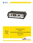
Vanguard SC and Vanguard 3000 Cellular Data Modem & IP Router Series
User Manual
001-7300-100
Revision 0; April 2012
Copyright Notice
©2011 CalAmp. All Rights Reserved.
CalAmp reserves the right to modify the equipment, its specification or this manual without prior notice, in the interest of
improving performance, reliability, or servicing. At the time of publication all data is correct for the operation of the
equipment at the voltage and/or temperature referred to. Performance data indicates typical values related to the
particular product.
No part of this documentation or information supplied may be divulged to any third party without the express written
consent of CalAmp. Products offered may contain software which is proprietary to CalAmp. The offer or supply of these
products and services does not include or infer any transfer of ownership.
Modem Use
The Vanguard SC and Vanguard 3000 Series modems are designed and intended for use in fixed and mobile applications.
“Fixed” assumes the device is physically secured at one location and not easily moved to another location. Please keep the
cellular antenna at a safe distance from your head and body while the modem is in use.
Important
Maintain a distance of at least 20 cm (8 inches) between the transmitter’s antenna and any person while in use. This
modem is designed for use in applications that observe the 20 cm separation distance.
Interference Issues
Avoid possible radio frequency (RF) interference by following these guidelines:
The use of cellular telephones or devices in aircraft is illegal. Use in aircraft may endanger operation and disrupt
the cellular network. Failure to observe this restriction may result in suspension or denial of cellular services to the
offender, legal action or both.
Do not operate in the vicinity of gasoline or diesel-fuel pumps unless use has been approved and authorized.
Do not operate in locations where medical equipment that the device could interfere with may be in use.
Do not operate in fuel depots, chemical plants, or blasting areas unless use has been approved and authorized.
Use care if operating in the vicinity of protected personal medical devices, i.e., hearing aids and pacemakers.
Operation in the presence of other electronic equipment may cause interference if equipment is incorrectly
protected. Follow recommendations for installation from equipment manufacturers.
Mobile Application Safety
Do not change parameters or perform other maintenance of the Vanguard SC modem and Vanguard 3000 while
driving.
Road safety is crucial. Observe National Regulations for cellular telephones and devices in vehicles.
Avoid potential interference with vehicle electronics by correctly installing the Vanguard SC modem. CalAmp
recommends installation by a professional.
UL Listed models only
When operating at elevated temperature extremes, the surface may exceed +70 Celsius. For user safety, the
Vanguard should be installed in a restricted access location.
The SIM/SVC connectors are used for maintenance purposes only. WARNING – EXPLOSION HAZARD, do not
connect while circuit is live unless area is known to be non-hazardous.
3
Revision History
2012 April
Rev 0
Initial Release
4
Table of Contents
1
Product Overview ................................................................................................................................................................ 8
1.1
Module Identification ................................................................................................................................................. 9
1.2
Features and Benefits for vanguard sc ....................................................................................................................... 9
1.3
Features and Benefits for vanguard 3000 ................................................................................................................ 10
1.4
General Specifications .............................................................................................................................................. 11
1.5
Mechanical Specifications ........................................................................................................................................ 12
1.6
Order Informaiton .................................................................................................................................................... 12
1.7
External Connectors ................................................................................................................................................. 13
1.8
Antenna .................................................................................................................................................................... 15
1.9
power cable pinout .................................................................................................................................................. 16
1.10
RS-232 Serial Port Integration Parameters .............................................................................................................. 16
1.10.1
2
3
ODP (Open Developers Platform) over RS-232 ............................................................................................... 17
Getting Started .................................................................................................................................................................. 17
2.1
Package Contents ..................................................................................................................................................... 17
2.2
Device Connections .................................................................................................................................................. 17
2.3
LAN Configuration .................................................................................................................................................... 17
2.4
Cellular connections ................................................................................................................................................. 18
2.4.1
GSM Users ............................................................................................................................................................ 18
2.4.2
CDMA Users ......................................................................................................................................................... 18
Vanguard SC and 3000 Web Interface ............................................................................................................................... 19
3.1
Unit Status ................................................................................................................................................................ 20
3.1.1
Status ................................................................................................................................................................... 20
3.1.2
Identity ................................................................................................................................................................. 27
3.1.3
Basic Settings ....................................................................................................................................................... 28
3.2
Cell Connection – VANGUARD SC ............................................................................................................................. 30
3.2.1
Dial Settings (GSM Models) ................................................................................................................................. 30
3.2.2
SIM Settings (GSM MODELS) ............................................................................................................................... 31
3.2.3
Dial Settings (CDMA Models) ............................................................................................................................... 34
3.2.4
Provisioning Status (CDMA MODELS) .................................................................................................................. 35
3.2.5
Provisioning Profiles (CDMA MODELS) ................................................................................................................ 39
3.3
Cell Connection – VANGUARD 3000......................................................................................................................... 42
3.3.1
Carrier .................................................................................................................................................................. 42
3.3.2
UMTS Settings ...................................................................................................................................................... 43
3.3.3
CDMA Settings ..................................................................................................................................................... 45
5
3.3.4
System Monitor ................................................................................................................................................... 48
3.3.5
Dynamic DNS........................................................................................................................................................ 51
3.4
LAN Settings ............................................................................................................................................................. 52
3.4.1
MAC Filtering ....................................................................................................................................................... 56
3.4.2
IP Filtering ............................................................................................................................................................ 58
3.5
WLAN Settings .......................................................................................................................................................... 61
3.5.1
Main ..................................................................................................................................................................... 61
3.5.2
Client .................................................................................................................................................................... 62
3.5.3
Access Point ......................................................................................................................................................... 64
3.5.4
Stats ..................................................................................................................................................................... 66
3.5.5
Site Survey ........................................................................................................................................................... 66
3.6
Router....................................................................................................................................................................... 67
3.6.1
Port Forwarding ................................................................................................................................................... 67
3.6.2
Static Routes ........................................................................................................................................................ 69
3.7
Security ..................................................................................................................................................................... 70
3.7.1
Status ................................................................................................................................................................... 70
3.7.2
PPTP ..................................................................................................................................................................... 71
3.7.3
IPSec ..................................................................................................................................................................... 72
3.7.4
GRE ....................................................................................................................................................................... 76
3.8
Serial ......................................................................................................................................................................... 77
3.8.1
External Serial ...................................................................................................................................................... 77
3.8.2
Internal Serial ....................................................................................................................................................... 83
3.9
GPS ........................................................................................................................................................................... 84
3.9.1
AAVL ..................................................................................................................................................................... 84
3.9.2
Settings ................................................................................................................................................................ 87
3.9.3
Status ................................................................................................................................................................... 88
3.10
Diagnostics ............................................................................................................................................................... 89
3.10.1
SNMP ............................................................................................................................................................... 89
3.10.2
Logging............................................................................................................................................................. 91
3.11
I/O Settings ............................................................................................................................................................... 93
3.11.1
Status ............................................................................................................................................................... 93
3.11.2
Settings ............................................................................................................................................................ 94
3.11.3
Labels ............................................................................................................................................................... 97
3.12
Firmware Update ..................................................................................................................................................... 98
6
4
IP Addressing ................................................................................................................................................................... 100
4.1
Overview ................................................................................................................................................................ 100
4.2
IP Addressing Tutorial ............................................................................................................................................ 100
4.3
Private versus Public IP Addresses ......................................................................................................................... 101
4.4
Port Forwarding ..................................................................................................................................................... 101
4.5
DMZ ........................................................................................................................................................................ 102
4.6
Friendly IP Address ................................................................................................................................................. 102
5
IPSec and VPN Pass-Through Deployment Guide ............................................................................................................ 102
6
Benefits of IPSec .............................................................................................................................................................. 103
7
Configuration summary ................................................................................................................................................... 103
7.1
7.1.1
CISCO Router – VPN Server Configuration Example .......................................................................................... 104
7.1.2
Vanguard SC – IPSec CLient Configuration Example .......................................................................................... 106
7.2
7.2.1
8
9
Case#1: Vanguard configured IPSEC Client ............................................................................................................ 104
Case#2: Vanguard configured VPN Pass-Through .................................................................................................. 107
Vanguard – VPN Pass-through Configuration example ..................................................................................... 107
User I/O Port .................................................................................................................................................................... 108
8.1
Input Circuit for Analog Inputs ............................................................................................................................... 110
8.2
Simplified Circuit for Digital Input/Outputs ........................................................................................................... 110
8.3
Simplified Circuit for Mechanical Relays ................................................................................................................ 110
8.4
Inserting Wires Into User Port Connector .............................................................................................................. 111
Service and Support ......................................................................................................................................................... 112
Appendix A – Abbreviations .................................................................................................................................................... 113
Appendix B – Warranty Statement .......................................................................................................................................... 114
7
1
PRODUCT OVERVIEW
The Vanguard SC Series from CalAmp is the ideal solution for a wide range of cellular data network serial and Ethernet
connectivity requirements.
CDMA models feature EV-DO Rev A speeds with data rates up to 3.1 Mbps downlink and 1.8 Mbps uplink and are backward
compatible to EV-DO Rev 0 and 1xRTT dependant on carrier service availability. This occurs automatically to the level of
service available. Dual Band Digital CDMA 800 MHz and CDMA PCS 1900 MHz models supports packet-switched services.
GSM models feature Tri-Band UMTS/HSUPA (850/1900/2100) and Quad-Band GSM/GPRS network support with data rates
up to 7.2 Mbps downlink and 2.0 Mbps uplink for HSPA and are backwared compatible to HSUPA, HSDPA, EDGE and GPRS
dependent on carrier service availability.
The Vanguard 3000 Series from CalAmp is the ideal solution for a wide range of cellular data network serial and Ethernet
connectivity requirements. All Vanguard 3000 models feature both high-speed 3G HSPA and EVDO cellular communications
in a single device with full GSM and CDMA backward compatibility. Vanguard 3000 delivers two LAN, one serial and Rx
diversity connections.
Mobile models feature an added 16-channel GPS receiver and a WiFi client and access point.
8
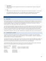
1.1
MODULE IDENTIFICATION
Vanguard SC
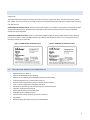
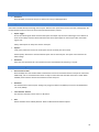
The module identification label can be found on the bottom of your Vanguard SC device. This label contains the product
part number, the serial number, FCC and IC IDs as well as carrier specific information that will be required when activating
your data account.
CDMA module identification labels contain the device ESN numbers. This number is required by your cellular carrier when
activating your data contract. The ESN number is provided in both decimal and Hex formats. The format required for
activation is carrier dependent.
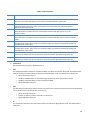
GSM module identification lables contain an International Mobile Equipment Identity (IMEI) number shown in decimal
format. This number is used by the GSM network only to identify and validate the device. It has no permanent or semipermanent relation to the subscriber.
Figure 1: CDMA Module Idenficiation Label
1.2
Figure 2: GSM Module Idenficiation Label
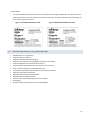
FEATURES AND BENEFITS FOR VANGUARD SC
Supports Dynamic or Static IP
Inbound and Outbound Ethernet Routing
DHCP Server and Inbound port mapping/translation (Port Forwarding)
Firewall configuration for increased network security
Diversity antenna port/auxiliary port for increased receive sensitivity
Local or remote configuration using HTML web server
TCP/IP Packet assembler and dis-assembler for serial connected devices
Inbound IP termination with Static IP
Modem Domain Names with Dynamic DNS
Embedded Linux on ARM 9 processor
Internet access and web browsing via Ethernet connector
VPN support
On-board 1.8/3V SIM socket (Active only for GSM Models)
9
Vanguard 3000
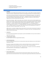
The module identification label can be found on the bottom of your Vanguard 3000 device. This label contains the
product part number, the serial number, FCC and IC IDs as well as carrier specific information that will be required
when activating your data account.
Figure 3: Fixed Model Idenficiation Label
1.3
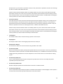
Figure 4: Mobile Model Idenficiation Label
FEATURES AND BENEFITS FOR VANGUARD 3000
Multiple carriers in a single device
Supports Dynamic or Static IP
Inbound and Outbound Ethernet Routing
DHCP Server and Inbound port mapping/translation (Port Forwarding)
Firewall configuration for increased network security
Diversity antenna port/auxiliary port for increased receive sensitivity
Local or remote configuration using HTML web server
TCP/IP Packet assembler and dis-assembler for serial connected devices
Inbound IP termination with Static IP
Modem Domain Names with Dynamic DNS
Embedded Linux on ARM 9 processor
Internet access and web browsing via Ethernet connector
VPN support
On-board 1.8/3V SIM socket (Active only for GSM Models)
10
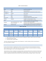
1.4
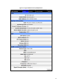
GENERAL SPECIFICATIONS
Product specifications are subject to change without notice.
Interface Connectors
RS-232 DE-9S Connector (DCE female)
10/100 Base-T Full Duplex (Dual)
10 Pin I/O Port
USB Client port
Power Connector
Molex 43045-4000 MicroFit 3.0, 4 pin header
LED Indicators
RSSI, SVC, NET, GPS, AUX
Size
Primary Antenna
50-ohm SMA Female
Diversity Antenna
50-ohm SMA Female
GPS Antenna
50-ohm, 3.3V SMA Female
WiFi Antenna
50-ohm RP-SMA Plug
4.5 (L) x 6.0 (W) x 1.9(H) inches (11.4 x 15.2 x 4.8 cm)
Weight
1.94lb (0.88 kg)
Power Input
9-28 VDC
Maximum TX Power
CDMA
GSM/EDGE
UMTS
25 dBm
33 dBm
24 dBm
Rx Sensitivity
CDMA
GSM/EDGE
UMTS
>-107 dBm
>-105 dBm
>-109 dBm
Frequencies
Cellular: TX: 824-849 MHz; Rx: 869-894 MHz
PCS: TX: 1850-1910 MHz; Rx: 1930-1990 MHz
Antenna Interface
Emissions
Operating: -30°C to +70°C 100% duty cycle. Note: Cellular TX power may be reduced outside
this range; Storage: -40° to +85°C (-40° to +185°F)
FCC Part 15b
Transport Protocols
UDP/TCP
Command Protocol
Web Interface
Temperature
11
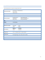
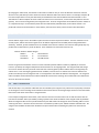
1.5
MECHANICAL SPECIFICATIONS
The following section describes in detail the exterior dimensions of the Vanguard SC modems and how to utilize the
mounting flanges to secure the modem to any surface, which can be drilled for such a purpose. The drawings may be used
as layout reference, but it is advised that a physical comparison be made to the modem before proceeding with the
mounting process.
Figure 5: Vanguard SC Mechanical Drawing
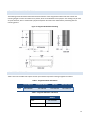
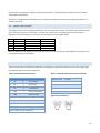
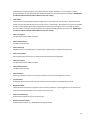
1.6
ORDER INFORMAITON
Table 1 shows the available order options and the part numbers required for ordering Vanguard SC modems.
Table 1 - Vanguard SC Order Information
HSPA
Carrier Options
STANDARD MODELS
ADD GPS
ADD GPS + WI-FI
GSM CARRIERS
140-7206-000
140-7206-010
140-7206-110
Table 2 - Vanguard 3000 Order Information
MODELS
FIXED
140-7230-000
MOBILE (GPS + WIFI)
140-7230-110
12
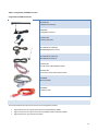
Table 3 - Vanguard SC and 3000 Accessories
Vanguard SC and 3000 Accessories
401-7500-001
4” Rubber Duck Antenna
L2ANT0003
3” Mag Mount Antenna
150-7001-005
110 VAC Input Power
401-7100-003 for 3000 only
GPS SMA Mag Mount Antenna
401-7100-004 for 3000 only
WiFi Mag Mount Antenna
150-7001-002
22 FT DC Power Cable (Mobile models)
150-7001-004
6 FT DC 3wire Power Cable (Fixed models)
L2CAB0002
DB-9 Serial Cable
L2CAB0006
7’ Ethernet cable
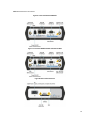
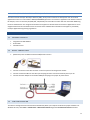
1.7
EXTERNAL CONNECTORS
This section describes the external connectors for the Vanguard SC modem.
Figure 6 shows the front panel connections for Standard (Fixed) models.
Figure 7 shows the front panel connections for Mobile models with GPS and WiFi.
Figure 8 shows the rear panel for all models.
13
Table 4 describes these connections.
Figure 6: Front Panel Standard Models
Figure 7: Front Panel Mobile Models with GPS and WiFi
Figure 8: Rear Panel Connections
14
Table 4 - External Connectors
Panel Indicator
Connection
Description
COM
RS-232
Serial to IP conversion use
ANT
SMA
Primary RF Antenna
AUX (Figure 4)
SMA
Cellular Diversity or Cellular/GPS combination antenna
AUX (Figure 5)
RP-SMA
Wi-Fi antenna
GPS
SMA
GPS Antenna
DIV
SMA
Cellular Diversity Antenna
LAN 1, LAN 2
RJ-45
Interface for Ethernet connection to devices
SIM/SVC
USB Mini
Available for CalAmp Support Use Only
PWR Jack
Molex 43025-0400; Power – bottom
pins; I/O – top pins
SIM/SVC
SIM Card socket
Hold for one second to reset unit. If held for at least 4 sec,
unit will reconfigure to factory default settings.
Interface for power plug (9-28VDC)
Interface for Input and Output control lines; ODP use only.
Interface for SIM card. Your wireless service provider will
supply the SIM card with your wireless service contract.
RESET
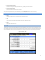
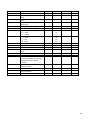
Table 5 - Status LEDs
Function
Off
Green
RSSI
Strong
SVC
3G
NET
GPS
No
Connectivity
Disabled
Fix
Aux
Disabled
Good
Flash Green
Red
Flash Red
Weak/None
Flash Amber
Medium
3G/NC
NC
RX Data
TX Data
Search
Amber
2G
2G/NC
RX/TX
No Fix
Failed
If SVC is solid, then modem is connected to internet. If flashing, the modem is trying to connect to the network.
Net indicates direction of data.
Aux refers to WiFi in mobile models.
The LEDs act different than the table at boot. The boot sequence is: All Red, All Amber, All Green, All Flash Green 3
times. Boot sequence is complete.
1.8
ANTENNA
Primary antenna connections are SMA female connectors and must be used with antenna with SMA male connectors.
When using a direct mount or rubber duck antenna, choose the antenna specific to your band requirements. Mounting
options and cable lengths are user’s choice and application specific.
The AUX antenna connector is installed on all standard models and can be used for Diversity or True GPS. The diversity port
supports three bands, Cellular (850 MHZ), PCS(1900 MHZ), and GPS(1575 MHZ). Connect a dual band cellular antenna to
this port to implement RX diversity on the unit and increase receive sensitivity on the cellular network. Connect a GPS
15
antenna, with an average gain >-5dBi, if using the GPS functionality. If both RX diversity and GPS are required, install a
Cellular/GPS combo antenna.
This device is configured with default settings and is ready to be configured via HTML. Some configurations may be set
using AT commands.
1.9
POWER CABLE PINOUT
Depending on the version of Vanguard ordered there are two possible power cables. The mobile version ships with a 22FT
power cable that requires a fuse (included). The fixed version ships with a 6 ft cable that does not require a fuse.
Regardless of the cable length, the pinout is the same though the wire colors differ slightly.
Pin
1
2
3
4
Signal
VIN/VBatt
Ground
Ignition Sense
No Connect
Color Mobile
Red
Blue
White
NA
Color Fixed
Red
Black
White
NA
When installed for a fixed application or if the Ignition sense line is not required in a mobile application, the ignition sense
line should be shorted to Vin/Vbattery.
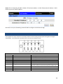
1.10 RS-232 SERIAL PORT INTEGRATION PARAMETERS
Table 6 provides the serial cable design information to integrate the Vanguard SC modem into your system. Table 7 gives
the default RS-232 communication parameters.
Table 6 - Standard RS-232 DE-9 Pin out
Pin
Name
1
CD
2
Direction
Table 7 - Default RS-232 Communication Parameters
Description
Bits Per Second
115,200
←
Carrier Detect
Data Bits
8
RX
←
Receive Daa
Parity
None
3
TX
→
Transmit Data
Stop Bits
1
4
DTR
→
Data Terminal Ready
Flow Control
None
5
GND
6
DSR
←
Data Set Ready
7
RTS
→
Request to Send
8
CTS
←
Clear to Send
9
RI
←
Ring Indicator
System Ground
Figure 9: DE-9 Connectors
Note: Direction is DTE relative DCE
16
1.10.1 ODP (OPEN DEVELOPERS PLATFORM) OVER RS-232
This device includes the Open Developers Platform (ODP), which permits customers to develop their own Linux based
applications which run on the modem’s ARM9 (AT91RM9200) processor. The customer’s application can utilize the external
RS-232 port, and or an internal 3 pin (GND, RXD, TXD) RS-232 port and is able to transfer data over the cellular WAN using
the linux socket libraries. The Vanguard SC firmware also supports an API that allows the customer’s application to access
diagnostic data from the cell module such as connection status and RSSI. More information and support is provided by
CalAmp’s Applications Engineering organization.
2
GETTING STARTED
2.1
PACKAGE CONTENTS
2.2
2.3
Vanguard SC or 3000 Modem
Power Cable
Information Card
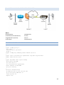
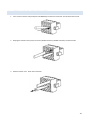
DEVICE CONNECTIONS
1.
(GSM Users) Insert the SIM card into the SIM/SVC slot as shown.
2.
3.
4.
Connect an antenna to the ANT connector on the front panel of the Vanguard SC modem.
Connect an Ethernet cable into the LAN 1 port and plug the other end into the network port of your PC.
Connect the Power Adapter to the modem PWR port and plug into a proper AC power socket.
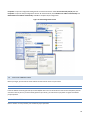
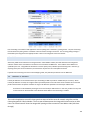
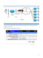
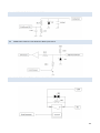
LAN CONFIGURATION
This device is configured via the Internet which automatically allows your computer to obtain the proper IP address. For
Windows XP users, select Start » Control Panel » Network Connections. Right click Local Area Connection and select
17
Properties to open the configuration dialog box for Local Area Connection. Select Internet Protocol (TCP/IP) and click
Properties to open the TCP/IP configuration window. On the General tab, select Obtain an IP address automatically and
Obtain DNS server address automatically. Click OK to complete TCP/IP configuration.
Figure 10: LAN Configuration Screens
2.4
CELLULAR CONNECTIONS
Before you begin, you will need an active Cellular account with the carrier of your choice.
2.4.1 GSM USERS
Insert the SIM card with the gold side up into the SIM/SVC slot in the rear of the device. Push the card completely into the
slot until it clicks in place. If you have already powered your device, you will need to cycle power to register the SIM for
proper operation.
2.4.2 CDMA USERS
Refer to Section 3.2.3 to provision your modem for proper operation.
18
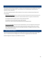
3
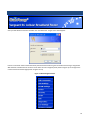
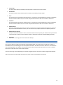
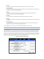
VANGUARD SC AND 3000 WEB INTERFACE
Start your web browser and enter 192.168.1.50 in the address bar. A login screen should appear.
Enter the User Name: admin and the Password: password and click OK to log into the modem’s Home Page. Vanguard SC
Web interface is divided into two sections. On the left is the main navigation panel (shown in Figure 9). On the right is the
content area for the desired page (shown in Figures 10-11).
Figure 11: Main Navigation Panel
19
3.1
UNIT STATUS
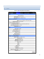
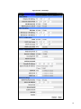
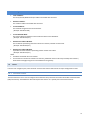
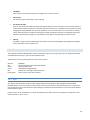
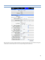
3.1.1 STATUS
Figure 12: Vanguard SC CDMA Unit Status Window
20
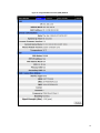
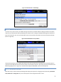
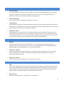
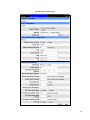
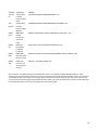
Figure 13: Vanguard 3000 Unit Status (GSM) Window
21
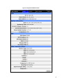
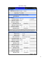
Figure 14: Vanguard SC GSM Unit Status
22
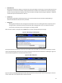
Figure 15: Vanguard 3000 Unit Status (CDMA) Window
23
LAN
IP
Displays LAN side static IP information for this device (the modem). Note: Once this IP address has been changed
and saved, the browser connection to the device will be lost. To continue configuration, please connect to the
(new) IP address / the address that has been entered and saved.
Subnet Mask
Displays the LAN side subnet mask for the modem
MAC Address
Media Access Control Address. Every Ethernet device (i.e. LAN cards) has a unique hardware serial number or MAC
address to identify each Network Device from all others.
System Information
Date
Displays the current date and time (UTC) as received from the cellular carrier. The date and time information is
updated at the start of each PPP connection, and then maintained internally until the modem is rebooted. If no
PPP connection has been made this boot cycle, the time display will not be accurate. This is not a user settable
function – it is controlled only by the carrier supplied date and time. Not all carriers support this function.
System Up time
Displays the system uptime in seconds:
― 1 minute = 60 seconds
― 1 hour = 3600 seconds
― 1 day = 86400 seconds
― 1 year = 31,536,000 seconds
Current Firmware Version
Displays the current modem firmware version loaded. Please visit www.calamp.com for the latest updates.
Kernel Date
Displays the date of the operating system kernel the unit is running
Phone Module Version
This will vary depending on the vendor of the radio module inside the modem.
Temperature
Displays the current internal temperature of the modem, as measured by the cellular radio module.
PPP Status
Indicates the status of the cellular connection, usually UP when connected properly.
PPP
24
PPP IP Address
The current IP address of the Vanguard on the cellular network.
PPP Subnet Mask
The current Subnet Mask of the Vanguard on the cellular network.
PPP P-t-P
The “point-to-point” address of the gateway on the cellular network, It may be possible to ping this address to
determine if a PPP IP Address assigned is routable from the Internet.
Primary DNS
The Primary DNS server, as assigned by the cellular carrier, when PPP is UP.
Secondary DNS
The Secondary DNS server, as assigned by the cellular carrier, when PPP is UP.
CDMA Connection Status
Service Type
Determines the type of network your device has connected to; GPRS, EDGE, UMTS, HSDPA, CDMA 1xRTT, EVDO
Rev0 or RevA.
ESN
The Electronic Serial Number is only applicable for the CDMA product line, carrier specific (Alltel, Verizon, Sprint,
etc).
MDN/MTN
The actual phone number of the device as supplied by the carrier. When the unit is successfully provisioned, the
phone number for the user account will be displayed.
MIN/IMSI
This number is used by the Mobile Telephone Network and will be different if ported from another carrier (not
used by end user of device).
PRL
Preferred Roaming List, only applicable for the CDMA product line, carrier specific (AllTel, Verizon, Sprint, etc).
SID
System ID (Identity), provided by the Carrier.
NID
Network Identifier, this is supplied automatically from the network.
Channel
Cell Site channel number at which the modem is connected and is useful for the carrier in the event of
troubleshooting.
25
Frequency
Cellular frequency band the modem is using, 800MHz and 1900MHz are mainly in the US and outlying areas. In
some cases 900 and 1800 will be seen for European or Foreign carriers.
Roaming
Options are either Roaming or Not Roaming and may defer from the PRL in the case of CDMA.
Signal Strength (dBm)
Measured in dBm, this is the Received Signal Strength Indicator (RSSI).
Diagnostic
If less than 128, this is the number of successful PPP connections since the modem was rebooted. If 128 or
greater, the formula Diagnostic value – 128 = the number of times the cellular module has been reset since the
modem was rebooted.
GSM Connection Status
Service Type:
Determines the type of network your device has connected to; GPRS, EDGE, HSDPA, HSUPA, or HSPA. "Check SIM"
will be displayed if the SIM is invalid, missing, or if the PIN needs to be entered.
MDN:
The Mobile Directory Number is the phone number assigned to the SIM card supplied by the carrier. The MDN
may display “NOT AVAILABLE” if the PIN status is disabled or the MDN is unknown.
IMEI:
The International Mobile Equipment Identity is a unique 15-digit number that serves as the serial number of the
GSM module in the modem.
IMSI:
The International Mobile Subscriber Identity is a unique number which designates the subscriber. This number is
used for provisioning in network elements. The IMSI may display “NOT AVAILABLE” if a SIM card is not detected.
Country:
Country name or code associated with the GSM network.
Carrier:
Cellular provider name or code.
Cell ID:
Network Identifier, this is supplied automatically from the network.
Channel:
Cell Site channel number at which the modem is connected and is useful for the carrier in the event of
troubleshooting.
Frequency:
Cellular frequency band the modem is using, 800MHz and 1900MHz are mainly in the US and outlying areas. In
some cases 900 and 1800 will be seen for European or Foreign carriers.
26
Roaming:
Options are either Roaming or Not Roaming.
Signal Strength (dBm):
Measured in dBm, this is the Received Signal Strength Indicator (RSSI).
Diagnostic:
If this number is less than 128, it is the number of PPP connections made since the last reboot of the modem. If
this number is 128 or more, the formula 128-Diagnostic value equals the number of times the cellular radio
module has been reset.
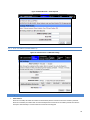
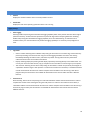
3.1.2 IDENTITY
Figure 16: Unit Status – Identity
Factory Settings
Serial Number:
Unique serial number for this unit.
Model Number
Unit model number defining its capacity and features.
User-defined
Unit ID
User-defined for ease of reference, used by various services.
27
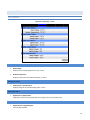
3.1.3 BASIC SETTINGS
Figure 17: Unit Status – Basic Settings
Vanguard SC
Vanguard 3000
Unit ID
ID
This identification number serves to distinguish this unit from other units in the network. It is at the same time the
TAIP identification for GPS reporting and serves as the 'syslocation' for the SNMP facility.
28
Power Management
ID
This identification number serves to distinguish this unit from other units in the network. It is at the same time the
TAIP identification for GPS reporting and serves as the 'syslocation' for the SNMP facility.
Power Management
The Vanguard 3000 unit is designed to stay ON even if the ignition is turned off. The unit can be configured to automatically
shut down 1, 5, 30, 60 or 240 minutes after ignition has been turned off or when the supply voltage drops to a certain level.
Shutdown Method
Disabled by default. Select "Power off" to enable power management.
After Ignition Line Off
Select between the following time intervals: 1, 5, 30, 60 or 240 minutes.
When Voltage Drops Below
Enter desired voltage. Enter "0" to disable (and give precedence to time delay configured under "After ignition
time off").
Network Time
The Vanguard 3000 is capable of maintaining the current time (UTC) by synchronizing itself with a Network Time Protocol
(NTP) Server. The user may specify a server URL and how frequently the router should synchronize with the server. The
router must have an internet connection to synchronize with the server. The router does not save/track time while
powered off, so time will be inaccurate until the router can connect with the server.
NTP Client
Disabled by default. Select Enabled to activate the router’s NTP client to synchronize with the specified server.
NTP Server
Enter the URL of the desired NTP Server. Most NTP Servers have a posted usage policy. A review usage policies
and the choice of an appropriate server is recommended.
Update Frequency
Set to 24 hours by default. Specify the frequency to synchronize the router time with the specified NTP Server.
29
3.2
CELL CONNECTION – VANGUARD SC
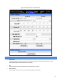
3.2.1 DIAL SETTINGS (GSM MODELS)
Figure 18: Cell Connection – GSM Dial Settings
Dial Settings
Auto Connect:
When set to Enable, will allow the modem to automatically dial the connection when the modem is powered.
When set to Disable, the modem will not automatically dial the connection to the cellular provider and will not
attempt to automatically re-connect when the connection has dropped.
GSM Band:
This selection is used to configure the modem to operate on a set of frequency bands.
o ALL – All available bands will be accessible, commonly called autoband. (Default)
o WCDMA 2100 – Uses the 2100MHz frequency band in UMTS/HSDPA networks.
o EGSM – Uses the 900/1800 MHz European GSM frequency band.
o ALL GSM – Can use any available GSM frequency band, Europe 900/1800 MHz or USA 850/1900 MHz.
o ALL WCDMA – Can use any available WCDMA frequency band, 850/900/2100 MHz in UMTS/HSDPA
networks.
30
Carrier APN:
The Access Point Name provided by the cellular provider required to access the network.
Dial Number:
The phone number used to initiate a data connection to the cellular provider via PPP.
User:
Sets the username required by the cellular provider. Leave blank if not required.Warning: If used in combination
with this modem's VPN Server, this username and password will also be valid on this modem's VPN Server.
Password:
Sets the password required by the cellular provider. Leave blank if not required.Warning: If used in combination
with this modem's VPN Server, this username and password will also be valid on this modem's VPN Server.
Authentication:
Selects the authentication protocol used. If Auto is selected, the Vanguard will automatically select a protocol. If
Only Protocols Selected Below is chosen, then the router will only accept requests for the specified protocols.
Authentication Protocols:
If Only Protocols Selected Below is chosen, then these fields are used to specify each Authentication protocol that
router will accept. At least 1 must be selected. If Auto is selected, these choices will be disabled (greyed out).
Dial Status:
Click "view" to see a log from the last connection attempt.
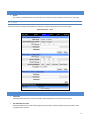
3.2.2 SIM SETTINGS (GSM MODELS)
One of the key features of GSM is the Subscriber Identity Module (SIM), commonly known as a SIM card. The SIM is a
detachable smart card containing the user's subscription information. This allows the user to retain his or her information
after switching handsets. The SIM has a security feature which, when enabled, will require the user to enter a valid PIN
before the modem will connect to the cellular network.
From the Home page, select SIM Settings from the left navigation panel to confirm the modem recognized the SIM card.
SIM STATUS should read ACCEPTED. PIN STATUS may show the PIN to be DISABLED or ACCEPTED.
31
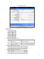
Figure 19: Cell Conection – SIM Settings
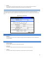
3.2.2.1 ENABLING PIN SECURITY
As shown in the previous section, the default setting for PIN Security is disabled. Before enabling the PIN Security feature,
make sure you have the PIN number provided by your wireless carrier. Change the Disable PIN setting from Yes (shown in
Figure 19) to NO. Enter your carrier provided PIN into the Current PIN field. Click SAVE to access the PIN Security Settings
(shown in Figure 20).
Figure 20: PIN ACCEPTED Security Enabled
The PIN security feature is now enabled. PIN STATUS shows that the PIN has been ACCEPTED. Each time modem power is
cycled, the proper PIN will need to be entered in order for the modem to dial out. Upon restart, the PIN is entered from the
SIM Settings page (shown in Figure 21). The PIN STATUS displays PIN REQUIRED, Enter PIN 3 attempts left.
3.2.2.2 PIN SECURITY OPTIONS
After PIN security has been enabled, the SIM page will display three options for changing the PIN functionality, Remember
PIN, Disable PIN, or Change PIN. Only one of these options can be changed and saved at a time.
32
Remember PIN:
Selecting YES will allow the modem to remember the security PIN making it unnecessary to enter the PIN each time the
modem tries to connect to the network. Selecting NO will set the modem to not remember the current PIN, requiring
the user to enter the PIN when requested. Since only the modem remembers the PIN, using the SIM card in a different
modem will require PIN authorization to dial out.
Disable PIN:
Selecting YES will disable the PIN security feature; the current PIN will need to be entered to allow disabling. A
selection of NO indicates that PIN security is enabled.
Change PIN:
Selecting YES will allow the user to change the current PIN to a new one. Selecting NO will not require the user to
change the PIN in the New PIN and Confirm PIN fields. When changing PINs, the user is required to input the
current PIN, the new PIN, and the new PIN again in the fields provided.
After one of the options is changed, click the SAVE button to refresh the page showing the changes.
Figure 21: SIM Settings for PIN Required
At this point the user has 3 attempts to enter the correct PIN. If the correct PIN is not entered after 3 attempts, an unlock
code or PIN Unblocking Key (PUK) from the service provider will be required before the SIM card is usable again. Figure 22
shows the SIM settings after an incorrect PIN has been entered.
Figure 22: SIM PIN Rejected
Figure 23 shows the SIM page requiring the unlock code to be entered. At this point the user has 10 attempts to enter the
correct unlock code or the SIM card will be rendered unusable.
33
Figure 23: SIM PIN Unlock – Code Required
3.2.3 DIAL SETTINGS (CDMA MODELS)
Figure 24: Cell Connection – CDMA Dial Settings
Dial Settings
Auto Connect:
When set to Enable, will allow the modem to automatically dial the connection when the modem is powered.
When set to Disable, the modem will not automatically dial the connection to the cellular provider and will not
attempt to automatically re-connect when the connection has dropped.
34
Dial Number:
The phone number used to initiate a data connection to the cellular provider via PPP. The default dial number is
#777.
User:
Sets the username required by the cellular provider. Leave blank if not required.Warning: If used in combination
with this modem's VPN Server, this username and password will also be valid on this modem's VPN Server.
Password:
Sets the password required by the cellular provider. Leave blank if not required.Warning: If used in combination
with this modem's VPN Server, this username and password will also be valid on this modem's VPN Server.
Authentication:
Selects the authentication protocol used. If Auto is selected, the Vanguard will automatically select a protocol. If
Only Protocols Selected Below is chosen, then the router will only accept requests for the specified protocols.
Authentication Protocols:
If Only Protocols Selected Below is chosen, then these fields are used to specify each Authentication protocol that
router will accept. At least 1 must be selected. If Auto is selected, these choices will be disabled (greyed out).
Dial Status:
Click "view" to see a log from the last connection attempt.
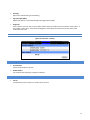
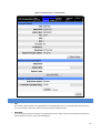
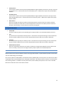
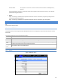
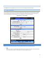
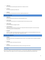
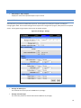
3.2.4 PROVISIONING STATUS (CDMA MODELS)
When a new modem is powered up for the first time, most of the provisioning information is blank or has information that
needs to be changed. The device is usually shipped with the radio ready to be provisioned on a cellular carrier’s network.
Features called Over-The-Air Service Provisioning (OTASP) and Internet Over-The-Air (IOTA) are supported, which allow the
cellular providers to program the modem with specific information to activate the account.
35
Figure 25: Cell Connection – Provision Status
Current Status
ESN:
The Electronic Serial Number is only applicable for the CDMA product line, carrier specific (Alltel, Verizon, Sprint,
etc). This number is used to set up the user account with the cellular provider.
MDN/MTN:
The actual phone number of the device as supplied by the carrier. When the unit is successfully provisioned, the
phone number for the user account will be displayed.
36
MIN/IMSI:
This number is used by the Mobile Telephone Network and will be different if ported from another carrier (not
used by end user of device).
PRL:
Preferred Roaming List, only applicable for the CDMA product line, carrier specific (Alltel, Verizon, Sprint, etc).
SID:
System ID (Identity), provided by the Carrier.
NID:
Network Identifier, this is supplied automatically from the network.
Channel:
Cell Site channel number to which the modem is connected. This number can be useful to the cellular provider for
troubleshooting purposes.
Frequency:
Cellular frequency band the modem is using, 800MHz and 1900MHz are mainly in the US and outlying areas. In
some cases 900 and 1800 will be seen for European or Foreign carriers.
Roaming:
Options are either Roaming or Not Roaming and may defer from the PRL in the case of CDMA. For provisioning,
the unit must NOT be roaming.
Signal Strength (dBm):
Measured in dBm, this is the Received Signal Strength Indicator (RSSI). For provisioning, the signal strength should
be greater than -95 dBm.
Manual-Entry Activation
MDN/MTN:
The Mobile Directory Number assigned by the cellular provider for the specific ESN on the user account.
MSID/IMSI:
MSID, which only needs to be entered if different than the MDN.
Unlock Code:
A carrier supplied activation code (usually 6 or 7 digits for Sprint accounts).
Click the Write MDN/MSID button when the required information has been entered.
Enable/Disable OMA-DM Activation
This section will only be displayed for units which are capable of automatic (OMA-DM) provisioning. You may choose to
enable or disable the automatic provisioning and save your desired setting. If enabled, and the unit is not provisioned
(activated), each time at power-on (only) the unit will attempt an auto-activation. This capability is dependant on whether
or not it is offered by your cellular carrier.
37
Auto-Activation:
Choose Enable to direct an unprovisioned unit to attempt OMA-DM activation once per power-up.
Click the SAVE button to save your desired setting after making a change.
Manual Initiation of OMA-DM Provisioning
This section will only be displayed for units which are capable of automatic (OMA-DM) provisioning. The activation status is
displayed, and a button is provided to direct the unit to begin an OMA-DM provisioning attempt. Depending on changes to
your carrier's network, it may be necessary to re-provision a unit that has already been activated. The OMA-DM capability is
dependant on whether or not it is offered by your cellular carrier.
Activation Status:
Displays the activation status as Activated or Not Activated.
Click the OMA-DM button to trigger an OMA-DM provisioning attempt.
Activation Type
This section is displayed for units that are not capable of automatic (OMA-DM) provisioning. Availability of OMA-DM is
carrier dependant. For carriers that do not support OMA-DM, the provisioning process must be triggered by entering carrier
specific information and depressing the carrier specified button (OTASP or IOTA).
Command (OTASP Only):
The dial command used for provisioning the modem. For OTASP the number is *22899. For IOTA this field is left blank.
Click the OTASP button to start the provisioning process for units using Verizon.
Click the IOTA button to start the provisioning process for units using Sprint.
3.2.4.1 VERIZON WIRELESS PROVISIONING INFORMATION (OTASP)
Verizon features Over-The-Air Service Provisioning (OTASP) which allows the cellular provider to provision the modem.
Provisioning must occur in a non-roaming area of the Verizon network with a medium to strong signal strength.
Select Provisioning from the side menu bar.
Confirm the OTASP command reads *22899.
Click the OTASP button.
If unsuccessful, follow the steps below to enter the information manually. Periodically, you should locally or remotely make
sure to click on the OTASP button to ensure the PRL is updated. In some cases this may happen automatically by the carrier.
Manual-Entry Activation
If provisioning must occur in a roaming area, make sure to have a medium to strong signal strength because
manual-entry activation will be required.
Select Provisioning from the side menu bar.
Input the MDN/MTN and MSID/IMSI (MIN) given by your provider
Put 6 0’s (000000) for the unlock code
Click the Write MDN/MSID button.
38
3.2.4.2 SPRINT PROVISIONING INFORMATION (OMA-DM)
Sprint features Open Mobile Alliance Device Management (OMA-DM) which allows the cellular provider to provision the
modem.
After the account is activated by Sprint, the device will auto-provision after power is applied to the device for the first time.
First, verify on the Home page the MDN/MTN and MSID/IMSI/MIN are in the default mode. Then after 3-4 minutes, check
again that the MDN/MTN and MSID/IMSI/MIN are populated with the numbers provided by the carrier. Once this is
complete, you can move on to the next section. If auto-provisioning doesn’t occur, push the OMA-DM button to provision.
If both of these are unsuccessful, follow the steps below to deactivate auto-provisioning and enter the information
manually.
Provisioning must occur in a non-roaming area of the Sprint network with a medium to strong signal strength.
Select Provisioning from the side menu bar.
Sprint is capable of automatic OMA-DM provisioning. The Auto Activation can be Enabled or Disabled. To save the
Auto Activation, click the SAVE button.
If Auto Activation is Disabled, a manual initiation of OMA-DM can be started by clicking on the OMA-DM button
If the auto-provisioning fails, and OMA-DM manual provisioning fails, and your outside the Sprint network, follow
the manual-entry activation steps below.
Manual-Entry Activation
If provisioning must occur in a roaming area, make sure to have a medium to strong signal strength because
manual-entry activation will be required.
Select Provisioning from the side menu bar.
Input the MDN/MTN and MSID/IMSI (MIN) given by your provider.
Put in the unlock code given by your provider.
Click the Write MDN/MSID button.
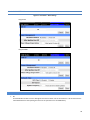
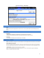
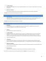
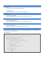
3.2.5 PROVISIONING PROFILES (CDMA MODELS)
The Provider NAI page supports the programming of 2 profiles that may be used to login to the cellular provider's network.
It also allows the user to choose which profile is active.A provider may support alternate networks whose use is limited to
specific customers. Login information must be gathered from the provider. Be aware that incorrect parameter settings
could result in no access to the standard network, and no access to the alternate network.
39
Figure 26: Cell Connection – Provision Profiles
Profile Settings
Profile Enable:
This field indicates if the profile is enabled. It is possible to enable both profiles. Whether to enable 1 or both
profiles should be based on information from the provider.
NAI:
This field should be set the the Network Access ID supplied by the provider.
Home IP Address:
This parameter should be set to the Home IP Address supplied by the provider.
40
Primary IP Address:
This parameter should be set to the Primary Home Agent IP Address supplied by the provider.
Secondary IP Address:
This parameter should be set to the Secondary Home Agent IP Address supplied by the provider.
MN-AAA SPI:
This parameter should be set to the MN-AAA SPI setting supplied by the provider. This is a numeric setting.
MN-HA SPI:
This parameter should be set to the MN-HA SPI setting supplied by the provider. This is a numeric setting.
Home Agent Secret:
This parameter should be set to the Home Agent Secret (password) supplied by the provider.
AAA Secret:
This parameter should be set to the AAA Shared Secret (password) supplied by the provider.
Reverse Tunneling:
Reverse Tunneling may be enabled or disabled, as specified by the provider.
Program:
Pressing the program button will prompt you to confirm you wish to program the current displayed settings. If
confirmed, the settings will be programmed and the unit will reboot.
Active Profile:
Displays which profile is active. The field cannot be modified, instead press the Change button to select the other
profile.
Switch Profile:
Pressing the Switch Profile button will prompt you to confirm you wish to switch to activate the other profile. If
confirmed, the other profile will be selected and the unit will reboot.
41
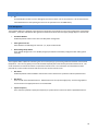
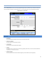
3.3
CELL CONNECTION – VANGUARD 3000
Select Cell Connection from the left navigation pane to access the carrier, UMTS, CDMA, system monitor and dynamic DNS
settings screen.
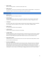
3.3.1 CARRIER
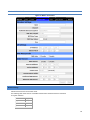
Figure 27: Cell Connection – Carrier
Carrier
Active Carrier
elects which carrier and credentials to use for data calls. The Secondary Carrier cannot be selected if it is “None”.
(Changing carriers takes time and the page may take up to one minute to refresh after Save is clicked.)
42
Primary Carrier
A list of carriers and their cellular protocols (UMTS/CDMA) and regions (Global, North America, Europe). Select the
appropriate carrier. It cannot be the same as the Secondary Carrier. UMTS carriers require that a proper SIM be
installed.
Secondary Carrier
A list of carriers and their cellular protocols (UMTS/CDMA) and regions (Global, North America, Europe) or None.
Select the appropriate carrier. It cannot be the same as the Primary Carrier. UMTS carriers require that a proper
SIM be installed.
Auto Connect
When set to Enable, will allow the modem to automatically dial the connection when the modem is powered.
When set to Disable, the modem will not automatically dial the connection to the cellular provider and will not
attempt to automatically re-connect when the connection has dropped.
Primary/Secondary Carrier
Carrier APN
This field is visible only when the corresponding carrier supports UMTS. Enter the APN provided by the carrier.
User
Sets the username required by the cellular provider. Leave blank if not required. Warning: If used in combination
with this modem's VPN Server, this username and password will also be valid on this modem's VPN Server.
Password
Sets the password required by the cellular provider. Leave blank if not required. Warning: If used in combination
with this modem's VPN Server, this username and password will also be valid on this modem's VPN Server.
Authentication Protocols
Selects the authentication protocol used. If Auto is selected, the Vanguard will negotiate a protocol with the cell
tower. If Use Only is chosen, then the Vanguard will only accept requests for the specified protocols.
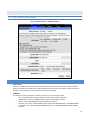
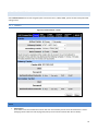
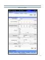
3.3.2 UMTS SETTINGS
When the Active Carrier supports UMTS, the fields on this page will be enabled. A specific Band of operation can be chosen
and various SIM settings can be changed.
One of the key features of GSM (UMTS) is the Subscriber Identity Module (SIM), commonly known as a SIM card. The SIM is
a detachable smart card containing the user's subscription information. This allows the user to retain his or her information
after switching handsets. The SIM has a security feature which, when enabled, will require the user to enter a valid PIN
before the modem will connect to the cellular network.
43
Figure 28: Cell Conection – UMTS Settings
Band Selection
Band
A list of frequency bands appropriate for the Active Carrier. Select a specific band or (recommended) select All
Bands.
Current Status
SIM STATUS
“SIM ACCEPTED” will display if a valid SIM card is inserted properly into the modem.
“NO SIM, Insert Valid SIM and Press Reset” will display if the SIM card is invalid or missing.
PIN STATUS
“PIN DISABLED” will display when the PIN security is not enabled.
Change PIN Status – Disable PIN
Action: “PIN disabled. To change it, it must be enabled first” will be displayed when the PIN security is not enabled.
Disable PIN (Enter Current PIN)
Select Yes to disable the PIN security feature. Select No to enable PIN security for the modem. After selecting No,
the current PIN should be entered in the Current PIN: field. Click on the Save button to finish enabling PIN security.
“PIN ACCEPTED” will display when the PIN security is enabled.
Action: You may change only one of the following 3 options at a time. Three choices are given to Remember,
Disable, or Change the PIN security settings.
44
Remember PIN (Enter Current PIN)
Selecting Yes will allow the modem to remember the security PIN making it unnecessary to enter the PIN each time
the modem tries to connect to the network. Selecting No will set the modem to not remember the current PIN,
requiring the user to enter the PIN when requested.
Disable PIN (Enter Current PIN)
Selecting Yes will disable the PIN security feature; the current PIN will need to be entered to allow disabling.
Selecting No will not disable the PIN security feature.
Change PIN (Enter Current PIN, New PIN, and Confirm PIN)
Selecting Yes will allow the user to change the current PIN to a new one. Selecting No will not require the user to
change the PIN in the New PIN and Confirm PIN fields. After changes have been made, click on the Save button to
finish.
“PIN Entry Required” will display when the PIN security is enabled and set not to remember the PIN.
PIN
A field is provided for the user to enter the valid PIN. The user will have a total of 3 opportunities to enter the
correct PIN.
“Unknown” will display if the SIM card is not detected.
“SIM Invalid” will be displayed if the SIM card is not detected.
Change PIN Status – PIN Entry
Current PIN
Field to enter the current valid PIN if PIN security is enabled. Also used to enable PIN security after the user selects
No to Disable PIN security.
New PIN
Field to enter the new PIN if PIN security is enabled.
Confirm New PIN
Field to enter and confirm the new PIN if PIN security is enabled.
3.3.3 CDMA SETTINGS
When the Active Carrier supports CDMA, the fields on this page will be enabled. A specific Band of operation can be chosen
and new modem can be provisioned.
When a new modem is powered up for the first time, most of the provisioning information is blank or has information that
needs to be changed. The device is usually shipped with the radio ready to be provisioned on a cellular carrier’s network.
Features called Over-The-Air Service Provisioning (OTASP) and Open Mobile Alliance Device Management (OMA-DM) are
supported, which allow the cellular providers to program the modem with specific information to activate the account.
45
Figure 29: Cell Connection – CDMA Settings
Band Selection
Band
A list of frequency bands appropriate for the Active Carrier. Select a specific band or (recommended) select All
Bands.
Current Status
MEID
The Mobile Equipment Identifier is used by the cellular carrier as the means to identify the cellular module. This is
the identifier is used to set up the user account with the cellular provider.
46
MDN/MTN
The actual phone number of the device as supplied by the carrier. When the unit is successfully provisioned, the
phone number for the user account will be displayed.
MIN/IMSI
This number is used by the Mobile Telephone Network and will be different if ported from another carrier (not
used by end user of device).
PRL
Preferred Roaming List, only applicable for the CDMA product line, carrier specific (Alltel, Verizon, Sprint, etc).
SID
System ID (Identity), provided by the Carrier.
NID
Network Identifier, this is supplied automatically from the network.
Channel
Cell Site channel number to which the modem is connected. This number can be useful to the cellular provider for
troubleshooting purposes.
Frequency
Cellular frequency band the modem is using, 800MHz and 1900MHz are mainly in the US and outlying areas. In
some cases 900 and 1800 will be seen for European or Foreign carriers.
Roaming
Will be either Roaming or Not Roaming. Roaming indicates service is being provided by an alternate carrier who
has a roaming agreement with your contracted carrier. While Roaming, additional charges may apply. For
provisioning, the unit must be Not Roaming.
Signal Strength (dBm)
Measured in dBm, this is the Received Signal Strength Indicator (RSSI). For provisioning, the signal strength should
be greater than -95 dBm.
Enable/Disable OMA-DM Activation
This section will only be displayed for units which are capable of automatic (OMA-DM) provisioning. Sprint supports OMADM. You may choose to enable or disable the automatic provisioning and save your desired setting. If enabled, and the unit
is not provisioned (activated), each time at power-on (only) the unit will attempt an auto-activation. This capability is
dependant on whether or not it is offered by your cellular carrier.
Auto-Activation
Choose Enable to direct an unprovisioned unit to attempt OMA-DM activation once per power-up.
Click the SAVE button to save your desired setting after making a change.
47
Manual Initiation of OMA-DM Provisioning
This section will only be displayed for units which are capable of automatic (OMA-DM) provisioning. The activation status is
displayed, and a button is provided to direct the unit to begin an OMA-DM provisioning attempt. Depending on changes to
your carrier's network, it may be necessary to re-provision a unit that has already been activated. The OMA-DM capability is
dependant on whether or not it is offered by your cellular carrier.
Activation Status
Displays the activation status as Activated or Not Activated.
Click the OMA-DM button to trigger an OMA-DM provisioning attempt.
Activation Type
This section is displayed for units that are not capable of automatic (OMA-DM) provisioning. Availability of OMADM is carrier dependant. For carriers that do not support OMA-DM, the provisioning process must be triggered by
entering carrier specific information and depressing the carrier specified button (OTASP).
Command (OTASP Only)
The dial command used for provisioning the modem. For OTASP the number is *22899.
Click the OTASP button to start the provisioning process for units using Verizon.
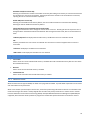
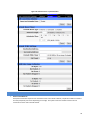
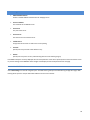
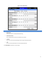
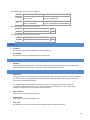
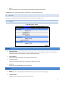
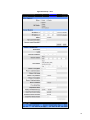
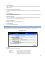
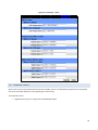
3.3.4 SYSTEM MONITOR
Select Cell Connection from the left navigation pane. The System Monitor tab allows user access to the configuration of
additional self-monitoring for the modem to determine when service provider connections may have been terminated.
48
Figure 30: Cell Connection – System Monitor
Cell Connection Monitor
Reset on Extended Loss
Fixed-point connections expect to have consistent access to the cellular network, compared to mobile connections
that may temporarily lose access depending on coverage. This option causes the modem to reset if the cell
connection is lost for more than 90 seconds.
49
Periodic Reset Timer
Periodic Reset Type
Sets the Periodic Modem Reset timer to an Interval time, a Scheduled day, or disables it.
Interval Length
Sets the Periodic Modem Reset time from 15 to 65,535 minutes. The Periodic Reset is disabled when set to 0.
Default is set to 4320 min. (approximately 3 days)
Scheduled Time
Sets the Periodic Modem Reset to occur at the specified time. Select the days of week desired or 'All' for everyday.
Time is specified as Local Time, based on the location of the modem itself. The modem's current time is shown on
the "home" page.
Periodic Ping Settings
Destination Address
User may enter an accessible IP address or URL that will respond to a ping command.
Secondary Address
User may enter an accessible IP address or URL that will respond to a ping command. This address will be used if
the entered number of consecutive ping failures using the first address is reached.
Periodic Ping Timer
User may enter an interval in increments of 10 seconds. The modem will ping the destination at that interval. Enter
0 to disable this feature.
Fail Count
The modem will reset if the number of consecutive ping failures is equal to or greater than this entry and the
secondary address is being used. Otherwise the modem will switch from the first address to the secondary address
for the ping test.
WAN Data Usage Estimates
This section tracks the data received from and transmitted to the cellular network. This is a tool that may be used to
estimate network usage. These totals are tracked by the router. Your carrier maintains separate statistics from which your
billing is determined. One way to use this tool is to track usage over a fairly short period of typical usage. The total then can
be extrapolated to estimate longer time periods. This router updates these statistics once approximately every 30 seconds.
Press the Clear button to reset the totals to 0.
Rx Bytes:
The total number of bytes received by the modem from the cell network. All statistics will be cleared automatically
if this count exceeds 1 billion (1,000,000,000).
Rx Packets:
The total number of TCP and UDP packets received by the modem from the cell network.
50
Rx Errors:
The number of corrupted TCP and UDP packets received by the modem from the cell network.
Rx Packets Dropped:
The number of TCP and UDP packets received by the modem from the cell network that were not accepted. This
may occur due to memory or throughput problems.
Tx Bytes:
The total number of bytes transmitted by the modem to the cell network. All statistics will be cleared
automatically if this count exceeds 1 billion (1,000,000,000).
Tx Packets:
The total number of TCP and UDP packets transmitted by the modem to the cell network.
Tx Errors:
The number of corrupted TCP and UDP packets received by the modem that were meant to be transmitted on the
cell network.
Tx Packets Dropped:
The number of TCP and UDP packets received by the modem for transmit to the cell network that were not
accepted. This may occur due to memory or throughput problems.
Press the Clear button to reset the totals to 0. These totals are NOT cleared by a modem reboot.
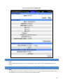
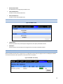
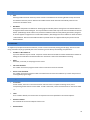
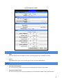
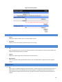
3.3.5 DYNAMIC DNS
Select Cell Connection from the left navigation pane. Select the Dynamic DNS tab to open the Dynamic DNS configuration
page. Dynamic DNS is a system which allows the domain name data of a computer with a varying (dynamic) IP addresses
held in a name server to be updated in real time in order to make it possible to establish connections to that machine
without the need to track the actual IP address themselves at all times. A number of providers offer Dynamic DNS services
("DDNS"), free or for a charge. For example, a free service provided by NO-IP allows users to setup between one and five
host names on a domain name provided by NO-IP. No-IP is the default DNS service.
Figure 31: Cell Connection – Dynamic DNS
51
Dynamic DNS
Dynamic DNS
Selecting Enable will allow the modem to provide the selected service dynamic IP address information. Selecting
Disable will stop any IP information from being sent to the selected service.
Dynamic DNS Address
The internet address to communicate the Dynamic DNS information to. Default is dynupdate.no-ip.com.
Port Number
The port number for the internet address give above. Default is 8245.
User Account
The username used when setting up the account. Used to login to the Dynamic DNS service.
User Password
The password associated with the username account.
Hostname
The hostname identified to the Dynamic DNS service. For example http:/test.myserver.com.
Update Interval
Sets the interval, in minutes (0 to 65,535), the modem will update the Dynamic DNS server of its carrier assigned IP
address. It is recommended to set this interval as long as necessary. Each update is considered a data call by the
cellular provider and could deplete low usage data plan minutes.
The SAVE button must be pressed for changes to take effect.
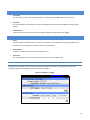
3.4
LAN SETTINGS
Select LAN Settings from the main navigation pane for access to LAN configuration settings and the MAC Filtering tab.
52
Figure 32: LAN – LAN Settings
53
LAN Settings
Ethernet IP Address
This sets the IP address of this device and is the address used to access the configuration pages. If the IP address
changes you will have to re-enter the new IP address in your browser to access the configuration pages. The
default IP is 192.168.1.50 and should be changed for security purposes.
Ethernet Subnet Mask
Sets the subnet mask for the LAN side of the modem to the device
LAN Masquerade
When enabled the Vanguard SC masquerades all Ethernet traffic to the LAN, making all WAN traffic appear as if it
originated from the Vanguard SC. This can be useful in applications where less-capable equipment on the local LAN
cannot cope with connections from multiple Host IP addresses
Bind Services to Eth IP
UDP datagrams or TCP sockets from services inside the Vanguard SC (Serial, IO, GPS) normally appear to come
from the interface (LAN or WAN) closest to the destination. Enable this option to force the source address to be
the LAN Ethernet IP address. This can be useful if packets are being sent through a VPN tunnel. Note that outside
of a tunnel, NAT may still force the source address to be rewritten to the WAN address.
DNS Resolving
DNS Auto
Selecting Enable will allow the servers set as DNS Server 1 or 2 to automatically resolve domain names to IP
addresses. These servers communicate with name servers by sending DNS queries and heeding DNS responses.
Selecting Disable will not allow DNS Sever 1 or 2 to resolve domain names.
DNS Server 1 IP Address
The Ethernet IP address of the preferred DNS server. The default address is 192.168.1.50, the same as the LAN
Ethernet IP Address for the modem. If the LAN Ethernet ID Address changes, the DNS Server 1 address will
automatically change to the same.
DNS Server 2 IP Address
Ethernet address of the alternate DNS server. The default is set to 0.0.0.0.
DHCP Configuration
DHCP
Dynamic Host Configuration Protocol; a protocol used by client devices that are connected to the LAN port of this
device to automatically obtain an IP address assigned by this device. Selecting Enable will configure this device to
assign IP addresses to client devices taken from a pool specified by the values entered in DHCP start range and
DHCP end range. Selecting Disable will turn off this DHCP server functionality
DHCP start range
DHCP server starting IP address. The default is set as 192.168.1.100
54
DHCP end range
DHCP server ending IP address. The maximum usable number is 253
DHCP Lease Time
Sets the duration, in seconds, the connected device is allowed to keep the assigned IP address. In many cases it is
possible for the device to receive the same IP address after the lease time expires.
Remote Administration
Web Server Port
Enter the port number to be used by the web server
Remote Configure
Selecting Enable will allow remote access to the modem’s configuration screens through the cellular network
connection. Selecting Disable will shut off the ability to remotely access the modem’s configuration screens
Incoming Port
Sets the port number used to remotely configure the modem. (Note: Remote Configuration will be unavailable if
the Incoming Port number also appears in an entry in Router | Port Forwarding | IP Mapping Table.)
Admin Password
Sets the password required for remote configuration
Confirm Password
Re-type the Admin Password to confirm the correct spelling
Friendly IP Address
Specifies the IP address from which remote administration is permitted. Entering 0.0.0.0 will allow any IP address.
Leave the fifth box blank (after the /) if specifying a specific IP, or 0.0.0.0. A subnet mask may be entered in the
fifth box. The mask indicates how many bits of the IP address to match. This can be a value from 1 to 32.
Apply Friendly IP Address
Check the box next to a service to allow remote access to the service only from the friendly IP address. Uncheck
this box to allow any IP address access.
SSH, Telnet, and SNMP Ports
Enter the port number that will be used for remote access to the service. Entering zero for the port number will
block remote access to the service. Once a service is blocked (0 entered) or moved to another port, the default
port number (such as 23 for Telnet) can be used in a Port Forwarding rule to provide access to a user device
located behind the modem. Port Forwarding has precedence so if the SSH, Telnet or SNMP port also appears as an
Incoming Port in an entry in Router | Port Forwarding | IP Mapping Table then that service will be unavailable.
55
RADIUS Settings
RADIUS Authentication
Enable or disable RADIUS authentication for webpage access
Server IP Address
The IP address of the RADIUS server
Server Port
The port of the server
Server Secret
Sets the secret to use with the server
Confim Secret
Re-type the Server Secret to confirm the correct spelling
Timeout
Specify how many seconds to wait before a retry
Retries
Specify how many times to retry authenticating with the server before giving up
Press Save to keep the currently displayed value for each parameter. Once Save is pressed, Cancel cannot be used to return
to previous settings. Press Cancel to abort changes and redisplay the last saved parameters for this page.
3.4.1 MAC FILTERING
Select LAN Settings from the left navigation pane. The MAC Filtering tab opens the MAC filtering configuration page. MAC
filtering allows up to five unique device MAC addresses access to the network.
56
Figure 33: LAN – MAC Filtering
MAC Filtering
MAC Filtering
Radio button selection to Enable/Disable MAC filtering
Allowed MAC Address
Enter the MAC address for a device to be allowed on the network.
Comment
Here a name can be inserted describing the device using the allowed MAC address.
Clear
Press to remove the MAC address from the list of allowed addresses.
Press SAVE/CANCEL to implement or cancel changes.
57
3.4.2 IP FILTERING
Figure 34: LAN – IP Filtering
58
The "IP Filtering" page is used to configure IP filters.
The user can enter up to 20 IP filters. Each IP filter is identified by a unique number (from 1 to 20). An IP packet goes
through the filtering logic when IP filtering is enabled and:
1) An IP packet is received on one of the interface and is destined to the Vanguard unit
OR
2) An IP packet is sent by the Vanguard unit
OR
3) An IP packet is forwarded by the Vanguard unit.
The filtering logic is the following:
if exists(filter[1]) AND match(packet, filter[1]) then apply(action[1])
else if exists(filter[2]) AND match(packet, filter[2]) then apply(action[2])
else if exists(filter[3]) AND match(packet, filter[3]) then apply(action[3])
else if exists(filter[20]) AND match(packet, filter[20]) then apply(action[20])
else process packet normally.
Where:
exists(filter[n]) -> The user as defined filter number n.
match(packet, filter[n]) -> The IP packet matches filter number n.
apply(action[n]) -> The action identified in filter number n.
IP Filters
IP FIltering:
Enable : IP filtering is enabled. Any custom IP filters entered by the user will be taken into account when processing
IP packets. The predefined IP filters will also be taken into account.
Disable : IP filtering is disabled.
Add Custom IP Filters
Filter Number:
Each IP filter is identified by a unique number from 1 to 20.
Source IP Address:
Any: Any source IP Address will satisfy this criteria.
Specific :A specific Host IP address.
Range : A range of IP addresses.
If the Exclude field is checked, it means that in order for the packet to match with this criteria, it must NOT have
this source IP address (or NOT be in the given source IP address range).
Destination IP Address:
Any : Any destination IP Address will satisfy this criteria.
Specific :A specific Host IP address.
Range : A range of IP addresses.
If the Exclude field is checked, it means that in order for the packet to match with this criteria, it must NOT have
this destination IP address (or NOT be in the given destination IP address range).
59
Protocol:
Any : Any protocol number.
ICMP : The ICMP protocol (1).
TCP : The TCP protocol (6).
UDP : The UDP protocol (17).
Other : Any other IP protocol.
If the Exclude field is checked, it means that in order for the packet to match with this criteria, it must NOT have
this protocol number.
Source Port:
Any : Any source port number.
Specific : Select a specific source port number.
Range : Select a range of source port number.
If the Exclude field is checked, it means that in order for the packet to match with this criteria, it must NOT have
this source port number (or NOT be in the given source port number range).
Destination Port:
Any : Any destination port number.
Specific : Select a specific destination port number.
Range : Select a range of destination port number.
If the Exclude field is checked, it means that in order for the packet to match with this criteria, it must NOT have
this destination port number (or NOT be in the given destination port number range).
Direction:
The direction corresponds to the path taken by the IP packet inside the Vanguard unit.
An IP packet can TERMINATE inside the Vanguard unit.
WAN to Vanguard:
LAN to Vanguard:
WLAN to Vanguard:
The IP packet is received from the WAN(cellular) interface and is destined to the
Vanguard unit.
The IP packet is received from the LAN interface and is destined to the Vanguard unit.
The IP packet is received from the WiFi interface and is destined to the Vanguard unit.
An IP packet can ORIGINATE from the Vanguard unit.
Vanguard to WAN:
Vanguard to LAN:
Vanguard to WLAN:
The IP packet is sent by the Vanguard unit to the WAN(cellular) interface.
The IP packet is sent by the Vanguard unit to the LAN interface.
The IP packet is sent by the Vanguard unit to the WiFi interface.
An IP packet can be FORWARDED by the Vanguard unit.
WAN to LAN:
WAN to WLAN:
LAN to WAN:
LAN to WLAN:
WLAN to LAN:
The IP packet is received on the WAN(cellular) interface and forwarded to the LAN
interface.
The IP packet is received on the WAN(cellular) interface and forwarded to the WiFi
interface.
The IP packet is received on the LAN interface and forwarded to the WAN(cellular)
interface.
The IP packet is received on the LAN interface and forwarded to the WiFi interface.
The IP packet is received on the WiFi interface and forwarded to the LAN interface.
60
WLAN to WAN:
The IP packet is received on the WiFi interface and forwarded to the WAN(cellular)
interface.
If the Exclude field is checked, it means that in order for the packet to match with this criteria, it must NOT be
processed in the given direction.
Action:
Keep : If IP filtering is enabled and an IP packet matches all criteria in the IP filter, keep the IP packet (continue
normal processing of the IP packet).
Drop : If IP filtering is enabled and an IP packet matches all criteria in the IP filter, drop the IP packet.
Custom IP Filters
Del:
Click on Del to delete the filter.
3.5
WLAN SETTINGS
The WLAN interface of the Vanguard Cellular Broadband Router can be configured to operate in Client mode or in Access
Point mode.
The AUX LED displays the status of the WLAN interface:
Off
The WLAN interface is not installed.
Red
The WLAN interface is not disabled.
Amber
The WLAN interface is configured for Client mode and is searching for an Access Point.
Green
The WLAN interface is not configured for Client mode and is connected to an Access Point, or is configured
for Access Point mode and is ready to accept connections.
Flashing
Green
There is data traffic on the WLAN channel.
3.5.1 MAIN
Figure 35: WLAN – Main
61
Configuration
Wireless Mode:
Disable
The WLAN interface is disabled.
Client
The WLAN interface operates in Client mode. Parameters can be set on the Client tab.
Access
Point
The WLAN interface operates in Access Point mode. Parameters can be set on the Access
Point tab.
Status
IP Address:
IP Address assigned to the WLAN interface.
Subnet Mask:
Subnet mask assigned to the WLAN interface.
SSID:
Name of the wireless local area network.
Authentication:
Authentication method currently used.
Encryption:
Encryption method currently used.
Channel:
Channel currently in use.
State:
Current state of the WLAN interface. In Access Point mode, indicates how many clients are connected.
RSSI:
Received Signal Strength indicator.
3.5.2 CLIENT
The user can configure up to 20 Access Points. The Vanguard Cellular Broadband Router will try to connect to the best
Access Point in the list that is reachable. When the Vanguard unit connects to an Access Point, it starts a DHCP client on the
interface. The Access Point must provide a DHCP server. The DHCP server must provide an IP address, netmask and gateway
to the Vanguard unit. When the Vanguard unit is connected to an Access Point, the default route is set to point to the
gateway address obtained from the DHCP server.
Note: The Access Point must broadcast the SSID in order for the Client to be able to connect to it.
62
Figure 36: WLAN – Client
The following table shows the list of available authentications method with their associated
encryption methods.
Authentication Encryption
1) Open
none, WEP
2) Shared
WEP
3) WPAnone
TKIP, AES
4) WPA-PSK
TKIP, AES
5) WPA2-PSK
AES
The following table shows how to set a WEP key.
WEP key
64-bit
128-bit
ASCII (Text)
5 character string (alphanumeric) 13 character string (alphanumeric)
Example: Hello
Example: LongHello1234
Hex
10 Hexadecimal digits
Example: 1A2B3C4D5E
26 Hexadecimal digits
Example: 1A2B3C4D5E6F7788990A0B0C0D
The following table shows how to set a TKIP key.
TKIP key
Description
Example
ASCII (Text) A string of 8 to 63 character (alphanumeric) Hello123
The following table shows how to set an AES key.
AES key
Description
Example
ASCII (Text) A string of 8 to 63 character (alphanumeric) Hello123
63
3.5.3 ACCESS POINT
Figure 37: WLAN – Access Point
Wireless Settings
Wireless Parameters for Access Point mode.
The following table shows the list of available authentication methods with their associated
encryption methods.
Authentication Encryption
1) Open
none, WEP
2) Shared
WEP
3) WPAnone
TKIP, AES
64
The following table shows how to set a WEP key.
WEP key
64-bit
128-bit
ASCII (Text)
5 character string (alphanumeric) 13 character string (alphanumeric)
Example: Hello
Example: LongHello1234
Hex
10 Hexadecimal digits
Example: 1A2B3C4D5E
26 Hexadecimal digits
Example: 1A2B3C4D5E6F7788990A0B0C0D
The following table shows how to set a TKIP key.
TKIP key
Description
Example
ASCII (Text) A string of 8 to 63 character (alphanumeric) Hello123
The following table shows how to set an AES key.
AES key
Description
Example
ASCII (Text) A string of 8 to 63 character (alphanumeric) Hello123
IP Settings
IP Address:
This sets the IP address for the WLAN side of the Vanguard unit.
Subnet Mask:
Sets the subnet mask for the WLAN side of the Vanguard unit.
DNS Masquerade
DNS Auto:
Selecting Enable will automatically set the preferred DNS Server to the WLAN IP address of the Vanguard unit.
Selecting Disable will allow the user to select the preferred and alternate DNS servers.
DHCP Server Configuration
DHCP Server:
Selecting "Enable" will configure this device to assign IP addresses to client devices taken from a pool specified by
the values entered in "Start IP Address" and "End IP Address". Selecting "Disable" will turn off the DHCP server
functionality for the Ethernet interface.
The Vanguard helps to protect against addressing conflict by preventing the operator from saving the
configuration when the DHCP lease range conflicts with the interface IP address. If such a conflict exists, a
messages is displayed after the user pressed the "Save" button.
Start IP Address:
DHCP server's IP address pool starting value.
End IP Address:
DHCP server's IP address pool ending value.
Lease Time:
Sets the duration, in seconds, that the client is allowed to keep the assigned IP address.
65
Domain Name Suffix:
The DNS suffix to be assigned by the DHCP server.
Preferred DNS Server:
IP address of the preferred DNS server.
Alternate DNS Server:
IP address of the alternate DNS server.
3.5.4 STATS
Figure 38: WLAN – Stats
TX/RX Packets:
Amount of packets sent (received) by the Vanguard unit over (from) the WLAN interface.
X/RX Bytes:
Amount of bytes sent (received) by the Vanguard unit over (from) the WLAN interface.
3.5.5 SITE SURVEY
When the WLAN interface of the Vanguard unit is configured for Client mode, this page scans for and displays the WLAN
Access Points detected. (This operation can take some time to complete.)
Figure 39: WLAN – Site Survey
66
3.6
ROUTER
Select Router from the left navigation pane for user access to Port Forwarding and Static Routing tabs.
3.6.1 PORT FORWARDING
Port Forwarding is a technique for transmitting and receiving network traffic through a router that involves re-writing the
source and/or destination IP addresses and usually the TCP/UDP port numbers of IP packets as they pass through. The
various routing configurations will be displayed in the IP mapping table at the bottom of the screen.
Figure 40: Router – Port Forwarding
DMZ Support
DMZ is a host on the internal network that has all ports exposed, except those ports forwarded otherwise.
DMZ
Radio button selection to Enable/Disable; Select Enable to allow the modem to use DMZ routes using the address
set in the Destination IP Address. Select Disable to shut down the DMZ functionality.
67
Friendly IP Address
Optionally restricts DMZ access to only the specified IP address. If set to "0.0.0.0", the DMZ is open to all incoming
IP Addresses.
Destination IP Address
The IP address which has all ports exposed, except ports defined in the Port Forwarding configuration.
The SAVE button must be pressed for changes to take effect.
Port Forwarding Support
Port Forwarding
Radio button selection to Enable/Disable. Select Enable to allow the modem to use the Port Forwarding routes
described in the IP mapping table. Select Disable to shut down the Port Forwarding functionality.
The SAVE button must be pressed for changes to take effect.
Port Forwarding Configuration
Map Name
Sets the Map Name for the IP mapping table at the bottom of the screen. The Map Name can be up to ten
characters in length. Do not use spaces in the character string
Protocol
Sets the data protocol as either tcp, udp, or all
Friendly IP Address
Specifies an IP address that is allowed to access the modem or a wildcard IP address of 0.0.0.0 that allows all IP
addresses to access the modem. Leave the fifth box blank (after the /) if specifying a specific IP, or 0.0.0.0. A
subnet mask may be entered in the fifth box. The mask indicates how many bits of the IP address to match. This
can be a value from 1 to 32.
Inbound Port
Sets the external port number for incoming requests. (Note: Port Forwarding rules take precedence over the
services specified in LAN Settings | Remote Administration | Incoming port, SSH Port, Telnet Port or SNMP Port.)
Destination IP Address
Sets the Local Area Network Address of the device connected to the modem's Ethernet jack. Inbound requests will
be forwarded to this IP address.
Destination Port
Sets the Local Area Network port number used when forwarding to the destination IP address.
Once you have completed the entry of the above fields, press the ADD button to save the new entry.
68
3.6.2 STATIC ROUTES
Select the Static Routes tab to open the routing configuration page. Static route tables may be created from the Routing
screen and appear at the bottom. Static Routing refers to a manual method used to set up routing between networks.
Figure 41: Router – Static Routes
Static Routes
Route Name
Sets the alphanumeric identifier of the static route in the Static Route Table.
Destination IP Address
Sets the IP address of the destination network.
IP Subnet Mask
Sets the subnet mask of the destination network.
Gateway
Sets ppp (this router's wireless internet connection), pptp (VPN), GRE Tunnel, or the local network IP address for
the gateway to the destination network.
Gateway IP Address
This is only used if local IP addr was selected for gateway. Enter the address of the local gateway.
69
Metric
Enter a number from 1 to 20. The lower the metric value the higher the route priority.
The ADD button must be pressed to add the configured route to the Static Route Table.
3.7
SECURITY
From the main navigation panel, select Security for access to PPTP, IPsec and GRE screens.
3.7.1 STATUS
Figure 42: Security – Status
PPTP Client
PPTP Client Status:
Indicates the status of the PPTP Client interface, usually UP when connected properly. PPTP is the Point-to-Point
Tunneling Protocol used to implement a Virtual Private Network (VPN)
PPTP IP Address:
The current IP address assigned to the modem by the VPN server.
PPTP Subnet Mask:
Usually set to 255.255.255.255, but may be different depending on VPN.
PPTP P-t-P:
The PPTP P-t-P is the LAN address of your VPN server.
PPTP Client
Status:
The PPTP Server is either ENABLED or DISABLED based on user's selection on Security page.
Connected Users:
Number of users currently connected to the PPTP Server.
70
IPsec Tunnels
Status:
The number of established IPsec tunnels based on the number of tunnels Enabled on the Security | IPsec page.
3.7.2 PPTP
The Point-to-Point Tunneling Protocol (PPTP) is a method for implementing virtual private networks (VPN).
Figure 43: Security – PPTP
PPTP Client Configuration
PPTP Client
Selecting Enable will allow the PPTP functionality. Selecting Disable will shut off PPTP functionality.
Set Default Route to PPTP
Selecting Enable will route all IP traffic through the PPTP network. Selecting Disable will route only PPTP traffic
through the PPTP network.
71
PPTP Server
The IP address of the virtual private network server on which to connect.
Username
The username required by the VPN server.
Password
The password, associated with the username, required by the VPN server.
PPTP Server Configuration
PPTP Server
Selecting Enable starts the VPN server, and selecting Disable stops it.
Server Local IP
The IP address that clients will use to communicate with the server after they connect.
Client IP Range
The pool of IP addresses assigned to clients.
Protocols Allowed
Selecting a protocol will instruct the VPN server to accept clients who use that protocol. The server will reject
clients using any of the un-selected protocols.
Encryption
Selecting 'Use MPPE' will enable Microsoft Point-to-Point Encryption for communication between the server and
clients. This option requires the MS-CHAP or MS-CHAPv2 protocol.
PPTP Server User Configuration
Full Name
This name can be used as a more descriptive name for a client. It is not used by the server. No spaces are allowed
in the name.
Username
The name used by a client to log in to the server.
Password
The password, with associated username, used by a client to log in to the server.
3.7.3 IPSEC
IPsec serves to configure secured communication tunnels. The various tunnel configurations will be displayed in the Tunnel
Table at the bottom of the page. All tunnels are created using the ESP (Encapsulating Security Payload) protocol.
72
Figure 44: Security – IPsec
73
IPsec Support
IPsec
Selecting Enable will launch the IPsec process and start all enabled tunnels. Selecting Disable will stop all tunnels
and shutdown the IPsec process. Note that all enabled tunnels will be launched automatically when the unit
connects to the cellular carrier.
NAT Mode
Determines how packets are addressed. Selecting Bypass will allow packets coming from Local Subnet addresses
through the NAT firewall unchanged. This may be sufficient when traffic only travels from Local Subnet to Remote
Subnet. (LAN Settings > Bind to Eth IP may need to be enabled to make sure that packets generated by Vanguard
SC services appear to originate from a Local Subnet address.) NAT changes the source address to match the Status
> PPP IP Address. NAT-Traversal enables the NAT-T protocol which can support traffic beyond just the Local &
Remote Subnets.
Tunnel Monitor
To supplement/complement Dead Peer Detection, tunnels can be monitored by sending periodic pings, with the tunnels
being restarted if the pings repeatedly fail. Tunnel monitoring is controlled by the following five parameters …
IP Address 1 & IP Address 2:
Up to two addresses may be entered. Only those tunnels where the IP address matches the Remote IP Address or
belongs to the Local Subnet or Remote Subnet are monitored. A value of 0.0.0.0 disables monitoring.
Delay:
How often, in seconds, to send pings over the tunnel.
Fail count threshold:
The number of successive pings that need to fail to cause the tunnel to be restarted.
Success count threshold:
The number of successive pings that need to succeed for the tunnel to be considered “up” and for the process of
counting failed pings to begin.
Tunnel Configuration
Tunnel Item
Tunnel number, starts from 1 and increments for each new tunnel. To update an existing tunnel, use its
corresponding number from the tunnel table. To add a new tunnel, use the last tunnel shown in the Tunnel Table
+ 1.
Label
This is a label to identify a tunnel and must correspond to the name specified for the remote endpoint.
Remote IP Address
The IP address of the remote endpoint of the tunnel.
Remote Subnet
74
Choose None if encrypted packets are only destined for the Remote IP Address. Use an IP address / mask if
encrypted packets are also destined for the specified network that is beyond the Remote IP Address. IMPORTANT:
The Remote Subnet and Local Subnet addresses must not overlap!
Local Subnet
Choose None if only packets generated by Vanguard SC services will be sent over the tunnel. Choose Ethernet if
packets from the local LAN will also be sent over the tunnel. (LAN Settings > Bind to Eth IP may need to be enabled
to make sure that packets generated by Vanguard SC services appear to originate from a Local Subnet address.)
Use an IP address / mask if a network beyond the local LAN will be sending packets over the tunnel. IMPORTANT:
The Remote Subnet and Local Subnet addresses must not overlap!
Phase 1 Encryption
Use AES-128, AES-256 or 3DES encryption.
Phase 1 Authentication
Use MD5 or SHA1 hashing.
Phase 1 DH Group
Negotiate (Auto) or use 768 (Group 1), 1024 (Group 2), 1536 (Group 5) or 2048 (Group 14) bit keys.
Phase 1 Key Lifetime
How long the keying channel of a connection should last before being renegotiated.
Phase 2 Encryption
Use AES-128, AES-256 or 3DES encryption.
Phase 2 Authentication
Use MD5 or SHA1 hashing.
Phase 2 Lifetime
How long a particular instance of a connection should last, from successful negotiation to expiry.
Pre-shared Key:
Predetermined key known to both the local unit and the remote side prior to establishing the tunnel.
Negotiation Mode
Choose Normal to allow IPsec to negotiate some connection parameters. Choose Aggressive to require that only
those parameters selected above can be used to create the tunnel.
Perfect Forward Secrecy
Enable Perfect Forward Secrecy for the session keys.
Dead Peer Detection Delay
Tunnel keepalive time for R_U_THERE packets during idle periods.
75
Dead Peer Detection Timeout
Timeout time during tunnel idle periods where no R_U_THERE_ACK has been received.
Dead Peer Detection Action
Action to be taken when timeout value is reached.
Once you have completed the entry of the above fields, press the ADD/UPDATE button to save the new entry.
Tunnel Table
Enable
Check Ena to enable a tunnel. The tunnel’s state is saved across resets
View
Click on View to open a page showing the log of the tunnel’s negotiation activity
Delete
Click on Del to delete the tunnel
3.7.4 GRE
The GRE page is used to add and delete GRE (Generic Route Encapsulation) tunnels. Current tunnels are listed below. Up to
two networks that lie beyond the tunnel may be specified and routes to those networks are automatically created when the
tunnel is established. Static local and remote IP addresses are necessary to allow for the tunnel automatic (re)connection.
Figure 45: Security – GRE
76
GRE Tunnel Configuration
Local IP Address:
The local (normally WAN interface) IP address associated with the tunnel.
Remote IP Address:
The remote IP address associated with the tunnel.
Tunnel IP Address:
The IP address assigned to the tunnel interface.
[ Example: 192.168.10.100 ]
Tunnel Subnet & Mask:
The tunnel subnet and mask that must include the above Tunnel IP Address.
[ Example: 192.168.10.0/24 ]
Remote User Subnet 1 & Mask:
The IP network representing that of the remote user subnet, accessible via the tunnel.
[ Example: 192.168.20.0/24 ]
Remote User Subnet 2 & Mask:
A possible second IP network representing another remote user subnet.
[ Example: 192.168.15.0/24 ]
NOTE:
All subnets must differ from one another.
If more than two remote user subnets are necessary, additional routes can be setup manually via the Router |
Static Routes web page using the Tunnel IP Address as the gateway.
3.8
SERIAL
From the main navigation pane, select Serial for access to both external and internal serial port configuration screens.
3.8.1 EXTERNAL SERIAL
The External Serial screen is used to configure the RS-232 Serial Port parameters and Packet Assembler and Disassembler
(PAD) functionality. The PAD feature forwards requests that come in on a specific port to the Serial connector.
77
Figure 46: Serial – External Serial
78
Serial Port Settings
Serial Port:
When disabled, the external serial port is left free for use by an ODP application.
GPS Configuration
Select GPS to enable GPS reports through the serial port. Note that the report format is set on the GPS | Settings page. Set
the appropriate TCP Server Format in the Local and/or Remote Delivery sections.
Report Trigger:
On Loss of Cellular Signal: Select this if the GPS reports are output only when the cellular signal is lost. Note that
there can be a delay of around 30 seconds before the serial reports appear on the serial port after the cellular
signal is lost.
Always: GPS reports are always sent out the serial port.
Reports:
Local (1/sec): Select this to have the Local report sent out the serial port each second.
Remote (AAVL): Select this to have the Remote report sent out the serial port. The report rate is based on the
AAVL settings.
Baud Rate:
Select the serial port baud rate. The character format is fixed at 8 data bits, No parity, 1 stop bit.
External Serial Port Configuration
Show Version on Boot
When enabled, the router model number and firmware version are transmitted out the serial port at router boot.
Additionally, "OK" is transmitted when router is ready to receive data and when PPP connection is made. When
disabled, these indicators will not be transmitted out the serial port.
Baud Rate
Sets the baud rate of the serial port. Settings may range from 300 to 115,200 bits per second. The default baud
rate is 115,200 bps.
Inter Character Timeout
Sets the Inter Character Timeout from 1 to 65,535 ms.
DTR
Defines the Data Terminal Ready behavior. Refer to table below for DTR descriptions.
79
Table 8 – DTR Descriptions
AT&D0
Ignore DTR.
AT&D1
If in the Online Data State, upon an on-to-off transition of DTR, the modem enters Online Command
State and issues an OK result code; the call remains connected. Otherwise, ignore DTR.
AT&D2
If in the Online Data State or Online Command State upon an on-to-off transition of DTR, the modem
performs an orderly clear-down of the call and returns to the command state. Automatic answer is
disabled while DTR remains off.
The modem auto-dials the default remote station upon an off-to-on transition of DTR and enters the
Online Data State. The modem ends the call and enters the command state upon an on- to-off
transition of DTR.
The modem auto-dials the default remote station upon an on-to-off transition of DTR and enters the
Online Data State. The modem ends the call and enters the command state upon an off-to-on transition
of DTR.
Upon an on-to-off transition of DTR, the modem performs an orderly clear-down of any session and
turns OFF the RF module. Upon an off-to-on transition of DTR, the modem turns ON the RF module and
reestablishes the radio session.
Upon an on-to-off transition of DTR, the modem performs an orderly clear-down of any session and
turns OFF the RF module. Upon an off-to-on transition of DTR, the modem turns ON the RF module and
reestablishes the radio session.
The modem auto-dials the default remote station upon determining DTR is OFF and enters the Online
Data State. The modem ends the call and enters the command state upon determining DTR is ON.
AT&D4
AT&D5
AT&D6
AT&D7
AT&D8
AT&D9
The modem auto-dials the default remote station upon determining DTR is ON and enters the Online
Data State. The modem ends the call and enters the command state upon determining DTR is OFF.
Flow Control
Sets the Flow Control to None or Hardware control
DSR
Sets the Data Set Ready to Always On, On When Available, On When Connected or Always Off. The DSR parameter
determines how the modem controls the state of the Data Set Ready circuit. The default value is Always Off.
― Always On: DSR is always on.
― On When Available: DSR is on when the RF signal present and phone registered on network.
― On When Connected: DSR is on when connected to CDMA.
― Always Off: DSR is always off.
DCD
The DCD parameter determines how the modem controls the state of the Carrier Detect circuit and the amber DCD
LED on the front panel. The default value is Connect On.
― Always On: DCD is always on.
― Connect On: DCD is on when connected to a remote host.
― Always Off: DCD is always off.
RI
The RI parameter determines how the modem controls the state of the Ring Indicator circuit. The default value is
Always Off.
80
― Always On: RI is always on.
― Connect On: RI tracks incoming ring pulse.
― Always Off: RI is always off.
External PAD Settings
PAD Mode
Select button to set the PAD mode of the modem as a Server or Client. In Client mode, the modem will initiate an
outbound connection to the Remote Host IP Address with the Outgoing Port based on the selected DTR setting. In
Server mode, the modem will accept one incoming connection on the specified Incoming Port. The modem will
not accept multiple incoming connections at the same time – additional connections are arbitrated based on the
Server Session Closed On and Timeout parameters. Note: It is possible to override Server mode and make an
outgoing client connection using the RS-232 command set.
atd*xxx.xxx.xxx.xxx:yyyyy – When in server mode, and no connection is active, the atd* command (followed by an
IP address) can be issued to initiate an outbound client connection to the specified IP address and port as specified
after the colon. If no port is specified, the port number used is the Outgoing Port parameter. To hang-up such a
connection, 3 ‘+’ characters must be inserted into the outgoing stream (“+++”). The modem will return to
command mode once it has seen the “+++” and respond with OK. The connection can then be broken by entering
“ath”. The modem will return to server mode. Such a client connection can be repeated again as necessary, as
long as each connection is hung-up before a new one is made.
Additional note: The modem is capable of only 1 PAD connection at a time. When a manual client connection is in
progress (atd*xxx.xxx.xxx.xxx), a connection attempt by an incoming client may result in the disabling of the PAD
function until the next device reset.
Pad Protocol
Sets the data protocol of the PAD to tcp or udp data. If you have set PAD Mode as server you can choose either to
support either type of client.
Incoming Friendly IP Address
Sets the IP address of the device using the PAD functionality
Server Session Closed On
This is only available if PAD mode is Server. This option selects under which condition the server will terminate an
established connection.
New Client: If a different client attempts to connect, it will be successful and the current client will be forcibly
disconnected, without any warning. Otherwise, the current client remains connected indefinitely.
Timeout: A new client will be accepted only after a specified timeout. The duration of the timeout is specified by
the Inactivity timeout, or the Hard timeout, or a combination of both.
The default value is New Client.
Server Inactivity Timeout
Time after which the current connection with Client will be terminated without warning. This time starts over
again each time the Client sends data to the server. This parameter is ignored if the session closes on New Client. If
81
PAD protocol is tcp, the timeout is specified in minutes. If UDP, the timeout is specified in seconds. The valid range
for either is 1-65535. 0 will disable this timer.
If both Inactivity Timeout and Hard Timeout are enabled, (neither is 0), then a client session will be terminated
when either timeout is met. In this case, the value for Hard Timeout must exceed the value for Inactivity Timeout.
If the Inactivity Timeout is met, the client will be terminated. If the Hard Timeout is exceeded without meeting the
Inactivity Timeout, the client will be terminated by the Hard Timeout.
Server Hard Timeout
Time after which the current connection with Client will be terminated without warning. This is a fixed time from
the initial connection, no matter how much or how often the Client sends data to the server. This parameter is
ignored if the session closes on New Client. If PAD protocol is tcp, the timeout is specified in minutes. If udp, the
timeout is specified in seconds. The valid range for either is 1-65535. 0 will disable this timer.
If both Inactivity Timeout and Hard Timeout are enabled, (neither is 0), then a client session will be terminated
when either timeout is met. In this case, the value for Hard Timeout must exceed the value for Inactivity Timeout.
If the Inactivity Timeout is met, the client will be terminated. If the Hard Timeout is exceeded without meeting the
Inactivity Timeout, the client will be terminated by the Hard Timeout.
Incoming Port
Sets the port number used to forward incoming requests to the serial port
Outgoing Port
Sets the port number used to send outgoing requests from the serial port
Remote Host IP Address
Sets the Server IP address to connect with when using the PAD in client mode
TCP Client Keep Alive
When in client mode and enabled, TCP Keep Alive packets will be sent from the client to the server periodically in
order to detect a broken connection. The modem will automatically try to re-establish the connection if necessary.
Changing this setting will affect the use of TCP Keep Alive on the next client session. It will not affect an existing
session
TCP Client Keep Alive Time
Time in seconds between keep alive cycles. A keep alive cycle will consist of one or more keep alive probes
separated by the keep alive interval.
TCP Client Keep Alive Probes
Number of keep alive packets that must fail before connection is considered closed
TCP Client Keep Alive Intvl
Time in seconds after which a keep alive packet is considered to be failed (if not acknowledged). Another packet is
sent at this time if TCP Client Keep Alive Probes limit has not been reached
82
PAD Log
When enabled, as data passes through the PAD, a copy is stored in a log file located on the modem at
/tmp/padlog. The log will stop saving data when full and data is lost at modem reset.
3.8.2 INTERNAL SERIAL
The Internal Serial screen is used to configure the internal RS232 Serial Port parameters and Packet Assembler and
Disassembler (PAD) functionality. The PAD feature forwards requests that come in on a specific port to the internal serial
port.
Figure 47: Serial – Internal Serial
Serial Port Configuration
Baud Rate
Sets the baud rate of the serial port. Settings may range from 300 to 115,200 bits per second. The default baud
rate is 115,200 bps.
PAD Settings
Remote IP Address
Sets the IP address of the device using the PAD functionality
Remote Port
Sets the port number used by the remote device to accept requests from the Vanguard SC
Local Port
Sets the port number used by the Vanguard SC to accept requests from the remote device
83
3.9
PAD Mode
Select buttons to set the PAD mode of the Vanguard SC as a Server or Client
Pad Protocol
Sets the data protocol of the PAD to tcp or udp data
TCP Client Keep Alive
When in client mode and enabled, TCP Keep Alive packets will be sent from the client to the server periodically in
order to detect a broken connection. The modem will automatically try to re-establish the connection if necessary.
Changing this setting will affect the use of TCP Keep Alive on the next client session. It will not affect an existing
session. When this option is enabled, the timing and number of Keep Alive attempts is controlled by parameters
defined on the External Serial page. It is not possible to have different timing settings for each serial port
PAD Log
If enabled, a log of the data passed through the modem is saved at /tmp/intpadlog. The log will stop saving data
when full and data is lost at modem reset.
GPS
The Vanguard Cellular Broadband Router contains a standalone, high-accuracy, high-report-rate (12 satellites with WAAS
and Differential Correction, 1 report per second) GPS receiver.
The GPS LED on the front panel provides the status of the receiver:
GPS LED
Off
Amber
Green
Red
Flashing Red
MEANING
No GPS installed or Cell-modem GPS disabled
Acquiring GPS position
Valid positions being reported
Position lost, reporting Last Known Position
Position lost for more than 2 minutes
3.9.1 AAVL
The "Autonomous Automatic Vehicle Location" (AAVL) feature adds the ability for GPS-equipped Vanguard Cellular
Broadband Routers to transmit position reports either to a host connected to the local Ethernet port or to a remote host
over the cellular network. AAVL allows the system designer to specify the maximum distance or the time interval between
remote position reports.
Position reports can be transmitted in a number of possible formats. When the format is disabled or the Address or Port
fields are blank, no report is sent.
84
FORMAT
TAIP, No
ID
TAIP,
With ID
NMEA,
GGA
NMEA,
GLL
NMEA,
RMC
NMEA,
VTG
DEFINITION
Trimble ASCII
Interface
Protocol (TAIP),
No ID
Trimble ASCII
Interface
Protocol (TAIP),
With ID
NMEA GGA
(Global
Positioning
System Fix
Data)
NMEA GLL
(Geographic
Latitude &
Longitude)
NMEA RMC
(Recommended
Minimum data)
NMEA VTG
(Vector Track
and speed over
Ground)
EXAMPLE
>RPV73511+4549542-0736643100035822;*7F<
>RPV56655+4549542-0736643300000002;ID=ADAM12;*5E<
$GPGGA,202742.0,4529.7240,N,7339.8585,W,2,9,0.9,28,M,,,,*3E
$GPGLL,4529.7241,N,7339.8584,W,202645.0,A,D*7C
$GPRMC,153716.00,A,4529.72428,N,07339.86082,W,0.007,,180108,,,A*69
$GPVTG,,T,,M,0.004,N,0.008,K,A*2F
GPS "sentences" are collected the from embedded GPS receiver in the Vanguard Cellular Broadband Router. These
sentences are converted into the above formats and are provided to both local and remote delivery services. Two TCP ports
are available for clients to connect to and receive reports at the local or remote reporting rate. Each report from the TCP
ports is terminated with carriage-return/linefeed characters (CRLF). Up to two local UDP Hosts and three remote UDP Hosts
may be specified. Reports are sent as a datagram with no terminating CRLF.
85
Figure 48: GPS – Settings
86
3.9.2 SETTINGS
GPS Settings
Differential Correction:
Differention Correction allows WAAS correction information to be used to improve accuracy of the GPS position
reports.
NOTE: WAAS correction applies to North America only. The WAAS satellites currently in service are 48 (Galaxy 15)
and 51 (Anik F1R). The previous WAAS satellites 35 and 47 were taken out of service on 2007/07/30.
Report Rate:
For applications that require it, GPS reports, normally received from the internal GPS receiver once per second, can
be received at a rate of 4 per second. Local Delivery reports are sent at this rate. Remote Delivery reports are still
limited by the “But no less than X seconds between reports” setting.
Autonomous Automatic Vehicle Location (AAVL) Settings
TAIP Vehicle ID:
The TAIP, With ID format allows a report to contain a user-supplied field to identify the sending mobile. This readonly field, which may contain up to 8 letters or digits (special characters not allowed), is taken from the Unit ID
that can be set from Unit Status | Basic Settings | Unit ID | ID.
Local Delivery
The Vanguard Cellular Broadband Router will produce a report each second and send it to any connected TCP clients and to
the specified UDP hosts. IMPORTANT! Local reports should only be delivered to addresses reachable through the local LAN
or WLAN ports. Sending reports once per second or faster over the cellular network could result in a congested cellular
network and/or extremely large network usage charges.
TCP Server Format:
Reports in the specified format (see the table above) are available to local clients that connect to TCP port 6257 of
the Vanguard Cellular Broadband Router.
UDP Host (1,2) Format:
Reports in the specified format (see the table above) are sent to the specified IP address & port. NOTE: Different
reports can be directed to the same UDP Host address & port.
UDP Host (1,2) Address:
IP address of the UDP Host in dotted decimal format.
UDP Host (1,2) Port:
IP Port of the UDP Host (1024-65535).
Remote Delivery
The Vanguard Cellular Broadband Router can be configured to report after a certain time or distance.
Report every () seconds:
Trigger the sending of a new remote report if the time since the last remote report exceeds the specified number
of seconds.
87
Report every () meters:
Trigger the sending of a new remote report if the distance since the last remote report exceeds the specified
distance (in meters).
But no less than () seconds between reports:
To prevent a fast-moving vehicle from reporting too frequently, a lower limit on the time between reports can be
specified.
TCP Server Format:
Reports in the specified format (see the table above) are available to remote clients that connect to TCP port 6258
of the Vanguard Cellular Broadband Router.
UDP Host (1,2,3) Format:
Reports in the specified format (see the table above) are sent to the specified IP address & port. NOTE: Different
reports can be directed to the same UDP Host address & port.
UDP Host (1,2,3) Address:
IP address of the UDP Host in dotted decimal format.
UDP Host (1,2,3) Port:
IP Port of the UDP Host (1024-65535).
3.9.3 STATUS
This section displays the current status of the GPS receiver. Click on the “Refresh” button to update the display.
Figure 49: GPS – Status
Condition:
Indicates the quality of received GPS reports.
Not Installed
Disabled
No Fix / Invalid
This unit does not have a GPS receiver installed.
The cell-module GPS receiver has be disabled.
The GPS receiver has not yet acquired enough
satellites to provide an accurate position, or the
88
Standard GPS Fix
Differential GPS Fix
Estimated / Last
Known Position
previous Estimated Position is over 3 minutes
old.
GPS position is reported using no additional
correction information.
Differential GPS corrects various inaccuracies in
the GPS system to yield measurements accurate
to a couple of meters when the mobile is
moving and even better when stationary.
Satellite reception has degraded to the point
where only an Estimated position or the Last
Known Position can be reported.
Number of Satellites:
Indicates the number of satellite signals being received and used to calculate position.
UTC:
The current time according to Universal Coordinated Time in hh:mm:ss, using a 24-hour clock format.
Position:
The current position in Latitude (North-South) and Longitude (East-West). Positions are reported in degrees and
decimal minutes. For example, a Longitude of 73 degrees, 39 minutes and 45 seconds West appears as: 73deg
39.75000min W.
Altitude:
The current height above Mean Sea Level in meters.
True Course:
Shows the current GPS-generated true course in degrees.
Ground Speed:
Shows travel speed (in Km/h).
3.10 DIAGNOSTICS
From the main navigation pane, select Diagnostics for access to the SNMP and Logging screens.
3.10.1 SNMP
The Simple Network Management Protocol (SNMP) is used in network management systems to monitor network-attached
devices for conditions that warrant administrative attention. SNMP version v2c and v3 are supported with the exception of
INFORM.
89
Figure 50: Diagnostics – SNMP
SNMP Configuration
SNMP
Selecting Enable will allow the SNMP functionality. Selecting Disable will shut off SNMP functionality.
Version
With SNMP Enabled, select the corresponding version that matches the SNMP Manager.
SNMP v2c
Read-only Community Name
The community string used for accessing the read-only Management Information Bases (MIBs)
Read-write Community Name
The community string used for accessing all Management Information Bases (MIBs) including writable objects
90
SNMP v3
User Name
The user name for secure access to the Management Information Bases (MIBs) observing v3 standard
Password
The corresponding user password for accessing the Management Information Bases (MIBs) including writable
objects
Authentication
Selecting the authentication method for accessing the Management Information Bases (MIBs)
Traps
Traps
Selecting Enable will allow the active trap events to be reported to the defined server(s). Selecting Disable will
desactivate events reporting. Up to four destinations can be specified.
Server Address
IP address of server to which the trap events will be sent to.
Server Port
The corresponding server port to which the trap events will be sent to (default 162).
3.10.2 LOGGING
The Logging screen provides a way to capture the current status log of the modem. Log information is useful when
contacting CalAmp Technical Support to resolve operational problems.
Figure 51: Diagnosics – Logging
91
Current Firmware Information
Version
Displays the modem firmware version currently loaded in the unit
Kernel Date
Displays the date of the operating system kernel the unit is running
Logging Settings
Auto-Logging
Selecting Enable and pressing Save will enable the logging capability which saves periodic and event driven logs to
permanent memory. Technical Services personnel may find such logs useful in analyzing field issues. Selecting
Disable and pressing Save will disable the logging capability. This is the default setting. To make best use of
available memory it is recommended to only enable the logging capability if it is necessary to help diagnose an
issue.
Log File Actions
Log Action
― Store in modem: Selecting Store in Modem and pressing Go will create a current status log, and overwrite any
previously saved log. This action will save a log even if auto-logging is disabled. It is best to save the log
immediately following the adverse event, and before any reboot. This log will contain only information
collected since the most recent reboot of the device.
― Display: Selecting Display and pressing Go will display a previously stored log directly to the web browser. You
can use your mouse to select the text, copy it, and paste it into a text editor to save the log on your computer.
― TFTP to Server: Selecting TFTP to Server and pressing Go will initiate a transfer of a previously saved log file to
a specified IP address using the TFTP protocol. In order for the transfer to be successful, a reachable IP address
must be entered under TFTP Server IP and the computer at that IP address must be running a TFTP Server
program. Many free TFTP Servers are available for download over the internet. Note that TFTP is different
than FTP.
TFTP Server IP
When selecting TFTP to Server and pressing Go a valid and reachable IP address must be entered here in order to
complete the transfer of the saved log file using the TFTP protocol. In order for the transfer to be successful, a
reachable IP address must be entered under TFTP Server IP and the computer at that IP address must be running a
TFTP Server program. Many free TFTP Servers are available for download over the internet. Note that TFTP is
different than FTP.
92
3.11 I/O SETTINGS
3.11.1 STATUS
Figure 52: I/O Settings – Status
Device Input Status
Main Voltage
Displays current voltage applied to the unit, in Volts
Modem Temperature
Displays temperature of the Wireless Modem, in Celsius
Analog Input Status
Analog Input 1, Analog Input 2
Displays voltage of the specified analog input, in Volts.
Digital Input Status
Digital Input 1, Digital Input 2
Displays the status of the specified input: Active (high state) or Normal (low state)
Digital Output Status
Digital Output 1, Digital Output 2
Currently Not Available
93
Relay Output Status
Relay Output 1, Relay Output 2
Displays the status of the specified output as open or closed
3.11.2 SETTINGS
Status Monitoring is provided via NMEA-based protocol. The Vanguard SC I/O subsystem operates according to a
manager/agent model. The PC-hosted manager sends requests to the Vanguard SC I/O agent, which performs the required
actions. The Vanguard SC agent reports alarms to the PC-hosted manager.
Figure 53: I/O Settings – Settings
NMEA Connection
Manager IP address/port
The IP address and service port of the NMEA server (manager)
Manager connection type
The connection protocol to communicate with the NMEA server (manager)
94
NMEA Identification
Unit ID
The Unit Name to be included in the NMEA message payload.
Source Identification
The Unit's IP address that will be included in the NMEA message payload
Triggers – Device
Cell Temperature and thresholds
Enable or disable NMEA alarm and notification when temperature goes out of range.
Triggers – Analog Input
Analog Input and thresholds (1 or 2)
Enable or disable NMEA alarm and notification when an analog input goes out of range.
Triggers – Digital Input
Digital Input 1, Digital Input 2
Enable or disable NMEA alarm and notification when the input state changes.
NMEA Message Format
The messages generated by the Vanguard in response to an alert or acknowledge are as follows. These messages will be
sent to the manager at the IP address specified.
Alarm Messge Format
$IIALR,hhmmss.ss,xxx,c,s,ip;uid;txt*hh<CR><LF>
hhmmss.ss: NMEA-compliant time (UTC) of initial condition change
xxx: ASCII-encoded hex target descriptor,
composed of three fields <F1><F2><F3>
<F1> Type of alarm message
0
Original message for a given alarm
1
Repetition of an event already reported
2-F Reserved for future use
<F2> Class of I/O being operated on
0
Digital input
1
Analog input
2
Digital output (contact closure)
3-F Reserved for future use
<F3> I/O Channel number
Digital Inputs
0
Ignition sense
1
DIN1
2
DIN2
95
3-F
Reserved for Future use
Analog Input
0
CiPHR input voltage sense
1
Modem PCB temperature sense
2
AIN1
3
AIN2
4-F Reserved for Future use
Digital
0
1
2-F
Output
DO1 (COM1/NO1)
DO2 (COM1/NO1)
Reserved for Future use
c:
NMEA-compliant alarm condition
A = Threshold exceeded (alarm is active)
V = Threshold not exceeded (indication of return to normal state)
s:
NMEA-compliant alarm's acknowledge state
V = unacknowledged
ip:
User-specified IP address (as configured via the Vanguard SC WEB pages)
uid: Free-form text unit identifier (8 characters max)
txt: Free-form alarm/indication text (20 characters max)
hh:
NMEA-compliant checksum
Example: Report a temperature-back-in-range indication for the Cell module
$IIALR,135912.01,011,V,V,172.30.41.9;ADAM12;PCI TEMP NORMAL*FF<CR><LF>
Example: Report a "repeat: digital input #1" alarm
$IIALR,211545.22,101,A,V,172.30.41.9;ADAM12;MAN DOWN*FF<CR><LF>
Ack Message Format
$IIACK,xxx*hh<CR><LF>
xxx: ASCII-encoded hex target descriptor,
composed of three fields <F1><F2><F3>
<F1> Operation being performed
0
Acknowledging an alarm or opening a digital output
1
Closing a digital output
2
Read Request for an input (analog or digital)
3-F Reserved for future use
<F2> Class of I/O being operated on
0
Digital input
1
Analog input
2
Digital output (contact closure)
3-F Reserved for future use
<F3> I/O Channel number
96
Digital
0
1
2
3-F
Inputs
Ignition sense
DIN1
DIN2
Reserved for Future use
Analog Input
0
Vanguard SC input voltage sense
1
Modem PCB temperature sense
2
AIN1
3
AIN2
4-F Reserved for Future use
Digital
0
1
2-F
Output
DO1 (COM1/NO1)
DO2 (COM2/NO2)
Reserved for Future use
hh: NMEA-compliant checksum
Example: Acknowledge a "Cell module temperature out of range" alarm
$IIACK,011*FF<CR><LF>
3.11.3 LABELS
Each diagnostic value can be user-defined messages indicating its normal and abnormal conditions.
97
Figure 54: I/O Settings – Labels
3.12 FIRMWARE UPDATE
When newer versions of the modem firmware become available, the user can download the proper file from the CalAmp
web site and manually update the unit by uploading the new firmware.
The update file name is:
― upgradeevdo.tar.gz for the Vanguard SC and 3000 EVDO modem.
98
Figure 55: Firmware Update
Current Firmware Information
Version
Displays the modem firmware version currently loaded in the unit.
Kernel Date
Displays the date of the operating system kernel the unit is running
Upload New Firmware
File
Enter the update file name or you may use the browse button to locate the file from your hard drive. Updates can
be done if Remote Administration is enabled.
Progress
Displays the update progress after the Save button has been pressed.
Upload Button
After selecting the firmware upgrade filename above, press the Upload button to begin the firmware upgrade
process.
Configuration File
File
Field to input the uploaded configuration file to the modem. The Browse button can be used to locate the file in a
specific folder. The file to be uploaded must be named config.xml. If multiple files need to be maintained, it is
recommended that separate directories be used. The update can be done remotely if Remote Administration is
enabled.
99
4
4.1
Upload Button
After selecting the firmware configuration filename above, press the Upload button to begin the configuration
loading process.
Save
Returns a link to the configuration file on the unit. Right-click the link and select "Save Target As..." to save the file.
The link page refreshes after 15 seconds. It is recommended to use the specified filename to save the file. If
multiple files need to be maintained, it is recommended to use directory paths to separate the files.
IP ADDRESSING
OVERVIEW
When Vanguard cellular router is connected to a cellular carrier, it will always have two IP addresses. The first is the local
area network (LAN) address. The Vanguard can be accessed through either the LAN 1 or LAN 2 Ethernet connectors on the
front panel using this IP address. This IP address is user configurable and is saved locally in the Vanguard. The factory
default IP address is 192.168.1.50 with a subnet mask of 255.255.255.0.
The second Vanguard IP address is assigned by the cellular carrier each time the Vanguard connects to the cellular network.
Often, this IP address is publically accessible from the Internet, however in some instances the cellular carrier may assign an
IP address that is protected by firewalls. When a publically accessible IP address is assigned, data flows can be initiated
from either the Vanguard or from the Internet. When an IP address is protected by cellular firewalls, data flows can only be
initiated from the Vanguard. In either case, after a data flow has been established, data is free to move in both directions.
4.2
IP ADDRESSING TUTORIAL
The default LAN subnet of the Vanguard consists of addresses from 192.168.1.0 to 192.168.1.255. The first and last IP
address a subnet is always reserved, no matter what the subnet size is. The first IP address in the subnet is the Network ID.
The last IP address in the subnet is the Broadcast Address.
The example below illustrates a sample Vanguard network. The subnet consists of IP addresses ranging from 192.168.1.0 to
192.168.1.255. The subnet mask is 255.255.255.0. This is sometimes written in shorthand notation as: 192.168.1.50/24
since the subnet mask 255.255.255.0 contains 24 ones then 8 zeros when it is converted to binary.
The first address 192.168.1.0 is reserved for the Network ID. The last address 192.168.1.255 is reserved for the broadcast
address. There are 254 valid IP addresses that may be assigned to hosts on the LAN network.
Ethernet Subnet Mask
Network ID
Broadcast Address:
255.255.255.0
192.168.1.0
192.168.1.255
Vanguard
PLC/RTU #1
Computer #1
192.168.1.50/24
192.168.1.10/24
192.168.1.125/24
(reserved – first IP address in subnet)
(reserved – last IP address in subnet)
100
By changing the subnet mask, the network can be made to include as many or as few IP addresses as desired. Ethernet
devices can only talk directly to other devices that have IP addresses within the same IP subnet. For example, Computer #1
from the example above can only talk with locally connected devices that have IP addresses between 192.168.1.1 and
192.168.1.254. When Computer #1 wants to talk to another server on the Internet, it will send its data packet to the local
gateway. In this case the local gateway is the Vanguard router. Since the Vanguard has two IP addresses (each IP address is
on a separate subnet), it can forward the packet from the LAN network (192.168.1.0/24) to the cellular network. The
packet will continue to be forwarded in a similar fashion, from subnet to subnet, until it reaches its final destination.
4.3
PRIVATE VERSUS PUBLIC IP ADDRESSES
Certain address ranges in the in IPv4 address space have been reserved as private IP address. Private IP addresses can be
used by anyone, without the need to register for an IP address assignment from the IANA (Internet Assigned Numbers
Authority). However, private IP addresses are not routable on the Internet. Routers on the Internet will typically drop any
packets that are destined for a private IP address. These addresses are reserved for local use only.
Common Private IP Address Ranges:
10.0.0.0
to
10.255.255.255
172.16.0.0
to
172.31.255.255
192.168.0.0
to
192.168.255.255
Devices using Private IP addresses must have a router with NAT (network address translation) capability to access the
Internet. By default, the Vanguard will perform the NAT function on all outgoing traffic. The Vanguard radio will change
the source IP address from the private IP of the local host to the Vanguard’s public IP address which was assigned by the
cellular carrier. Since the outgoing packet has been modified, a remote server or website on the Internet will think the
packet came directly from the Vanguard radio. It will reply back to the cellular IP address of the Vanguard. The Vanguard
radio remembers which traffic flows have been established and routes the incoming return traffic back to the desired host
device on the local area network.
4.4
PORT FORWARDING
NAT functionality is only useful for traffic flows that are initiated by the Vanguard or by a device that is physically connected
to the Vanguard. Port forwarding can be enabled to allow remote devices connecting through the Internet to initiate traffic
flows with a local device connected to a Vanguard router.
In the example configuration shown below, a host from the Internet can create either a TCP or UDP connection with the
local host at 192.168.1.250 on port 7000 by sending a packet to the cellular IP address of the Vanguard radio at port 8010.
When the Vanguard radio receives a packet destined for port 8010 it will look through the Port Forwarding table to see if a
matching rule exists. It finds the rule that instructs it to forward this packet to port 7000 of IP address 192.168.1.250. The
Vanguard then modifies the destination IP address and port number before forwarding the packet onto the local area
network.
101
Port forwarding is essential for field applications that use polling that is initiated by a polling master. The port forwarding
function allows the polling master to establish a data connection through the Internet. The incoming polling message is
forwarded by the Vanguard to the appropriate PLC or RTU on the Vanguard’s local area network.
4.5
DMZ
Alternately, DMZ can be enabled on the Vanguard radio. When DMZ is enabled, all traffic destined to the Vanguard’s
cellular IP address that is received from the Internet is forwarded to the DMZ host. The IP address of the DMZ host is
specified by the user. Using DMZ can eliminate the need to specify many individual port forwarding rules. However, by
exposing all the ports on the local device, the local device may become more susceptible to attacks.
If specific Port Forwarding rules exist in the IP Mapping Table, they will take precedence over the DMZ host.
4.6
FRIENDLY IP ADDRESS
Friendly IP addresses can be used with either port forwarding or DMZ to provide an additional layer of security. When
Friendly IP addresses are used, the Vanguard will only forward packets to the LAN if the source IP address of the received
packet matches either the specific IP address or range of IP addresses specified in the Friendly IP address field.
This feature can be disabled by entering 0.0.0.0 in the friendly IP address field. In this case, packets from any host
on the Internet can be forwarded to the LAN when either DMZ or Port Forwarding is enabled.
5
IPSEC AND VPN PASS-THROUGH DEPLOYMENT GUIDE
This technical application note will help anyone that wants to build a secure IP network using IPSec and the
Calamp Vanguard SC Cellular Modem. The first case will demonstrate the Vanguard SC when used as an IPSec
client. The second case will show the Vanguard SC passing an IPSec connection from WAN to LAN. (VPN Passthrough)
102
6
BENEFITS OF IPSEC
IPSec (Internet Protocol Security Standard) is an industry driven standard that ensures confidentiality, integrity,
and authenticity of an IP network. IPSec is a key component of this standard-based, flexible solution for
deploying a network-wide policy.
There are two significant benefits to IPSec compliance for our customers: enhanced security features and
interoperability.
-
Enhanced security features give our customers the comfort of knowing that IP based communications are
using the most secure and comprehensive standard available today for encryption and authentication.
The Vanguard SC IPSec encryption support: AES-128, AES-256 and 3DES
The Vanguard SC IPSec authentication support: MD5 and SHA1
All tunnels are created using the ESP (Encapsulating Security Payload) protocol.
-
Protocol interoperability means that an IPSec compliant device, such as the Vanguard SC, will be able to
exchange keys and encrypted communications with another IPSec compliant product such as a CISCO
router. IPSEC compliance ensures that these two different products can negotiate and maintain a secure
communication with each other.
7
CONFIGURATION SUMMARY
The first case demonstrates the Vanguard SC as an IPSEC Client to connect to a CISCO router acting as a VPN
server. The second case uses the Vanguard SC as an IPSec pass-through between two CISCOsrouters.
Detailed configuration examples are provided for each scenario.
103
7.1
CASE#1: VANGUARD CONFIGURED IPSEC CLIENT
Where:
Remote Subnet:
Firewall External IP (Remote IP):
Vanguard PPP IP (Local IP):
Local Subnet:
10.100.0.0/21
A.B.C.D
W.X.Y.Z
10.100.10.0/24
7.1.1 CISCO ROUTER – VPN SERVER CONFIGURATION EXAMPLE
!
crypto isakmp policy 2
encr 3des
authentication pre-share
group 2
crypto isakmp key D3m0$K3y!2H3rk address W.X.Y.Z
!
crypto ipsec transform-set esp3dessha1 esp-3des esp-sha-hmac
crypto ipsec df-bit clear
!
crypto map ETH0 10010 ipsec-isakmp
description CAL-AMP
set peer W.X.Y.Z
set transform-set esp3dessha1
match address V1-CAL-AMP
qos pre-classify
!
interface FastEthernet4
ip address A.B.C.D 255.255.255.248
ip access-group INET-ACL in
load-interval 30
duplex auto
104
speed auto
no cdp enable
crypto map ETH0
!
!
ip access-list extended INET-ACL
remark z-------------------------------permit esp any any
permit udp any any eq isakmp
permit icmp any any echo
permit icmp any any echo-reply
deny
ip any any
remark z-------------------------------ip access-list extended V1-CAL-AMP
remark z----------------------------permit ip 10.100.0.0 0.0.7.255 10.100.10.0 0.0.0.255
remark z-----------------------------
105
7.1.2 VANGUARD SC – IPSEC CLIENT CONFIGURATION EXAMPLE
When the IPSec tunnel will be established between the Vanguard and the CISCO, all the IP Packets coming from
10.100.0.0/21 to 10.100.10.0/24 and vice-versa will pass through the IPSec VPN tunnel.
106
7.2
CASE#2: VANGUARD CONFIGURED VPN PASS-THROUGH
7.2.1 VANGUARD – VPN PASS-THROUGH CONFIGURATION EXAMPLE
Using this scenario, the Vanguard is acting a pass-through to the VPN connection. Apply these parameters
changes into the Vanguard.
LAN LAN Settings LAN Masquerade = Disabled
107
Router Port Forwarding DMZ = Enabled Friendly IP Address = 0.0.0.0 Destination IP Address = CISCO
Router (vpn server) LAN1 IP Address.
Note: We can use port forwarding instead of DMZ to configure the VPN Pass-through.
8
USER I/O PORT
The Vanguard has a 10 pin connector on the back panel that can be used for general purpose analog inputs and digital
input/outputs. The connector also provides access to two internal mechanical relays.
Connector Pin Out
Pin Number
Name
1
NO 1
2
COM 1
3
NO 2
4
COM 2
5
Digital I/O 1
6
Digital I/O 2
7
Analog Ground
8
9
10
Notes
Normally Open Terminal of Relay #1
Common Terminal of Relay #1
Normally Open Terminal of Relay #2
Common Terminal of Relay #2
Analog and Digital Ground have different ground planes
internally. They are connected internally at one point only.
Digital Ground
Analog Input 1
Analog Input 2
108
Symbol
Digital Inputs
VIN
VP
VN
VH
Digital Outputs
VOH
VOL
RPU
RPD
Analog Inputs
VIN
Accuracy
Relays
VDiff
ISwitch
RInitial
ROpen
Expected Life
Parameter
Digital Voltage Recommended Input
Range
Positive Threshold Voltage for Digital
Inputs
Negative Threshold Voltage for
Digital Inputs
Hysteresis Voltage for Digital Inputs
Min
0
1.8
0.7
High Level Output Voltage
IOH = -10uA
IOH = -100uA
Low Level Output Voltage
IOL = 100uA
IOL = 1mA
IOL = 10mA
Pull Up Resistance
Pull Down Resistance
Analog Voltage Recommended Input
Range
Typ
Max
Units
5.5
V
2.3
V
1.1
V
0.7
V
3.1
1.4
V
V
0.2
0.3
1.2
18.2
100
V
V
V
kΩ
Ω
0
30
+/- 0.2
NON-HAZARDOUS LOCATION
Recommended Differential Voltage
Range Between NO and COM
Terminals
NON-HAZARDOUS LOCATION
Switching Current
Initial Contact Resistance
Pass Through Resistance when
Contacts are Open.
1A, 30VDC, 20 Cycles per Minute
-30
V
30
V
1
A
100
1000
5
10
V
mΩ
kΩ
Cycles
109
8.1
INPUT CIRCUIT FOR ANALOG INPUTS
8.2
SIMPLIFIED CIRCUIT FOR DIGITAL INPUT/OUTPUTS
8.3
SIMPLIFIED CIRCUIT FOR MECHANICAL RELAYS
110
8.4
INSERTING WIRES INTO USER PORT CONNECTOR
1.
Insert 2.5 mm Insertion Tool (CalAmp PN. 250-5006-001) into the wire release slot. Do not twist Insertion Tool.
2.
Keeping the Insertion Tool in place, insert wire (28 AWG minimum, 18 AWG maximum) into the wire hole
3.
Remove Insertion Tool. Check wire connection.
111
9
SERVICE AND SUPPORT
Product Warranty, RMA and Contact Information
CalAmp guarantees that every Vanguard SC Modem will be free from physical defects in material and workmanship for one
(1) year from the date of purchase when used within the limits set forth in the Specifications section of this manual.
The manufacturer's warranty statement is available in Appendix 1. If the product proves defective during the warranty
period, contact CalAmp Customer Service to obtain a Return Material Authorization (RMA).
RMA Request/Contact Customer Service
CalAmp
299 Johnson Avenue, Suite 110
Waseca, MN 56093
Tel: 507-833-8819 ext. 6707
Fax: 507-833-6748
BE SURE TO HAVE THE EQUIPMENT MODEL AND SERIAL NUMBER, AND BILLING AND SHIPPING ADDRESSES ON HAND
WHEN CALLING.
When returning a product, mark the RMA clearly on the outside of the package. Include a complete description of the
problem and the name and telephone number of a contact person. RETURN REQUESTS WILL NOT BE PROCESSED WITHOUT
THIS INFORMATION.
For units in warranty, customers are responsible for shipping charges to CalAmp. For units returned out of warranty,
customers are responsible for all shipping charges. Return shipping instructions are the responsibility of the customer.
Product Documentation
CalAmp reserves the right to update its products, software, or documentation without obligation to notify any individual or
entity. Product updates may result in differences between the information provided in this manual and the product
shipped. For the most current product documentation, visit www.calamp.com for datasheets, programming software and
user manuals.
Technical Support
CalAmp
299 Johnson Avenue, Suite 110
Waseca, MN 56093
Tel: 507-833-8819
E-mail: [email protected]
112
APPENDIX A – ABBREVIATIONS
Abbreviation
Description
APN
Access Point Name
CSD
Circuit Switched Data
CTS
Clear to Send
DCD
Data Carrier Detect
DCE
Data Communication Equipment
DTE
Data Terminal Equipment
IMEI
International Mobile Equipment Identity
EDGE
Enhanced Data rates for Global Evolution
GPRS
General Packet Radio Service
GPS
Global Positioning System
GSM
Global System for Mobile communication
HSDPA
High-Speed Downlink Packet Access
LED
Light Emitting Diode
ME
Mobile Equipment
MS
Mobile Station
OTA
Over the Air
PDP
Packet Data Protocol
PPP
Point-to-Point Protocol
PPTP
Point-to-Point Tunneling Protocol
PRL
Preferred Roaming List
RSSI
Receive Signal Strength Indication
Rx
Receive
Tx
Transmit
APPENDIX B – WARRANTY STATEMENT
CalAmp warrants to the original purchaser for use ("Buyer") that data telemetry products manufactured by Dataradio
("Products") are free from defects in material and workmanship and will conform to published technical specifications for a
period of, except as noted below, one (1) year from the date of shipment to Buyer. CalAmp makes no warranty with respect
to any equipment not manufactured by Dataradio, and any such equipment shall carry the original equipment
manufacturer's warranty only. CalAmp further makes no warranty as to and specifically disclaims liability for, availability,
range, coverage, grade of service or operation of the repeater system provided by the carrier or repeater operator. Any
return shipping charges for third party equipment to their respective repair facilities are chargeable and will be passed on
to the Buyer.
If any Product fails to meet the warranty set forth above during the applicable warranty period and is returned to a location
designated by CalAmp. CalAmp, at its option, shall either repair or replace such defective Product, directly or through an
authorized service agent, within thirty (30) days of receipt of same. No Products may be returned without prior
authorization from CalAmp. Any repaired or replaced Products shall be warranted for the remainder of the original
warranty period. Buyer shall pay all shipping charges, handling charges, fees and duties for returning defective Products to
CalAmp or authorized service agent. CalAmp will pay the return shipping charges if the Product is repaired or replaced
under warranty, exclusive of fees and duties. Repair or replacement of defective Products as set forth in this paragraph
fulfills any and all warranty obligations on the part of CalAmp.
This warranty is void and DRL shall not be obligated to replace or repair any Products if (i) the Product has been used in
other than its normal and customary manner; (ii) the Product has been subject to misuse, accident, neglect or damage or
has been used other than with CalAmp approved accessories and equipment; (iii) unauthorized alteration or repairs have
been made or unapproved parts have been used in or with the Product; or (iv) Buyer failed to notify CalAmp or authorized
service agent of the defect during the applicable warranty period. DRL is the final arbiter of such claims.
THE AFORESAID WARRANTIES ARE IN LIEU OF ALL OTHER WARRANTIES, EXPRESSED AND IMPLIED, INCLUDING BUT NOT
LIMITED TO, ANY IMPLIED WARRANTY OF MERCHANTABILITY OR FITNESS FOR A PARTICULAR PURPOSE. DRL AND BUYER
AGREE THAT BUYER'S EXCLUSIVE REMEDY FOR ANY BREACH OF ANY OF SAID WARRANTIES IT AS SET FORTH ABOVE. BUYER
AGREES THAT IN NO EVENT SHALL DRL BE LIABLE FOR INCIDENTAL, CONSEQUENTIAL, SPECIAL, INDIRECT OR EXEMPLARY
DAMAGES WHETHER ON THE BASIS OF NEGLIGENCE, STRICT LIABILITY OR OTHERWISE. The purpose of the exclusive
remedies set forth above shall be to provide Buyer with repair or replacement of non-complying Products in the manner
provided above. These exclusive remedies shall not be deemed to have failed of their essential purpose so long as DRL is
willing and able to repair or replace non-complying Products in the manner set forth above.
This warranty applies to all Products sold worldwide. Some states do not allow limitations on implied warranties so the
above limitations may not be applicable. You may also have other rights, which vary from state to state.
EXCEPTIONS
THIRTY DAY:
NO WARRANTY:
Tuning and adjustment of telemetry radios
Fuses, lamps and other expendable parts