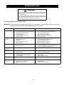
1
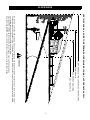
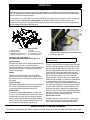
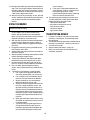
G1236
Walk-Behind Commercial
Rotary Mowers
Professional Turf Equipment
ES
OPERATOR’S AND SERVICE MANUAL
TABLE OF CONTENTS
Foreword
Safety Instructions
Slope Guide
Safety Labels
Product Specification
Assembly
Operation
Maintenance
Service and Adjustments
Off-Season Storage
Accessories and Attachments
Troubleshooting
3
4
7
8
10
11
12
17
21
24
24
25
MODEL NUMBER
Model Number.........................................................
Serial Number...........................................................
Date of Purchase......................................................
Record the model number, serial number and date of
purchase above.
2
FOREWORD
The Cub Cadet Commercial, Walk-Behind, Rotary Mowers have been developed
for use by professional landscapers, commercial lawn service companies, professional
turf managers and golf course superintendents. The machines incorporate many safety
features that should be studied by all operators and maintenance personnel before
use. The list of safety precautions should receive particular attention. This manual
presents the operating and maintenance instructions necessary to keep your Cub
Cadet Commercial mower at peak efficiency. If properly operated and maintained, your
Cub Cadet Commercial mower will give dependable and trouble-free service.
Although hazard control and accident prevention partially are dependent upon the
design and configuration of the equipment, these factors are also dependent upon the
awareness, concern, prudence, and proper training of the personnel involved in the
operation, transport, maintenance and storage of the equipment.
CAUTION: THE Cub Cadet Commercial, Walk-Behind, Rotary Mowers
should only be operated and maintained by thoroughly trained individuals.
The machines could cause serious injury to anyone who misuses them or
does not understand their operation. All operators and maintenance
personnel are urged to read this entire manual for their personal safety.
•
•
•
•
WARNING-For the State of California
The engine exhaust, some of its constituents, and certain vehicle components contain or emit chemicals
known to the State of California to cause cancer, birth defects or other reproductive harm.
This unit is equipped with an internal combustion engine and should not be used on or near any unimproved
forest-covered, brush-covered, or grass-covered land unless the engine’s exhaust system is equipped with a
spark arrester meeting applicable local or state laws (if any). If a spark arrester is used, it should be maintained in effective working order by the operator.
In the State of California, the above is required by law (Section 4442 of the California Public Resources
Code). Other States may have similar laws. Federal laws apply to federal lands. A spark arrester muffler
may be available.
WARNING-For the State of California
A person shall not sell, offer for sale, lease, or rent to a person any equipment that is powered by an internal
combustion engine subject to Section 4442 or 4443, and not subject to Section 13005 of Health and Safety
Code, unless that equipment has a permanent writing label attached that is in plain view to the operator that
states, ‘WARNING-Operation of This Equipment May Create Sparks That Can Start Fires Around Dry
Vegetation. A Spark Arrestor May be Required. The Operator Should Contact Local Fire Agencies For
Laws or Regulations Relating to Fire Prevention Requirements.’
NOTE: The engine manufacturer is responsible for all engine-related issues with
regards to performance, power-rating, specifications, warranty and
service. Please refer to the engine manufacturer’s owner’s/operator’s
manual, packed separately with your unit, for more information.
This product may be covered by one or more of the following patents:
D415,503; 5,928,097; 6,012,274; 5,355,665; 6,226,966; 6,266,949
3
SAFETY
WARNING: This symbol points out important safety instructions which, if not followed, could
endanger the personal safety and/or property of yourself and others. Read and follow all
instructions in this manual before attempting to operate this machine. Failure to comply with these
instructions may result in personal injury. When you see this symbol - heed its warning.
DANGER: This machine was built to be operated according to the rules for safe operation in this
manual. As with any type of power equipment, carelessness or error on the part of the operator can
result in serious injury. This machine is capable of amputating hands and feet and throwing objects.
Failure to observe the following safety instructions could result in serious injury or death.
GENERAL
OPERATION
1. Read this Operator’s Manual completely before
starting the mower. Study the controls and learn
the proper sequence of operation. Retain
Operator’s Manual in a safe place for future
reference.
WARNING: Never mow in fifth gear
(transport speed).
1. Keep adults, children and pets away from the
area to be mowed. (75 feet reccommended)
2. Never use this mower without the discharge
chute installed and set in the down position
(except when material collection system is used.)
3. Mow only in daylight or proper artificial light.
4. Always remove debris and other objects from the
area to be mowed.
5. Watch for holes, sprinkler heads and other
hidden hazards.
6. Reduce speed when making sharp turns.
7. Always have proper footing on slopes and hill
sides and never operate when conditions are
slippery.
8. Always keep both hands on the handles when
mowing. Always walk, never run.
9. Never engage the blade clutch when the engine
is running unless you are on grass that you intend
to mow.
10. Be careful when crossing gravel paths or roadways. Always disengage the blade clutch and
wait until the blades stop rotating.
11. Never leave the mower unattended without
disengaging the blade clutch, shifting the
transmission into neutral, placing the neutral latch
levers in the neutral lock position, shutting off the
engine, removing the key from the ignition switch
and closing the fuel shutoff valve.
12. Always park the mower and start the engine on a
level surface with the transmission in neutral, the
blade clutch disengaged and the neutral latch
levers in the neutral lock position.
13. Shut off the engine and wait for the blades to stop
rotating before removing the grass catcher.
14. If you hit a solid object while mowing, disengage
the blade clutch, shift the transmission into
neutral, place the neutral latch levers in the
neutral lock position and stop the engine.
Disconnect the spark plug wire(s) and inspect for
damage. Repair any damage and make sure the
IMPORTANT: If the operator cannot read English or
Spanish, the owner is responsible for explaining the
information in this manual.
2. Do not allow anyone to operate or maintain this
machine who has not read the manual. Never
permit children under the age of 16 to operate
this machine.
3. Always have your feet and hands clear of the
cutter deck when starting the engine.
4. Do not remove any shields, guards, decals or
safety devices. If a shield, guard, decal or safety
device is damaged or does not function, repair or
replace it before operating the mower.
5. Always wear safety glasses, long pants and
safety shoes when operating or maintaining this
mower. Do not wear loose-fitting clothing, or have
loose long hair or jewelry.
6. Never run the engine indoors without adequate
ventilation. Exhaust fumes are deadly.
7. To avoid serious burns, do not touch the engine
or muffler while the engine is running or until it
has cooled for at least 30 minutes after it has
been shut off.
8. Do not allow anyone to ride on this mower. No
passengers.
9. Do not operate this mower under the influence of
alcohol and or drugs.
10. Do not operate or store the machine or fuel
container inside where there is an open flame,
spark or pilot light such as a water heater,
furnace, clothes dryer, etc.
11. The owner is responsible for training the users,
and is responsible for accidents or injuries
occuring to themselves or others.
4
Observe proper disposal laws and regulations for gas,
oil, etc. to protect the environment.
blades are in good condition and the blade bolts are
tight before restarting the engine.
15. Do not mow excessively steep slopes (No more
than 15 degrees or a 26.8% grade). Mow across
the slope.
RELATED TO FUEL
1. Fuel is highly flammable and its vapors can explode
if ignited. Please respect it.
2. Do not smoke or permit others to smoke while handling fuel.
3. Always use approved containers for fuel and fill
slowly to decrease the chance of static electricity
buildup and spillage.
4. Store fuel in well ventilated and unoccupied buildings away from sparks and flames.
5. When dispensing gasoline into approved containers, place the container on the ground when refueling to avoid a possible static electricity ignition of
fuel vapors.
6. Do not fill containers while it is inside a vehicle,
trunk, the bed of a pickup or floor of a trailer.
7. Always shut off the engine and permit it to cool
before removing the fuel tank cap.
8. Always fill the fuel tank outdoors.
9. If the fuel container spout will not fit inside the fuel
tank opening, use a funnel.
10. When filling the fuel tank, stop when the fuel reaches
one inch from the top. This space is necessary for tank
expansion. Do not overfill.
11. Wipe up any spilled fuel.
12. Do not operate or store the machine or fuel
container inside where there is an open flame,
spark or pilot light such as a water heater, furnace,
clothes dryer, etc.
WARNING: Do not mow up and down
the slope. You could slip and slide into the
mower, or the mower could loose traction
and steering control.
16. Never raise the mower deck while the blades are
rotating.
17. Never walk or stand on the discharge side of a
mower with the engine running. Disengage the
blade clutch if another person approaches while
you are operating a mower.
18. Always disconnect the spark plug wire to prevent
the engine from accidentally starting before
performing any maintenance on this mower.
19. Keep the mower and especially the engine clean
and free of grease, grass and leaves to reduce the
chance of fire and to permit proper cooling.
20. The operator presence control levers located at
each handle are designed for your safety. Do not
try to defeat their operation. If the blade clutch is
engaged or the transmission is in gear, releasing
both handles will shut off the mower’s engine.
MAINTENANCE AND STORAGE
WARNING: Never let children or
untrained people operate or service this
mower.
SLOPE OPERATION
1. Never tamper with safety devices. Check their
proper operation regularly.
2. Check bolts and screws for proper tightness at
frequent intervals to keep the machine in safe
working condition. Also, visually inspect machine
for any damage and repair, if needed.
3. Before cleaning, repairing, or inspecting, stop the
engine and make certain all moving parts have
stopped. Disconnect the spark plug wire and
ground it against the engine to prevent unintended
starting.
4. Do not change the engine governor settings or
overspeed the engine. The governor controls the
maximum safe operating speed of the engine.
5. Maintain or replace safety and instruction labels, as
necessary.
6. Follow this manual for safe loading, unloading,
transporting, and storage of this machine. (See
page 16 and page 24)
7. Never store the machine or fuel container inside
where there is an open flame, spark or pilot light
such as a water heater, furnace, clothes dryer, etc.
8. Always refer to the operator’s manual for proper
instructions on off-season storage. (See page 24)
9. If the fuel tank has to be drained, do this outdoors.
DO:
• Mow across slopes, and exercise caution when
turning or changing direction.
• Watch for holes, ruts or bumps and hidden objects.
• Be sure of your footing. A slip could cause personal
injury.
• Check the area thoroughly before mowing.
• Slow down and use extra care.
DO NOT:
• Do not mow up and down slopes.
• Do not mow near drop offs, ditches, embankments,
etc. The mower could suddenly turn over if a wheel is
over the edge of a cliff or ditch, or if an edge caves in.
• Do not mow on wet or slippery grass. Reduced
traction could cause sliding.
• Do not mow on slopes greeater than 15 degrees as
shown on the slope gauge.
5
FIRST TIME OPERATORS
• Start off in a flat, open, area.
• Keep bystanders away.
• Set the throttle to low speed.
• Practice maneuvering (forward, turn left, turn right,
reverse), without the mower deck engaged.
6
SLOPE GUIDE
DO
ING
A1
5
°
S
LO P
E
OR A FENCE POST
A CORNER OF A BUILDING
A POWER POLE
SIGHT AND HOLD THIS LEVEL WITH A VERTICAL TREE
USE THIS PAGE AS A GUIDE TO DETERMINE SLOPES WHERE YOU MAY NOT OPERATE SAFELY.
FOL
N DO
TTE
D
L
INE,
R
E
P
RES
ENT
15°
WARNING
Do not mow on inclines with a slope in excess of 15 degrees (a rise of approximately 2-1/2 feet every 10 feet). A riding mower
could overturn and cause serious injury. If operating a walk-behind mower on such a slope, it is extremely difficult to maintain
your footing and you could slip, resulting in serious injury.
Operate ZERO-TURN mowers across the face of slopes, never up and down slopes.
Operate WALK-BEHIND mowers across the face of slopes, never up and down slopes.
7
SAFETY LABELS
WARNING
OPEN BELT DRIVE
STOP ENGINE BEFORE
REACHING UNDERNEATH
Part Number: 01001035
WARNING
Part Number: 777I22931
- TURN OFF ENGINE AND ALLOW
TO COOL BEFORE REFUELING.
- DO NOT SMOKE NEAR FUEL.
Part Number: 01001036
Part Number: 777I22930
Part Number: 777S30116
WARNING
SHIELD MISSING
DO NOT OPERATE
Part Number: 00030635
8
Part Number: 01006668
Part Number: 01006132
Part Number: 777S30503
Part Number: 777I22929
Part Number: 01002166
Part Number: 777D12837
9
PRODUCT SPECIFICATION
GENERAL INFO.
Controls:
Frame:
Front Caster Wheels:
Drive Wheels:
Fuel Tank:
Ground Speed:
(approximate)
Net Weight:
Engine ignition; throttle; choke; left and right operator presence
levers; left and right steering/brakes; blade clutch; transmission
shift
Transmission in 1st, neutral latches released, rear wheels
chocked in front
7 gauge steel
9 x 4.0-5 semi-pneumatic
13 x 6.50-6 pneumatic, 10-12 psi
5 gallons, regular unleaded
1st=2.0mph, 2nd=2.6mph, 3rd=3.1mph, 4th=4.0mph,
5th=6.0mph, Reverse=2.2mph
460 lbs
ENGINE INFO.
Engine:
Oil Type:
Spark plug:
12.5 Briggs I/C, recoil start, dual element air cleaner
SAE 15W40, 1.2 quart
759-3336, 0.030” gap
Parking:
TRACTION DRIVE INFO.
Traction Drive:
5 speed forward with reverse assist
CUTTER DECK INFO.
Cutter Deck; Drive:
Cutting Height:
No. of Blades
Spindle:
Pulleys:
36” fabricated steel; belt driven
2" to 4" in 1/4” increments
2 at 18” long
aluminum housing with taper roller bearings, greasable
machined-cast iron for drive
10
ASSEMBLY
IMPORTANT: This unit is shipped with oil in the engine.
After assembly, see OPERATION section of this
manual for fuel and engine oil details.
NOTE: Reference to right and left hand side of the
mower is observed from the operating position.
This pedestrian controlled wide area mower has been
completely assembled at the factory.
LOOSE PARTS IN CARTON
The following items are packaged in a bag:
Operator’s Manual and Engine Manual
TOOLS NEEDED FOR ASSEMBLY
A tire Gauge
REMOVING THE UNIT FROM THE CRATE
1. Cut straps securing unit to pallet.
2. Remove any protective packaging and plastic tie
straps.
REMOVING THE CHUTE STRAP
1. Locate the chute strap which secures the discharge
chute in a vertical position.
2. Pull chute back towards the engine. While holding
the chute with one hand, cut the strap with the other
hand.
FINAL ADJUSTMENTS
Tire Pressure
The recommended operating rear tire pressure is 1012 psi. The caster wheels are semi-pneumatic and do
not require air pressure. Check the tire pressure
periodically and maintain equal pressure in both rear
tires at all times.
IMPORTANT: Refer to the tire sidewall for exact tire
manufacturer;s recommended or maximum psi. Do not
overinflate. Uneven tire pressure could cause the
cutting deck to mow unevenly.
11
OPERATION
Know Your Mower
Read this operator’s manual and safety rules before operating your Mower. Compare the illustrations below
with your equipment to familiarize yourself with the location of various controls, safety signs and adjustments.
Save this manual for future reference.
The operation of any lawn mower can result in foreign objects being thrown into the eyes, which can damage
your eye severely. Always wear safety glasses, while operating the mower or while performing any
adjustments or repairs on it. Check local regulations, hard hats and hearing protection may be required! Use
only approved accessories and attachments.
6
2
1
7
4
8
5
3
Figure 1 The Control Panel
1. Ignition Switch
3. Engine Throttle
5. Right Steering Brake Lever
7. Operator Presence Lever
2. Choke
4. Blade Clutch lever
6. Neutral Latch Levers
8. Fuel Shutoff Valve
OPERATING CONTROLS (See Figure 1 & 2)
Ignition Switch:
Located in the center of the control panel between the
handles. When the key is inserted and turned
clockwise 90 degrees, the engine can be started if the
transmission shift lever is in neutral and the blade
clutch is disengaged.
Choke:
Located on the control panel and is activated by
pulling upward. Activating the choke control closes
the choke plate on the carburetor and aids in starting
the engine.
Engine Throttle:
Located on the right side of the control panel between
the handles. Moving the throttle lever upward will
increase the engine speed from slow to fast.
Blade Clutch:
Located on the left handle below the control panel.
This is an over-center belt clutch. When the handle is
pushed forward it snaps to rest and forces the idler
pulley into the blade drive belt causing the blades to
rotate. Pull back the handle and the pressure on the
belt is relieved and the blades stop rotating.
Figure 2 View Looking Under The Fuel Tank
9. Transmission Shift Lever
IMPORTANT: To avoid engine stalling, slowly
engage the lever.
Steering Brake Levers:
There is a right-hand lever located beneath the outer
end of the right handle and a left-hand lever located
beneath the outer end of the left handle. Each lever
operates independently and when squeezed against
spring tension, lifts the idler pulley from applying
pressure to the traction drive belt on the right or left
side and applies the right or left side brake when
squeezed tightly. When the levers are released, the
mower will move ahead in a straight line if the engine
is running and the transmission is engaged in a
forward gear. Steering is accomplished by squeezing
the steering/brake lever on the side to which the turn
is to be made. A slight lever squeeze will allow belt
slippage and provide a gentle turn. Squeezing the
lever such that the neutral latch could be engaged will
provide a sharp turn, and continued lever squeezing
will apply the brake providing a pivot turn.
Neutral Latch Levers:
Pivoted inside each handle, there is a neutral latch
lever which works with each of the steering/brake
levers. When either of the steering/brake levers is
Meets ANSI B71.4 safety standards
This pedestrian controlled wide area mower conforms to the safety standard of the American National Standards Institute (ANSI).
12
squeezed and its neutral latch lever pushed forward
and engaged in the neutral lock position, the
steering/brake lever is held in a position where the
idler pulley is not applying pressure to the traction
drive belt and the brake is not engaged.
must be in the Neutral position in order to start the
engine. Never attempt to mow in Fifth Gear. Fifth
Gear should be used for transport only.
Transmission
Shift Lever
neutral lock
position
Figure 5
IMPORTANT: DO NOT shift the transmission from
one forward gear to another while unit is moving.
Stop forward travel, shift gear, then resume
movement.
Figure 3
IMPORTANT: The neutral latch levers must be
engaged in the neutral lock position before starting
the engine. They should not be loose so that they will
stay in the unlocked position unless moved.
Operator Presence Levers:
Located above the outer ends of the right and left
handles, at least one of these operator presence
levers must be held down on the handles against
spring pressure in order to shift the transmission shift
lever into gear or engage the blade clutch. Releasing
the operator presence levers with either the
transmission shift lever in gear or the blade clutch
engaged will shut off the engine.
IMPORTANT: One or both operator presence levers
must be depressed when in gear or mowing.
Fuel Shutoff Valve:
Located on top of the fuel tank is the fuel shutoff
valve. The handle turns 90 degrees. When the
handle is in a horizontal position, it will shut off the
flow of fuel to the engine. When it is turned to a
vertical position, it will open and allow fuel to flow to
the engine. Anytime the mower is being trailered or, if
the mower will not be in use for 30 minutes or more,
close the fuel shutoff valve to prevent flooding the
engine.
GAS AND OIL FILL-UP
Oil
IMPORTANT: The mower is shipped with motor oil in
the engine; however, you MUST check the oil level
before operating. Oil should be changed once after
the first five hours of operation and every 40 hours of
operation thereafter. Use the grade of engine oil
specified in the Maintenance section.
•
•
Remove oil fill dipstick from the oil fill tube.
Check that the level of oil is up to the FULL mark
on the dipstick. If needed, pour oil slowly into the
oil fill tube until a FULL oil level is achieved.
• Replace oil fill dipstick and tighten.
Gasoline
•
•
•
Fuel Shutoff
Valve
•
DANGER: Never refuel or drain the fuel
Figure 4
system indoors, or operate or store near an
open flame, spark, or ignition source.
Transmission Shift Lever:
Located under the control panel. The lever has
seven positions moving from the left to the right:
Reverse Gear, Neutral, First Gear, Second Gear,
Third Gear, Fourth Gear and Fifth Gear. The lever
Remove fuel cap from the fuel tank.
Make sure the container from which you will pour
the gasoline is clean and free from rust or foreign
particles. Never use gasoline that may be stale
from long periods of storage in its container.
Gasoline that has been sitting for any period
longer than four weeks should be considered
stale.
Fill fuel tank with clean, fresh, unleaded regular
gasoline (87 ROM) only no more than one inch
below bottom of filler neck to provide space for
fuel expansion. Replace fuel cap.
To avoid engine problems, the fuel system should
be emptied before storage for 30 days or longer.
Drain the fuel by shutting off the fuel valve and
running the engine until it stops. Use fresh fuel
next season. See STORAGE section for
additional information.
•
13
Check the fuel level periodically to avoid running
out of gasoline while operating the mower.
INITIAL ADJUSTMENTS
needed.
1. Disconnect the spark plug wire.
2. Check that all nuts, bolts and screws are tight.
Hair Pin
3. Check the tension of the deck drive belts:
a. Remove the deck cover shield and engage
the blade clutch.
b. Make sure the belts clear the belt guides by
1/8" to 1/4".
c. The tension of the deck drive belts should
be adjusted so that a ten-pound pull
between two pulleys deflects each belt
about 1/2" (See Figure 19 page 19). Do not
overtighten these belts. The blade clutch
should engage with only moderate force.
d. Replace the deck cover shield and
disengage the blade clutch.
4. The tension of the transmission drive belt should
be adjusted so that a five-pound pull between
the engine traction drive pulley and the
transmission drive pulley deflects the belt about
3/16". (See Figure 20 page 20)
5. The two drive wheel belts are self-adjusting.
6. The steering control rods on each side of the
handle assembly should initially be adjusted so
that there is about a 1/4" to 3/8” space between
the rod and the bottom of the slot in the neutral
latch lever with the latch in the drive position (See
Figure 6.) To make this adjustment, remove the
large hairpin from the swivel joint at the bottom of
each steering control rod and thread the swivel
joint up or down the rod as needed.
Figure 7
8. Adjusting the cutting height: The mower is
shipped with the cutting height set at 3 inches ±1/
4 inch depending on the air pressure in the tires.
To change the cutting height, blade spacers and/
or caster spacers must be moved according to
the cutting height adjustment table. (Figure 24
and 25, page 22)
9. Lubricate all fittings listed in the maintenance
section.
TO START THE MOWER
IMPORTANT: First time operators should refer to the
procedure stated on page 5.
WARNING: Never run the engine
indoors or in a poorly ventilated area.
Engine exhaust contains carbon
monoxide, a deadly, odorless gas.
1. Make certain you thoroughly understand all of
the safety precautions before you attempt to
operate this machine.
2. Move the mower outdoors to a “test area” where
you can operate the mower for about half an
hour without being disturbed.
3. Shift the transmision to neutral (N) position.
4. Disengage the blade clutch.
5. Place the neutral latch levers in the neutral lock
position.
1/4” to 3/8”
6. Connect the spark plug wire.
7. Open the fuel shutoff valve.
Figure 6
8. Move the throttle lever to a mid range position
and pull the “Choke” all the way out.
7. The brake rods (above each drive wheel) should
be adjusted so that when the steering/brake
levers are squeezed and the mower is pulled
backward, the brakes lock the drive wheels. The
machine should roll freely when the neutral latch
lever is in the neutral lock position. To adjust the
brake rods, remove the large hairpin from the
swivel joint at the top of each brake rod and
thread the swivel joint up or down the rod as
9. Put the key in the ignition switch and turn the
switch on.
10. To start engine using recoil starter:
a. Stand on left side (as viewed from behind
handlebars) of machine. Be sure your feet
are safely away from the underside of the
mower deck and all mower controls are
released. Stabilize mower by placing foot
14
2. With the neutral latch levers engaged restart the
engine.
3. Push the blade clutch lever forward until it
engages and the cutter blades start rotating.
4. Shift the transmission into first gear. (It is
suggested that you practice mowing in first gear.)
5. Squeeze both steering/brake levers with both
hands and release the neutral latch levers from the
neutral lock position.
6. Slowly release the steering/brake levers and the
mower will move ahead in a straight line. To turn
the mower, squeeze the steering/brake lever on
the side to which you want to turn.
7. To stop the mower’s forward motion, squeeze both
steering/brake levers until the mower stops and
place the neutral latch levers into the neutral lock
position.
as indicated below in Figure 8.
Figure 8
b. Grasp starter rope handle and pull slowly
until rope pulls slightly harder. Let rope
rewind slowly. Then pull rope with a rapid,
full arm stroke. Let rope return slowly. If
engine fails to start after three pulls, repeat
instructions (try setting throttle at fast
setting).
c. When engine starts, operate in fast throttle
setting (move choke control to off).
IMPORTANT: Squeezing the control levers from the
released position to the Neutral lock position releases
traction-drive belt tension. Additional squeezing of
these levers applies the service brakes. Applying the
left brake will create a counter clockwise pivot or uturn and applying the right brake will create a
clockwise pivot or u-turn. Applying both brakes will
stop the machine without turning.
KNOW YOUR MOWER
8. Before shifting into reverse gear, the mower’s
forward motion must be completely stopped. For
maximum traction in reverse, the steering/brake
levers should be pushed downward.
1. After the engine has warmed up, shut off the
ignition and check the operation of the safety
switches. Make certain that the engine will not
start unless the ignition switch is turned on, the
transmission is in neutral and the blade clutch is
disengaged. Place the neutral latch levers in the
neutral lock position. If the engine will start with
the transmission in any gear (not neutral),
immediately shut off the engine and contact
customer service. If the engine will start with the
blade clutch engaged, immediately shut off the
engine and contact customer service. To check
operator presence controls:
DANGER: Look behind the mower before
and during Reverse operation. Stop the mower
blades before operating in Reverse.
WARNING: To avoid possible bodily injury
and to prevent damage to the transmission,
the mower must be completely stopped before
attempting to shift from forward to reverse or
reverse to forward.
9. Practice operating the mower and as you gain
confidence, shift the transmission from first to
second and mow for a while and then shift from
second to third. Mow for at least one-half hour
and then return the mower to the shop.
a. Start the engine and hold the left operator
presence control lever down against the left
handle and move the transmission shift
lever into first gear. Now take your hand off
the operator presence control lever and the
engine should die. If it does not, immediately
shut off the engine and contact customer
service.
b. Repeat this procedure using the right
operator presence control lever.
c. Shift the transmission into neutral, restart
the engine, hold one of the operator
presence controls down against the handle
and engage the blade clutch. Now take your
hand off of the operator presence lever and
the engine should die. If it does not,
immediately shut off the engine and
disengage the blade clutch and contact
customer service.
WARNING: The machine should not be
shifted-on-the-go as transmission damage
could occur, causing the machine to suddenly
stop! Stop the machine, then shift.
10. To stop and shut off the mower, squeeze both
steering/brake levers and place the neutral latch
levers into the neutral lock position, disengage the
blade clutch, shift the transmission into neutral,
turn off the ignition to stop the engine, close the
fuel shutoff valve and disconnect the spark plug
wire.
11. Check that all nuts, bolts and screws are still tight.
12. Check, and adjust if necessary, the tension of the
deck drive belts and the transmission drive belt as
described in items 3 and 4 of the Initial Adjustment
section
15
area is mowed.
g. If the grass is repeatedly mowed in the
same direction, it will be “trained” so that
the Striped appearance is more
pronounced and longer lasting. Grooving
of the turf from the tires will occur.
10. For empting material collection systems or for
any other operation involving the mower deck,
before leaving the operator station:
• shut off the mower deck.
• place the transmission in neutral.
• latch the neutral locks.
• shut off the engine.
• apply wheel chocks.
13. Readjust the steering control rods and the brake
rods. They may require frequent adjustment until
the belts and brake bands have properly seated.
These adjustments are described in items 6 and
7 of the Initial Adjustment section.
14. After the first full day of mowing, all nuts, bolt and
screws should be rechecked for proper tightness
and the belts should be rechecked for proper
tension.
USING THE MOWER
IMPORTANT: First time operators should refer to the
procedure stated on page 5.
1. Be sure area is clear of rocks, sticks, toys, wire,
or other objects that could be thrown by the
mower. Survey the entire area to be mowed.
Make sure that the accessories and attachments
would be suitable for use on the terrain.
2. With the neutral latches locked and the operator
presence levers depressed, select a mowing
speed. (a slower speed is suggested during first
time use.)
3. Engage the mower by pushing the blade clutch
lever forward until it locks.
4. Squeeze the steering control levers and release
the neutral latches.
5. Slowly release the steering control levers and the
mower should go straight ahead.
6. To operate in Reverse, look behind and down
before backing up to be sure the path is clear.
7. Be aware of the mower discharge and do not
point it at anyone, or onto sidewalks and streets.
8. Use care when approaching blind corners,
shrubs, trees or other objects that could obstruct
vision.
9. To mow grass and produce a striped pattern:
a. Pick a point on the opposite side of the
area to be mowed (post, tree, shrub, etc).
b. If on a hillside, start at the bottom so that
the turns are uphill rather than downhill.
c. Align the mower so as to head directly
toward the object on the far side.
d. Slowly increase the speed of the machine
to match cutting conditions, terrain, and
operator familiarity with the controls and
keep the machine headed directly toward
the alignment object. Do not go fast as to
reduce cut quality or to be uncomfortable in
controlling the speed and direction of the
machine.
e. When approaching the other end of a strip,
slow down or stop before turning. A U-turn
is recommended.
f. To prevent rutting or grooving of the turf,
change the direction that the strips are
mowed by approximately 45 degrees the
next and each subsequent time that the
TRANSPORTING MOWER
1. If ramps are used, be sure they are secured to
the trailer, truck bed, etc. and are designed for
the application.
2. The mower should be pushed or pulled onto or off
the trailer, truck bed, etc., never try to drive it on.
3. Turn the fuel valve off.
4. Secure mower with chocks, straps, etc.
5. Make sure accessories and attachments are
secured or removed.
16
MAINTENANCE
GENERAL RECOMMENDATIONS
•
WARNING: Never let children or untrained
Transmission-Jackshaft Couplers- There are
two grease positions. See Figure 11 item H
people operate or service the mower.
•
•
•
•
Always observe safety rules when performing any
type of maintenance on the mower.
The warranty on this lawn mower does not cover
items that have been subjected to operator abuse
or negligence. To receive full value from the
warranty, operator must maintain the equipment as
instructed in this manual.
Changing of engine-governed speed will void
engine warranty.
Periodically check all fasteners and make sure they
are tight.
WARNING: Always stop the engine and
disconnect and ground the spark plug wire
before performing any maintenance or
adjustments.
Figure 9
Engine Oil: Use Shell Rimula 15W40 oil or any 10W30
or 15W40 oil rated SJ or higher.
Spindle Lubricant: Use only Shell Alvania RL 2
grease. This grease is an amber-colored grease
designed for high speed bearing applications. It has a
base oil viscosity that reduces running losses, has
been formulated for low noise, has excellent corrosion
protection, and has excellent bearing lubrication.
General Purpose Lubrication: Use any NLGI grade 2
multi-purpose grease. Shell Albida EP2 is recommended. Shell Albida EP 2 is a red-colored multi-purpose grease designed for heavy-duty bearing
applications. It has high base oil viscosity for mechanical stability, has been formulated for high load, lowspeed applications, and has excellent lubrication and
corrosion protection.
Figure 10
LUBRICATION (See Figures 9, 10 & 11)
Daily
•
Cutter Blade Spindle Bearings- There are two
grease positions. See Figure 9 item A.
• Caster Wheel Bearing- There are two grease
positions. See Figure 9 item B.
• Caster Wheel Pivot Shafts- There are two grease
positions. See Figure 9 item C.
• Deck Idler Pulley Pivot Arms- There is one
grease position. See Figure 9 item D.
Every 40 Hours
•
•
•
G
H
View looking from the front
Figure 11
Drive Wheel Bearings- There are two grease
positions. See Figure 10 item E.
Brake Lever Pivots- There are two grease
positions. See Figure 10 item F.
Blade Clutch Bellcrank Pivot- There is one
grease position. See Figure 11 item G.
ENGINE MAINTENANCE
For detailed maintenance instructions for the engine
on your mower, see the separate engine manual
packed with your mower.
17
CHANGING ENGINE OIL
3. Remove old filter and insert new filter into hoses,
and move clamps near filter.
1. Place a container underneath the mower on the
right hand side.
2. Remove oil drain plug, and replace when oil stops
draining. (See Figure 12)
Clamp
Fuel Filter
Clamp
Drain
Plug
Figure 15
SERVICE SPARK PLUG
WARNING: Do not at any time make any
adjustment to the unit without first stopping
engine and disconnecting spark plug wire.
Figure 12
3. Refill oil through the fill tube to the level indicated
as “full” on the dipstick. (See Figure 13)
•
Full
Clean the spark plug and reset the gap to.030" at
least once a season or every 50 hours of operation.
See Figure 16. Spark plug replacement is
recommended at the start of each season. Refer to
engine parts list for correct spark plug type.
NOTE: Do not sandblast spark plug. Spark plug
should be cleaned by scraping or wire brushing and
washing with a commercial solvent.
.030" Gap Gauge
Figure 13
CHANGING THE AIR FILTER
Spark Plug
1. Pull cover to open and expose filter.
2. Remove and replace filter.
3. Close cover.
Figure 16
CHANGING A BLADE (See Figure 17 & 18)
Latch
WARNING: Mower blades are sharp. Wear
gloves or wrap blades to protect yourself from
the sharp edges.
Air Filter
1. Remove the deck cover.
cover
2. Tip the mower back and block up the front of the
deck.
3. Place one wrench on the hex head bolt under the
blade. Use a second wrench to remove the locknut
on top of the spindle pulley.
4. Remember the number of blade spacers both
Figure 14
CHANGING THE FUEL FILTER
1. Squeeze the clamps on either side of the fuel filter
hose, and move them away from the filter
approximately one inch.
2. Pull the hoses off the filter.
18
2. Remove the deck cover. (This requires a 9/16”
wrench)
3. Remove the cap screw which serves as a belt
guide and is mounted in the idler pulley arm.
(Item J, Figure 19.)
4. Slip the long blade drive belt off of the pulleys.
5. Place a new long blade drive belt through the belt
guide and loop it around the engine pulley and
then around the two deck pulleys. The belt’s back
side should ride on the idler pulley.
6. Replace the cap screw, lock washer and nut in
the idler pulley arm.
7. The idler pulleys should be adjusted so that when
the blade clutch is engaged, a ten-pound pull
between two pulleys deflects either belt about 1/
2" (See Figure 18.) Do not overtighten these
belts. The blade clutch should engage with only
moderate force.
8. Replace the deck cover, and secure with 9/16”
nut.
above and below the spindle.
1/4” Spacer
1/4” Spacers
Figure 17
5. Remove the long (9-1/2”) blade bolt, the flat
washer, the blade and the blade spacers.
6. To replace the blade, reverse the above
procedure. Be careful to replace the blade
spacers correctly above and below the spindle.
This is not a timed blade system and since blade
overlap is provided, orientation is not important.
J
1/2” deflection
Figure 19
CHANGING THE TRANSMISSION DRIVE
BELT: (See Figure 20)
Figure 18
SHARPENING A BLADE
1. Make sure the blade clutch is disengaged.
1. To sharpen a blade, clamp the blade in a vise
and, using a flat mill file, carefully file the cutting
surface on each end of the blade to a sharp
edge.
2. Working under the engine deck, take the long
blade drive belt off of the engine pulley.
3. Loosen the locknut (item I, Figure 20) holding the
transmission drive belt idler pulley in place and
slide the pulley away from the transmission drive
belt.
4. Remove the old belt and mount a new belt onto
the pulleys.
5. Slide the idler pulley back onto the belt and
tighten the locknut holding it in place. The idler
pulley should be adjusted so that a five-pound
pull on the belt between the engine pulley and the
transmission pulley deflects the belt about 3/16".
2. Blades with severe nicks or dents that cannot be
removed by filing should be replaced.
3. It is important that each cutting blade edge be
ground equally to maintain proper blade balance.
A poorly balanced blade will cause excessive
vibration and may cause damage to the mower
and result in personal injury. The blade can be
tested by balancing it on a round shaft
screwdriver. Grind metal from the heavy side until
it balances evenly.
CHANGING THE BLADE DRIVE BELTS
(See Figure 19)
1. Make sure the blade clutch is disengaged.
19
5. Prop up the side of the mower and slip the belt
over the drive wheel.
6. Slip the new traction drive belt over the drive
wheel and loop it over the jackshaft pulley while
lifting up on the idler bracket.
7. Insert the swivel joints in the holes in the idler
bracket and replace the hairpin cotters.
8. Replace the belt guards and the hex screws.
6. Replace the long blade drive belt on the engine
pulley.
transmission
drive belt
I
CHANGING A SPINDLE ASSEMBLY
1. Make sure the blade clutch is disengaged.
3/16” deflection
2. Remove the deck cover.
3. Remove the blade. (See changing a blade on
page 18.)
4. Remove the blade drive belts. (See changing the
blade drive belts on page 19.)
5. Remove the pulley.
6. Tip the mower back and block up the front of the
deck.
7. Remove the four bolts and locknuts holding the
spindle assembly to the deck.
8. Remove the spindle assembly.
long blade drive belt
Figure 20
CHANGING EITHER TRACTION DRIVE
BELT:
1. Remove the hex screws which hold the belt
guards in place. Remove the belt guards.
Hex Screws
Figure 21
2. Place the neutral latch lever in the neutral lock
position.
3. Remove the hairpin cotters from the two swivel
joints which are inserted through the idler bracket
and remove the swivel joints from the idler
bracket.
4. Lift up on the idler bracket with one hand while
removing the belt from the jackshaft pulley with
the other hand. (See Figure 22.)
Figure 22
20
SERVICE AND ADJUSTMENTS
WARNING: Do not at any time make any
adjustment to the unit without first
stopping engine and disconnecting
spark plug wire.
6.
ADJUSTING THE CONTROL-FORCE
7.
Three holes in the belt guard allow you to reposition
the hex cap screw to adjust the brake lever. The top
hole (lite tension), the middle hole (medium tension)
and the lower hole (hard tension). The unit is shipped
with the hex screw in the top hole. SEE FIGURE 25
BELOW FOR REFERENCE. To adjust the bolt do the
following:
8.
9.
are having difficulty removing the bolt, continue to
loosen the lower nut on the inner belt guard (BUT
DO NOT REMOVE). Remove the bolt and nut.
(See Figure 25)
Reposition the bolt and nut into the middle or
lower hole and retighten the nut. (See Figure 25)
Using a spring puller, reattach the spring to the
hex cap screw. (See Figure 23)
Reposition the inner belt guard, reinstall the
upper nut, and retighten the lower and upper
nuts. (See Figure 25)
Reposition the outer belt guard, reinstall the hex
screws. (See Figure 21 page 20)
1. Remove the hex screws retaining the outer belt
guard. (See Figure 21 page 20)
2. Remove the upper nut retaining the inner belt
guard, and loosen the lower nut (DO NOT
REMOVE). (See Figure 25)
3. With a spring puller, pull the spring and detach it
from the hex cap screw. (See Figure 23)
Upper Nut
Lite
Medium
Hard
Inner Belt Guard
Loosen the lower nut (DO NOT REMOVE)
Hex Cap Screw
Figure 25
Spring
Figure 23
4. Remove the lock nut from the lite touch hole in
the inner belt guard. (See Figure 24)
Lock Nut
Figure 24
5. Pull the inner belt guard away from the unit. This
will give clearance to remove the bolt. Note: If you
21
CUTTING HEIGHT ADJUSTMENT TABLE
Note: The front edge of the cutting deck should be 1/8” - 1/4” below the rear edge of the deck so that the blades are
cutting grass in only the front half of their circular path. This decreases friction and reduces the drive power required.
1/4” Spacer
1/2” Spacer
1/2” Spacers
1/4” Spacers
Figure 25
Figure 24
Approximate
Cutting Height
1/4”: Blade Spacers
Above and Below The
Spindle Assemblies
(See Figure 24)
1/2” Caster Spacers Above
and Below The Caster
Bracket
(See Figure 25)
Inches
Above
Below
Above
Below
2
2-1/8
2-3/8
2-1/2
2-3/4
3
3-1/4
3-1/2
0
1
2
1
2
3
4
5
5
4
3
4
3
2
1
0
3
3
3
2
2
2
2
2
1
1
1
2
2
2
2
2
2-3/4
3
3-1/4
3-1/2
3-3/4
3-1/4
3-1/2
3-3/4
4
0
1
2
3
4
0
1
2
3
5
4
3
2
1
5
4
3
2
2
2
2
2
2
1
1
1
1
2
2
2
2
2
3
3
3
3
22
Engine Deck bolted to
upper holes on cutting
deck.
AS DELIVERED
Engine Deck bolted to
lower holes on cutting
deck.
MAINTENANCE SCHEDULE
WARNING
Before performing any type of maintenance/service,
disengage all controls and stop the engine. Wait until
all moving parts have come to a complete stop.
Disconnect spark plug wire and ground it against the
engine to prevent unintended starting. Always wear
safety glasses during operation or while performing
any adjustments or repairs.
Interval
Follow the maintenance schedule given below. This chart describes
service guidelines only. Use the Service Log column to keep track of
completed maintenance tasks.
Item
Service
Each Use
1. Mower Blades
2. Loose or missing hardware
3. Belts
4. Engine oil level
5. Fuel level
6. Controls
7. Cutter Blade Spindle Bearings
1. As required
2. Tighten or replace
3. Check
4. Check
5. Check
6. Check for proper orientation
7. Lubricate
1st 5 hours
1. Engine oil
1. Change
40 hours
1. Engine oil
2. Air cleaner
3. Mower blades
4. Spark plug
5. Follow lubrication chart
1. Change
2. Clean or replace
3. Sharpen and balance
4. Clean, replace, re-gap
5. Lubricate
Before Storage
1. Fuel System
1. Run engine until it stops from
lack of fuel or add a gasoline
additive to the gas in the tank.
23
Service Log
OFF-SEASON STORAGE
WARNING
Never store lawn mower with fuel in tank indoors or in
poorly ventilated areas where fuel fumes may reach
an open flame, spark, or pilot light as on a furnace,
water heater, clothes dryer, or gas appliance. Never
refuel or drain the fuel system indoors.
PREPARING THE ENGINE
PREPARING THE LAWN MOWER
For engines stored over 30 days:
1. To prevent gum from forming in fuel system or on
carburetor parts, turn off the fuel valve, run the
engine until it stops from lack of fuel or add a gasoline additive to the gas in the tank. If you use a gas
additive, run the engine for several minutes to circulate the additive through the carburetor, after which
the engine and fuel can be stored up to six months.
2. While engine is still warm, change the oil.
3. Remove spark plug and pour approximately 1 oz.
(30 ml) of clean engine oil into the cylinder. Pull the
recoil starter several times to distribute the oil, and
reinstall the spark plug.
4. Clean engine of surface debris.
•
•
•
When storing the mower in an unventilated or metal
storage shed, care should be taken to rustproof the
non-painted surfaces. Using a light oil or silicone,
coat the equipment, especially any springs, bearings, and cables.
Remove all dirt from exterior of engine and equipment.
Store equipment in a clean, dry area. Do not store
in an area where equipment is present that may use
a pilot light or has a component that can create a
spark, or open flame.
ACCESSORIES AND ATTACHMENTS
PART NO.
DESCRIPTION
590-522-150
Bagger Grass Collector
590-512-150
Mulch Kit
24
TROUBLESHOOTING
WARNING
Before performing any type of maintenance/service, disengage all
controls and stop the engine. Wait until all moving parts have come
to a complete stop.
Disconnect spark plug wire and ground it against the engine to prevent unintended starting. Always wear safety glasses during operation or while performing any adjustments or repairs.
This section addresses minor service issues.
IMPORTANT: Before performing any troubleshooting, make sure: transmission is in Neutral, Neutral latches are locked on
the control levers, blade clutch is disengaged and in the “OFF” position.
Problem
Cause
Remedy
Engine fails to start
1.
2.
3.
4.
5.
6.
Choke not activated
Throttle/choke control not in correct position
Spark plug wire disconnected
Faulty spark plug
Fuel tank empty or stale fuel
Blocked fuel line
1.
2.
3.
4.
5.
6.
Place throttle/choke control lever into choke position..
Place throttle/choke lever into fast position.
Connect wires to spark plug.
Clean, adjust gap, or replace.
Fill tank with clean, fresh gasoline.
Clean the fuel line.
Engine runs
erratically
1.
2.
3.
4.
5.
Unit running with choke applied
Spark plug wire loose
Stale fuel.
Water or dirt in fuel system.
Dirty air cleaner
1.
2.
3.
4.
5.
Move throttle/choke lever out of choke position.
Connect and tighten spark plug wire.
Fill tank with fresh gasoline.
Drain fuel. Refill with fresh fuel.
Replace air cleaner cartridge.
Engine overheats
1.
2.
Engine oil level low
Air flow restricted
1.
2.
Fill engine with proper amount and type of oil.
Clean grass clippings and debris from around the
engine’s cooling fins and blower housing.
Engine hesitates at
high RPM’s
1.
Spark plug gap set too close
1.
Remove spark plug and adjust gap
Engine idles poorly
1.
2.
Fouled spark plug
Dirty air cleaner
1.
2.
Replace spark plug and adjust gap.
Replace air cleaner cartridge.
Excessive vibration
1.
2.
3.
Cutting blades loose or unbalanced
Damaged, dull, or bent cutting blade
Loose hardware
1.
2.
3.
Tighten blade and spindle. Balance blade.
Replace blade.
Tighten all nuts and bolts.
Unit fails to propel
itself
1.
Drive belts loose or damaged
1.
Replace drive belt.
Poor mowing
performance
1.
2.
3.
Dull blade(s)
Broken, loose, or worn belt(s)
Blade(s) out of balance
1.
2.
3.
Sharpen or replace blade(s).
Replace belt(s).
Balance or replace blade(s).
25
CALIFORNIA EMISSION CONTROL WARRANTY STATEMENT
YOUR WARRANTY RIGHTS AND OBLIGATIONS
The California Air Resources Board and MTD Consumer Group Inc are pleased to explain the evaporative emission control system warranty on your 2008 lawn
mower. In California, new lawn mowers must be designed, built and equipped to meet the State’s stringent anti-smog standards. MTD Consumer Group Inc must
warrant the EECS on your lawn mower for the period of time listed below provided there has been no abuse, neglect or improper maintenance of your lawn mower.
Your EECS may include parts such as the carburetor, fuel-injection system, the ignition system, catalytic converter, fuel tanks, fuel lines, fuel caps, valves,
canisters, filters, vapor hoses, clamps, connectors, and other associated emission-related components.
Where a warrantable condition exists, MTD Consumer Group Inc will repair your lawn mower at no cost to you including diagnosis, parts and labor.
MANUFACTURER’S WARRANTY COVERAGE:
This evaporative emission control system is warranted for two years. If any evaporative emission-related part on your equipment is defective, the part will be
repaired or replaced by MTD Consumer Group Inc.
OWNER’S WARRANTY RESPONSIBILITIES:
As the lawn mower owner, you are responsible for performance of the required maintenance listed in your owner’s manual. MTD Consumer Group Inc recommends
that you retain all receipts covering maintenance on your lawn mower, but MTD Consumer Group Inc cannot deny warranty solely for the lack of receipts.
As the lawn mower owner, you should however be aware that MTD Consumer Group Inc may deny you warranty coverage if your lawn mower or a part has failed
due to abuse, neglect, or improper maintenance or unapproved modifications.
You are responsible for presenting your lawn mower to MTD Consumer Group Inc’s distribution center or service center as soon as the problem exists. The
warranty repairs should be completed in a reasonable amount of time, not to exceed 30 days. If you have a question regarding your warranty coverage, you should
contact the MTD Consumer Group Inc Service Department at 1-800-800-7310.
GENERAL EMISSIONS WARRANTY COVERAGE:
MTD Consumer Group Inc warrants to the ultimate purchaser and each subsequent purchaser that the lawn mower is: Designed, built and equipped so as to
conform with all applicable regulations; and free from defects in materials and workmanship that cause the failure of a warranted part to be identical in all material
respects to that part as described in MTD Consumer Group Inc’s application for certification.
The warranty period begins on the date the lawn mower is delivered to an ultimate purchaser or first placed into service. The warranty period is two years.
Subject to certain conditions and exclusions as stated below, the warranty on emission-related parts is as follows:
1. Any warranted part that is not scheduled for replacement as required maintenance in the written instructions supplied, is warranted for the warranty period
stated above. If the part fails during the period of warranty coverage, the part will be repaired or replaced by MTD Consumer Group Inc according to subsection
(4) below. Any such part repaired or replaced under warranty will be warranted for the remainder of the period.
2. Any warranted part that is scheduled only for regular inspection in the written instructions supplied is warranted for the warranty period stated above. Any such
part repaired or replaced under warranty will be warranted for the remaining warranty period.
3. Any warranted part that is scheduled for replacement as required maintenance in the written instructions supplied is warranted for the period of time before the
first scheduled replacement date for that part. If the part fails before the first scheduled replacement, the part will be repaired or replaced by MTD Consumer
Group Inc according to subsection (4) below. Any such part repaired or replaced under warranty will be warranted for the remainder of the period prior to the
first scheduled replacement point for the part.
4. Repair or replacement of any warranted part under the warranty provisions herein must be performed at a warranty station at no charge to the owner.
5. Notwithstanding the provisions herein, warranty services or repairs will be provided at all of our distribution centers that are franchised to service the subject
engines or equipment.
6. The lawn mower owner will not be charged for diagnostic labor that is directly associated with diagnosis of a defective, emission-related warranted part,
provided that such diagnostic work is performed at a warranty station.
7. MTD Consumer Group Inc is liable for damages to other engine or equipment components proximately caused by a failure under warranty of any warranted
part.
8. Throughout the lawn mower warranty period stated above, MTD Consumer Group Inc will maintain a supply of warranted parts sufficient to meet the expected
demand for such parts.
9. Any replacement part may be used in the performance of any warranty maintenance or repairs and must be provided without charge to the owner. Such use will
not reduce the warranty obligations of MTD Consumer Group Inc.
10. Add-on or modified parts that are not exempted by the Air Resources Board may not be used. The use of any non-exempted add-on or modified parts by the
ultimate purchaser will be grounds for disallowing a warranty claims. MTD Consumer Group Inc will not be liable to warrant failures of warranted parts caused
by the use of a non-exempted add-on or modified part.
26
WARRANTED PARTS:
The repair or replacement of any warranted part otherwise eligible for warranty coverage may be excluded from such warranty coverage if MTD Consumer Group
Inc demonstrates that the lawn mower has been abused, neglected, or improperly maintained, and that such abuse, neglect, or improper maintenance was the
direct cause of the need for repair or replacement of the part. That notwithstanding, any adjustment of a component that has a factory installed, and properly
operating, adjustment limiting device is still eligible for warranty coverage. The following emission warranty parts are covered:
(1) Fuel Metering System
s#OLDSTARTENRICHMENTSYSTEMSOFTCHOKE
s#ARBURETORANDINTERNALPARTS
s&UELPUMP
s&UELTANK
(2) Air Induction System
s!IRCLEANER
s)NTAKEMANIFOLD
(3) Ignition System
s3PARKPLUGS
s-AGNETOIGNITIONSYSTEM
(4) Exhaust System
s#ATALYTICCONVERTER
s3!)2EEDVALVE
(5) Miscellaneous Items Used in Above System
s6ACUUMTEMPERATUREPOSITIONTIMESENSITIVEVALVESANDSWITCHES
s#ONNECTORSANDASSEMBLIES
(6) Evaporative Control
s&UELHOSECERTIFIEDFOR!2"EVAPORATIVEEMISSIONS
s&UELHOSECLAMPS
s4ETHEREDFUELCAP
s#ARBONCANISTER
s6APORLINES
'$/#2EV#
27
MANUFACTURER’S LIMITED WARRANTY FOR CUB CADET COMMERCIAL
WIDE AREA WALK-BEHIND COMMERCIAL MOWER
IMPORTANT: To obtain warranty coverage owner may be required
present proof of purchase and applicable maintenance records to the
servicing dealer. Please see the operator’s manual for information on
required maintenance and service intervals. In addition, Cub Cadet
may deny warranty coverage if the hour meter, or any part thereof, is
altered, modified, disconnected or otherwise tampered with.
The limited warranty set forth below is given by Cub Cadet LLC with
respect to new merchandise used for commercial and related purposes
purchased and used in the United States and/or its territories and
possessions, and by MTD Products Limited with respect to new
merchandise purchased and used in Canada and/or its territories and
possessions (either entity respectively, “Cub Cadet”).
Cub Cadet warrants this product (excluding its No-Fault Components,
and Batteries as described below) against defects in material and
workmanship for a period of two (2) years from the date of original
retail purchase or lease and will, at its option, repair or replace, free of
charge, any part found to be defective in materials or workmanship.
Batteries have a one-year prorated limited warranty against defects in
material and workmanship, with 100% replacement during the first
three months. After three months, the battery replacement credit is
based on the months remaining in the twelve (12) month period dating
back to the original date of original sale or lease. Any replacement
battery will be warranted only for the remainder of the original warranty
period.
No-Fault Components include only belts, tires, seats and grass bags
which are warranted to be free from defects in material and
workmanship for a period of thirty (30) days from the date of original
purchase or lease.
HOW TO OBTAIN SERVICE: Warranty service is available, WITH
PROOF OF PURCHASE AND APPLICABLE MAINTAINCE
RECORDS, through your local authorized service dealer. To locate the
dealer in your area;
In the U.S.A.:
Check your Yellow Pages, or contact Cub Cadet LLC at P.O. Box
361131, Cleveland, Ohio 44136-0019, or call 1-877-282- 8684, or log
on to our Web site at www.cubcadetcommercial.com.
In Canada:
For all provinces excluding Quebec contact Modern Power Products
d/o MTD Canada Ltd. At 60 Ottawa Street South, Kitchener, Ontario
N2G 3S7 or call 1-800-567-6775 or log on to our website at
www.cubcadet.ca.
In Quebec contact Les Distributions RVI Ltee. d/o MTD Canada Ltd.
2955 jean-Baptiste Deschamps, Ville Lachine, Quebec H8T 1C5 or
call 1-800-361-5770 or log on to our website at www.cubcadet.info.
This limited warranty does not provide coverage in the following cases:
a.
Routine maintenance items such as lubricants, filters, blade
sharpening, tune-ups, brake adjustments, clutch adjustments,
deck adjustments, and normal deterioration of the exterior
finish due to use or exposure.
b.
Service completed by someone other than an authorized
service dealer.
c.
For products sold or exported outside of the United States
and/or Canada, and their respective possessions and
territories, except those sold through Cub Cadet’s authorized
channels of export distribution.
d.
Damage or failure resulting from the use of defective or
improper peplacement parts and\or accessories other than
genuine Cub Cadet parts.
e.
Transportation charges and service calls.
f.
Failure to operate and maintain the product in accordance with
the Operator’s Manual furnished with the product,
g.
Damages and failures resulting from misuse, abuse, neglect,
accident, improper maintenance, alteration, vandalism, theft,
fire, water, or damage because of other peril or natural
disaster.
There are no implied warranties, including without limitation any
implied warranty of merchantability or fitness for a particular
purpose. No warranties shall apply after the applicable period of
express written warranty above. No other express warranties
beyond those mentioned above, given by any person or entity,
including a dealer or retailer, with respect to any product, shall
bind Cub Cadet. The exclusive remedy is repair or replacement
of the product as set forth above. The terms of this warranty
provide the sole and exclusive remedy arising from the sale
and/or lease of the products covered hereby. Cub Cadet shall not
be liable for any incidental or consequential loss or damage
including, without limitation, expenses incurred for substitute or
replacement lawn care services or for rental expenses to
temporarily replace a warranted product.
Some jurisdictions do not allow the exclusion or limitation of incidental
or consequential damages, or limitations on how long an implied
warranty lasts, so the above exclusions or limitations may not apply to
you. This limited warranty gives you specific legal rights, and you may
also have other rights that vary in different jurisdictions.
In no event shall recovery of any kind be greater than the amount of
the purchase price of the product sold. Alteration of safety features
of the product shall void this warranty. You assume the risk and
liability for loss, damage, or injury to you and your property and/or to
others and their property arising out of improper use, misuse or
inability to use the product. This limited warranty shall not extend to
anyone other than the original purchaser/Leasee or to the person for
whom it was purchased or leased as a gift.
Cub Cadet LLC - P.O. Box 361131, Cleveland, Ohio 44136-0019; Phone 1-877-282-8684
Form No. 769-04678Rev. 09-0 12/01/2008