1
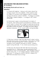
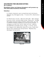
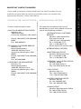
SCHWINN RETAIL BIKE
Service Manual
This manual applies to the following models:
101 102
103 112 113
122 123 126
130 131
201 202 203 206
212 213
223 226
230
PN 001-7082 rev B (03/07)
SERVICE MANUAL
CONTENTS
Table of Contents
Troubleshooting .................................................................2
Important Contact Numbers ..............................................11
TROUBLESHOOTING
Basic Troubleshooting
1. Problem:
No display/partial display/unit will not turn on
Solution:
A. Make sure unit is plugged into a functioning wall
outlet.
B. Check power connection at front (recumbent) or rear
(upright) of the unit. Connection should be secure and
undamaged. Replace adapter or connection at unit if
either are damaged.
C. Check data cable integrity. All wires in cable should
be intact. If any are visibly crimped or cut, replace
cable.
D. Check data cable connections/orientation. Insure
cable is connected securely and oriented properly.
Small latch on connector should line up and snap into
place.
E. Check console display for damage. Check for visual
sign that console display is cracked or otherwise
damaged. Replace console if damaged.
F. Check console display. If console only has partial
display and all connections are OK, replace computer.
Advanced Troubleshooting
If above steps do not resolve proceed to advanced
troubleshooting, problem A1.
2. Problem:
Unit operates but Contact HR not displayed
Solution:
Note: Sensors may have difficulty with dried out or
calloused hands. A conductive electrode cream such as
“Signa Crème” or “Buh-Bump” can help make better
conduct. These are available on the web or at medical
or some larger fitness stores.
A. Ensure hands are centered on HR sensors. Hands
must be kept still with relatively equal pressure applied
to each side.
B. Check HR cable connection at console. Ensure cable
is connected securely to console.
C. Check HR cable box connection. Ensure cables
from handlebars and cable to console are secure and
undamaged. Some models may require seat back be
raised to access cable box.
If the above tests reveal no problems, replace
the handlebars.
TROUBLESHOOTING
Basic Troubleshooting
TROUBLESHOOTING
Basic Troubleshooting
3. Problem:
Unit operates but Telemetric (if equipped) HR not displayed
Solution:
A. Verify you are working with a model that features
telemetric HR. Most models do not have this feature.
B. Check chest strap. Strap should be “Polar”
compatible. Make sure strap is directly against skin and
contact area is moist.
C. Check for interference. Try moving unit away from
sources of interference (TV, Microwave, etc.). If
interference is eliminated and HR still does not function,
replace strap and console.
4. Problem:
Console displays “E2” error code
Solution:
A. Check data cable integrity. All wires in cable should
be intact. If any are crimped or cut, replace cable.
B. Check data cable connections/orientation. Insure
cable is connected securely and oriented properly.
Small latch on connector should line up and snap into
place.
If the above tests reveal no problems, replace
the DC Motor.
TROUBLESHOOTING
Basic Troubleshooting
5. Problem:
No speed/RPM reading
Solution:
A. Check data cable integrity. All wires in cable should
be intact. If any are crimped or cut, replace cable.
B. Check data cable connections/orientation. Ensure
cable is connected securely and oriented properly.
Small latch on connector should line up and snap into
place.
C. Check magnet position (requires shroud removal).
Magnet should be in place on flywheel. If no magnet
present, replace flywheel or entire base unit if customer
unable to replace flywheel.
D. Check RPM Sensor (requires shroud removal). RPM
sensor should be aligned with magnet and connected
to data cable. Re-align sensor if necessary; replace if
any damage to sensor or connecting wire.
TROUBLESHOOTING
Basic Troubleshooting
6. Problem:
Console shuts off (enters sleep mode) while in use
Solution:
A. Check data cable integrity. All wires in cable should
be intact. If any are crimped or cut, replace cable.
B. Check data cable connections/orientation. Insure
cable is connected securely and oriented properly.
Small latch on connector should line up and snap into
place.
C. Reset Machine (if equipped with reset button).
Unplug unit from electrical outlet for 3 minutes.
Reconnect to outlet and after console powers up press
“reset”.
D. Check magnet position (requires shroud removal).
Magnet should be in place on flywheel. If no magnet
present, replace flywheel or entire base unit.
E. Check RPM Sensor (requires shroud removal). RPM
sensor should be aligned with magnet and connected
to data cable. Re-align sensor if necessary, replace if
any damage to sensor or connecting wire.
TROUBLESHOOTING
Basic Troubleshooting
7. Problem:
Unit rocks/does not sit level
Solution:
A. Check leveler adjustment. Leveling feet may be
turned in or out to level bike.
B. Check surface under unit. Adjustment may not be
able to compensate for extremely uneven surfaces.
Move bike to level area.
8. Problem:
Pedals loose/unit difficult to pedal
Solution:
A. Check pedal to crank connection. Pedal should be
tightened securely to crank. Insure connection is not
cross-threaded.
B. Check crank to axle connection. Crank should
be tightened securely to axle. Be sure cranks are
connected at 180 degrees from each other.
9. Problem:
Seat post feels loose
Solution:
A. Insure adjustment pin is locked into one of the seat
post adjustment holes.
B. Insure knob is securely tightened.
TROUBLESHOOTING
advanced Troubleshooting
A1. Problem:
No display/Unit will not turn on
Solution:
A. Check A/C adapter. Using a volt meter check the
voltage output from the adapter. With positive lead
on inside of connector and negative lead on outside,
voltage should be within 9-14VDC. If voltage is outside
this range, replace adapter. If voltage is OK, check
computer.
B. Disconnect upper wiring harness from back of
computer, and while power is supplied to machine, use
a volt meter to check that voltage is reaching computer.
Voltage between pins 1 (purple) and 3 (pink), (Figure A),
should be within 9-14VDC. If voltage is within range,
replace computer. If not, check upper wiring harness.
Figure A
C. Remove console mast and disconnect upper wiring
harness from lower wiring harness. Test output voltage
at lower harness using pins 1 and 3, as above. If
voltage is now present between 9-14VDC, replace
upper wiring harness. If not, check power plug wire.
D. Remove the shroud half that has the power plug
mounted into it. Disconnect power plug wire from
resistance motor wiring harness. Test voltage output of
power plug wire. If no voltage present, replace power
plug wire. If voltage is within 9-14VDC, replace DC
MOTOR (includes lower wiring).
A2. Problem:
Resistance does not change (assumes unit powers up
and otherwise functions normally)
Solution:
A. Check computer wire connections and continuity.
Replace any damaged wires. If wire is OK, check servo
motor.
B. Check servo motor. Remove shrouds. Test voltage
at servo motor red and black wires, (Figure B). Voltage
should be approximately 2.5VDC while either the UP
or DOWN console resistance buttons are pressed. If
voltage is correct but motor does not turn, replace
DC MOTOR (includes lower wiring). If motor turns
but magnet arm assembly does not move, check and
secure the mechanical components. Replace any
damaged components.
Figure B
TROUBLESHOOTING
advanced Troubleshooting
TROUBLESHOOTING
advanced Troubleshooting
A3. Problem:
Drive train click/tick noise once per full crank revolution
Solution:
A. Check bottom bracket. Remove pedals and rotate
crank. If sound persists, replace bottom bracket. If
sound is eliminated, check pedals.
B. Check pedals. Replace pedals and make sure they
are tightened securely. Rotate crank. If sound persists,
replace pedals.
A4. Problem:
Noise multiple times per revolution or once per 1.5 revolution.
Solution:
A. Check belt. Remove shrouds. Visually inspect belt
for irregularity while slowly rotating pedals. Replace if
damaged.
B. Check tensioner spring, pulley. Check the belt
tensioner spring is in place and functional. If tensioner
is in place but is not providing enough tension to
prevent belt from slipping, replace tension spring,
(Figure C).
C. Check flywheel hub.
Slowly rotate crank arms and
listen closely for sound from
flywheel hub. If sound is present,
replace the flywheel.
Figure C
10
If you need assistance, please have both the serial number of your
machine and the date of purchase available when you contact the
appropriate Nautilus office listed below.
OFFICES IN THE UNITED STATES:
E-mail: [email protected]
• NAUTILUS INNOVATION CENTER
Nautilus, Inc.
1886 Prairie Way
Louisville, Colorado, USA 80027
INTERNATIONAL OFFICES:
For technical assistance and a list of
distributors in your area, please call or fax
one of the following numbers.
• INTERNATIONAL CUSTOMER
SERVICE:
Nautilus International S.A.
Rue Jean Prouvé 6
1762 Givisiez / Switzerland
Tel: + 41-26-460-77-77
Fax: + 41-26-460-77-70
Email: [email protected]
Phone: 800-NAUTILUS (800-6288458)
Fax: 800-898-9410
• TECHNICAL/CUSTOMER SERVICE
Nautilus, Inc.
World Headquarters
16400 SE Nautilus Drive
Vancouver, Washington, USA
98683
Phone: 800-NAUTILUS (800-6288458)
Fax: 877-686-6466
• CORPORATE HEADQUARTERS
Nautilus, Inc.
World Headquarters
16400 SE Nautilus Drive
Vancouver, Washington, USA
98683
Phone: 800-NAUTILUS (800-6288458)
INTERNATIONAL OFFICES:
• SWITZERLAND OFFICE
Nautilus Switzerland S.A.
Tel: + 41-26-460-77-66
Fax: + 41-26-460-77-60
• GERMANY and AUSTRIA OFFICE
Nautilus GmbH
Tel: +49 2203/20 20-0
Fax: +49 2203/20 20-45 45
• ITALY OFFICE
Nautilus Italy s.r.l.
Tel: +39-051-664-6201
Fax: +39-051-664-7461
• UNITED KINGDOM OFFICE
Nautilus UK Ltd.
Tel: +44-1908-267-345
Fax: +44-1908-267-346
• CHINA OFFICE
Nautilus Representative Office
Tel: +86-21-523-707-00
Fax: +86-21-523-707-09
11
IMPORTANT CONTACT NUMBERS
IMPORTANT CONTACT NUMBERS