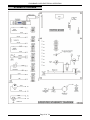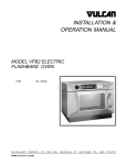
1
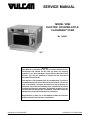
SERVICE MANUAL
MODEL VFB2
ELECTRIC COUNTER-STYLE
FLASHBAKE® OVEN
ML 126582
- NOTICE This Manual is prepared for the use of trained Vulcan Service
Technicians and should not be used by those not properly
qualified. If you have attended a Vulcan Service School for this
product, you may be qualified to perform all the procedures
described in this manual.
This manual is not intended to be all encompassing. If you have
not attended a Vulcan Service School for this product, you should
read, in its entirety, the repair procedure you wish to perform to
determine if you have the necessary tools, instruments and skills
required to perform the procedure. Procedures for which you do
not have the necessary tools, instruments and skills should be
performed by a trained Vulcan Service Technician.
Reproduction or other use of this Manual, without the express
written consent of Vulcan-Hart, is prohibited.
A product of VULCAN-HART
Form 24674 (March 2000)
LOUISVILLE, KY 40201-0696
FLASHBAKE® OVEN GENERAL
TABLE OF CONTENTS
GENERAL . . . . . . . . . . . . . . . . . . . . . . . . . . . . . . . . . . . . . . . . . . . . . . . . . . . . . . . . . . . . . . . . . . . . . . . . . . . . .
Introduction . . . . . . . . . . . . . . . . . . . . . . . . . . . . . . . . . . . . . . . . . . . . . . . . . . . . . . . . . . . . . . . . . . . . . . . .
Electrical Specifications . . . . . . . . . . . . . . . . . . . . . . . . . . . . . . . . . . . . . . . . . . . . . . . . . . . . . . . . . . . . . . .
Installation . . . . . . . . . . . . . . . . . . . . . . . . . . . . . . . . . . . . . . . . . . . . . . . . . . . . . . . . . . . . . . . . . . . . . . . . .
Operation . . . . . . . . . . . . . . . . . . . . . . . . . . . . . . . . . . . . . . . . . . . . . . . . . . . . . . . . . . . . . . . . . . . . . . . . . .
Cleaning . . . . . . . . . . . . . . . . . . . . . . . . . . . . . . . . . . . . . . . . . . . . . . . . . . . . . . . . . . . . . . . . . . . . . . . . . .
Tools . . . . . . . . . . . . . . . . . . . . . . . . . . . . . . . . . . . . . . . . . . . . . . . . . . . . . . . . . . . . . . . . . . . . . . . . . . . . .
3
3
3
3
3
3
3
REMOVAL AND REPLACEMENT OF PARTS . . . . . . . . . . . . . . . . . . . . . . . . . . . . . . . . . . . . . . . . . . . . . . . . . 4
Covers and Panels . . . . . . . . . . . . . . . . . . . . . . . . . . . . . . . . . . . . . . . . . . . . . . . . . . . . . . . . . . . . . . . . . . . 4
Main Cover . . . . . . . . . . . . . . . . . . . . . . . . . . . . . . . . . . . . . . . . . . . . . . . . . . . . . . . . . . . . . . . . . . . . . 4
Control Panel . . . . . . . . . . . . . . . . . . . . . . . . . . . . . . . . . . . . . . . . . . . . . . . . . . . . . . . . . . . . . . . . . . . 4
Fan . . . . . . . . . . . . . . . . . . . . . . . . . . . . . . . . . . . . . . . . . . . . . . . . . . . . . . . . . . . . . . . . . . . . . . . . . . . . . . 5
Door . . . . . . . . . . . . . . . . . . . . . . . . . . . . . . . . . . . . . . . . . . . . . . . . . . . . . . . . . . . . . . . . . . . . . . . . . . . . . . 5
Display, Keypad Assembly . . . . . . . . . . . . . . . . . . . . . . . . . . . . . . . . . . . . . . . . . . . . . . . . . . . . . . . . . . . . . 6
Control Board . . . . . . . . . . . . . . . . . . . . . . . . . . . . . . . . . . . . . . . . . . . . . . . . . . . . . . . . . . . . . . . . . . . . . . . 6
Control Board Proms . . . . . . . . . . . . . . . . . . . . . . . . . . . . . . . . . . . . . . . . . . . . . . . . . . . . . . . . . . . . . . . . . 7
Upper Lamp Housing Assembly . . . . . . . . . . . . . . . . . . . . . . . . . . . . . . . . . . . . . . . . . . . . . . . . . . . . . . . . . 7
Lamps (Upper) . . . . . . . . . . . . . . . . . . . . . . . . . . . . . . . . . . . . . . . . . . . . . . . . . . . . . . . . . . . . . . . . . . 8
Exhaust Ducts, Thermistor . . . . . . . . . . . . . . . . . . . . . . . . . . . . . . . . . . . . . . . . . . . . . . . . . . . . . . . . . 9
Lamp Reflector (Upper) . . . . . . . . . . . . . . . . . . . . . . . . . . . . . . . . . . . . . . . . . . . . . . . . . . . . . . . . . . . 9
Center Post and/or Thermostat (Upper) . . . . . . . . . . . . . . . . . . . . . . . . . . . . . . . . . . . . . . . . . . . . . . 10
Lamp Socket (Upper) . . . . . . . . . . . . . . . . . . . . . . . . . . . . . . . . . . . . . . . . . . . . . . . . . . . . . . . . . . . . 10
Lower Lamp Housing Assembly . . . . . . . . . . . . . . . . . . . . . . . . . . . . . . . . . . . . . . . . . . . . . . . . . . . . . . . . 10
Lamps (Lower) . . . . . . . . . . . . . . . . . . . . . . . . . . . . . . . . . . . . . . . . . . . . . . . . . . . . . . . . . . . . . . . . . 12
Lamp Reflector (Lower) . . . . . . . . . . . . . . . . . . . . . . . . . . . . . . . . . . . . . . . . . . . . . . . . . . . . . . . . . . 12
Center Post, Pan Sensor and/or Thermostat (Lower) . . . . . . . . . . . . . . . . . . . . . . . . . . . . . . . . . . . . 13
Lamp Socket (Lower) . . . . . . . . . . . . . . . . . . . . . . . . . . . . . . . . . . . . . . . . . . . . . . . . . . . . . . . . . . . . 13
Door Latch Assembly . . . . . . . . . . . . . . . . . . . . . . . . . . . . . . . . . . . . . . . . . . . . . . . . . . . . . . . . . . . . . . . . 14
SERVICE PROCEDURES AND ADJUSTMENTS . . . . . . . . . . . . . . . . . . . . . . . . . . . . . . . . . . . . . . . . . . . . . .
Door Switch . . . . . . . . . . . . . . . . . . . . . . . . . . . . . . . . . . . . . . . . . . . . . . . . . . . . . . . . . . . . . . . . . . . . . . .
Thermistor Test . . . . . . . . . . . . . . . . . . . . . . . . . . . . . . . . . . . . . . . . . . . . . . . . . . . . . . . . . . . . . . . . . . . .
Prom Version . . . . . . . . . . . . . . . . . . . . . . . . . . . . . . . . . . . . . . . . . . . . . . . . . . . . . . . . . . . . . . . . . . . . . .
Service Diagnostics . . . . . . . . . . . . . . . . . . . . . . . . . . . . . . . . . . . . . . . . . . . . . . . . . . . . . . . . . . . . . . . . .
Pan Sensor Calibration . . . . . . . . . . . . . . . . . . . . . . . . . . . . . . . . . . . . . . . . . . . . . . . . . . . . . . . . . . . . . .
Memory Check . . . . . . . . . . . . . . . . . . . . . . . . . . . . . . . . . . . . . . . . . . . . . . . . . . . . . . . . . . . . . . . . . . . . .
15
15
15
15
16
16
17
ELECTRICAL OPERATION . . . . . . . . . . . . . . . . . . . . . . . . . . . . . . . . . . . . . . . . . . . . . . . . . . . . . . . . . . . . . .
Component Function . . . . . . . . . . . . . . . . . . . . . . . . . . . . . . . . . . . . . . . . . . . . . . . . . . . . . . . . . . . . . . . .
Component Location . . . . . . . . . . . . . . . . . . . . . . . . . . . . . . . . . . . . . . . . . . . . . . . . . . . . . . . . . . . . . . . .
Control Board Layout . . . . . . . . . . . . . . . . . . . . . . . . . . . . . . . . . . . . . . . . . . . . . . . . . . . . . . . . . . . . . . . .
Schematic Diagram . . . . . . . . . . . . . . . . . . . . . . . . . . . . . . . . . . . . . . . . . . . . . . . . . . . . . . . . . . . . . . . . .
Wiring Diagram . . . . . . . . . . . . . . . . . . . . . . . . . . . . . . . . . . . . . . . . . . . . . . . . . . . . . . . . . . . . . . . . . . . .
Sequence of Operation . . . . . . . . . . . . . . . . . . . . . . . . . . . . . . . . . . . . . . . . . . . . . . . . . . . . . . . . . . . . . .
18
18
19
20
21
22
23
TROUBLESHOOTING . . . . . . . . . . . . . . . . . . . . . . . . . . . . . . . . . . . . . . . . . . . . . . . . . . . . . . . . . . . . . . . . . . 24
© VULCAN 2000
Page 2 of 24
FLASHBAKE® OVEN GENERAL
GENERAL
INTRODUCTION
OPERATION
General
®
The FlashBake oven is a versatile oven that
employs a revolutionary high quality, high speed
cooking technology. The baking process is so fast
that food retains its natural juices. Bread products
brown and become crisp while vegetables retain
their color and texture. The texture, appearance and
quality of food cooked in this oven is superior to that
provided by any other method of cooking.
In conventional ovens, the cooking process occurs
by transferring heat energy from the air inside the
oven into the food. Hot surfaces inside the oven
also transfer heat directly into the food by
conduction. In convection ovens, the air-to-food
heat transfer is enhanced by the uniform circulation
of the heated air around the food. Forced air ovens
blow the heated air directly onto the food, providing
marginal increases in cooking speeds.
Refer to the INSTALLATION AND OPERATION
MANUAL shipped with the oven for complete
operating instructions, precautions and utensils to
use.
CLEANING
CAUTION: Never use oven cleaners to clean the
oven. Never use abrasives or sharp objects on
the oven walls or window.
Refer to the INSTALLATION AND OPERATION
MANUAL shipped with the oven for complete
cleaning instructions.
TOOLS
®
FlashBake ovens use visible and infrared light
energy to cook by radiative heat transfer. The
infrared energy browns the surface of the food,
while the visible light energy penetrates and heats it
internally. Using the proper combination of visible
and infrared light energy, the FlashBake® oven
provides efficient, high-speed baking and highquality food.
Eight 1,000 watt quartz halogen lamps, four on top
and four on the bottom, cycle in a circular motion to
promote even browning.
Oven has a pan sensor in the bottom of oven cavity
which reads pan reflectivity and automatically
adjusts halogen lamps to achieve optimal cooking
results.
•
Standard set of hand tools
•
VOM with AC current tester (Any VOM with a
sensitivity of at least 20,000 ohms per volt)
Special Tools
•
RTV #732 Part #513886
•
Blue Shower ll cleaner Part #547240
•
Jumper Plug Part # 252289
•
Pin Extraction Tool for MOLEX® MINI-FIT
JR.™ Connectors
ELECTRICAL SPECIFICATIONS
120 volt, 60 Hz, single phase, 15 amp power supply
with cord and plug.
INSTALLATION
Refer to the INSTALLATION AND OPERATION
MANUAL shipped with the oven for installation
instructions.
Page 3 of 24
FLASHBAKE® OVEN REMOVAL AND REPLACEMENT OF PARTS
REMOVAL AND REPLACEMENT OF PARTS
CAUTION: Handle all reflective parts and interior door glass carefully to prevent scratching or marking of
surfaces.
Control Panel
COVERS AND PANELS
1.
Remove “MAIN COVER”.
WARNING: UNPLUG THE MAIN POWER CORD.
2.
Unplug ribbon cable from rear of panel.
Main Cover
3.
Remove screws securing panel from rear.
4.
Reverse procedure to install.
1.
Remove screws securing cover at rear of unit.
NOTE: When reconnecting ribbon cable, be sure to
line up arrowheads as shown in picture. They
designate pin 1. The red trace on the cable also
designates pin 1.
2.
Remove one screw securing each side of cover
located underneath side of unit.
3.
Slide cover rearward to disengage cover from
front top and front sides of unit.
4.
Carefully lift cover off unit.
5.
Reverse procedure to install.
Page 4 of 24
FLASHBAKE® OVEN REMOVAL AND REPLACEMENT OF PARTS
FAN
DOOR
WARNING: UNPLUG THE MAIN POWER CORD.
WARNING: UNPLUG THE MAIN POWER CORD.
1.
Remove “MAIN COVER”.
1.
2.
Disconnect wires from fan.
Remove four screws securing outer door
assembly and remove outer half.
2.
To replace door handle, door latch or outer
door window and window gasket:
3.
Remove screws securing fan and guard.
4.
Remove fan and guard.
5.
Reverse procedure to install.
A.
Remove two bolts securing door handle.
3.
Remove inner door assembly by swinging to
the open position and lifting off hinge.
4.
To remove inner door window and window
gasket:
A.
Page 5 of 24
Remove three screws securing lower
window bracket and remove bracket.
FLASHBAKE® OVEN REMOVAL AND REPLACEMENT OF PARTS
B.
Slide window and gasket out of door.
CONTROL BOARD
WARNING: UNPLUG THE MAIN POWER CORD.
CAUTION: Certain components in this system
are subject to damage by electrostatic discharge
during field repairs. a field service grounding kit
is available to prevent damage. The field service
grounding kit must be used anytime the control
board is handled.
5.
Reverse procedure to install.
1.
Remove “MAIN COVER”.
2.
Identify and disconnect all wires and plugs from
control board.
3.
Remove nuts and washers securing board to
standoffs.
4.
Squeeze tabs on standoffs and push standoffs
through back panel. Support control board so
that it does drop and remove control board.
DISPLAY, KEYPAD ASSEMBLY
WARNING: UNPLUG THE MAIN POWER CORD.
CAUTION: Certain components in this system
are subject to damage by electrostatic discharge
during field repairs. A field service grounding kit
is available to prevent damage. The field service
grounding kit must be used anytime the control
board is handled.
1.
Remove “MAIN COVER”.
2.
Remove “CONTROL PANEL”.
3.
Pull off rotary switch knob.
4.
Remove screws securing lower circuit board
bracket and remove bracket.
5.
Carefully work circuit board assembly out of
panel.
6.
Reverse procedure to install.
Page 6 of 24
FLASHBAKE® OVEN REMOVAL AND REPLACEMENT OF PARTS
5.
Squeeze tabs on standoffs and push standoffs
out of control board.
3.
Insert new prom being sure orientation is
correct. Insure that pins do not get bent.
4.
Install main cover.
UPPER LAMP HOUSING
ASSEMBLY
6.
NOTE: When upper lamp housing is removed for
any reason, inspect lamp sockets and center post
contact plate for pitting due to bad connections and
replace parts as required.
Reverse procedure to install.
WARNING: UNPLUG THE MAIN POWER CORD.
CONTROL BOARD PROMS
WARNING: UNPLUG THE MAIN POWER CORD.
CAUTION: Certain components in this system
are subject to damage by electrostatic discharge
during field repairs. a field service grounding kit
is available to prevent damage. The field service
grounding kit must be used anytime the control
board is handled.
Parts that can be accessed when upper housing is
removed:
•
ring reflector and gasket
•
glass and gasket
•
lamps and lamp sockets
•
center post with lamp contact plate
•
lamp reflector
1.
Remove “MAIN COVER”.
•
thermostat
2.
Note prom orientation, then carefully remove
prom by prying out of socket.
1.
Remove “MAIN COVER”.
2.
Remove “CONTROL PANEL”.
3.
Remove “DOOR”.
4.
Disconnect wires and plugs that connect upper
housing assembly to control board.
5.
Remove screws securing upper housing
bracket.
NOTE: Look for a notch or other identifying mark
that indicates the prom end with pin1.
Page 7 of 24
FLASHBAKE® OVEN REMOVAL AND REPLACEMENT OF PARTS
6.
Remove 4 screws securing upper housing
assembly to reflective cylinder.
7.
Remove nuts on both upper housing eye bolts
and remove eye bolts.
9.
NOTE: On reassembly, tighten nuts on eye bolts to
approximately 3/4" exposed threads.
8.
Loosen two nuts securing both reflective
cylinder cinch plates.
Lift rear of housing assembly out of reflective
cylinder and then carefully work the rest of the
housing out of the cylinder.
10. Reverse procedure to install.
Lamps (Upper)
1.
Remove “UPPER LAMP HOUSING
ASSEMBLY”.
2.
Remove 7 screws securing reflector ring to
upper housing.
3.
Remove reflector ring and ring gasket. Watch
for shoulder washers under ring.
NOTE: When reassembling, shoulder on washer
goes into screw hole in ring from bottom side of ring.
4.
Page 8 of 24
Lift out glass with glass gasket.
FLASHBAKE® OVEN REMOVAL AND REPLACEMENT OF PARTS
5.
Remove lamps by pushing lamps away from
center post to disengage them from center post
and then lift out of housing.
CAUTION: Use clean dry cloth to handle lamps.
DO NOT get finger prints or any other residue
on lamps because the lamp life will be
shortened. Clean cold lamps with a cloth
moistened with alcohol cleaner to remove skin
oil or other residue.
4.
Reverse procedure to install.
Lamp Reflector (Upper)
1.
Remove “LAMPS”.
2.
Remove “EXHAUST DUCTS”.
3.
Straighten 4 tabs (1 in each air passage)
securing lamp reflector to housing.
4.
Straighten 4 sets of reflector tabs securing
reflector thru housing slots.
NOTE: When installing lamps, nub on lamp should
be on either side of lamp, not on top or bottom of
lamp.
6.
Reverse procedure to install.
Exhaust Ducts, Thermistor
1.
Remove “MAIN COVER”.
2.
Remove exhaust ducts by releasing tab in slot.
Press from inside duct in an outward direction
to disengage tab and pull out of slot.
3.
To change thermistor, remove thermistor wires
from duct by sliding wires out of slit in duct.
Extract thermistor pins out of J2 with pin
extraction tool.
Page 9 of 24
FLASHBAKE® OVEN REMOVAL AND REPLACEMENT OF PARTS
5.
Carefully work reflector out by lifting outer
edges to enable center of reflector to separate
and come out from under washer on center
post.
6.
Reverse procedure to install. Be sure reflector
is under washer on center post before reflector
tabs are bent. If not under washer, there will not
be sufficient clearance to insert lamps into
lamp socket.
7.
Clean reflector with a cloth moistened with Blue
Shower cleaner to remove skin oil or other
residue. Buff dry with clean dry cloth to remove
any smears.
Center Post and/or Thermostat (Upper)
Lamp Socket (Upper)
1.
Remove “LAMPS”.
2.
Disconnect wire from lamp socket being
removed.
3.
Remove screw securing lamp socket and
remove socket.
4.
Reverse procedure to install. Do not over
tighten lamp socket mounting screws.
LOWER LAMP HOUSING
ASSEMBLY
NOTE: When lower lamp housing is removed for
any reason, inspect lamp sockets and center post
contact plate for pitting due to bad connections and
replace parts as required.
1.
Remove “LAMP REFLECTOR”.
2.
Disconnect wire and remove screws securing
center post assembly.
WARNING: UNPLUG THE MAIN POWER CORD.
3.
Disconnect wires from thermostat and remove
screw securing thermostat.
Parts that can be accessed when lower housing is
removed:
4.
•
reflector ring
•
glass and glass/apron gasket
•
lamps and lamp sockets
•
center post with lamp contact plate and pan
sensor
•
lamp reflector
•
thermostat
1.
Remove “UPPER LAMP HOUSING
ASSEMBLY”.
Reverse procedure to install. Do not over
tighten center post screws.
Page 10 of 24
FLASHBAKE® OVEN REMOVAL AND REPLACEMENT OF PARTS
2.
Remove 1 screw on each side and remove air
deflector.
3.
Loosen 1 screw each side securing reflective
cylinder to lower lamp housing.
4.
Remove nut on eye hook on each side.
5.
Remove “DOOR LATCH”.
6.
Remove 2 reflective cylinder cinch plate nuts
on each side.
10. Remove 2 nuts and washers securing lower
housing bracket to base of unit.
11. Disconnect lower lamp housing wires and plugs
from control board.
12. Lift lower lamp housing assembly out of unit.
13. Reverse procedure to install components
leaving mounting screws and nuts loose.
A.
Tighten nuts on eye bolts to draw
reflective cylinder snug around upper and
lower housing assemblies. Tighten nuts
until there is approximately 3/4" of
exposed threads on eye bolts.
7.
Remove screws loosened in step 3 and
carefully lift out reflective cylinder.
8.
Remove screws securing apron and carefully
withdraw apron from gasket.
B.
Tighten screws securing air deflector and
cylinder to upper and lower housings.
NOTE: If you tilt unit back to access screws, use a
block to support back of unit to prevent damaging
power cord strain relief.
C.
Manually push housing/cylinder assembly
to front of unit and hold there while
tightening cylinder cinch plate nuts.
D.
Tighten screws on upper housing
mounting bracket.
E.
Tighten nuts and washers securing lower
housing bracket to base of unit.
9.
Lift out glass with gasket.
NOTE: If gasket is to be replaced, remove it from
glass and clean off any gasket material that may be
stuck to glass. Use RTV 732 around edge of glass to
seal new gasket to glass.
Page 11 of 24
FLASHBAKE® OVEN REMOVAL AND REPLACEMENT OF PARTS
Lamps (Lower)
1.
Perform removal procedure “LOWER LAMP
HOUSING ASSEMBLY” steps 1 thru 9.
2.
Remove lamps by pushing lamps away from
center post to disengage them from center post
and then lift out of housing.
4.
Remove exhaust ducts by releasing tab in slot.
Press from inside duct in an outward direction
to disengage tab and pull out of slot.
5.
Straighten 4 tabs (1 in each air passage)
securing lamp reflector to housing.
6.
Straighten 4 sets of reflector tabs securing
reflector thru housing slots.
CAUTION: Use clean dry cloth to handle lamps.
DO NOT get finger prints or any other residue
on lamps because the lamp life will be
shortened. Clean cold lamps with a cloth
moistened with alcohol cleaner to remove skin
oil or other residue.
NOTE: When installing lamps, nub on lamp should
be on either side of lamp, not on top or bottom of
lamp.
3.
Reverse procedure to install.
Lamp Reflector (Lower)
1.
Remove “LAMPS”.
2.
Perform remaining removal steps in “LOWER
LAMP HOUSING ASSEMBLY”.
3.
Lift out reflector ring.
Page 12 of 24
FLASHBAKE® OVEN REMOVAL AND REPLACEMENT OF PARTS
7.
Carefully work reflector out by lifting outer
edges to enable center of reflector to separate
and come out from under washer on center
post.
8.
Reverse procedure to install. Be sure reflector
is under washer on center post before reflector
tabs are bent. If not under washer, there will not
be sufficient clearance to insert lamps into
lamp socket.
9.
Clean reflector with a cloth moistened with Blue
Shower cleaner to remove skin oil or other
residue. Buff dry with clean dry cloth to remove
any smears.
3.
Disconnect wires from thermostat and remove
screw securing thermostat.
4.
Reverse procedure to install. Do not over
tighten center post mounting screws.
Lamp Socket (Lower)
1.
Remove “LAMPS”.
2.
Perform remaining removal steps in “LOWER
LAMP HOUSING ASSEMBLY”.
3.
Disconnect wire from socket being replaced.
4.
Remove screw securing lamp socket and
remove socket.
5.
Reverse procedure to install. Do not over
tighten lamp socket mounting screws.
Center Post, Pan Sensor and/or Thermostat
(Lower)
1.
Remove “LAMP REFLECTOR”.
2.
Disconnect wire from center post and remove
screws securing center post with pan sensor.
A.
Cut wire ties to release pan sensor wires.
B.
Extract sensor pins out of J3 with pin
extraction tool.
NOTE: Orientation of pan sensor is curve side
to the inside of center post.
Page 13 of 24
FLASHBAKE® OVEN REMOVAL AND REPLACEMENT OF PARTS
12. Press door bumper tabs into cutouts in latch
assembly.
DOOR LATCH ASSEMBLY
WARNING: UNPLUG THE MAIN POWER CORD.
1.
Remove “MAIN HOUSING”.
2.
Remove top nuts and loosen bottom nuts
securing latch assembly to unit.
3.
Pull latch assembly rearward to release door
bumper and lift assembly off lower mounting
studs.
4.
To change solenoid, remove screws securing it.
5.
Cut wire tie and disconnect wires from harness.
6.
Remove screws securing switch.
7.
Disconnect wires from switch.
8.
Adjust switch as outlined in “DOOR SWITCH”.
9.
Reverse procedure to install.
10. Adjust assembly up or down to align with door
striker.
11. Tighten latch assembly mounting nuts.
Page 14 of 24
FLASHBAKE® OVEN SERVICE PROCEDURES AND ADJUSTMENTS
SERVICE PROCEDURES AND ADJUSTMENTS
DOOR SWITCH
WARNING: UNPLUG THE MAIN POWER CORD.
When in a cook cycle, the door switch should not
operate before the latch pawl contacts the energized
solenoid pawl lock.
1.
Perform steps 1 thru 3 in removal procedure
“DOOR LATCH ASSEMBLY”.
NOTE: Picture below shows latch pawl in the open
door position.
2.
Manually move latch pawl to “door closed
position”. Switch is operated.
3.
Manually press solenoid pawl lock into the
energized position and hold it there.
4.
5.
Manually move latch pawl to the open door
position.
6.
Reverse procedure to install.
7.
Perform steps 10 thru 12 in removal procedure
“DOOR LATCH ASSEMBLY”.
THERMISTOR TEST
WARNING: UNPLUG THE MAIN POWER CORD.
Manually move latch pawl towards open
position until latch pawl contacts solenoid pawl
lock. Switch should NOT unoperate. If
adjustment is needed, reform switch operating
lever.
1.
Unplug J2 from control board.
2.
Attach ohm meter leads to thermistor wires.
A.
NOTE: Switch may be tested in service diagnostics.
Reading should be approximately 125.5K
ohms ± 10% at room temperature(70(F).
PROM VERSION
To display installed prom version, unplug power
cord from receptacle and wait a few seconds. Plug
in power cord and watch display. It will momentarily
display version of installed prom. Example
(CML3.09)
Page 15 of 24
FLASHBAKE® OVEN SERVICE PROCEDURES AND ADJUSTMENTS
SERVICE DIAGNOSTICS
a.
The display will report the values
at the end of a 7 second test.
Values reported for REFL, VOLT
and TEMP should be between
zero and 255. Values should not
be zero or 255.
b.
Ignore the values on the right
side of the display.
To enter service diagnostics:
1.
Remove “MAIN HOUSING”.
2.
Unplug power cord.
3.
Install jumper on JP103 on control board.
4.
Set selector knob to Brown.
5.
Plug unit in.
6.
Rotate knob to Grill.
Listen for two beeper tones.
A.
Press Stop.
B.
Press any key and verify all display
segments work.
B.
C.
Verify that blue display backlight is on.
Rotate the knob to each position and
verify the display matches each knob
position.
C.
Press each key (there are 14) and verify
correct key is displayed.
Rotate knob to Bake.
Open and close door.
1)
NOTE: The Stop key must be pressed last.
Verify the sensor is working by
observing change on display.
a.
b.
8.
9.
Press Stop.
A.
A.
7.
2)
10. Unplug the unit.
Display should read “Door
CLOSED” when door is closed.
11. Remove jumper from JP103.
12. Install main housing.
Display should read “Door
OPEN” when door is open.
B.
Display reads “Thermostat CLOSED”.
C.
Display reads “Eyeball sees: DARK”.
PAN SENSOR CALIBRATION
Rotate knob to Preset.
NOTE: Oven must be clean and cooled down
before starting calibration test.
A.
Press Stop.
1.
Remove “MAIN HOUSING”.
B.
Press Start to start lamp test.
2.
Plug unit in.
1)
3.
Set time to 1:00.
4.
Set knob to Cook.
Rotate knob to Cook.
5.
Press Start.
A.
Press 1 to test the door lock.
6.
After 15 seconds, press Save.
1)
7.
Check the values reported on the display.
Verify that all eight lamps turn on and
off in sequence in a clockwise
rotation.
Press Start to toggle the door lock on
and off.
a.
2)
B.
Press Stop.
2)
B.
Press Start to toggle the fan on and
off.
a.
Verify that fan works and comes
up to full speed.
Press Stop.
Press 3 to test the pan sensor.
1)
Verify that the voltage value is between
215 and 231.
NOTE: If the voltage value is not correct,
check the input voltage. It should be 115VAC.
The value reported is NOT the real voltage, it is
a reading that represents the voltage the
control board is seeing.
Press 2 to test the fan.
1)
C.
Verify that lock works by
watching solenoid pawl lock
move to lock and unlock
positions.
A.
Press Start to begin the sensor test.
Page 16 of 24
If the voltage value is in the correct range,
check the REFL value.
1)
The REFL value should be between
95 and 100.
2)
Press Stop twice.
FLASHBAKE® OVEN SERVICE PROCEDURES AND ADJUSTMENTS
3)
If value is out of range, adjust R99 on
the control board. Turn clockwise to
increase the value, counterclockwise
to decrease the value.
NOTE: Readings do not change if you adjust R99
while watching display. The unit must go thru the 15
second test to display a new value. The
potentiometer is sensitive so only turn it about 1/8
turn or less at one time.
8.
Press Start.
9.
After 15 seconds, press Save.
10. Check the values reported on the display.
11. Press Stop twice.
12. Readjust R99 as required.
13. Repeat steps 8 thru 12 until readings are in
proper range.
14. Install main housing.
MEMORY CHECK
1.
Plug unit in.
2.
Set knob to Cook position.
3.
Set time to 1:00 minute.
4.
Press Save.
5.
Press the (1) key.
6.
Set time to 2:00 minutes.
7.
Press Save.
8.
Press the (2) key.
9.
Continue incrementing the time by one minute,
and save it to the next storage number until all
nine storage units are filled.
10. Set knob to the Preset position.
11. Press (1) key.
A.
The unit should start in Cook mode with
1:00 shown on display timer.
12. Press Stop two times.
13. Press the (2) key.
A.
The unit should start in Cook mode with
2:00 shown on display timer.
14. Press Stop two times.
15. Repeat with all nine storage locations. In each
case the unit should start with the appropriate
time shown.
Page 17 of 24
FLASHBAKE® OVEN ELECTRICAL OPERATION
ELECTRICAL OPERATION
COMPONENT FUNCTION
F1 FUSE . . . . . . . . . . . . . . . . . . . . . . . . .
Protects transformer and fan.
FAN . . . . . . . . . . . . . . . . . . . . . . . . . . . .
Moves air across lamps to help cool lamp area.
THERMOSTATS . . . . . . . . . . . . . . . . . .
Protects oven cavity from overheating. Monitors temperature in
upper lamp housing and in lower lamp housing. Opens at 200(F
(± 5); auto reset at 170(F (± 5).
DOOR SWITCH . . . . . . . . . . . . . . . . . . .
Prevents oven from operating with door open.
DOOR LOCK SOLENOID . . . . . . . . . . .
Locks door to prevent door from being opened when in a cook
cycle.
CONTROL BOARD . . . . . . . . . . . . . . . .
Contains software and other components used to operate the cook
cycles.
KEYPAD . . . . . . . . . . . . . . . . . . . . . . . . .
Allows information to be sent by operator to the control board.
DISPLAY . . . . . . . . . . . . . . . . . . . . . . . .
Displays information needed by the customer to operate the oven.
THERMISTOR . . . . . . . . . . . . . . . . . . . .
Signals the control board the temperature in the exhaust duct. The
control board then keeps the fan running as needed at the end of a
cook cycle to cool the lamps. Also provides information to adjust
cooking parameters based on oven temperature.
LAMP . . . . . . . . . . . . . . . . . . . . . . . . . . .
Supplies visible and infrared light used to cook the product.
PAN SENSOR . . . . . . . . . . . . . . . . . . . . .
Signals control board as to the type of pan being used and then the
control board adjusts accordingly.
Page 18 of 24
FLASHBAKE® OVEN ELECTRICAL OPERATION
COMPONENT LOCATION
Page 19 of 24
FLASHBAKE® OVEN ELECTRICAL OPERATION
CONTROL BOARD LAYOUT
Page 20 of 24
FLASHBAKE® OVEN ELECTRICAL OPERATION
SCHEMATIC DIAGRAM
Page 21 of 24
FLASHBAKE® OVEN ELECTRICAL OPERATION
WIRING DIAGRAM
Page 22 of 24
FLASHBAKE® OVEN ELECTRICAL OPERATION
8.
SEQUENCE OF OPERATION
Oven reverts back to conditions in step 2.
Operation Monitor
1.
A.
Correct voltage to oven on control board.
B.
Power fuse good.
C.
Building Circuit breakers closed.
The unit uses the control board to monitor the status
of certain points on the oven. If the status of any
point is not within normal operating conditions a
message is reported and the relay on the control
board which powers the lamps may be deenergized.
D.
Thermostats closed.
1.
E.
Door switch closed.
F.
Product in oven.
Oven Door - The door must be closed before
cooking is allowed. If the door is not closed a
message will be displayed.
2.
Temperature - If the oven is too hot, cooking is
not allowed. A message is displayed and the
relay will be de-energized. Temperature is
monitored by two thermostats both of which
must be satisfied before the oven will cook.
Conditions
2.
Display is illuminated because power is applied
to control board.
3.
Cook cycle selected.
4.
Cycle time is entered.
5.
“START” key is pressed.
A.
LED (CR3) on control board is lit.
B.
Compartment fan energized.
C.
Door lock solenoid energized.
1)
D.
Lamp power is controlled by control board
depending on signals received from pan
sensor, thermistor and cooking controls.
1)
E.
6.
Lamps are energized.
Cook cycle timer counts down.
If Pause key is pressed, cook cycle stops.
(Pressing Start resumes cooking cycle).
A.
Lamps are de-energized.
B.
Door lock solenoid de-energized.
1)
7.
Door locked.
Door is unlocked.
C.
Beeper sounds.
D.
Compartment fan remains energized.
E.
Cook timer stops counting down.
If cook cycle times out or if Stop key is pressed
twice, (pressing once puts unit in pause mode)
cook cycle stops and resets cook cycle timer to
zero.
A.
Beeper sounds.
B.
Compartment fan runs as long as control
board senses a need to cool compartment
down. Can run up to a maximum of 4
minutes.
C.
LED (CR3) on control board is off.
D.
Lamps are de-energized.
E.
Door lock solenoid de-energized.
1)
Door is unlocked.
Page 23 of 24
FLASHBAKE® OVEN TROUBLESHOOTING
TROUBLESHOOTING
ERROR MESSAGES
MESSAGE
Oven can not operate. Oven is overheated.
Oven can not operate. Door is not closed.
SYMPTOM
Oven does not operate.
Oven does not enter a cook cycle and displays error
messages.
Fan continues to run after cook cycle is completed.
NOTE: It is normal for fan to run a while
(approximately 4 minutes maximum) after a cook
cycle ends to cool down lamp housings.
Fan never runs.
Display does not light up/no characters displayed.
You can open door while in a cook cycle.
Can not set cooking time or enter other keypad
information.
Door does not latch/close completely.
Won’t save recipe settings.
Beeper doesn’t work.
Cooking lights come on and stay on, they don’t
“rotate”.
Erratic operation of display or display locks up.
Form 24674 (March 2000)
ACTION
Check both upper and lower thermostat circuits.
If thermostat is opened, control board prevents
operation.
2. Check that fan is operational.
3. Check that there is sufficient clearance for air
circulation around unit.
Check door switch circuit.
1.
POSSIBLE CAUSES
1. Power cord.
2. Main circuit breaker open.
3. Fuse F1 on control board open.
4. Control board malfunction.
5. Ribbon cable.
6. Control panel circuit board.
Refer to Error Message chart.
1.
2.
Shorted or malfunctioning thermistor.
Thermistor not properly located inside upper
exhaust duct. It should hang freely in the center
of the duct.
3. Unit in Pause Mode.
4. Control board malfunction.
1. Fan malfunction.
2. Control board malfunction.
1. Ribbon cable.
2. Control panel circuit board malfunction.
3. Control board malfunction.
1. Latch solenoid malfunction.
2. Latch pawl malfunction.
3. Control board malfunction.
1. Ribbon cable.
2. Control panel circuit board malfunction.
3. Control board malfunction.
1. Check for obstructions. Close door again.
2. Misadjusted door latch assembly.
Control board malfunction.
1. Ribbon cable.
2. Control panel circuit board malfunction.
3. Control board malfunction.
1. Power polarity wrong at receptacle.
2. Black and white wires incorrectly connected to
control board. Black should connect to JP14 and
white to JP13.
3. No ground.
1. Power polarity wrong at receptacle.
2. Black and white wires incorrectly connected to
control board. Black should connect to JP14 and
white to JP13.
3. No ground.
Printed in U.S.A.