1
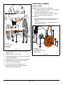
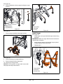
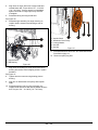
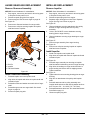
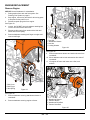
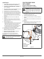
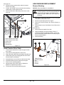
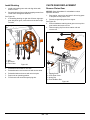
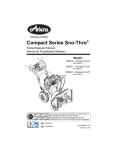
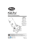
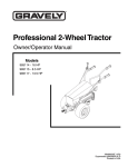
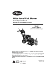
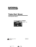
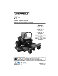
Service Guide
Model
920402 – Sno-Tek 24E
(SN 175000 +)
E10
ENGLISH
04854400 • 4/15
TABLE OF CONTENTS
SAFETY . . . . . . . . . . . . . . . . . . . . . . . . . . . . . 3
PRACTICES & LAWS . . . . . . . . . . . . . . . . . . 3
REQUIRED OPERATOR TRAINING . . . . . . . 3
SAFETY ALERT SYMBOL . . . . . . . . . . . . . . 3
SIGNAL WORDS . . . . . . . . . . . . . . . . . . . . . . 3
SAFETY DECALS . . . . . . . . . . . . . . . . . . . . . 4
SAFETY RULES . . . . . . . . . . . . . . . . . . . . . . 5
DRAINING FUEL SYSTEM . . . . . . . . . . . . . . 8
SERVICE POSITION . . . . . . . . . . . . . . . . . . . 8
BOTTOM COVER REMOVAL . . . . . . . . . . . . 9
SEPARATE AUGER HOUSING
FROM FRAME . . . . . . . . . . . . . . . . . . . . . . . 10
ATTACHMENT DRIVE BELT
REPLACEMENT . . . . . . . . . . . . . . . . . . . . . . 12
TRACTION DRIVE BELT
REPLACEMENT . . . . . . . . . . . . . . . . . . . . . . 13
ATTACHMENT BRAKE REPLACEMENT. . . 15
FRICTION DISC REPLACEMENT. . . . . . . . . 16
AUGER REPLACEMENT . . . . . . . . . . . . . . . 18
AUGER GEARCASE REPLACEMENT . . . . . 21
IMPELLER REPLACEMENT . . . . . . . . . . . . . 21
ENGINE REPLACEMENT . . . . . . . . . . . . . . . 22
TRACTION DRIVE CABLE
REPLACEMENT . . . . . . . . . . . . . . . . . . . . . . 23
AXLE BUSHING REPLACEMENT . . . . . . . . 24
CHUTE GEAR REPLACEMENT . . . . . . . . . . 25
SCRAPER BLADE REPLACEMENT . . . . . . 27
SERVICE PARTS. . . . . . . . . . . . . . . . . . . . . . 28
SERVICE RECORD . . . . . . . . . . . . . . . . . . . . 29
EN – 1
WELCOME
Before operating or servicing the unit, carefully and completely read the Operator’s Manual and
engine manual provided with the unit at time of purchase. They contain important safety instructions
and information about unit controls.
Have Questions or Need Assistance?
www.ariens.com
920-756-4688
To find your nearest authorized Ariens service dealer, visit
ariens.com and click “Where to Buy”.
A Parts Manual and an Operator’s Manual for your unit is
available for free download or purchase at www.ariens.com.
Ariens recommends using only genuine Ariens replacement parts on this unit. Using unauthorized
parts may adversely affect the performance, durability or safety of this unit and may void the warranty.
Installing unauthorized parts will not automatically void the warranty; however, the warranty will not
apply if the installation and use of unauthorized parts damages the unit. The Ariens warranty applies
solely to defects in Ariens materials and / or factory workmanship. Ariens disclaims liability for any
claims or damages – whether warranty, property damage, personal injury or death – arising from using
unauthorized replacement parts.
Be aware of your mechanical aptitude when applying information in this manual for service and / or
repairs. If you are not comfortable or capable of completing service and /or repairs to the machine,
take the machine to an authorized Ariens service dealer.
EN – 2
SIGNAL WORDS
SAFETY
Read these safety rules and follow them closely. Failure to
follow these rules could lead to loss of control of unit,
severe personal injury or death to you or bystanders, or
result in damage to property or the machine.
The safety alert symbol above and signal words below are
used on decals and in this manual. Read and understand
all safety messages.
1. Danger
DANGER: Indicates an IMMINENTLY
HAZARDOUS SITUATION! If not avoided, WILL
RESULT in death or serious injury.
PRACTICES & LAWS
Practice usual and customary safe working precautions.
Learn applicable rules and laws in your area. Always follow
the practices set forth in this manual.
2. Warning
WARNING: Indicates a POTENTIALLY
HAZARDOUS SITUATION! If not avoided,
COULD RESULT in death or serious injury.
REQUIRED OPERATOR TRAINING
The original purchaser of this unit was instructed by the
seller on safe and proper operation. If unit is to be used by
someone other than the original purchaser, loaned, rented,
or sold, ALWAYS provide this manual and any needed
safety training before operation.
WARNING: AVOID INJURY. This snow thrower
is capable of crushing or amputating body parts.
Failure to observe the safety instructions in the
manuals and on decals could result in serious
injury or death.
ALWAYS disengage auger, stop unit and engine,
remove key and allow moving parts to stop
before leaving operator’s position.
SAFETY ALERT SYMBOL
3. Caution
CAUTION: Indicates a POTENTIALLY
HAZARDOUS SITUATION! If not avoided, MAY
RESULT in minor or moderate injury. It may also
be used to alert against unsafe practices.
4. Notice
NOTICE: Indicates information or procedures that are
considered important but not hazard related. If not
followed, property damage could result.
5. Important
IMPORTANT: Indicates general reference information
worthy of special attention.
This is the safety alert symbol. It means:
• ATTENTION!
• YOUR SAFETY IS INVOLVED!
When you see this symbol:
• BECOME ALERT!
• OBEY THE MESSAGE!
EN – 3
SAFETY DECALS
Stop engine, remove key, and read manual
before making any repairs or adjustments.
The safety decals on your machine are visual reminders of
the important safety information in this manual. All
messages on your unit must be fully understood and
carefully followed. Safety decals on the machine are
explained below.
Read Operator’s Manual.
Always replace missing or damaged safety decals.
Replacement decal information is in the parts manual for
your machine. Decals can be ordered from your dealer.
See Figure 1 for safety decal locations.
Wear appropriate hearing protection.
Safety Decal Locations
1
2. DANGER!
Danger!
2
ROTATING PARTS! Only use clean-out tool
to clear blockages. NEVER use your hands.
3
High-speed auger/impeller rotates below
discharge opening. Wait for all moving parts
to stop before removing clogs or servicing.
Figure 1
Safety Decal Descriptions
3. DANGER!
1. CAUTION!
Danger!
Danger!
ROTATING PARTS! Keep clear of auger
while engine is running.
• Read Operator’s Manual.
Only use clean-out tool to clear blockages.
NEVER use your hands.
• Allow operation only by properly-trained
adult, never children.
NEVER direct discharge towards persons or
property that may be injured or damaged by
thrown objects.
Keep people away from unit while operating.
Keep children out of work area and under
watchful care of a responsible adult.
EN – 4
• Stop engine and remove ignition key prior
to leaving the operator’s position for any
reason.
• Keep all controls, guards and safety
devices properly serviced and functional.
• NEVER direct discharge towards persons
or property that may be injured or damaged
by thrown objects.
SAFETY RULES
Handle fuel with care; it is highly flammable.
The following safety instructions are based on the B71.3
specifications of the American National Standards Institute
in effect at the time of production.
• Use an approved fuel container.
Training
Read, understand and follow all instructions on the
machine and in the manual(s) before operating this unit.
Be thoroughly familiar with the controls and the proper use
of the equipment. Know how to stop the unit and
disengage the controls quickly.
Never allow children to operate or play on or near the
equipment. Never allow adults to operate the equipment
without proper instruction.
• Never fill containers inside a vehicle or on a truck or
trailer bed with a plastic liner. Always place containers
on the ground, away from your vehicle, before filling.
• When practical, remove gas-powered equipment from
the truck or trailer and refuel it on the ground. If this is
not possible, then refuel such equipment on a trailer
with a portable container, rather than from a gasoline
dispenser nozzle.
• Replace gasoline cap securely and wipe up spilled fuel.
Exercise caution to avoid slipping or falling, especially
when operating the snow thrower in reverse.
• If fuel is spilled on clothing, change clothing
immediately.
Always remove key and/or wire from spark plug before
assembly, maintenance or service. Unintentional engine
start up can cause death or serious injury.
Adjust the auger / impeller housing height to clear gravel
or crushed rock surface.
Complete a walk-around inspection of the unit to
understand the unit, your work area and all safety decals.
Understand how to operate all controls, the functions of all
controls and how to STOP in an emergency.
Preparation
Never attempt to make any adjustments while the engine
is running (except when specifically recommended by
manufacturer).
Always allow unit and engine to adjust to outdoor
temperature before clearing snow.
Operation
Always check overhead and side clearances carefully
before operation.
Disengage all controls before starting engine.
Always be aware of traffic when operating near streets or
along curbs.
Thoroughly inspect the area where the equipment is to be
used and remove all doormats, sleds, boards, toys, wires
and other foreign objects.
Use extension cords and receptacles as specified by the
manufacturer for all units with electric drive motors or
electric starting motors.
• Fill fuel tank outdoors with extreme care. Never fill fuel
tank indoors.
• Keep the nozzle in contact with the rim of the fuel tank
or container opening at all times, until refueling is
complete. Do not use a nozzle lock-open device.
Keep the area of operation clear of all persons,
particularly small children. Be alert and shut off unit if
children enter area.
Disengage all clutches and shift into neutral before
starting the engine.
• Never add fuel to a running engine or hot engine.
Never leave a running unit unattended. Always stop
engine and remove key before leaving unit to prevent
unauthorized use.
Do not put hands or feet near or under rotating parts.
Keep clear of the discharge opening at all times.
Moving and/or rotating parts can cut off body parts such
as fingers or a hand. NEVER place your hands, other
body part or clothing near any moving parts while unit is
running.
Always keep hands away from all pinch points.
Do not touch parts which might be hot from operation.
Allow parts to cool before attempting to maintain, adjust or
service.
Thrown objects can cause injury. Check for weak spots on
docks, ramps or floors. Avoid uneven work areas and
rough terrain and stay alert for hidden hazards.
Exercise extreme caution when operating on or crossing
gravel drives, walks or roads. Stay alert for hidden
hazards or traffic.
EN – 5
After striking a foreign object, stop the engine, remove the
wire from the spark plug, disconnect the cord on electric
motors, thoroughly inspect the snow thrower for any
damage, and repair the damage before restarting and
operating the snow thrower.
If the unit should start to vibrate abnormally, stop the
engine and check immediately for the cause. Vibration is
generally a warning of trouble.
Stop the engine whenever you leave the operating
position, before unclogging the auger / impeller housing or
discharge chute, and when making any repairs,
adjustments or inspections.
When cleaning, repairing or inspecting the snow thrower,
stop the engine and make certain the auger / impeller and
all moving parts have stopped. Disconnect the spark plug
wire and keep the wire away from the plug to prevent
someone from accidentally starting the engine.
Do not run the engine indoors, except when starting the
engine and for transporting the snow thrower in or out of
the building. Open the outside doors; exhaust fumes are
dangerous.
Never operate the snow thrower without good visibility or
light. Always be sure of your footing, and keep a firm hold
on the handles. Walk; never run.
Never operate unit after or during the use of medication,
drugs or alcohol. Safe operation requires complete and
unimpaired attention at all times.
Never allow anyone to operate this unit when their
alertness or coordination is impaired.
Never touch a hot engine or muffler.
Avoid contact with sharp edges; sharp edges can cut.
Do not throw snow higher than necessary.
Clearing a Clogged Discharge Chute
Hand contact with the rotating auger / impeller inside the
discharge chute is the most common cause of injury
associated with snow throwers. Never use your hand to
clean out the discharge chute.
To clear the chute:
Never operate the snow thrower without proper guards,
and other safety protective devices in place and working.
Always stand clear of the discharge area when operating
this unit.
Never direct the discharge toward people or areas where
injury or property damage can occur from thrown objects.
Keep children and others away.
Do not overload the machine capacity by attempting to
clear snow at too fast a rate.
Never operate the machine at high transport speeds on
slippery surfaces. Look behind and use care when
operating in reverse.
Do not operate in reverse unless absolutely necessary.
Always back up slowly and look down and behind before
and while backing.
Do not carry passengers.
Disengage attachment when not in use and when
traveling from one work area to another.
1.
SHUT THE ENGINE OFF!
2.
Wait 10 seconds to be sure the auger / impeller
blades have stopped rotating.
3.
Always use a clean-out tool, not your hands.
Maintenance and Storage
Secure unit so it will not tip over during maintenance.
Before cleaning, removing clogs or making any
inspections, repairs, etc., disengage clutch(es), stop
engine, remove key, allow moving parts to stop and hot
parts to cool.
Check shear bolts and other bolts at frequent intervals for
proper tightness to be sure the equipment is in safe
working condition.
Check clutch and brake operation frequently.
Do not change engine governor settings and do not overspeed engine.
Adjust and service as required. Motion of drive wheels
and auger / impeller must stop quickly when clutch levers
are released.
Disengage power to the auger / impeller when snow
thrower is transported or not in use.
Use only attachments and accessories approved by the
manufacturer of the snow thrower (such as wheel weights,
counterweights or cabs).
This product is equipped with an internal combustion
engine. Do not use unit on or near any unimproved,
forest-covered or brush-covered land unless exhaust
system is equipped with a spark arrester meeting
applicable local, state or federal laws. A spark arrester, if
used, must be maintained in effective working order by
operator.
Always maintain unit in safe operating condition.
Damaged or worn out muffler can cause fire or explosion.
Keep unit free of ice or other debris. Clean up oil or fuel
spills.
Always keep protective structures, guards, and panels in
good repair and secured in place. Never modify or remove
safety devices.
Never store the machine with fuel in the fuel tank inside a
building where ignition sources are present such as hot
water heaters, space heaters or clothes dryers. Close fuel
valve and allow the engine to cool completely before
storing in any enclosure or covering the unit.
EN – 6
Always refer to operator's manual for important details if
the snow thrower is to be stored for an extended period.
Never fill fuel containers inside a vehicle or on a truck or
trailer bed with a plastic liner. Always place containers on
the ground away from your vehicle before filling.
Maintain or replace safety and instruction labels as
necessary.
When practical, remove gas-powered equipment from the
truck or trailer and refuel it on the ground. If this is not
possible, then refuel on a trailer with a portable container,
rather than from a gasoline dispenser nozzle.
Run the machine a few minutes after throwing snow to
prevent freeze-up of the auger / impeller.
Keep the nozzle in contact with the rim of the fuel tank or
container opening at all times until fueling is complete. Do
not use a nozzle lock-open device.
Personal Protection
Do not operate the equipment without wearing adequate
winter garments. Avoid loose fitting clothing that can get
caught in moving parts. Wear footwear that will improve
footing on slippery surfaces.
If fuel is spilled on clothing, change clothing immediately.
Wear adequate safety gear, including safety glasses with
side shields and protective gloves.
Do not wear loose clothing or jewelry, and tie back hair
that may get caught in rotating parts.
Properly remove fuel before tipping unit up onto housing
to avoid spills.
Towing/Transporting
Always stop engine, remove key and close fuel valve or
drain fuel when transporting unit on a truck or trailer.
NEVER attempt to unclog or clean unit while engine is
running. Rotating auger / impeller can cause serious
injury.
Use extra care when loading or unloading unit onto trailer
or truck. Secure unit chassis to transport vehicle. Never
secure from rods or linkages that could be damaged. Do
not transport machine while engine is running.
Protect eyes, face and head from objects that may be
thrown from unit. Wear appropriate hearing protection.
Always wear safety glasses or eye shields during
operation or while performing an adjustment or repair to
protect eyes from foreign objects that may be thrown from
the machine.
Slope Operation
Accessories
Use only Ariens Company-recommended attachments or
accessories that are designed for your unit and that are
appropriate to your use and can be used safely in your
application.
Exercise extreme caution when operating on slopes. DO
NOT operate on steep slopes. DO NOT clear snow across
the face of slopes; go up and down. Keep all movement
on slopes slow and gradual.
Use a slow speed to avoid stops or shifts on slopes. Avoid
starting or stopping on a slope. Do not park unit on a slope
unless absolutely necessary. When parking on a slope
always block the wheels.
Do not operate near drop-offs, ditches, or embankments.
Unit can suddenly turn over if a wheel is over the edge of
a cliff or ditch, or if an edge caves in.
Fuel
DO NOT run engine in an enclosed area. Always provide
good ventilation. Fumes from engine exhaust can cause
injury or death.
Fuel is highly flammable and its vapors are explosive.
Handle with care. Use only an approved gasoline
container with an appropriately-sized dispensing spout.
No smoking, no sparks, no flames. Always allow engine to
cool before servicing.
Never fill fuel tank when engine is running or hot from
operation.
Never fill or drain fuel tank indoors.
Replace fuel cap securely and clean up spilled fuel.
EN – 7
DRAINING FUEL SYSTEM
1.
Move unit to an open, well-ventilated area with no
flames or sparks.
2.
Remove cap from fuel tank and siphon fuel into a
clean gasoline container.
SERVICE POSITION
WARNING: AVOID INJURY. Before placing unit
in service position, close fuel valve and drain fuel
from tank and fuel system. See Draining Fuel
System on page 8. Make sure unit is secure and
will not tip.
3.
Reinstall cap onto fuel tank and tighten.
4.
Start engine to burn remaining fuel in fuel system and
leave engine running until it “runs dry” and stops.
Refer to Operator’s Manual for engine start procedure.
5.
See Figure 2.
IMPORTANT: NEVER store unit in service position.
Stop engine, remove key and close fuel valve.
Figure 2
EN – 8
BOTTOM COVER REMOVAL
See Figure 4.
5.
NOTICE: Save all hardware for reinstallation.
WARNING: AVOID INJURY. Before placing unit
in service position, close fuel valve and drain fuel
from tank and fuel system. See Draining Fuel
System on page 8. Make sure unit is secure and
will not tip.
1.
Stop engine, remove key and wait for all moving parts
to stop and for hot parts to cool.
2.
Disconnect spark plug wire from engine.
3.
Place unit in service position. See Service Position on
page 8.
Remove hardware retaining bottom cover to frame
and remove cover.
2
See Figure 3.
4.
Remove lock pins from axle ends and remove wheels.
NOTICE: Grease axle before reinstalling wheels.
1
1. Bottom Cover
2. Hex Bolt
1
Figure 4
1. Axle Lock Pin
2. Wheel
2
Figure 3
EN – 9
SEPARATE AUGER HOUSING FROM
FRAME
NOTICE: Save all hardware for reinstallation.
1.
Stop engine, remove key and wait for all moving parts
to stop and for hot parts to cool.
2.
Disconnect spark plug wire from engine.
4
See Figure 5.
3.
Remove spring clip from chute rotation rod and
remove rod.
1
1
3
5
2
1.
2.
3.
4.
5.
2
Sleeve Bushing
Hairpin
Cable Snap
Deflector Arm
Deflector Anchor
Figure 6
See Figure 7.
6.
Loosen, but DO NOT remove hardware securing belt
cover to unit and remove belt cover.
1. Spring Clip
2. Chute Rotation Rod
Figure 5
See Figure 6.
4.
Remove hairpin and sleeve bushing securing chute
deflector cable to deflector arm under control panel.
5.
Remove cable from deflector arm and remove cable
snap from deflector anchor.
1
2
1. Belt Cover
2. Tapping Screw
Figure 7
EN – 10
See Figure 8.
See Figure 9.
7.
Remove hardware securing belt finger to engine and
remove belt finger.
9.
8.
Remove attachment drive belt from attachment
sheave.
Position support, such as a trash can, under
handlebars so tractor / frame remains upright when
separated from auger housing.
5
4
6
3
2
Figure 9
1
See Figure 10.
10. Remove hardware securing auger housing to frame.
11. Tip auger housing apart from frame on mount rod and
separate housing from unit.
1.
2.
3.
4.
5.
6.
Attachment Drive Belt
Belt Finger
Attachment Sheave
Flat Steel Washer
Locking Washer
Hex Bolt
Figure 8
1
2
1. Tapping Screw
2. Mount Rod
Figure 10
EN – 11
ATTACHMENT DRIVE BELT
REPLACEMENT
Remove Attachment Drive Belt
NOTICE: Save all hardware for reinstallation.
1.
Stop engine, remove key and wait for all moving parts
to stop and for hot parts to cool.
2.
Disconnect spark plug wire from engine.
3.
Separate auger housing from frame. See Separate
Auger Housing from Frame on page 10.
1
See Figure 11.
4.
Remove attachment drive belt from attachment drive
pulley.
3
2
1. Attachment Brake
2. Mount Rod
3. Mount Bracket
Figure 12
1
2
1. Attachment Drive Belt
2. Attachment Drive Pulley
Release attachment clutch lever.
5.
Align top holes in housing mount brackets with holes
in frame and reinstall, but DO NOT tighten four
tapping screws.
6.
Check tire pressure and adjust if necessary. Refer to
Operator’s Manual for specification.
7.
Place unit on a flat, level surface.
8.
Loosen hardware securing skid shoes to auger
housing.
9.
Torque tapping screws installed in step 5 to
16.8 – 25.2 lbf-ft (22.8 – 34.1 N•m).
See Figure 13.
Figure 11
10. Install belt onto attachment sheave.
Install Attachment Drive Belt
1.
4.
11. Reinstall belt finger and secure with two flat steel
washers, two locking washers and two hex bolts.
Tighten hardware.
Install belt onto attachment drive pulley.
See Figure 12.
2.
Engage attachment clutch lever so attachment brake
will not obstruct attachment drive pulley in step 3.
3.
Tilt auger housing rear up and lower into frame so
housing mount brackets sit on mount rod.
12. Check belt finger clearance:
• Engage attachment clutch lever and make sure belt
finger located opposite belt idler is less than 1/8"
(3.2 mm) from belt, but not touching the belt.
• If needed, adjust clearance by loosening hex bolts,
repositioning belt finger, and tightening bolts.
EN – 12
TRACTION DRIVE BELT
REPLACEMENT
Remove Traction Drive Belt
NOTICE: Save all hardware for reinstallation.
4
1.
Stop engine, remove key and wait for all moving parts
to stop and for hot parts to cool.
2.
Disconnect spark plug wire from engine.
3.
Separate auger housing from frame. See Separate
Auger Housing from Frame on page 10.
5
See Figure 14.
6
4.
Disconnect idler spring from traction drive idler.
5.
Disconnect swing gate return spring from frame.
6.
Remove hardware securing swing gate spacer to
frame and remove swing gate spacer.
7.
Slide swing gate left so swing gate tab is out of stop
hole in frame.
8.
Move swing gate forward to access traction drive belt
and remove belt.
2
1
NOTICE: It may be necessary to slowly pull recoil starter
handle to turn traction sheave to remove belt.
3
2
1.
2.
3.
4.
5.
6.
6
7
Attachment Sheave
Belt Finger
Attachment Drive Belt
Hex Bolt
Locking Washer
Flat Steel Washer
Figure 13
8
13. Reinstall belt cover and tighten hardware.
14. Reinstall chute rotation rod into chute rotation gear
and secure with spring clip.
15. Reinstall chute deflector cable snap into deflector
anchor and deflector cable eyelet onto deflector arm.
Secure with sleeve bushing and hairpin. See Figure 6.
16. Adjust skid shoes. Refer to Operator’s Manual for
adjustment procedure.
17. Adjust attachment clutch / brake. Refer to Operator’s
Manual for adjustment procedure.
1
18. Reconnect spark plug wire.
IMPORTANT: Check all adjustments after first use.
WARNING: AVOID INJURY. Auger / impeller
must stop within 5 seconds when attachment
clutch lever is released.
1.
2.
3.
4.
5.
6.
7.
8.
EN – 13
Tapping Screw
Swing Gate Spacer
Swing Gate Return Spring
Swing Gate
Swing Gate Tab & Stop Hole
Traction Drive Idler
Traction Sheave
Idler Spring
Figure 14
4
3
5
Install Traction Drive Belt
9.
See Figure 15.
10. Adjust traction drive clutch. Refer to Operator’s
Manual for adjustment procedure.
1.
Install belt onto traction drive pulley.
2.
Install belt onto traction sheave.
3.
Move swing gate so swing gate tab aligns with stop
hole in frame.
11. Reconnect spark plug wire.
IMPORTANT: Check all adjustments after first use.
IMPORTANT: Make sure support bushing is correctly
seated in frame and is flush with frame.
4.
Slide swing gate right so top of swing gate inserts
through support bushing and swing gate tab inserts
through stop hole.
IMPORTANT: Make sure pivot bushing is correctly seated
in frame and is flush with frame.
5.
Reinstall swing gate spacer.
6.
Align pivot bushing holes with holes in frame and
swing gate spacer. Secure with two tapping screws.
7.
Reconnect idler spring to traction drive idler.
8.
Reconnect swing gate return spring to frame.
3
8
7
2
4
5
1
6
1.
2.
3.
4.
5.
6.
7.
8.
Reinstall attachment drive belt. See Install Attachment
Drive Belt on page 12.
Traction Drive Pulley
Traction Drive Belt
Traction Sheave
Support Bushing
Swing Gate Tab & Stop Hole
Pivot Bushing
Idler Spring
Traction Drive Idler
Figure 15
EN – 14
ATTACHMENT BRAKE REPLACEMENT
See Figures 17 and 18.
Remove Attachment Brake
5.
NOTICE: Save all hardware for reinstallation.
1.
Stop engine, remove key and wait for all moving parts
to stop and for hot parts to cool.
2.
Disconnect spark plug wire from engine.
3.
Separate auger housing from frame. See Separate
Auger Housing from Frame on page 10.
Engage and disengage attachment clutch to verify
brake roller on attachment idler does not interfere with
brake pad.
IMPORTANT: Make sure rolling action of brake roller does
not seize.
Attachment Clutch Disengaged / Brake Engaged
See Figure 16.
4.
Remove hardware securing attachment brake arm to
brake mount bracket.
5.
Disconnect extension spring from attachment brake
arm and remove attachment brake arm.
2
1. Brake Pad
2. Brake Roller
1
Figure 17
6
5
1.
2.
3.
4.
5.
6.
4
3
Hex Nut
Sleeve Bushing
Hex Bolt
Attachment Brake Arm
Tension Spring
Brake Mount Bracket
1
Attachment Clutch Engaged / Brake Disengaged
2
2
Figure 16
1
1. Brake Pad
2. Brake Roller
Install Attachment Brake
1.
Align pivoting end of new attachment brake arm with
hole in brake mount bracket.
2.
Reinstall sleeve bushing into attachment brake arm.
3.
Secure attachment brake arm to brake mount bracket
with hex bolt and hex nut, but DO NOT overtighten.
4.
Reconnect tension spring to attachment brake arm.
Figure 18
6.
Reinstall attachment drive belt. See Install Attachment
Drive Belt on page 12.
WARNING: AVOID INJURY. Before placing unit
in service position, close fuel valve and drain fuel
from tank and fuel system. See Draining Fuel
System on page 8. Make sure unit is secure and
will not tip.
7.
EN – 15
Place unit in service position. See Service Position on
page 8.
8.
Remove bottom cover. See Bottom Cover Removal on
page 9.
See Figure 19.
9.
FRICTION DISC REPLACEMENT
Remove Friction Disc
NOTICE: Save all hardware for reinstallation.
Check attachment brake:
• Brake must contact attachment belt when
attachment clutch is disengaged.
WARNING: AVOID INJURY. Before placing unit
in service position, close fuel valve and drain fuel
from tank and fuel system. See Draining Fuel
System on page 8. Make sure unit is secure and
will not tip.
• Brake must be more than 1.6 mm away from
attachment belt when attachment clutch is engaged.
1
2
1.
Stop engine, remove key and wait for all moving parts
to stop and for hot parts to cool.
2.
Disconnect spark plug wire from engine.
3.
Place unit in service position. See Service Position on
page 8.
4.
Remove bottom cover. See Bottom Cover Removal on
page 9.
See Figure 20.
5.
Remove hairpin securing adjustment pivot pin to
speed selector arm and remove adjustment pivot pin
from speed selector arm.
2
3
1. Attachment Drive Belt
2. Brake Pad
Figure 19
10. Reinstall bottom cover and secure with six hex bolts.
11. Reinstall wheels and secure with axle lock pins.
1
12. Return unit to operating position and fill fuel tank.
13. Adjust attachment clutch / brake. Refer to Operator’s
Manual for adjustment procedure.
14. Reconnect spark plug wire.
WARNING: AVOID INJURY. Auger / impeller
must stop within 5 seconds when attachment
clutch lever is released.
1. Speed Selector Arm
2. Hairpin
3. Adjustment Pivot Pin
Figure 20
EN – 16
See Figure 21.
See Figure 23.
6.
Remove spring clip from right side of hex shaft.
7.
Remove hardware securing left flange bearing to
frame and remove flange bearing.
10. Remove hardware securing friction disc to drive
carrier and remove friction disc.
2
2
3
1
3
4
1.
2.
3.
4.
1. Friction Disc
2. Drive Carrier
3. Tapping Screw
1
Flange Bearing
Hex Shaft
Spring Clip
Tapping Screw
Figure 23
Install Friction Disc
Figure 21
1.
Install new friction disc to drive carrier with cup side
positioned toward drive carrier.
2.
Secure friction disc to drive carrier with three tapping
screws. Torque to 5 – 6 lbf-ft (7 – 8 N•m).
See Figure 22.
See Figure 24.
8.
Slide hex shaft left and remove pinion gear and flat
steel washer from hex shaft.
3.
9.
Continue sliding hex shaft left and remove friction disc
assembly from unit.
Reinstall friction disc assembly into shift fork. Make
sure washers on assembly are positioned against shift
fork as shown.
4.
Reinstall hex shaft through frame and friction disc
assembly.
5.
Reinstall pinion gear and flat steel washer onto hex
shaft.
6.
Align pinion gear with spur gear and insert hex shaft
into frame and flange bearing.
2
1.
2.
3.
4.
1
Friction Disc Assembly
Hex Shaft
Pinion Gear
Flat Steel Washer
Figure 22
3
4
EN – 17
AUGER REPLACEMENT
Remove Auger
NOTICE: Save all hardware for reinstallation.
2
1.
Stop engine, remove key and wait for all moving parts
to stop and for hot parts to cool.
2.
Disconnect spark plug wire from engine.
3.
Separate auger housing from frame. See Separate
Auger Housing from Frame on page 10.
See Figure 25.
4.
Remove hardware securing attachment drive pulley
assembly to auger housing and remove pulley
assembly.
5.
Loosen, but DO NOT remove hardware securing
bearing plate to housing.
3
2
2
1.
2.
3.
4.
1
3
1
4
Shift Fork
Flat Steel Washer
Pinion Gear
Spur Gear
4
1.
2.
3.
4.
Figure 24
7.
Reinstall left flange bearing and secure with three
tapping screws.
8.
Reinstall spring clip into hex shaft.
9.
Reinstall adjustment pivot pin into speed selector arm
and secure with hairpin.
Hex Bolt
Locking Washer
Attachment Drive Pulley
Bearing Plate
Figure 25
10. Reinstall bottom cover and secure with six hex bolts.
11. Reinstall wheels and secure with axle lock pins.
12. Return unit to operating position.
13. Fill fuel tank and reconnect spark plug wire.
14. Adjust speed selector lever. Refer to Operator’s
Manual for adjustment procedure.
EN – 18
See Figure 26.
6.
3
Remove hardware securing auger bushings to auger
housing.
2
1
1
2
1. Tapping Screw
2. Auger Bushing
Figure 26
1. Shear Bolt
2. Bushing
3. Auger
Figure 28
See Figure 27.
7.
Remove auger assembly from auger housing.
Install Auger
See Figure 29.
1.
Install auger onto auger shaft with auger kickers facing
gearcase.
IMPORTANT: Make sure auger helix direction matches the
original auger orientation.
2.
Apply grease to grease zerk and spin auger by hand
to spread grease along auger shaft.
3.
Repeat step 2.
Figure 27
See Figure 28.
8.
Remove bushing from auger shaft end.
9.
Remove shear bolt from auger shaft.
10. Slide auger off auger shaft.
2
NOTICE: If rust is present on auger shaft, remove with
sand paper and wipe clean with oil.
1
3
1. Auger Kicker
2. Gearcase
3. Grease Zerk
Figure 29
EN – 19
4.
5.
Align holes in auger with holes in auger shaft and
reinstall shear bolt. Torque bolt to 5.8 – 12.2 lbf-ft
(7.9 – 16.5 N•m). If torque wrench is unavailable,
tighten until bolts no longer spin freely. DO NOT
overtighten.
5
Reinstall bushing onto auger shaft end.
See Figure 30.
6.
Reinstall auger assembly into auger housing so
impeller shaft is seated in ball bearing at rear of
housing.
3
1
2
1.
2.
3.
4.
5.
1
Impeller Shaft
Attachment Drive Pulley
Locking Washer
Hex Bolt
Hex Nut
Figure 31
4
2
11. Reinstall attachment drive belt. See Install Attachment
Drive Belt on page 12.
12. Reconnect spark plug wire.
1. Impeller Shaft
2. Ball Bearing
7.
Figure 30
Align holes in bushings on auger ends with holes in
housing and secure with six tapping screws. Tighten
hardware.
See Figure 31.
8.
Tighten three hex nuts securing bearing plate to
housing.
9.
Align hub on attachment drive pulley with impeller
shaft.
10. Reinstall attachment drive pulley assembly onto
impeller shaft and secure with locking washer and hex
bolt. Torque to 5.8 – 12.2 lbf-ft (7.9 – 16.5 N•m).
EN – 20
AUGER GEARCASE REPLACEMENT
IMPELLER REPLACEMENT
Remove Gearcase Assembly
Remove Impeller
NOTICE: Save all hardware for reinstallation.
NOTICE: Save all hardware for reinstallation.
1.
Stop engine, remove key and wait for all moving parts
to stop and for hot parts to cool.
1.
Stop engine, remove key and wait for all moving parts
to stop and for hot parts to cool.
2.
Disconnect spark plug wire from engine.
2.
Disconnect spark plug wire from engine.
3.
Remove augers. See Remove Auger on page 18.
3.
Separate auger housing from frame. See Separate
Auger Housing from Frame on page 10.
See Figure 32.
4.
Remove two flat steel washers from auger shaft.
See Figure 25.
5.
Remove two roll pins securing impeller to impeller
shaft and remove impeller.
4.
Remove hardware securing attachment drive pulley
and hub to auger housing and remove pulley
assembly.
5.
Loosen, but DO NOT remove hardware securing
bearing plate to auger housing.
6.
Remove hardware securing auger bushings to auger
housing.
See Figure 27.
2
7.
Remove auger assembly from auger housing.
See Figure 32.
8.
Remove two roll pins securing impeller to impeller
shaft and remove impeller.
Install Impeller
3
1.
Install new impeller onto impeller shaft.
2.
Align holes in impeller with holes in impeller shaft and
reinstall roll pins.
1
See Figure 30.
1. Roll Pin
2. Impeller
3. Flat Steel Washer
Figure 32
3.
Reinstall auger assembly into housing so impeller
shaft is seated in ball bearing at rear of auger housing.
4.
Align holes in bushings on auger ends with holes in
auger housing and secure with six tapping screws.
Tighten hardware.
See Figure 31.
Install Gearcase Assembly
5.
Tighten three hex nuts securing bearing plate to auger
housing.
1.
Reinstall impeller onto new impeller shaft.
2.
Align holes in impeller with holes in impeller shaft and
reinstall roll pins.
6.
Align hub on attachment drive pulley with impeller
shaft.
3.
Reinstall one flat steel washer onto each side of auger
shaft.
7.
4.
Reinstall augers onto new auger shaft. See Install
Auger on page 19.
Reinstall attachment drive pulley assembly onto
impeller shaft and secure with locking washer and hex
bolt. Torque to 5.8 – 12.2 lbf-ft (7.9 – 16.5 N•m).
8.
5.
Reconnect spark plug wire.
Reinstall attachment drive belt. See Install Attachment
Drive Belt on page 12.
9.
Reconnect spark plug wire.
EN – 21
ENGINE REPLACEMENT
Remove Engine
NOTICE: Save all hardware for reinstallation.
1.
Drain gasoline from tank and fuel system. See
Draining Fuel System on page 8.
2.
Stop engine, remove key and wait for all moving parts
to stop and for hot parts to cool.
3.
Disconnect spark plug wire from engine.
2
3
4
See Figure 33.
4.
Loosen, but DO NOT remove hardware retaining belt
cover to unit and remove belt cover.
5.
Disconnect idler spring from traction drive idler and
frame and remove spring.
6.
Remove hardware retaining belt finger to engine and
remove belt finger.
1
4
1.
2.
3.
4.
Hex Bolt
Attachment Sheave
Hex Nut
Locking Washer
Figure 34
See Figure 35.
9.
1
Remove attachment sheave and traction sheave from
crankshaft.
10. Move attachment drive belt and traction drive belt off
crankshaft.
11. Lift engine off frame and lower onto a flat, level
surface.
2
4
1. Belt Cover
2. Belt Finger
3. Idler Spring
2
3
3
Figure 33
See Figure 34.
7.
Remove hardware securing attachment sheave to
crankshaft.
8.
Remove hardware securing engine to frame.
1
1.
2.
3.
4.
Attachment Sheave
Traction Sheave
Attachment Drive Belt
Traction Drive Belt
Figure 35
EN – 22
TRACTION DRIVE CABLE
REPLACEMENT
Install Engine
1.
Lower engine onto frame so weld screws in frame
insert through mounting holes in engine base.
2.
Reinstall four locking washers over weld screws and
secure with hex nuts. Torque to 8.8 – 13.2 lbf-ft
(11.9 – 17.9 N•m).
3.
Align traction sheave key with crankshaft keyway and
reinstall traction sheave onto crankshaft.
4.
Reinstall traction drive belt onto traction sheave.
5.
Reinstall idler spring to traction drive idler and frame.
6.
Align attachment sheave key with crankshaft keyway
and reinstall attachment sheave onto crankshaft.
Secure with locking washer and hex bolt and tighten
hardware.
Remove Traction Drive Cable
NOTICE: Save all hardware for reinstallation.
WARNING: AVOID INJURY. Before placing unit
in service position, close fuel valve and drain fuel
from tank and fuel system. See Draining Fuel
System on page 8. Make sure unit is secure and
will not tip.
1.
Stop engine, remove key and wait for all moving parts
to stop and for hot parts to cool.
2.
Disconnect spark plug wire from engine.
Place unit in service position. See Service Position on
page 8.
Remove bottom cover. See Bottom Cover Removal on
page 9.
7.
Reinstall attachment drive belt onto attachment
sheave.
3.
8.
Reinstall belt finger and secure with two flat steel
washers, two locking washers and two hex bolts as
shown in Figure 13.
4.
9.
Check belt finger clearance:
5.
See Figure 36.
Remove hairpin and flat steel washer securing cable
eyelet to swing gate and remove cable.
• Engage attachment clutch lever and make sure belt
finger located opposite belt idler is less than 1/8"
(3.2 mm) from belt, but not touching the belt.
• If needed, adjust clearance by loosening hex bolts,
repositioning belt finger, and tightening bolts.
10. Reinstall belt cover and tighten hardware.
11. Adjust attachment clutch / brake. Refer to Operator’s
Manual for adjustment procedure.
12. Adjust traction drive clutch. Refer to Operator’s
Manual for adjustment procedure.
1
13. Fill fuel tank and reconnect spark plug wire.
IMPORTANT: Check all adjustments after first use.
WARNING: AVOID INJURY. Auger / impeller
must stop within 5 seconds when attachment
clutch lever is released.
2
4
1.
2.
3.
4.
EN – 23
Hairpin
Flat Steel Washer
Cable Eyelet
Swing Gate
3
Figure 36
See Figure 37.
AXLE BUSHING REPLACEMENT
6.
Disconnect lower traction drive cable from upper
traction drive cable.
Remove Bushing
7.
Loosen, but DO NOT remove shoulder bolt retaining
cable pulley to cable pulley bracket.
8.
Remove cable from cable pulley and remove cable
from unit.
5
NOTICE: Save all hardware for reinstallation.
WARNING: AVOID INJURY. Before placing unit
in service position, close fuel valve and drain fuel
from tank and fuel system. See Draining Fuel
System on page 8. Make sure unit is secure and
will not tip.
1.
Stop engine, remove key and wait for all moving parts
to stop and for hot parts to cool.
2.
Disconnect spark plug wire from engine.
3.
Place unit in service position. See Service Position on
page 8.
4.
Remove bottom cover. See Bottom Cover Removal on
page 9.
See Figure 38.
1
1.
2.
3.
4.
5.
2
3
4
5.
Remove flat steel washer from axle.
6.
Remove hardware securing bushing to frame. If
replacing bushing on right side of frame, remove roll
pin from left side of axle and slide axle and spur gear
left to access hardware.
7.
Remove bushing.
Upper Traction Drive Cable
Lower Traction Drive Cable
Cable Pulley
Back Cover
Shoulder Bolt
Figure 37
2
5
3
Install Traction Drive Cable
1.
Connect lower traction drive cable to upper traction
drive cable.
2.
Feed cable end through hole in back cover.
3.
Align cable with cable pulley and tighten shoulder bolt.
4.
Install cable eyelet onto swing gate and secure with
flat steel washer and hairpin.
5.
Reinstall bottom cover and secure with six hex bolts.
6.
Reinstall wheels and secure with axle lock pins.
7.
Return unit to operating position.
8.
Adjust traction drive clutch. Refer to Operator’s
Manual for adjustment procedure.
9.
Fill fuel tank and reconnect spark plug wire.
4
1.
2.
3.
4.
5.
Tapping Screw
Flat Steel Washer
Axle
Roll Pin
Bushing
1
Figure 38
EN – 24
Install Bushing
CHUTE GEAR REPLACEMENT
1.
Install new bushing onto axle and align holes with
holes in frame.
Remove Pinion Gear
2.
Secure bushing to frame with two tapping screws from
inside frame and tighten hardware.
See Figure 39.
3.
If reinstalling bushing on right side of frame, align spur
gear with pinion gear, center axle and reinstall roll pin
into axle.
NOTICE: Save all hardware for reinstallation unless
specified otherwise.
1.
Stop engine, remove key and wait for all moving parts
to stop and for hot parts to cool.
2.
Disconnect spark plug wire from engine.
See Figure 40.
3.
Remove hardware retaining chute gear cover to pinion
gear bracket and remove cover.
4.
Remove spring clip from chute rotation rod and
remove rod.
1
2
4
1
1. Axle
2. Spur Gear
3. Pinion Gear
3
2
3
Figure 39
4.
Reinstall flat steel washer onto axle.
5.
Reinstall bottom cover and secure with six hex bolts.
6.
Reinstall wheels and secure with axle lock pins.
7.
Return unit to operating position.
8.
Fill fuel tank and reconnect spark plug wire.
1.
2.
3.
4.
Tapping Screw
Chute Gear Cover
Spring Clip
Chute Rotation Rod
Figure 40
EN – 25
See Figure 41.
See Figure 42.
5.
Remove push nut from pinion gear and discard.
5.
6.
Remove pinion gear and flat steel washer from pinion
gear bracket.
Remove hex nut from round head square neck bolt.
Catch compression spring, friction plate, and friction
washer as they fall off bolt.
6.
Remove round head square neck bolt from pedestal
plate and remove chute rotation gear.
2
1
4
3
5
6
4
3
7
1.
2.
3.
4.
Push Nut
Pinion Gear Bracket
Pinion Gear
Flat Steel Washer
2
1
Figure 41
Install Pinion Gear
1.
Install flat steel washer onto new pinion gear.
2.
Align pinion gear with chute rotation gear and insert
through pinion gear bracket. Secure with new push
nut.
3.
Reinstall chute rotation rod and secure with spring
clip.
4.
Reinstall chute gear cover and secure with two
tapping screws.
5.
Reconnect spark plug wire.
1.
2.
3.
4.
5.
6.
7.
Remove Chute Rotation Gear
NOTICE: Save all hardware for reinstallation.
1.
Stop engine, remove key and wait for all moving parts
to stop and for hot parts to cool.
2.
Disconnect spark plug wire from engine.
3.
Support discharge chute so it remains upright.
4.
Remove hardware retaining chute gear cover to pinion
gear bracket and remove cover.
EN – 26
Hex Nut
Compression Spring
Friction Plate
Friction Washer
Round Head Square Neck Bolt
Chute Rotation Gear
Pedestal Plate
Figure 42
Install Chute Rotation Gear
SCRAPER BLADE REPLACEMENT
1.
Remove Scraper Blade
Position discharge chute facing forward.
See Figure 43.
2.
Position chute rotation gear on chute mount so gear
teeth at halfway point align with pinion gear.
3.
NOTICE: Save all hardware for reinstallation.
WARNING: AVOID INJURY. Before placing unit
in service position, close fuel valve and drain fuel
from tank and fuel system. See Draining Fuel
System on page 8. Make sure unit is secure and
will not tip.
Align hole in chute gear with holes in chute mount, flat
steel washer, friction washer, and pedestal plate.
NOTICE: A flat steel washer and friction washer are
positioned between chute mount and pedestal plate and
are not to be removed.
4.
Insert round head square neck bolt through hole in
chute gear.
4
1.
Stop engine, remove key and wait for all moving parts
to stop and for hot parts to cool.
2.
Disconnect spark plug wire from engine.
3.
Place unit in service position. See Service Position on
page 8.
See Figure 44.
4.
2
Remove hardware securing scraper blade to auger
housing and remove scraper blade.
1
1
3
1.
2.
3.
4.
3
Chute Mount
Pedestal Plate
Chute Rotation Gear
Pinion Gear
1. Hex Nut
2. Scraper Blade
3. Flat Head Square Neck Bolt
Figure 44
Figure 43
5.
2
Install Scraper Blade
Reinstall friction washer, friction plate, compression
spring, and hex nut onto bolt. Tighten hex nut.
IMPORTANT: Make sure notch in friction plate fits around
tab in chute mount.
1.
Position new scraper blade inside auger housing and
align holes with holes in housing.
2.
Insert five flat head square neck bolts through holes
from inside auger housing and secure with hex nuts.
6.
Reinstall gear cover and secure with two tapping
screws.
3.
Return unit to operating position.
7.
Adjust discharge chute rotation. Refer to Operator’s
Manual for adjustment procedure.
4.
Adjust scraper blade and skid shoes. Refer to
Operator’s Manual for adjustment procedures.
8.
Reconnect spark plug wire.
5.
Fill fuel tank and reconnect spark plug wire.
EN – 27
SERVICE PARTS
Description
Part No.
Spark Plug
21547400
Attachment Drive Belt
07200513
Traction Drive Belt
07200603
Friction Disc
00170800
EN – 28
SERVICE RECORD
DATE
SERVICE PERFORMED
EN – 29
NOTES
655 West Ryan Street
Brillion, WI 54110
920-756-4688
Fax 920-756-2407
www.ariens.com
www.ariens.com.au