1
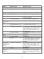
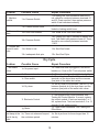
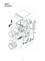
EQUATOR
SERVICE MANUAL
AND
SPARE PARTS CATALOG
First Edition - October 2003
COMBINATION WASHER-DRYER
MODELS: EZ 1500
EZ 2500 C
EZ 3600 C/CEE
www.WasherDryer.com
Advanced Appliances
Table Of Contents
WARRANTY INFORAMTION
TROUBLESHOOTING
1
2-6
INSTALLATION
WASH CYCLE
DRY CYCLE
2
2-5
5-6
SPARE PARTS CATALOG
7-18
CABINET
OSCILLATING GROUP
CONTROLS
WATER INLET
VENTILATION
7-9
10-12
13-14
15-16
17-18
TESTING THE ELECTRONIC CONTROL MODULE
19
TESTING THE DRIVE MOTOR
20
CIRCUIT DIAGRAM
21
TIMER CHART
22
WARRANTY INFORMATION
Your Equator appliance is protected by this warranty under normal,
personal, family or household use (1 Year), and limited commercial use
(90 days) in the USA and Canada.
WARRANTY SERVICE
WARRANTY
Equator Corporation undertakes to the consumer-owner This warranty is given by:
Equator Corporation,
to repair or, at Equator Corporation’s option, to replace
Equator Plaza,
any part of this product which proves to be defective in
2801 W. Sam Houston Pkwy. N.,
workmanship or material under normal personal, family
Houston, TX 77043-1611.
or household use, in the USA and Canada, for a period of
one year from the date of original purchase.
Service under this warranty must be obtained by the
For commercial use, the product is warranteed for a following steps, in order:
period of 90 days.
Call an Equator Corporation Authorized Service Agent
During this period, Equator Corporation will provide all (obtain number of nearest agent from your dealer or by
labor and parts necessary to correct such defect, free of c a l l i n g E q u a t o r S e r v i c e a t
charge, if the appliance has been installed and operated 1-800-776-3538). Under normal circumstances,
in accordance with Equator Corporation’s written Service will be provided during regular business hours
instructions with the appliance. Ready access to the (9:00 a.m. to 5:00 p.m. weekdays).
appliance, for service, is the responsibility of the
GENERAL
consumer-owner.
Since it is responsibility of the consumer-owner to
establish the warranty period by verifying the original
purchase date, Equator Corporation recommends that
EXCLUSIONS
In no event shall Equator Corporation be liable for a receipt, delivery slip or some other appropriate
incidental or consequential damages or for damages payment record be kept for that purpose.
resulting from external causes such as abuse, misuse,
Remember to send in your Warranty Registration Card
incorrect voltage or acts God.
so that a proof of your purchase exists with Equator.
This warranty does not cover service calls which do not This warranty gives you specific legal rights, and
involve defective workmanship or materials covered by you may also have other rights which vary from State to
this warranty. Accordingly, diagnosis and repair costs State.
for a service call which does not involve defective
Corporate Office
workmanship or materials will be the responsibility of the
consumer-owner.
EQUATOR CORPORATION
Equator Plaza
2801 W. Sam Houston Pkwy. N.
Specifically, the following work is not covered under
Houston, TX 77043-1611
Tel: 713-464-3422 - Fax: 713-464-2151
warranty and does not constitute warranty work:
Tel: 800-776-3538
. Installation
-e.g. improper hook-up or leveling
. Maintenance - e.g. cleaning of air and/or water filter
. Damage
- e.g. Replacing broken door handle
Most work is covered. The defining factor is, has the
machine malfunctioned (Equator is responsible) or has
the customer omitted or done something to cause
machine to malfunction (customer is responsible).
Some States do not allow the exclusion or limitation of
incidental or consequential damages, so the above
limitation or exclusion may not apply to you.
1
Troubleshooting
Installation
Problem
Possible Cause
Repair procedure
1. Machine vibrating 1a. Shipping brackets not
or vibrating noise
removed
1a. Open back of machine, remove 4 shipping
brackets connecting cabinet to drum
1b. Machine not leveled
2. Water leaking
from door
1c. Machine installed on uneven
floor
1d. Machine installed on wood
floor
1e. Rubber cap missing from rear
foot
2a. Door not screwed in properly
2b. Door not aligned
1b. Adjust front leveling legs and tighten
locknuts
1c. Adjust leveling legs
1d. Move machin to a more appropriate location
or install underlayment
1e. Install new ribber foot
2a. Screw door in properly
2b. Align door and screw in properly/Replace
with new door
2c. Change boot (porthole diaphrgm)
2c. Boot leaking
Wash Cycle
Problem
Possible Cause
Repair Procedure
1. Won't fill
1a. No power input.
1a. Check that the cord is plugged in, and circuit
breaker or fuse is OK. Test unit power switch.
1b. No water pressure.
1b. Check that fill hoses are connected that the
water supply is turned on, and hoses are not
kinked.
1c. Drain outlet below 20" (water 1c. Route drain hose through a clamp on the
siphoning out)
rear of the machine, at least 24" above the floor.
1d. Door not closed tightly
1d. Close door firmly, so that it latches.
1e. Door Switch/Lock.
1e. Set to start of regular wash cycle. Test for
115 vac between the common (low) side of the
water inlet valves & terminal 21 of the pressure
switch. If not present, the door switch may be
defective.
1f. Pressure Switch. (test with no Set to start of the regular wash cycle. Test for
water in the tub)
115 vac between the common (low) side of the
water inlet valves and terminal 22 of the
pressure switch. If not present, the pressure
switch may be defective.
2
Problem
Possible Cause
Repair Procedure
1g. Set to start of regular wash cycle. Test for
115 vac between high side of hot and cold water
inlet valves and common (low) side of water
1g. Timer
inlet valves. If not present, the timer may be
defective.
1h. Set to Start of the regular wash cycle. Set
water temperature selector to WARM/COLD.
Test for 115 vac between high side of hot and
1h. Temperature Selector Switch
cold water inlet valves and common (low) side
of water inlet valves. If not present the selector
switch may be defective .
1i. If 115 vac is present across a water inlet
valve coil and water pressure is present, the
1i. Water inlet valves.
machine should fill. If not, the valve may be
defective.
2. Fills, won't
agitate
2a. Belt.
2a. Check belt, adjust tension.
3a. Filter
2b. Test signals at the Control Module. See
Testing the Electronic Control Module. If correct,
replace the Control. If test on terminals 1 to 7
fail, replace timer. If tests on terminal 8, 9, 12
through 15 fail, replace motor.
2c. Check motor resistance. See Testing Drive
motor.
3a. Remove, clean, and replace filter.
3b. Drain hose
3b. Check for kinks or blockage.
2b. Electronic Control Module
2c. Motor
3. Won't drain
4c. Overloaded
3c. Drain standpipe inlet more than 36" above
the floor. Blocked drain. (direct connection)
3d. With power off, run pump cooling impeller
manually to check for jamming. If pump does
not turn freely, disassemble, remove foreign
objects, and reassemble.
3e. Set timer to REGULAR SPIN. Test for 115
vac across the pump terminals. If present, the
pump may be defective. If not present, timer
may be defective.
4a. Check belt, adjust tension.
4b. Test Control Module in accordance with the
appropriate procedure.
4c. Reduce load size.
4d. Wet load
4d. Check water inlet valves for leaks. See #3
3c. Drain
3d. Pump
3e. Timer
4. Won't spin.
4a. Belt.
4b. Electronic Control Module
3
Problem
Possible Cause
Repair Procedure
5. Noisy
5a. Not leveled.
5a. Adjust levelling legs, tighten lock nuts.
5b. Foreign object in tub.
5b. Check tub, remove object.
5c. Shock Absorber.
5c. Check that attachment bolts are tight.
6a. Shipping brackets attached.
6a. Remove & store shipping brackets.
6b. Unstable floor
6c. Not leveled properly
6b. Remove carpeting, move to abeter location,
or install underlayment.
6c. Adjust levelling legs, tighten lock nuts.
7a. Not leveled.
7a. Adjust levelling legs, tighten lock nuts.
7b. Spinning with water in tub.
7b. Not draining. See Won't drain
7c. Electronic Control Module
7c. Test signals at Control Module. See Testing
Electronic Control. If correct, replace control
module. If tests between terminals 1-7 fail,
replace timer. If tests on terminals 8, 9 or 12-15
fail, replace motor.
7d. Check tachometer resistance. See Testing
the Drive Motor.
8a. Check water pressure at inlet valve
connections.
8b. See Won't Fill.
6. Vibrates.
7. Water leaks
from detergent
drawer
7d. Motor (tachometer).
8. Timer doesn't 8a. Water supply off.
advance
8b. Filling interrupted.
8c. Timer.
8c. Test timer motor resistance: 2000 ohms
max. Set to different cycle (e.g. Delicates) &
check timer function different cycle (e.g.
Delicates).
9a. Test signals at Control Module. See Testing
Electronic Control. If correct, replace control
module. If tests between terminals 1-7 fail,
replace timer. If tests on terminals 8, 9 or 12-15
fail, replace motor.
9b. See above.
10a. Identify leaking valve. Remove and clean
by backflushing to remove foreign material.
Replace valve if cleaning does not correct the
problem.
9a. Electronic Control Module
9. Tub rotates
one direction only
during wash and
dry cycles
10. Water flows
into tub with
machine off.
9b. Timer.
10a. Water inlet valves leaking.
4
Problem
11. Machine
overfills.
12. Door won't
open.
13. Clothes wet
at end of wash
cycle.
Possible Cause
Repair Procedure
11a. Pressure Switch.
11a.Unplug unit. With excessive water still in
tub, check for continuity between terminals 21
and 22. Drain machine, then replace pressure
switch if test indicates continuity.
11b. Pressur Switch Hose.
11b. Drain machine, then replace pressure
kinked or leaking switch hose.
12a. Door lock enabled.
12a. Water in tub. See Won't drain.
12b. Pressure Switch.
12b. Unplug unit, wait 2 minutes to release door
lock. Test switch with pressure hose off. There
should be no continuity between terminals
11&13.
13a. Water in tub.
13a. See Won't drain.
13b. Inadequate final spin.
13b. See Won't Spin.
Dry Cycle
Problem
Possible Cause
Repair Procedure
1. No tumble
action.
1a. No power input.
1a. Check that cord is plugged in, and circuit
breaker or, if fuse is OK. Test unit power switch.
1b. Door not closed.
1b. Close door firmly, so that it latches tightly.
1c. Close the door. Test for 115 vac between
terminal a of the dryer timer and the common
(low) side of the water inlet valves.
1d. Set dry timer to 60 minutes. Test for 115 vac
between terminal al of the dryer timer and the
common (low) side of the water inlet valves.
1c. Door switch.
1d. Dry timer.
1e. Belt.
1e. Check belt, adjust tension.
1f. Test signals at the Control Module. See
Testing the Control Module. If correct, replace
the control module. If tests on terminals 1 to 7
fail, replace timer. Tests on terminals 8, 9 or 12
through 15 fail, replace motor.
1g. Check motor resistance. See Testing the
Drive Motor.
1f. Electronic Control
1g. Motor.
2. Clothes cold
and damp at the 2a. Timer not advanced beyond
end of the dry
the cool-down period.
cycle.
5
2a. Set dryer timer for times longer than 15
minutes.
Problem
Possible Cause
Repair Procedure
2b. Blower inoperative.
2c. Thermostats open.
2b. Check for 115 vac at the blower motor
terminals. Check motor resistance: 10 ohms
maximum.
2c. Check for continuity, at room temperature.
2d. Thermal fuse open.
2d. Check for continuity.
2e. Heating elements.
2e. Check resistance: 25 ohms maximum open.
2f. Dryer timer.
2f. Test for 115 vac between either terminal of
88° C thermostat & either terminal of 110° C
thermostat.
3a. Remove, clean, and replace filter.
3a. Blocked filter.
3. Clothes hot
and damp at the
end of the dry
cycle.
3b. *No cold water supply.
4. Long drying
time.
5. Clothes stiff
and wrinkled.
3b. Cold water reuired for dryer to function
properly.
3c. * Machine not leveled.
3c. Condenser water flow disturbed. Level unit
and retest.
3d. Blower impeller.
3d. Remove and clean. Also check to see if
condensing channel is clogged with lint.
3e. * Condenser water valve
3e. Test for 110 vac across the valve terminals.
inoperative.
If present, valve may be defective.
3f. * Blower housing to Tub Seals 3f. Disassemble blower housing from tub.
mismatched.
Ensure that seals are positioned properly &
reassemble.
4a. High suds detergent.
4a. Use Equator detergent, or other low-suds
brand.
Excessive detergent.
Measure detergent, using 2 tablespoons or 1/8
cup maximum.
4b. Hot and cold water hoses
4b. Connect hoses to the proper inlet valves.
reversed.
4c. Dryer section malfunction.
4c. See #2 and #3 above for tests to perform.
5a. Overdrying.
5a. Set dryer timer for a shorter cycle
5b. High suds detergent.
5b. Use Equator detergent, or other low-suds
brand.
5c. Excessive detergent.
5c. Measure detergent, using 1 tablespoon.*
* Applies only to models EZ 3600 C and EZ 2500 C
6
TABLE 1
Pos.
1
1
2
3
4
4
5
6
7
7
8
9
9
9
10
11
12
12
13
14
15
16
16
17
17
18
18
20
20
20
21
21
22
23
24
Part Number
111100830
111100926
112903512
116103031
116990422
116990427
112902490
119100642
111100884
111100877
113800472
116102798
116103075
116103134
113200152
113800478
114300725
114300744
116590746
113200240
113200087
119803162
154300019
113200354
113200113
114300737
114300781
112990079
112990007
112990083
114200666
114200675
11300431
113900489
11100676
Cabinet
Part Name
Top panel
Top panel 2500 C
Top decorative trim
Electronic module assy.
Junction block
Junction block 2500 C
Drain Support "U" connector
Cabinet
Back Panel
Back Panel 2500 C
Spring tub suspension
Pressure switch (terminal connectors)
Pressure switch (quick-connect)
Pressure switch (3+1 level) for CEE
Clamp
Shock absorber (long)
Outlet hose elbow
Outlet hose elbow 2500C
Pump
Clamp
Clamp
Hose (to pressure switch)
Hose (to pressure switch) CEE
Clamp
Clamp for CEE
Hose (filter to pump)
Hose (filter to pump)
Filter assy. 2500 C
Filter assy.
Filter assy. for CEE
Filter gasket
Filter gasket for CEE
Spring
Pin
Filter door
Pos.
25
26
28
29
30
30
31
32
32
33
34
34
35
36
39
40
42
43
45
46
47
47
49
52
53
54
54
55
56
63
64
65
9
Part Number
119803003
116102761
182990046
113200491
112990035
117000099
112100590
112300230
Door Kit
112903262
113190159
113190122
112903554
112901939
112400459
13800459
112300233
113900056
111901158
113800477
112903547
112902017
114400211
956333616
112903121
111901190
111901172
112700001
111901116
116103096
930046335
920143233
Part Name
Levelling leg
Electronic door switch
Hook stop plate
Clamp
Door flange
Door flange for CEE
Outer door trim
Door handle
Replaces 100/1500 handle & ring
Support
Door hinge assy. For 2500 C
Door hinge assy.
Safety galss
Adhesive hook
Module housing
Spring
Door ring hook
Pin
Plate
Shock absorber (short)
Plug
Plug for CEE
Rubber pad
Rivet
Wiring support
Plate
Plate for CEE
Diaphragm to pressure switch
Spring plate for CEE
varistar
Washer
Nut
TABLE 1
EZ 3600 CEE
8
TABLE 2
EZ 3600 C
10
TABLE 2
EZ 3600 CEE
11
TABLE 2
Pos.
1
1
2
4
4
4
4
5
5
5
6
7
7
8
9
10
10
10
11
11
12
13
13
14
14
16
16
17
18
21
22
22
24
24
25
26
26
Part Number
114200661
114200670
113200012
119200763
119200811
119200840
119200857
119200837
119200838
119200889
113390244
114200636
114200616
111600694
114900218
119200772
119200773
119200844
114200638
114200304
117600244
114900291
114900133
113300543
113300551
116190212
116190223
117600243
992400243
113900494
113900495
113900499
114300707
114300772
113200366
114900266
114900268
Oscillating group
Part Name
Porthole Diaphragm
Porthole diaphragm for 2500 C
Clamp
Tub assy. Stainless steel 1500
Tub assy. Stainless steel
Tub assy. Stainless steel 2500 C
Tub assy. Stainless steel
Cylinder assy. 1500
Cylinder assy. 3600
Cylinder assy. 2500 C
Carbon brush
Gasket
Gasket for CEE
Back tub ring assy.
Rubber block
Cylinder cross bearing assy C-CEE
Cylin. Cross bearing assy 1000/1500C
Cylin. Cross bearing assy 2500 C
Seal
Seal for CEE
Ball bearing 47 x 20 x 14
Drive belt for CEE
Drive belt for 1000
Pulley assy.
Pulley assy. For 2500 C
Motor assy. (7 terminals)
Motor assy. (9 terminals)
Ball bearing 52 x 25 x 15
Nut
Right motor support
Left motor support
Front motor support – 2500 C
Hose tub to filter
Hose tub to filter for CEE
Clamp
Front counterweight
Front counterweight 2500 C
Pos.
28
28
29
30
33
34
34
35
36
37
38
39
39
45
46
47
48
50
12
Part Number
114900269
114900273
113800458
993100001
993279721
113200489
113200497
991173005
991173008
992400240
995700012
111901185
111901186
991173005
940018501
995700014
995700012
970230001
Part Name
Upper counterweight 2500 C
Upper counterweight
Conic spring
Flat washer
Washer
Clamp
Clamp for CEE
Screw
screw
Nut
Screw
Support – 1500, 3600 C & 3600 CEE
Support 2500 C
Screw
Washer
Screw
Screw
Clamp
TABLE 3
13
TABLE 3
Pos.
1
1
2
4
5
5
6
6
7
7
7
7
8
10
11
12
13
14
15
17
22
Part Number
119803998
119804128
119803935
112903471
112400492
112400418
117090235
112400430
112605474
112605545
112605546
112605851
112400414
116102684
116102685
116102965
116102685
116103107
116102964
116103032
116102761
Controls
Part Name
Control panel
Control panel for CEE
Knob
Push button
Soap dispenser drawer for 2500 C
Soap dispenser drawer
Container (additives compartment)
Container (additives compt.) for CEE
Front panel (soap dispenser) for 1500
Front panel (soap disp.) for 3600 C
Front panel (soap disp.) for 2500 C
Front panel (soap dispenser) for CEE
Container for additives compartment
On/off switch
Unipolar switch – water level
Unipolar switch – spin speed
Unipolar switch – hi/lo heat
Program selector
Dryer timer
Wash timer
Electric door switch
14
TABLE 4
15
TABLE 4
Pos.
1
1
1
2
3
4
4
4
5
5
6
6
6
7
7
8
9
10
11
12
13
15
16
17
18
Part Number
116102999
116102549
116103135
114200090
119400110
116102995
1116102541
116102739
112903366
112901946
112400499
112400503
112400501
112400495
112400497
113200491
114300646
114300700
113200490
114300731
114300761
113200495
114300718
114300683
112901982
Water Inlet
Part Name
Water valve 2500 C
Water valve
Water valve CEE
Gasket
Inlet hose
Water valve 2500 C
Water valve 1500 – double
Water valve
Double pipe fitting 2500 C
Double pipe fitting
Soap dispenser housing 1500
Soap dispenser housing 2500 C
Soap dispenser housing
Water outlet dispenser 2500 C
Water outlet dispenser
Clamp
Hose
Hose
Clamp
Hose
Hose – condensing dryers only
Clamp
Hose
Hose
3-way connector
16
TABLE 5
17
TABLE 5
Pos.
1
1
2
3
4
4
5
6
7
7
8
9
10
11
12
13
14
Part Number
114200661
114200670
114200654
970196912
113300546
113300554
111901086
114200653
113300547
113300553
116590714
186820052
186240099
111901110
119503931
114200662
116102693
Ventilation
Part Name
Porthole diaphragm
Porthole diaphragm for 2500 C
Gasket
Clamp
Heater housing
Heater housing for 2500 C
Impeller assembly
Gasket
Cover
Cover for 2500 C
Fan motor
Thermostat
Heater 126?C
Support – 3600 C, 3600 CEE & 2500C
Heater
Gasket
Thermostat
18
TABLE 1
EZ 3600 C
7
Testing the Electronic Control Module
To help avoid electrical shock, no live
electrical test of the Electronic Control Module
will be made.
Start by unplugging the unit, then remove the
connector from terminals 10 and 11 of the
Electronic Control Module. With this connector
removed, plug the unit in, set the dry timer to
10 minutes, then push the unit’s ON button. All
measurements are made with an ohmmeter.
When the test is concluded, unplug the unit
before replacing the connector on terminals
10 and 11.
NOTE: With the connector replaced on
terminals 10 & 11 and power applied to the
unit, 115 volts AC should be present between
pins 10 & 11. If test of pins 1-7 are abnormal
the timer may be defective. If tests of pins 8 &
9 and 12-15 are abnormal, the motor may be
defective. If all indications are correct and the
motor does not run, Electronic Control Module
may be defective.
19
Testing the Drive Motor
(7 and 10 pin connector)
20
21
TIMER CHART
22
Equator Corporation • Equator Plaza • 2801 W. Sam Houston Pkwy N. • Houston, Texas 77043-1611
Phone: (800) 776-3538 • Parts: (888) 483-9627 • Fax: (713) 464-2151
www.equatorappliances.com • E-mail: [email protected]
E Q U A T O R S E R V IC E A G R E E M E N T
Dear Service Agent:
Welcome to the world of Equator! We are pleased to appoint you as an Equator
Authorized Service Agent. Equator is an appliance manufacturer that produces Advanced
Appliances. Our products are unique, innovative appliances that are high-end, beautifully
designed and well engineered. We have attached information for your review. Please do
not hesitate to call us for assistance in resolving any problems you encounter. Our goal has
been to always take care of the customer. We look forward to your participation in this
process.
EQUATOR’S RESPONSIBILITIES:
1. To provide service calls for customers in your area as they become available, both in
and out of warranty.
2. To provide literature and manuals in a timely manner.
3. To ship the parts within 24 Hours by UPS Ground freight.
4. To pay for all approved service bills within 30-days of receipt.
SERVICER’S RESPONSIBILITIES:
1. To get approval from Equator prior to contacting customer for setting up
service/diagnosis.
2. First visit to customer must be made within 48 hours.
3. To diagnose the problem and place the order for spare parts (Tel: 888-483-9627).
4. To carry out repairs in a professional manner and in the fastest possible time after
receiving parts.
5. To invoice Equator for the service call within 30 days of the final repair at the rate
agreed to. (Fax: 985-229-3327)
6. To provide a 90-day labor warranty on all the work performed.
7. To invoice customer at fair market rates for out-of-warranty Service calls.
To be courteous to the Equator customer and to ensure the machine works prior to
departing from the customer’s house.
pp
Sincerely,
We agree with the goals and will carry out our responsibilities.
Service Department
_______________________________
Authorized Servicer’s Signature
___________________
Date
Print Name:____________________________________________
Company Name:________________________________________
Address:_______________________________________________
City:________________________ State:______ Zip:___________
Phone:________________________ Fax:_____________________
Service Rate:____________________________________________